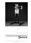
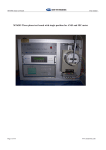
Download Operating Instructions for Oscillating Mill MM400
Transcript
Operating Instructions for Oscillating Mill MM400
© Retsch GmbH, 42781 Haan, Rheinische Str.36, Germany
Doc.Nr. D 98.745.9999
Notes on these operating
instructions
These operating instructions for the oscillating mill, type MM400,
give all the necessary information on the areas mentioned in the
contents.
They instruct the target group(s) for each of the defined areas, in
order to ensure safe handling of the MM 400 when used for the
intended purpose. Knowledge of the relevant section is an
essential precondition for safe, proper use of the machine.
This technical documentation is a reference work and also a set
of teaching instructions. The individual sections are complete in
themselves.
These operating instructions do not include instructions for
repairs. In case of possible defects or necessary repairs please
contact your suppliers or Retsch GmbH direct:
Retsch GmbH, www.retsch.de/
17.07.2007
2
©
Retsch GmbH Doc.Nr.D98.745.9999
Contents
Notes on these operating instructions .................................... 2
Contents.................................................................................. 3
Safety ..................................................................................... 4
Safety instructions ...........................................................................4
Warning signs .................................................................................5
Repairs...........................................................................................5
Confirmation ...................................................................................8
Technical data ......................................................................... 9
Use according to the intended purpose................................................9
Protective equipment...................................................................... 10
Emissions ..................................................................................... 10
Protective systems ......................................................................... 11
Rated power: ................................................................................ 11
Machine dimensions ....................................................................... 11
Required floor space....................................................................... 11
Transport and installation ..................................................... 11
Packing ........................................................................................ 11
Transport...................................................................................... 11
Intermediate storage...................................................................... 11
Supply schedule ............................................................................ 12
Conditions for the place of installation............................................... 12
Installation ................................................................................... 12
Electrical connection....................................................................... 13
Operation .............................................................................. 14
Operating elements and operation .................................................... 14
Graphical representation ................................................................. 14
General table ................................................................................ 15
Display and operating unit............................................................... 16
Inserting / replacing the milling cups ................................................ 17
Setting the milling time .................................................................. 17
Setting the frequency ..................................................................... 18
Starting the milling process ............................................................. 18
Stopping the milling process ............................................................ 18
Storing the milling parameters......................................................... 19
Operating hours display .................................................................. 19
Operating software display .............................................................. 20
Replacing the machine fuses............................................................ 20
Working instructions............................................................. 20
General ........................................................................................ 20
The milling process ........................................................................ 21
Quantities of milling material and grain sizes ..................................... 21
Safety instructions for handling liquid nitrogen ................................... 22
Safety functions and fault displays ....................................... 23
Safety functions............................................................................. 23
General ................................................................................. 24
Cleaning ....................................................................................... 24
Maintenance.................................................................................. 24
Wear............................................................................................ 24
Wearing parts................................................................................ 24
Checks ......................................................................................... 24
Copyright ..................................................................................... 24
Alterations .................................................................................... 25
Accessories for MM 400................................................................... 25
Safety regulations for the MM 400 - summary .................................... 26
Warranty Conditions ............................................................. 27
17.07.2007
3
©
Retsch GmbH Doc.Nr.D98.745.9999
Safety
Target
group: All persons concerned
machine in any way
with
the
The MM 400 is a modern, highly efficient product of Retsch
GmbH, corresponding to state of the art. If the machine is
used according to the intended purpose with a knowledge of
this technical documentation it is completely safe and reliable
to operate.
Safety instructions
As the operating authority it is your duty to ensure that all
persons charged with working on the MM 400:
•
have read and understood all the instructions on
safety,
•
before beginning work know all the instructions
and regulations for the target group relevant to
their work,
•
have access to the technical documentation for
this machine at all times, without problems.
•
New personnel should be familiarized with safe,
proper handling of the machine before beginning
work on the MM 400, either by verbal instruction
from a competent person or through this
technical documentation.
•
Improper operation can cause injury to persons
or damage to the equipment. You are responsible
for your own safety and that of your employees.
•
Ensure that no unauthorised persons have access
to the MM 400.
For your own protection have your employees confirm that
they have been instructed in operation of the MM 400. The
draft of a suitable form is given at the end of the section on
safety.
We exclude any claims for damages of any kind for
injury to persons and damage to equipment arising
from non-observance of the following safety
instructions.
17.07.2007
4
©
Retsch GmbH Doc.Nr.D98.745.9999
Warning signs
Warnings are given by the following signs:
Injury to persons
Damage to equipment
Observe instructions for use
Repairs
These operating instructions do not include repair instructions.
For your own safety repairs must be carried out only by Retsch
GmbH or an authorised agent (service technicians).
In this case please contact:
The Retsch agency in your country
Your supplier
Retsch GmbH directly
Your service address:
____________________________________
____________________________________
____________________________________
____________________________________
17.07.2007
5
©
Retsch GmbH Doc.Nr.D98.745.9999
Safety instructions
We exclude any liability for claims for damages in any form whatsoever for injury to persons or damage to
the machine caused through non-observance of the following safety instructions.
Use according to the intended purpose
Do not make any alterations to the machine and use only spare parts and accessories approved by Retsch.
Otherwise the Declaration of Conformity with European directives made by Retsch will lose its validity.
Furthermore this will also lead to the loss of any guarantee claims.
Packing materials
Please keep the packing material for the duration of the guarantee period, since, in case of a complaint
and return of the machine in unsuitable packing material your guarantee claim will be at risk.
Transport
The MM 400 must not be jolted, shaken or thrown during transport. Otherwise the electronic and
mechanical components may be damaged.
Temperature variations
If subjected to high temperature variations (e.g. during transport by aircraft) the MM 400 must be
protected against condensed water. Otherwise the electronic components may be damaged.
Supply schedule
If the delivery is incomplete and/or transport damage is found, you must inform the transporter and
Retsch GmbH immediately (within 24 hrs). Later complaints may possibly be no longer considered.
Conditions for the place of installation
If the temperature drops below or exceeds the ambient temperature the electronic and mechanical
components may be damaged; the performance data are then altered to an unknown extent.
At high atmospheric humidity the electronic and mechanical components may be damaged and the
performance data are altered to an unknown extent.
Electrical connection
If the values on the rating plate are not observed the electrical and mechanical components may be
damaged.
Inserting / replacing the milling cups
Ensure that the milling cups are inserted correctly in the milling cup holder – otherwise they can become
damaged when starting the machine.
Both milling positions must always be used since otherwise this will cause considerable unbalance.
When removing and opening hot milling cups always wear protective gloves.
Danger of burning the hands.
General
Observe the relevant regulations and directives of your country for handling chemicals and hazardous
materials.
Apply these when working with the MM 400.
Materials
Milling of materials with the MM 400 which give a risk of fire or explosion is prohibited.
Please take the necessary measures, depending on the hazardous nature of your sample, to prevent
danger to persons.
Note also that the properties, and therefore the hazardous nature of your sample, can change during the
milling process.
17.07.2007
6
©
Retsch GmbH Doc.Nr.D98.745.9999
Safety instructions for handling liquid nitrogen
Always wear protective goggles and protective gloves when handling liquid nitrogen.
Liquid nitrogen has a temperature of –196°C and can cause frostbite or injury similar to burns if it comes
into contact with the skin or eyes.
Follow the safety regulations of the cooling liquid supplier.
Retsch GmbH accepts no liability whatsoever arising from the use of liquid nitrogen or similar materials.
Cleaning
Do not clean the MM 400 under running water. Danger to life through current surge.
Use only a cloth moistened with water. Cleaning agents and solvents should not be used – not for cleaning
the milling tools either.
Accessories for the MM 400
Do not make any alterations to the machine and use only spare parts and accessories approved by Retsch.
Otherwise the Declaration of Conformity with European directives made by Retsch will lose its validity.
Furthermore this will also lead to the loss of any guarantee claims.
Wearing parts
These operating instructions do not include any repair instructions. For your own safety repairs should be
carried out only by Retsch GmbH or an authorised agent (service technicians).
17.07.2007
7
©
Retsch GmbH Doc.Nr.D98.745.9999
Confirmation
I have taken note of the sections „Notes on these
operating instructions” and “Safety”
_______________________________________
Signature of operating authority
_______________________________________
Signature of service technician
17.07.2007
8
©
Retsch GmbH Doc.Nr.D98.745.9999
Technical data
Target group: Operating authority, operator
Machine type designation: MM 400
Use according to the intended purpose
The MM 400 is a laboratory machine and is suitable for milling
and homogenising soft, fibrous, hard and brittle materials in
the wet and dry state.
The MM 400 is designed for use with screw-type milling cups
with a steel casing and a milling set with clamping centerings
of dia. 36 mm and a min. clamping length of 60 mm. It is used
for fast, super fine milling of 2 samples simultaneously.
Ceramic milling cups without a complete steel casing must not
be used.
The closed milling system guarantees complete recovery of the
samples. Owing to the extremely short milling time and the
high final fineness of the material to be milled the MM 400 is
also ideally suitable for sample preparation for all spectral
analyses.
Final finenesses of down to 1 µm can be achieved, depending
on the milling time and the specific properties of the sample
material. The optimum milling cup filling is as a rule 1/3 of the
milling cup volume.
Exceptions to this are voluminous materials, such as wool,
leaves, grasses and suchlike. In these cases a filling level of
70-80% is necessary.
The sample quantity should not be less than 25% of
the milling cup volume.
The milling ball/s may otherwise damage the
milling cups.
The milling cup materials and milling ball materials
must always be identical.
The milling ball/s may otherwise damage the
milling cups.
Do not make any alterations to the machine and use
only spare parts and accessories approved by Retsch.
Otherwise the Declaration of Conformity with the
European directives by Retsch loses its validity.
Futhermore this will result in the loss of any kind
of guarantee claim.
Do not clamp any ceramic milling cups of the MM 2/200
or any milling cups without a complete steel casing.
Clamping by the metallic components of the
milling cup holder of the MM 400 can cause
damage to the ceramic parts.
17.07.2007
9
©
Retsch GmbH Doc.Nr.D98.745.9999
Do not use ceramic or natural stone milling cups for
milling graphite or graphite mixtures.
The high lubricating properties of graphite cause high
milling ball speeds, the energy of which cannot be
absorbed by the material owing to its low density.
For this reason there is a danger that the ceramic
or natural stone inserts of the milling cups will be
destroyed by the ball/s.
For further information our application laboratory will
be pleased to assist you.
Protective equipment
The milling chamber of the laboratory mill MM 400 is
enclosed by a strong covering hood.
Starting the machine is possible only with the hood
closed.
Emissions
Noise characteristic values :
The noise characteristic values are also influenced by
the properties of the material to be milled.
Example 1:
Intensity of sound LWA
= 71.4 dB(A)
Emission value related to
= 61 dB(A)
workplace LpAeq
Operating conditions:
Container:
2 steel milling cups of 25 ml
Milling organ:
Material charged:
1 steel ball 20 mm
Quartz crushed pebbles approx.
4.0 – 6.0 mm
Charged quantity:
8ml
Example 2:
Intensity of sound LWA
= 76 dB(A)
Emission value related to
= 65 dB(A)
workplace LpAeq
Operating conditions:
Container:
Milling organ:
Material charged:
Charged quantity:
17.07.2007
10
2 steel milling cups of 5 ml
2 tungsten carbide balls 8 mm
Quartz crushed pebbles approx.
1.0 – 1.5 mm
1.5ml
©
Retsch GmbH Doc.Nr.D98.745.9999
Protective systems
IP30
Rated power:
150 Watt
Machine dimensions
Height:
Width:
Depth:
266 mm up to approx. 524 mm with hood opened
371 mm
461 mm
Weight:
approx. 26 kg
without milling cups
Required floor space
400 mm x 500 mm; no safety distance required.
Transport and installation
Target group: operating authority, transporter,
operators
Packing
Packing is adapted to the transport route and
conforms to generally applicable packaging guidelines.
Please keep the packing material for the duration of the
guarantee period since if there is a complaint and the
machine is returned with inadequate packing your
guarantee claim will be at risk.
Transport
The MM 400 must not be knocked, shaken or thrown
during transport. Otherwise the electronic and
mechanical components can become damaged.
Temperature variations
If temperature variations are high (e.g. during air
transport) the MM 400 must be protected against
condensed water. Otherwise the electronic components
can become damaged.
Intermediate storage
Ensure that the MM 400 is also stored dry during
intermediate storage.
17.07.2007
11
©
Retsch GmbH Doc.Nr.D98.745.9999
Supply schedule
• MM 400
•
1 power supply cable
•
1 set of operating instructions
Check completeness of the delivery, including
individually ordered accessories.
Check perfect functionability of the MM 400 (see also
section on operation).
If the delivery is incomplete and / or there is transport
damage you must inform the transporter and Retsch
GmbH immediately (within 24 hrs). Later complaints
may possibly be no longer considered.
Conditions for the place of installation
Ambient temperature:
5°C to 40°C
If the ambient temperature drops below or exceeds
these values the electronic and mechanical components
can become damaged and performance data are
changed to an unknown extent.
Atmospheric humidity:
Maximum relative humidity 80% at temperatures up
to 31°C,
decreasing linearly down to 50% relative humidity at
40°C.
At higher atmospheric humidity the electronic and
mechanical components can become damaged and
performance data are changed to an unknown extent.
Installation height:
max. 2000 m above sea level
Installation
Mount the MM 400 on a firm, stable laboratory bench
since otherwise vibrations can be transmitted.
17.07.2007
12
©
Retsch GmbH Doc.Nr.D98.745.9999
Remove transport safeguard:
A transport safeguard, which is marked with an arrow,
is located on the underside of the MM 400.
• Unscrew the screw and remove.
• Keep the transport safeguard device for transport at
a later date.
Operation with the transport safeguard or transport
without the transport safeguard can cause damage to
the mechanical components.
Electrical connection
•
The voltage and frequency for the MM 400 are
given on the type plate.
•
Ensure that these values correspond to the
available power supply system.
•
Connect the MM 400 to the power supply system
using the supplied connection cable.
•
Protection by external fusing is to be used when
connecting the mains cable to the power supply,
according to the regulations at the place of
installation.
If the values on the type plate are not observed this
can result in damage to the electrical and mechanical
components.
17.07.2007
13
©
Retsch GmbH Doc.Nr.D98.745.9999
Operation
Target group: operators
Operating elements and operation
Graphical representation
A
Plan view
B
C
D
Front view
17.07.2007
14
©
Retsch GmbH Doc.Nr.D98.745.9999
E
I
F
J
G
H
K
Rear view
General table
Element
Description
Function
A
Display and operating unit: for
explanation see below
Time preselection, frequency preselection,
programme and starting / stopping the
machine
B
Hood
Closes the milling chamber
C
Milling cup holder - left
Holds the milling cup
D
Milling cup holder - right
Holds the milling cup
E
Switch ON / OFF
For switching the MM 400 on and off
F
Fuse compartment
Takes two visible type fuses
G
Machine socket
Connection for power cable of machine
H
Interface RS232
Enables operating software to be updated
I
Sign – Caution! unplug mains
plug
Safety instruction
J
Type plate
Information on the machine and connected
loads
K
Sign – Follow operating
instructions
Safety instruction
17.07.2007
15
©
Retsch GmbH Doc.Nr.D98.745.9999
Display and operating unit
L
M
N
P
O
Element
Description
L
Memory , operating mode and
stand-by
The various operating modes, such as on,
programme and stand-by are displayed here.
PROG
Calls the stored programmes
SET
Stores the set milling parameters
Frequency display
The frequency can be set continuously from 3 to
30 Hz here.
Frequency – minus button
In the on mode and in the operating mode:
Reduction of the set frequency by 0.1
oscillaltions. Continuous pressing switches
on the digits fast running.
Frequency – plus button
In the setting mode and operating mode:
Increase of the set freuqency by 0.1
oscillations. Continuous pressing switches
on the digits fast running.
Time display
Shows the set milling time or, during operation,
the milling time still remaining.
Setting range: 10 seconds to 99 minutes.
Time – minus button
In the on mode and operating mode:
Reduction of the set milling time by one
second. Continuous pressing switches on
the digits fast running.
Time – plus button
In the on mode and operating mode:
Increase of the set milling time by one
second. Continuous pressing switches on
the digits fast running.
Start – button
Starts the milling operation
Green LED
Indicates milling operation
Stop – button
Interrupts or ends the milling operation,
Red LED and ON
Puts the machine into stand-by mode
M
N
P
O
17.07.2007
Function
16
©
Retsch GmbH Doc.Nr.D98.745.9999
Inserting / replacing the milling cups
Place the milling cups, filled with the material to be milled and
the milling balls, into the centering points Z of the clamping
device and clamp firmly. Fig.1/2
SB
•
Remove the locking pin SB upwards from the groove and
turn through 90°. Fig.1/2
This unlocks the locking device.
Abb.1
Z
SB
Z
Abb.2
HD
•
Turn the handwheel HD counterclockwise until the max.
clamping range is reached. Fig.1/2
•
Turn the locking pin SB back through 90° until it engages in
the groove again.
•
Insert milling cup and press lightly into the centering point Z
•
Turn the handwheel HD clockwise with two fingers until the
milling cup just fits, free of play, in the holder. Then
continue to turn the handwheel clockwise through 8 – 12
easily audible “clicks”, while at the same time the locking
pin SB is raised and lowered with clearly audible “clicks”.
The engaged locking pin reliably prevents automatic opening of
the milling cup holder.
If the locking pin SB cannot be pulled upwards to release it,
unlocking should not be forced with a hammer or similar tool.
Otherwise the hardened locking pin can break off.
Briefly retension the handwheel HD in the clockwise direction –
the locking pin can then move freely again.
To remove the milling cup lift the locking pin and turn the
handwheel in the opposite direction to tighten.
In order to guarantee quiet running of the MM 400 both milling
positions must be loaded with approximately the same mass.
Ensure that the milling cups are inserted correctly in the
guides.
Otherwise the milling cup will be damaged when the machine is
started.
When removing and opening hot milling cups always wear
protective gloves.
Danger of burning the hands.
Setting the milling time
• Switch on the MM 400 with switch D
Preselect time:
• Set required milling time with + / - buttons N+ and N• Short pressing of N+ or N- adjusts the time by one second or
one minute. When pressed for longer the display runs
continuously without a pause.
N-
17.07.2007
N+
If 99.0 minutes is exceeded the display L shows 0.10
seconds again.
17
©
Retsch GmbH Doc.Nr.D98.745.9999
Setting the frequency
• Set the frequency with + / - buttons M+ and M-.
• Short pressing of + or – adjusts the frequency in single steps.
With longer pressing the display runs faster. Selectable
frequency range is from 3 to 30 Hz.
M-
M+
Starting the milling process
• Shut the hood.
• Set the frequency.
• Set the time.
• The milling operation is started with start button P.
N
P
O
• The milling time is recorded and the milling time still
remaining is shown in display N.
The milling process can be started only when the hood is
closed.
Stopping the milling process
• Press the stop button O.
• Pressing once interrupts the milling process, for example in
order to assess the milled material. The milling time still
remaining is still visible in the display N. By repressing the
start button the mill continues to run until the milling time
has completely elapsed.
• Pressing the stop button twice stops the milling process. The
machine is now in the stand-by mode.
• Pressing the start button reactivates the display and the
milling time is reset to the last starting value.
During the milling process the time can be adjusted by pressing
the N+ or N- button.
When the milling time has elapsed the milling process is
automatically ended. The display is reset to the last started
value.
17.07.2007
18
©
Retsch GmbH Doc.Nr.D98.745.9999
Storing the milling parameters
Storing or calling the preselected milling parameters can be
carried out only in the on mode.
After switching on the MM 400 “on” appears in the display L.
PROG
By pressing the button PROG the next programme position P1
to P9 can be obtained. After programme position P9 „on“
reappears in the display. In the PROG mode all buttons, apart
from PROG, START and STOP are blocked.
SET
L
•
When the display shows on
the frequency M and time N are freely adjustable.
•
When the display shows P1 to P9
milling parameters can be stored and called
•
Start = the milling process is started with the selected
programme or the parameters freely selected under
„on“ .
Allocating the storage location
•
Press button PROG once or several times until the
required storage location P1-P9 has been reached.
•
Press SET button – all displays flash.
•
Set frequency M and time N.
The programming mode can be discontinued by pressing the
button PROG – the values are not stored.
•
Press SET button – the values are stored.
Flashing of the display stops, the adjustment interlock is
activated and the milling parameters are stored.
Operating hours display
If the buttons described below are pressed in the stand-by mode
the complete running time of the machine is shown in hours and
minutes.
Display operating hours :
• Press buttons M+ and SET simultaneously and keep pressed.
“bS” appears in the display “memory”.
Leave operating hours :
• Press STOP button.
hhh
17.07.2007
hhh
19
©
Retsch GmbH Doc.Nr.D98.745.9999
Operating software display
When the buttons described below are pressed in the stand-by
mode the actual software version is displayed.
Display operating software:
• Press buttons M- and SET simultaneously and keep pressed.
„S“ appears in the display „memory“ and the actual software
version appears in the display “frequency 1/s”.
Leave operating software display :
• Press STOP button.
Replacing the machine fuses
B
A
The following visible type fuses are required for the MM 400:
2 MT 3.15 A fuses
Replacing the fuses
• Unplug mains plug from the machine socket A
• By pressing the locking devices on the side of the fuse
compartment B these are released and can be pulled out.
• Replace fuses
• Insert fuse holder B so that it engages.
Working instructions
Target group: operators
General
The MM 400 is an ultramodern, high performance product
from Retsch GmbH.
Owing to the large selection of accessories the oscillation
mill, type MM 400, is a machine with many different
application possibilities in laboratories in industry and
research. It is used mainly in the chemical and
pharmaceutical sectors and in mineralogical and biological
applications etc.
17.07.2007
20
©
Retsch GmbH Doc.Nr.D98.745.9999
The milling process
Clamp the machine filled with material to be milled, together with
the milling ball/s in the milling cup holder as described.
• Close the hood.
• Set the milling parameters.
• Start the MM 400.
Do not open the hood during the milling process.
Although the milling cups are brought to a standstill immediately
by the built-in brake, the millling process can no longer be
continued with the remaining running time.
The MM 400 must be restarted and the initial parameters are then
again available.
In order to guarantee quiet running of the MM 400 we recommend
that milling cups with the same mass as far as possible are
clamped in both milling positions.
Do not open the plexiglass hood during the milling process.
Although the milling cups are brought to a standstill immediately
by the built-in brake, the milling process can no longer be
continued with the remaining running time.
The MM 400 must be restarted and the initial parameters are then
again available.
Milling cup
volume in ml
Quantities of milling material and grain sizes
Milling material
Ball filling
max. charging grain
quantity in ml
optional
size in mm
min – max
Number dia. in mm
25
4 – 10
1
15
6
35
6 – 15
1
20
6
50
8 – 20
1
25
8
Milling of materials which can cause a fire or explosion in
the MM 400 is prohibited.
Please take any necessary measures to prevent danger to
persons, depending on the dangerous nature of your
sample.
Please note that the properties, and therefore the
dangerous nature of your sample, can change during the
milling process.
17.07.2007
21
©
Retsch GmbH Doc.Nr.D98.745.9999
Safety instructions for handling liquid
nitrogen
The MM 400 is also designed for cryogenic milling.
As an accessory for cold milling we also supply a cryo kit for
cooling the milling cups with liquid nitrogen.
Cryo kit order number: 22.354.0001.
When handling liquid nitrogen always wear
protective goggles and protective gloves.
Liquid nitrogen has a temperature of – 196°C and can
cause injury similar to burns or frostbite in contact with the
skin or eyes.
Protective goggles also protect the eyes against serious
injuries through flying glass splinters, which may be caused
through bursting of glass containers as a result of low
temperature tension.
Please follow the safety regulations of the cooling
liquid supplier.
Retsch GmbH excludes any liability claims whatsoever
which may arise through the use of liquid nitrogen or
similar materials.
17.07.2007
22
©
Retsch GmbH Doc.Nr.D98.745.9999
Safety functions and fault displays
Safety functions
F01
F01 - Overloading
In order to avoid overloading of the drive motor and resulting
endangerment to the user the MM 400 is fitted with a load monitoring
device.
In case of overloading the monitoring function switches the machine
off in good time and allows the necessary cooling time. The user
recognises this by an alternating flashing display F01 and an
indication of the remaining cooling time, e.g. 0.3, = 3 minutes.
At the end of the cooling time it is only necessary to switch the
machine off and on again in order to be able to operate it normally
again.
F02
F02 – Speed recognition, zero speed
If the drive does not start up after pressing the start button there is a
fault in the system. Possible causes: drive blocked, motor or speed
sensor defective.
F03 – Speed recognition, overspeed
F03
If the specified frequency is exceeded after starting, „F3” appears in
the display and the machine is switched off.
Possible cause of fault: defective speed sensor.
F04 – Hood open
F04
The drive must not run when the hood is open. This serves to protect
the operator against injury. If the hood is opened when the machine
is running the control unit switches the drive off immediately and
“F04” appears in the display. If the start button is pressed with the
hood open in order to start the milling process “F04” is also displayed
and the drive is not started.
This alarm can be cancelled by pressing the stop button.
F05 –Keyboard monitor
F05
If one or more buttons are pressed for longer than 15 seconds the
control unit switches the drive off and displays “F05”.
This function is intended to prevent unintentional faulty operation if
any object accidentally presses on the keyboard.
In order to cancel this fault alarm switch the machine off and on
again once.
F06 – Magnetic speed monitoring sensor
F06
F07
17.07.2007
If one of the magnets that monitors speed is missing or defective,
this will be detected by the control, which will then switch off the
machine. “F06” will appear in the display. To eliminate this fault, it
must be repaired by authorised Retsch service technicians.
F07 – Magnetic switch – hood monitoring
If the magnetic switch which monitors hood opening has a defect in
the supply line this is recognised by the control unit and causes the
machine to be switched off. “F07” appears in the display. To eliminate
this fault repair by an authorised Retsch service agent is necessary.
23
©
Retsch GmbH Doc.Nr.D98.745.9999
General
Cleaning
Do not clean the MM 400 with running water.
Danger to life through current surge
Use only a cloth moistened with water. Cleaning agents
and solvents must not be used – not for cleaning the
milling tools either.
Maintenance
The MM 400 is maintenance-free. When used properly
no maintenance and setting work need be carried out.
Do not make any alterations to the machine and use only spare
parts and accessories approved by Retsch.
Otherwise the declared conformity with the European
directives by Retsch will lose its validity. Furthermore
this will lead to loss of any kind of guarantee claims.
Wear
The milling tools can become worn, depending on the
frequency of the milling operation and the material to
be milled. The milling cups and ball(s) should be
regularly checked for wear and replaced if necessary.
Wearing parts
These operating instructions do not include instructions for
repair. For your own safety repairs should be carried out only
by Retsch GmbH or an authorised representative (service
technicians).
Checks
Correct functioning of the hood switch must be checked
regularly:
• Switch on the machine with switch E.
• Start milling operation with start button P.
• Lift the hood.
• If there is an opening gap of a few cm the machine is
switched off and F4 appears in the display.
• Cancel F4 with stop button O.
If this switching off function does not take place the MM 400
must be checked immediately by Retsch service.
Copyright
Distribution or duplication of this documentation, using
or passing on the contents, is allowed only with the
express permission of Retsch GmbH.
Anyone violating is liable to pay damages.
17.07.2007
24
©
Retsch GmbH Doc.Nr.D98.745.9999
Alterations
Subject to technical alterations without notice.
Accessories for MM 400
Designation
Material
Article no.
Milling cup 25 ml
Hardened steel
01.462.0237
Milling cup 1.5 ml
Stainless steel
01.462.0230
Milling cup 5 ml
01.462.0231
Milling cup 10 ml
01.462.0236
Milling cup 25 ml
02.462.0213
Milling cup 35 ml
01.462.0214
Milling cup 50 ml
01.462.0216
Milling cup 10 ml
Tungsten carbide
Milling cup 25 ml
Milling cup 5 ml
01.462.0217
Agate
Milling cup 10 ml
Milling cup 10 ml
01.462.0235
01.462.0232
01.462.0233
Zirconium oxide
01.462.0234
Milling cup 25 ml
02.462.0201
Milling cup 35 ml
01.462.0215
Milling cup 25 ml
Teflon
Milling cup 35 ml
01.462.0238
01.462.0244
Milling balls dia.
5,7,9,12,15 mm
Hardened steel
Milling balls dia.
5,7,9,12,20,25 mm
Stainless steel
Milling balls dia.
5,7,9,12,15 mm
Tungsten carbide
Milling balls dia.
5,7,9,12 mm
Agate
Milling balls dia.
12,15,20 mm
Zirconium oxide
Milling balls dia.
10,12,20 mm
Teflon with steel core
Milling balls dia.
5,7,9,12 mm
Polyamide for mixed
vessels
Further accessories are given in our price list or in
internet under www.retsch.de
17.07.2007
25
©
Retsch GmbH Doc.Nr.D98.745.9999
Safety regulations for the MM 400 - summary
Subject
Action
Danger
Safety
Danger to persons and damage to the Claims for damages in any form are
equipment caused through non-observance excluded
of the safety instructions
Transport
Do not knock, shake or throw the MM 400 Electronic and mechanical components
during transport
can be damaged
Keep the packing material for the duration of Complaint and return of the goods in
the guarantee period
inadequate
packing
puts
your
guarantee claim at risk
Temperature
variations
Protect the MM 400 from condensed water if Electronic
there are temperature variations
damaged
Supply schedule
If the delivery is incomplete and / or there is Later complaints may
transport damage you must inform the longer be considered.
transporter and Retsch GmbH immediately
(within 24 hrs).
Ambient
temperature
Temperature drops below 5°C
Atmospheric
humidity
Electrical
connection
components
can
possibly
no
Electronic and mechanical components
can be damaged.
Temperature exceeds 40°C
Performance data are changed to an
unknown extent.
Exceeds 80% at
Electronic and mechanical components
can be damaged.
temperatures up to 31°C
Performance data are changed to an
unknown extent.
Mains power supply does not agree with Mechanical and electronic components
values on type plate
can be damaged.
Fault-current circuit breaker must
incorporated into the power supply.
be
Prevents electric shock if machine has
an electrical defect.
Inserting milling Ensure that the milling cups are positioned Milling cups
correctly in the guides.
damaged.
cups
and
holder
can
Checks
Check hood switch regularly
Danger of injury if defective
machine open during operation.
Cleaning
Do not clean with running water
Danger
surge
17.07.2007
be
26
©
to
life
through
be
and
current
Retsch GmbH Doc.Nr.D98.745.9999
Warranty Conditions
1.
If legitimate claims are made we shall remedy the defect or replace the goods free of charge.
The purchaser shall only have a right to rescind the contract or reduce the purchase price if
we have decided that it is not possible to remedy the defect and a replacement delivery
cannot be made or the time limit therefore cannot be complied with or if a reasonable
additional time limit of six weeks granted by the customer has not been complied with due to
our fault.
If the remedy or replacement delivery in fact fails the customer shall have the right to reduce
the price or rescind the contract at his discretion. Further claims, in particular for damages in
relation to damage not caused to the goods themselves, such as lost production, are excluded
in so far as we have not acted wilfully or negligently. For goods produced by third parties we
pass on the liability of the manufacturer.
2.
We shall bear the costs directly incurred through the remedying of defects or the replacement
delivery on the condition that claim is found to be legitimite. This also applies to the freight
costs as well as the reasonable costs of removal and installation. The customer, however,
undertakes to bear the reasonable costs of providing his own technicians and assistants on
site.
If our customer carries on business overseas, however, we shall be entitled to pay the costs,
in particular costs of transport, tolls, wages and materials, ex German border.
3.
The warranty term for newly manufactured goods is two years, for used it is one year.
The guarantee refers to deployment in a laboratory in 1-shift operation. In case of multi-shift
operation or other areas of application, the guarantee term is shortened accordingly.
No warranty is given for parts subject to wear and tear.
4.
We warrant that our goods are free from manufacturing defects. The suitability, classification
and function of our goods are determined exclusively on the basis of the performance
descriptions contained in the order confirmation even if these differ from the order. In the
latter event the customer may, within two weeks after receipt of the order confirmation, draw
any possible difference from the order to our attention and come to an agreement on these
with us. If the customer does not object to the specifications in the order confirmation then
these shall be deemed to have been accepted.
Unless an agreement to the contrary has been reached, we shall not be held liable for the
suitability of the goods delivered for the use to which the customer intends to put them. The
same applies to performance figures expected by the customer unless we have been able to
carry out appropriate preliminary practical experiments and have, in our order confirmation,
declared in writing that these performance figures shall be binding.
5.
Our warranty shall also become invalid if persons other than those employed by us carry out
repairs or in any other way interfere with or make alterations to the goods delivered by us or
do not use suitable parts to the extent that the defect is causally connected thereto. In
addition, it is a condition of our warranty that our directions for use and operation be
followed.
6.
If, without a release having first been obtained from us, the goods are installed in and /or
connected to, attached to or incorporated in other systems or production plants then our
guarantee is limited exclusively to the parts delivered by us.
7.
The remedying of defects or replacement of defective parts shall, at our discretion, be carried
out on site or at the seat of our company. If the repair is carried out on site, the customer
shall ensure that our employee has access, unlimited in either time or space, to the purchased
item. In addition, the customer may only demand that work necessary in order to fulfil
warranty obligations be carried out during the normal local business hours. If such work is
carried out outside our normal business hours on request, the customer shall bear the
additional costs. If he wishes to have other particular work performed which goes beyond the
work warranted then these costs shall be payable at the actual valid price.
17.07.2007
27
©
Retsch GmbH Doc.Nr.D98.745.9999


