1
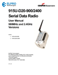
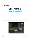
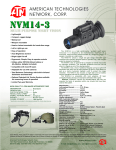
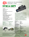
– – User Manual 334-0001-00-10-LE, rev. 100 May ’08 334-0001-00-10-LE, rev. 100 May ’08 i AMERICAN TECHNOLOGIES NETWORK CORP. 1341 San Mateo Avenue, South San Francisco, CA 94080, USA 800-910-2862, 650-989-5100, FAX 650-875-0129 European Office: 44-(0)870-0111286, FAX 44 (0)845 3349142 The Following Countries can use our Toll Free Number: 00800 9102-8620 Austria, France, Germany, Holland, Italy, Spain, Sweden, Switzerland www.atncorp.com E-mail: [email protected], [email protected] Warnings and Cautions 1 Introduction 2 Getting Started 3 Caring for your PathFindIR LE 4 Options and Accessories 5 Technical Data 6 Installation 7 Infrared Technology 8 334-0001-00-10-LE, rev. 100 May ’08 iii – iv May ’08 334-0001-00-10-LE, rev. 100 1 Warnings and Cautions 1.1 Cautions ................................................................................. 1 1.2 General Information ................................................................. 2 2 Introduction 2.1 2.2 2.3 2.4 2.5 Overview ................................................................................. 3 Thermal Imaging Driver Vision Enhancement System .................. 3 What is Thermal Imaging? ........................................................ 5 Vehicles that use PathFindIR LE ............................................... 5 Part Numbers .......................................................................... 6 3 Getting Started 3.1 3.2 3.3 3.4 3.5 3.6 Using your PathFindIR LE ........................................................ 7 Initial System Startup .............................................................. 7 Heater Element ....................................................................... 8 Automatic Shutter ................................................................... 8 In Case of Difficulty ................................................................. 8 Troubleshooting ....................................................................... 9 4 Caring for your PathFindIR LE 4.1 Product Cleaning ................................................................... 11 4.2 Temperature ......................................................................... 11 4.3 Maintenance ......................................................................... 11 5 Options and Accessories 5.1 Accessories ........................................................................... 13 5.1.1 PathFindIR Interface Cable ........................................... 13 5.1.2 PathFindIR LE Vision Enhancement Kit .......................... 14 6 Technical Data 6.1 Performance Specification ...................................................... 15 6.1.1 Side View .................................................................... 16 6.1.2 Side View, Additional Dimensions .................................. 17 6.1.3 Front View ................................................................... 18 7 Installation 7.1 7.2 7.3 7.4 7.5 PathFindIR LE Installation ..................................................... 19 Preparation ........................................................................... 19 Installation ........................................................................... 20 Installation Guidelines and Precautions ................................... 20 Installation Assistance ........................................................... 21 334-0001-00-10-LE, rev. 100 May ’08 v 7.6 Mounting Assistance .............................................................. 21 8 Infrared Technology 8.1 History of Infrared ................................................................ 23 8.2 How do Infrared Cameras Work? .............................................. 27 vi May ’08 334-0001-00-10-LE, rev. 100 1 Warnings and Cautions 1.1 Cautions 1 Caution! This guide uses the term Caution to indicate a potentially hazardous situation, which, if not avoided, may result in injury, damage to the vehicle or PathFindIR LE, or other property damage. Do not operate any function that takes your attention away from safely driving your vehicle. Any function that requires your prolonged attention should only be performed after coming to a complete stop. Always stop the vehicle in a safe location before performing these functions. Failure to do so may result in an accident. Consult your local and state driving regulations prior to installation. In many states using active monitors in view of the driver is prohibited. Consult your local and state driving regulations for laws and guidelines. User assumes all risks and indemnifies the manufacturer from any liability. Minimize display viewing while driving. Viewing the display may distract the driver from looking ahead and may result in an accident. The PathFindIR LE thermal imaging system should not be used as a substitution for head lamps or head lamp assisted human vision during vehicle operation. Use this product for mobile 12VDC applications. Use for other applications may result in excess heat, fire, and equipment malfunction. When installing the PathFindIR LE, do not block the vehicle’s vents or radiator panels. Doing so may result in heat buildup, equipment breakage, and/or fire. 334-0001-00-10-LE, rev. 100 May ’08 1 1 – Warnings and Cautions 1.2 General Information Caution! The PathFindIR LE thermal imaging system is not intended to be used as the primary navigation system. The PathFindIR LE should not to be used as a substitution for head lamps or head lamp assisted human vision during vehicle operation. It should be used only as an aid to cautious night-time driving. Do not open the camera body for any reason. Disassembly of the camera (including removal of the cover) can cause permanent damage and will void the warranty. Operating the camera outside of the specified input voltage range or the specified operating temperature range can cause permanent damage. Do not image extremely high intensity radiation sources, such as the sun, lasers, arc welders, etc. The camera is a precision optical instrument and should not be exposed to excessive shock and/or vibration. Refer to paragraph 6.1 “Performance Specification” on page 15 for detailed environmental requirements. Great care should be used with your camera optics. They are delicate and can be damaged by improper cleaning. Refer to Chapter 4 “Caring for your PathFindIR LE” on page 11. All thermal imaging systems are subject to export control. Please contact FLIR for export compliance information concerning your application or geographic area. 2 May ’08 334-0001-00-10-LE, rev. 100 2 Introduction PathFindIR LE - See More, Be Safer! 2 2.1 Overview Congratulations! You have purchased one of the most sophisticated and important instruments you will have on your vehicle. The FLIR ThermoVision®PathFindIR LE is a state-of-the-art thermal imaging system that will provide you with excellent night visibility and situational awareness, even in absolute darkness. The PathFindIR LE system is designed for simple, intuitive operation. The PathFindIR LE camera is a sophisticated thermal sensor that converts thermal content (heat) of a scene into a 2-dimensional image for display on a video monitor inside your vehicle. 2.2 Thermal Imaging Driver Vision Enhancement System The FLIR Systems, Inc. PathFindIR LE camera is a high performance, rugged, thermal imaging camera designed to provide driver vision enhancement in adverse weather conditions and better situational awareness than with traditional head lamps. Many serious accidents occur at night because the driver is not able to see the cause of the accident in time to prevent the collision. PathFindIR LE directly addresses this problem, allowing drivers to see farther ahead on nighttime roadways and identify potential problems earlier. The majority of trucking accidents occur in rural areas, where visibility is severely reduced at night. Humans and other warm blooded animals offer significant thermal contrast to driving backgrounds and are easy to spot with the PathFindIR LE. The system allows drivers to see without any additional lighting and provides real-time imaging at any speed. Different than visible light cameras, thermal imagers do not display reflected light as seen with human eyes. Rather, thermal imaging cameras only 'see' temperature differences which are converted into shades of grey, from black to white. The PathFindIR LE camera displays cold objects as black and hot objects as white. 334-0001-00-10-LE, rev. 100 May ’08 3 2 – Introduction When using a thermal imager in darkness, the image is created based on temperature differences of objects in the field of view, rather than reflected light from headlights. Furthermore, because thermal imaging cameras only 'see' heat sources and not reflected light, they are ideal to assist with driver vision and situational awareness for oncoming obstructions such as animals, people, and other vehicles . Figure 2-1: PathFindIR Makes the Difference The above images show a comparison of typical night time driving compared to using the PathFindIR LE thermal imager. The image on the left is from an ordinary digital camera and shows the amount of visible light as illuminated by headlights; the image on the right is a thermal image created by the PathFindIR LE thermal imaging camera. Note the PathFindIR LE camera is sensitive to warm objects, such as the deer, and provides visibility over a much greater distance. Some of the objects that are most critical for a driver to avoid are people and animals. Because these objects are naturally warm, they are particularly easy to see with the PathFindIR LE and clearly stand out in the video image. 4 May ’08 334-0001-00-10-LE, rev. 100 2 – Introduction 2 – Introduction Although adverse conditions such as heavy fog will affect any driver vision enhancement system, thermal imaging cameras such as the PathFindIR LE have been shown to continue to provide useful information in conditions of reduced visibility, such as haze and smoke. While the PathFindIR LE can assist drivers with detection of obstructions in the vehicle’s path, thermal imagers should not be used as the sole vision method of the driver. PathFindIR LE is specifically designed to withstand a harsh environment, with a hermetically-sealed external housing resistant to rocks, sand, salt, and under-hood contaminants. Additionally, the wide operating temperature range allows the PathFindIR LE to maintain high performance in severe weather conditions. 2.3 What is Thermal Imaging? With our eyes, we see visible light. With a thermal imager, we can see infrared - a form of light just beyond the visible spectrum. Thermal imagers show subtle differences in temperature; warm objects appear white and cooler objects appear black. In addition to driver vision enhancement, FLIR's thermal imaging cameras are used in a wide variety of applications, including fire fighting, security, maritime, industrial and medical applications. They continue to be used by militaries worldwide to navigate at night and in battlefield conditions. Over the last few years, volume production of these systems has allowed FLIR to offer the same high performance cameras designed for military use to the commercial market. 2.4 Vehicles that use PathFindIR LE PathFindIR LE can increase the detection time for hazards and reduce the probability of an accident - providing confidence and saving lives and property. PathFindIR LE provides improved situational awareness often necessary when performing investigations and when responding to emergencies. Emergency vehicles - Emergency vehicles' high speeds and degraded stopping distances increase the chance of an accident - PathFindIR LE improves hazard detection at high speeds. 334-0001-00-10-LE, rev. 100 May ’08 5 2 2 – Introduction Open rural roads - PathFindIR LE can reveal people, animals and obstructions at long ranges in complete darkness. This early detection capability can significantly increase reaction time. Hard-to-see conditions - PathFindIR LE improves awareness in conditions that render eyesight and daylight cameras useless. The PathFindIR LE can see clearly through dust and smoke, increasing safety for everyone on the job site. 2.5 Part Numbers The PathFindIR LE kit (part number 421-0034-00) contains the standard PathFindIR camera (part number 334-0001-00, 30Hz, NTSC format) as well as a monitor, bracket, and cables required for a complete installation. Refer to Chapter 5 “Options and Accessories” on page 5-13 for more details. All thermal imaging systems are subject to export control. Standard NTSC (30Hz) and PAL (25Hz) units are subject to export restrictions and licensing by the United States Government. Models with video frame rates at or below 9Hz do not require licensing but do require compliance with other export requirements. Please contact FLIR for details concerning export compliance for your application or geographic area. 6 May ’08 334-0001-00-10-LE, rev. 100 3 Getting Started The thermal imaging camera inside the PathFindIR LE is completely sealed and extremely rugged. The camera has been qualified for operation in all types of weather conditions over the specified operating temperature range and includes an automatic window heater that will prevent icing under most conditions. 3.1 Using your PathFindIR LE The PathFindIR LE is easy to use, but you should take a moment to carefully read this section so you fully understand what you are seeing on your display. While the imagery you will see on the monitor may look like black and white daylight video, it isn’t! A few tips on how to interpret some of the imagery will help you to make the most of your system. The camera automatically adjusts to changing scene conditions so no additional camera control is necessary. Scenes with familiar objects will be easy to interpret with some experience. The camera automatically optimizes the image to provide you with the best contrast in most conditions. The thermal imager inside the camera does not sense light like conventional cameras; it senses heat or temperature differences. As you experiment with the system during nighttime operation, you will notice variances in the “picture quality”; this is normal. The camera senses small “differences” in apparent radiation from the objects in view, and displays them as either white (or lighter shades of gray) for warmer objects, and black (or darker shades of gray) for colder objects. 3.2 Initial System Startup The PathFindIR LE camera requires power and a connection to an external monitor to provide imagery. Make sure to test the system prior to installation to assure the system is functioning properly. Be sure to remove the protective window sticker prior to test and installation. Upon initial power up you will hear a slight clicking sound. This click is the internal image correction. This noise is the mechanical shutter assembly which will cause the image to momentarily “freeze.” This noise and image freezing will occur until the unit has reached a thermally stable 334-0001-00-10-LE, rev. 100 May ’08 7 3 3 – Getting Started temperature and periodically thereafter. See “Automatic Shutter” on page 8. 3.3 Heater Element The PathFindIR LE has a built-in heating element to stabilize the window and prevent ice build-up in cold weather conditions. The heating element is automatically turned on when the temperature of the window falls below 4ºC and is tuned off when the temperature reaches 6ºC. 3.4 Automatic Shutter The PathFindIR LE incorporates an automatic image correction feature via the internal calibration shutter. This shutter will activate every 2 minutes or more frequently during initial start up and large environmental temperature changes. During this function the image will be “frozen” for approximately half a second. The frozen image will display a small white box in the left middle portion of the image during this calibration, as shown in the image below. 3.5 In Case of Difficulty The PathFindIR LE comes with a 12 month limited warranty from the date of purchase. DO NOT OPEN, MODIFY, or ALTER the PathFindIR LE unit or accessories. Doing so will void any warranty and may cause system malfunction, loss of performance, fire, or bodily harm. 8 May ’08 334-0001-00-10-LE, rev. 100 3 – Getting Started 3 – Getting Started The PathFindIR LE is a highly sophisticated electronic imaging system. Should the system fail for any reason do not attempt to fix the system or wiring cables yourself. Check wiring connections, power input, video output. If system is not performing please contact the manufacture at +1.888.747.3547 or +1.805.964.9797 and ask to speak to the service department. You will need the serial number of the unit to obtain a Return Material Authorization. 3.6 Troubleshooting No Video but the system is running and has power supplied to it. Place your ear next to the PathFindIR LE unit. If you hear the mechanical shutter (clicking noise, see section 3.2 “Initial System Startup” on page 7) but you are not getting an image, check the video connections. The PathFindIR LE works with most standard NTSC or PAL monitors that have 75 ohm input. No Video, no clicking. If video is not displayed and you do not hear a "clicking" sound from the PathFindIR LE, check the power inputs. The PathFindIR LE runs on 6V to 16V power through the optional 20 foot standard cable power leads. If this voltage is exceeded the unit will not function and may be damaged. The image is cloudy or hazy, or the window has fog or ice built up. The PathFindIR LE is equipped with an automatic heating element which turns on at cold temperatures. The heater requires a few moments to stabilize the window. Once the window is thermally stabilized the heating element will turn off automatically. The image has "lines" or screen door appearance. Check to see if the image "freezes" or if you hear a mechanical "clicking noise" from the PathFindIR LE unit. If you do not see the image freeze momentarily (this may take a few minutes), the internal shutter may be damaged. Contact the manufacturer. 334-0001-00-10-LE, rev. 100 May ’08 9 3 3 – Getting Started The image is shaky. Check your mounting. The PathFindIR LE does not incorporate image stabilization and must be mounted soundly and securely. Image is dim. Check your monitor and video connections. It is recommended that you use separate power supplies for the PathFindIR LE and the local display to make sure you have clean uninterrupted power. Also, verify the PathFindIR LE is connected to the 75 ohm input on the monitor. The image may be dim if the camera is connected to an input that requires a different impedance. The image is dark and no objects are seen. Recycle the power and see if you get the "Splash Screen" (as seen below) on the display. If you get the Splash Screen but no image afterwards (only a black screen), check to make sure that the window is clear of all obstructions (refer to the maintenance section for information on window cleaning). If you do not see the Splash Screen, check the power input and video output. If you see the Splash Screen but no image afterwards, it is possible the mechanical shutter is stuck in the on position. Contact FLIR customer service for additional help. Figure 3-1: Startup Splash Screen 10 May ’08 334-0001-00-10-LE, rev. 100 4 Caring for your PathFindIR LE 4.1 Product Cleaning Caution! Do not open the camera body for any reason. Disassembly of the camera (including removal of the cover) can cause permanent damage and will void the warranty. Your PathFindIR LE camera images through an infrared transparent window. This window is designed for the harsh automotive environment of normal driving, but may require occasional cleaning. FLIR Systems Inc. suggests that you clean the window of the PathFindIR LE when image quality degradation is noticed or excessive contaminant build-up is seen on the window. The camera housing has a durable coating and the rugged protective window is designed to withstand normal cleaning. Rinse the camera housing with low pressure fresh water to keep it clean. If the front window of the PathFindIR LE gets water spots, wipe it with a clean soft cotton cloth dampened with fresh water. If the window requires further cleaning, use a soft moist cotton-based cloth with isopropyl alcohol or dish soap. Do not use abrasive materials, such as paper or scrub brushes as this will possibly damage the window by scratching it. Only clean the window when you can visually see contamination on the surface. 4.2 Temperature The PathFindIR LE camera has an operating temperature range of -40 to 80oC. Choose an installation location so that the PathFindIR LE is not subject to temperature extremes that exceed this range. 4.3 Maintenance If you have problems do not attempt to repair the PathFindIR LE unit yourself. The PathFindIR LE camera is a water-tight sealed unit and can 334-0001-00-10-LE, rev. 100 May ’08 11 4 4 – Caring for your PathFindIR LE not be opened or serviced in the field. Consult your installation dealer or FLIR Systems Inc. for repair information. If the camera will not produce an image, check the video connection at the camera and at your display. If the connectors appear to be properly engaged but the camera still does not produce an image, have an authorized service representative make the appropriate repairs. Front Window Figure 4-1: Front Window Caution! Improper care of the camera window can cause damage to the anti-reflective coating, degrade the camera’s performance, and void the camera warranty. 12 May ’08 334-0001-00-10-LE, rev. 100 5 Options and Accessories 5.1 Accessories Camera options and accessories are subject to change. Refer to the FLIR web site http://www.flir.com or contact your local dealer to obtain up-todate information regarding available accessories such as mounting kits, monitor options, cables and accessories. 5.1.1 PathFindIR Interface Cable Part Number: 308-0121-00 The standard 20 foot system cable ensures a sealed connection to the PathFindIR LE, a requirement for harsh vehicle environments. Cable includes sealed PathFindIR connector at one end and two open power leads and a BNC video connection at the other end. Power Leads Video output Connect to PathFindIR 334-0001-00-10-LE, rev. 100 May ’08 13 5 5 – Options and Accessories 5.1.2 PathFindIR LE Vision Enhancement Kit The FLIR PathFindIR LE Vision Enhancement Kit, part number 4210034-00, is made available to facilitate installation in most Law Enforcement vehicle applications. The kit contains: PathFindIR LE camera Universal Mounting Bracket and hardware PathFindIR Interface Cable 308-0121-00 Safety Vision 7” Monitor with Mounting Bracket and Sun Shield Monitor Interface Cable SV-513 The following diagram shows how to connect the PathFindIR LE using the cables in the kit. 14 May ’08 334-0001-00-10-LE, rev. 100 6 Technical Data 6.1 Performance Specification 6 Thermal Imaging Performance Sensor type Uncooled microbolometer Field of view 36° h x 27° v Spectral band 8 - 14 μ Resolution 320 x 240 pixels Time to Image < 2 sec. Focal Length 19 millimeters Outputs Video NTSC or PAL Connector types 12-pin automotive connector for power in, video out 30-Hz for NTSC Video, 25 Hz for PAL video Frame Rate Note: Hz is equivalent to frames per second < 9 Hz Export Compliant Power Power requirements 12 VDC nominal (range 6V to 16V) Power consumption 2 Watts (nominal) 8 Watts with heater turned on Environmental Operating temperature -40º C to +80ºC Impact protection High-impact resistant window with heating element Weather Resistance Hermetically sealed, pressurized enclosure For additional information, contact FLIR. Dimensions and Weight Dimensions (Width x Height x Length) 58mm x 57mm x 72mm (2.3” x 2.2” x 2.8”) excluding connector Connector adds 25.7 mm to height Weight less than 0.4 kg (0.88 lb.) Mounting Points 2 per side, M4x0.7 6mm screws required 334-0001-00-10-LE, rev. 100 May ’08 15 6 – Technical Data 6.1.1 Side View 16 May ’08 334-0001-00-10-LE, rev. 100 6 – Technical Data 6 – Technical Data 6.1.2 Side View, Additional Dimensions 6 334-0001-00-10-LE, rev. 100 May ’08 17 6 – Technical Data 6.1.3 Front View 18 May ’08 334-0001-00-10-LE, rev. 100 7 Installation 7.1 PathFindIR LE Installation The PathFindIR LE is a compact, sealed imaging system that fits easily behind vehicle grilles and in other compact locations. It includes an internal heater to keep the lens clear in icy conditions, and delivers superior image quality. It can be ordered as a camera module with a commercial grade cable. The PathFindIR LE must be mounted in a location where it is not obstructed by the windshield or other glass materials. Although glass is transparent to the human eye, it is opaque in the infrared spectrum. The PathFindIR LE should be installed by an installer or dealer trained by FLIR Systems, Inc. If one is not available in your area we recommend that you use a reputable car audio/video installation shop that specializes in mobile video system integration. The wiring and installation requires special care and integration techniques. Improper installation may result in damage to the camera and may void the warranty. Some modifications to the vehicle’s exterior may be required, as well as integration into various display units, including factory LCD or aftermarket multi-functional display units. 7.2 Preparation The PathFindIR LE Standard 20 foot system cable has two open power leads to be connected to a power source operating between 6V - 16V. The standard cable accessory also includes a BNC male end. Refer to the model number for your specific analog video output format. It is recommended that power to the monitor be supplied separately from power to the PathFindIR LE unit to assure clean (low noise) power to both items. Otherwise the video image may appear to have interference, ghosting, or undesirable video artifacts. Caution: Before wiring the camera, disconnect all power from the battery. Failure to do so may result in shock, bodily harm, or damage to system. 334-0001-00-10-LE, rev. 100 May ’08 19 7 7 – Installation 7.3 Installation Installation using incorrect connections may result in system malfunction or risk of shock. FLIR Systems, Inc. recommends the standard 20-foot cable for proper installation (refer to Chapter 5.1 “Accessories” on page 513). This cable is sealed and provides two power input leads and video output via the connected BNC adapter. The proper mating connector must be used when installing the PathFindIR LE. The use of other connectors may result in damage to the camera that is not covered by the limited product warranty. The Standard 20 foot System cable has a BNC connector for video output. You may need to purchase connectors/converters to connect to aftermarket or factory-installed video monitors. Caution: Supplying power to the unit outside of the recommended and stated values will result in system malfunction and void the warranty. This may also result in excessive heat build up, shock, or fire. 7.4 Installation Guidelines and Precautions Do not splice cables or tap into existing cables for power or video. Doing so may result in shock, fire, or damage to electrical system/equipment. Power connections should be made to the fused side of the vehicle’s power distribution block. Do not install in areas where the unit will hinder vehicle operation, i.e. radiator, steering, head lamps, braking systems. Doing so may interfere with the vehicle's operation and cause an accident. Do not install in areas of high moisture, dust or air intake paths. Doing so may hinder the performance of the PathFindIR LE unit and cause image degradation or window damage. Use only authorized parts and accessories. Doing so helps assure proper mounting and connectivity and limits external issues associated with poorly secured mounting and wiring. 20 May ’08 334-0001-00-10-LE, rev. 100 7 – Installation 7 – Installation Disconnect the negative (-) battery terminal prior to installation. Connect the unit to the vehicle power distribution block using an available fused (2 amp) connection. Be sure to connect each lead to the correct polarity (red-positive and black-negative). Be sure to securely mount the system to assure reliable connections and stable system performance. Record the serial number, date of purchase, location of purchase and keep in a safe place. When making connections to the vehicle’s electrical system be aware of the vehicle’s installed components (i.e. on board computer system). Do not mount a display where it will distract the driver or adversely affect the driver’s vision. 7.5 Installation Assistance FLIR offers installation kits which are suitable for many applications. Refer to Chapter 5.1.2 “PathFindIR LE Vision Enhancement Kit” on page 5-14 for more information. If your company has applications for a specific vehicle utilizing PathFindIR LE cameras please contact FLIR Systems, Inc. directly to discuss your needs. 7.6 Mounting Assistance The following are some general guidelines which will assist your professional service and installer with good mounting positions and connections. The PathFindIR LE is a thermal imaging system. As such, it will not “see through” windows or obstructions. The system should be mounted outside the vehicle's cabin (interior) and in such a location to assure a similar driving viewing field of view as normal head lamps and human vision. 334-0001-00-10-LE, rev. 100 May ’08 21 7 7 – Installation FLIR Systems Inc. is not liable for any modifications made to the vehicle's body, or aftermarket parts. Owner assumes all risk when modifying vehicles body, frame, grill, or any other structure. Care should be taken when drilling or cutting into parts. Contact your vehicle manufacture to assure that the mounting location does not affect the performance, operation, or safety features of your vehicle. Mounting should be performed by a FLIR-authorized service center or professional installer of automotive aftermarket equipment. Many shops familiar with rear vision cameras will be able to assist in the mounting and location of the PathFindIR LE system, as well as proper display mounting and integration. Caution: Contact your vehicle manufacture to assure that your mounting location does not affect any sensors found in bumpers or grills (such as air bag deployment devices). Mounting the PathFindIR LE should never interfere with the mechanical or electrical components or airways to maintain vehicle performance or operations. 22 May ’08 334-0001-00-10-LE, rev. 100 8 Infrared Technology 8.1 History of Infrared Less than 200 years ago the existence of the infrared portion of the electromagnetic spectrum wasn't even suspected. The original significance of the infrared spectrum, or simply ‘the infrared’ as it is often called, as a form of heat radiation is perhaps less obvious today than it was at the time of its discovery by Herschel in 1800. Figure 8-1: Sir William Herschel (1738–1822) The discovery was made accidentally during the search for a new optical material. Sir William Herschel—Royal Astronomer to King George III of England, and already famous for his discovery of the planet Uranus—was searching for an optical filter material to reduce the brightness of the sun’s image in telescopes during solar observations. While testing different samples of colored glass which gave similar reductions in brightness he was intrigued to find that some of the samples passed very little of the sun’s heat, while others passed so much heat that he risked eye damage after only a few seconds’ observation. Herschel was soon convinced of the necessity of setting up a systematic experiment, with the objective of finding a single material that would give the desired reduction in brightness as well as the maximum reduction in heat. He began the experiment by actually repeating Newton’s prism experiment, but looking for the heating effect rather than the visual distribution of intensity in the spectrum. He first blackened the bulb of a sensitive mercury-in-glass thermometer with ink, and with this as his radiation detector he proceeded to test the heating effect of the various colors of the spectrum formed on the top of a table by passing sunlight through a glass prism. Other thermometers, placed outside the sun’s rays, served as controls. 334-0001-00-10-LE, rev. 100 May ’08 23 8 8 – Infrared Technology As the blackened thermometer was moved slowly along the colors of the spectrum, the temperature readings showed a steady increase from the violet end to the red end. This was not entirely unexpected, since the Italian researcher, Landriani, in a similar experiment in 1777 had observed much the same effect. It was Herschel, however, who was the first to recognize that there must be a point where the heating effect reaches a maximum, and those measurements confined to the visible portion of the spectrum failed to locate this point. Figure 8-2: Marsilio Landriani (1746–1815) Moving the thermometer into the dark region beyond the red end of the spectrum, Herschel confirmed that the heating continued to increase. The maximum point, when he found it, lay well beyond the red end—in what is known today as the ‘infrared wavelengths’. When Herschel revealed his discovery, he referred to this new portion of the electromagnetic spectrum as the ‘thermometrical spectrum’. The radiation itself he sometimes referred to as ‘dark heat’, or simply ‘the invisible rays’. Ironically, and contrary to popular opinion, it wasn't Herschel who originated the term ‘infrared’. The word only began to appear in print around 75 years later, and it is still unclear who should receive credit as the originator. Herschel’s use of glass in the prism of his original experiment led to some early controversies with his contemporaries about the actual existence of the infrared wavelengths. Different investigators, in attempting to confirm his work, used various types of glass indiscriminately, having different transparencies in the infrared. Through his later experiments, Herschel was aware of the limited transparency of glass to the newly-discovered thermal radiation, and he was forced to conclude that optics for the infrared would probably be doomed to the use of reflective elements exclusively (i.e. plane and curved mirrors). Fortunately, this proved to be 24 May ’08 334-0001-00-10-LE, rev. 100 8 – Infrared Technology 8 – Infrared Technology true only until 1830, when the Italian investigator, Melloni, made his great discovery that naturally occurring rock salt (NaCl)—which was available in large enough natural crystals to be made into lenses and prisms—is remarkably transparent to the infrared. The result was that rock salt became the principal infrared optical material, and remained so for the next hundred years, until the art of synthetic crystal growing was mastered in the 1930’s. Figure 8-3: Macedonio Melloni (1798–1854) Thermometers, as radiation detectors, remained unchallenged until 1829, the year Nobili invented the thermocouple. (Herschel’s own thermometer could be read to 0.2 °C (0.036 °F), and later models were able to be read to 0.05 °C (0.09 °F)). Then a breakthrough occurred; Melloni connected a number of thermocouples in series to form the first thermopile. The new device was at least 40 times as sensitive as the best thermometer of the day for detecting heat radiation—capable of detecting the heat from a person standing three meters away. The first so-called ‘heat-picture’ became possible in 1840, the result of work by Sir John Herschel, son of the discoverer of the infrared and a famous astronomer in his own right. Based upon the differential evaporation of a thin film of oil when exposed to a heat pattern focused upon it, the thermal image could be seen by reflected light where the interference effects of the oil film made the image visible to the eye. Sir John also managed to obtain a primitive record of the thermal image on paper, which he called a “thermograph”. 334-0001-00-10-LE, rev. 100 May ’08 25 8 8 – Infrared Technology Figure 8-4: Samuel P. Langley (1834–1906) The improvement of infrared-detector sensitivity progressed slowly. Another major breakthrough, made by Langley in 1880, was the invention of the bolometer. This consisted of a thin blackened strip of platinum connected in one arm of a Wheatstone bridge circuit upon which the infrared radiation was focused and to which a sensitive galvanometer responded. This instrument is said to have been able to detect the heat from a cow at a distance of 400 meters. An English scientist, Sir James Dewar, first introduced the use of liquefied gases as cooling agents (such as liquid nitrogen with a temperature of 196 °C (-320.8 °F)) in low temperature research. In 1892 he invented a unique vacuum insulating container in which it is possible to store liquefied gases for entire days. The common ‘thermos bottle’, used for storing hot and cold drinks, is based upon his invention. Between the years 1900 and 1920, the inventors of the world ‘discovered’ the infrared. Many patents were issued for devices to detect personnel, artillery, aircraft, ships—and even icebergs. The first operating systems, in the modern sense, began to be developed during the 1914–18 war, when both sides had research programs devoted to the military exploitation of the infrared. These programs included experimental systems for enemy intrusion/detection, remote temperature sensing, secure communications, and ‘flying torpedo’ guidance. An infrared search system tested during this period was able to detect an approaching airplane at a distance of 1.5 km (0.94 miles), or a person more than 300 meters (984 ft.) away. The most sensitive systems up to this time were all based upon variations of the bolometer idea, but the period between the two wars saw the development of two revolutionary new infrared detectors: the image 26 May ’08 334-0001-00-10-LE, rev. 100 8 – Infrared Technology 8 – Infrared Technology converter and the photon detector. At first, the image converter received the greatest attention by the military, because it enabled an observer for the first time in history to literally ‘see in the dark’. However, the sensitivity of the image converter was limited to the near infrared wavelengths, and the most interesting military targets (i.e. enemy soldiers) had to be illuminated by infrared search beams. Since this involved the risk of giving away the observer’s position to a similarly-equipped enemy observer, it is understandable that military interest in the image converter eventually faded. The tactical military disadvantages of so-called 'active’ (i.e. search beamequipped) thermal imaging systems provided impetus following the 1939– 45 war for extensive secret military infrared-research programs into the possibilities of developing ‘passive’ (no search beam) systems around the extremely sensitive photon detector. During this period, military secrecy regulations completely prevented disclosure of the status of infraredimaging technology. This secrecy only began to be lifted in the middle of the 1950’s, and from that time adequate thermal-imaging devices finally began to be available to civilian science and industry. 8.2 How do Infrared Cameras Work? Infrared energy is part of a complete range of radiation called the electromagnetic spectrum. The electromagnetic spectrum includes gamma rays, X-rays, ultraviolet, visible, infrared, microwaves (RADAR), and radio waves. The only difference between these different types of radiation is their wavelength or frequency. All of these forms of radiation travel at the speed of light (186,000 miles or 300,000,000 meters per second in a vacuum). Infrared radiation lies between the visible and RADAR portions of the electromagnetic spectrum. Thus infrared waves have wavelengths longer than visible and shorter than RADAR. 334-0001-00-10-LE, rev. 100 May ’08 27 8 8 – Infrared Technology Figure 8-5: Electromagnetic Spectrum The primary source of infrared radiation is heat or thermal radiation. Any object which has a temperature radiates in the infrared portion of the electromagnetic spectrum. Even objects that are very cold, such as an ice cube, emit infrared. When an object is not quite hot enough to radiate visible light, it will emit most of its energy in the infrared. For example, hot charcoal may not give off light, but it does emit infrared radiation which we feel as heat. The warmer the object, the more infrared radiation it emits. Infrared cameras produce an image of invisible infrared or “heat” radiation that is unseen by the human eye. There are no colors or “shades” of gray in infrared, only varying intensities of radiated energy. The infrared imager converts this energy into an image that we can interpret. Several detector technologies exist; the sensor in the PathFindIR LE is of the latest solid state design, offering long life and fully automatic image optimization (contrast and gain). True thermal imagers should not be confused with infrared illuminator cameras that are often presented as simply “infrared cameras.” There are hundreds of low cost infrared illuminated cameras on the market at prices below $100. These cameras do not produce the same image because they do not detect heat. They operate in wavelengths near visible, and require an IR illuminator to provide an image. IR illuminators have very short range, and require a lot of power to see beyond 5 meters. 28 May ’08 334-0001-00-10-LE, rev. 100 – – Document History Table -1: Revision History Revision Date Comment 100 May 15, 2008 Initial release 334-0001-00-10-LE, rev. 100 May ’08 i AMERICAN TECHNOLOGIES NETWORK CORP. 1341 San Mateo Avenue, South San Francisco, CA 94080, USA 800-910-2862, 650-989-5100, FAX 650-875-0129 European Office: 44-(0)870-0111286, FAX 44 (0)845 3349142 The Following Countries can use our Toll Free Number: 00800 9102-8620 Austria, France, Germany, Holland, Italy, Spain, Sweden, Switzerland www.atncorp.com E-mail: [email protected], [email protected]