1
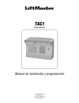
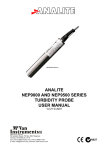
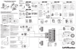
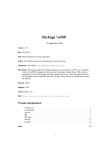
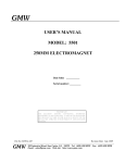
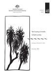
Precision Weather Monitoring Instruments
SYNCHROTAC 706 SERIES.
DATA SHEET AND
INSTALLATION
INSTRUCTIONS
Vers 4.51 © 2005
SYN706 Manual V4_51.indd
abn 56 007 283 963
58 geddes street, Po box 298, Mulgrave
Victoria, austraLIa, 3170
tel: (+61-3) 9582-7333, fax: (+61-3) 9560-1164
e-mail: [email protected], Internet: www.mcvan.com
N827
Precision Weather Monitoring Instruments
SYNCHROTAC
706 SERIES
HEAVY DUTY WIND TRANSMITTER
Synchrotac 706 Series Heavy Duty Wind Speed and Direction Transmitter
Designed for general meteorological applications where accuracy, durability and long term reliability are
required even in severe climatic conditions. The Synchrotac has a long history of reliable service in very
aggresive environments such as in coastal tropical cyclone areas and oil rigs.
Three anemometer models and two wind direction models are available in the Synchrotac 706 series.
The anemometer models available are the 732 - poly-phase linear generator; the 734 - isolated switch
contact closure; and the 736 for opto-electronic pulse output. The wind direction models may be either
the 706 unit - 360° precision potentiometer or the 724 unit utilising a ganged 540° potentiometer
assembly.
The anemometer section may be purchased separately for wind speed only applications.
Series 706 Heavy Duty Wind Speed and Direction Transmitter
General Specifications
The Synchrotac 706 Series Heavy Duty Wind Speed and Direction Transmiters are designed for long trouble free life under
severe climatic conditions. They are solidly constructed from naval bronze, brass, stainless steel and other corrosion resistant
materials. Bearings are low friction stainless steel for a low starting threshold.
The instrument is sealed against dust, moisture and vermin ingress and mounts directly on a 3⁄4 inch (speed only) or 11⁄2 inch (speed
& direction) male BSP thread. Special bearing lubricants ensure reliable operation over the temperature range and, under normal
conditions, should give maintenance free operation in excess of 10 years.
The wind speed section may be any one of three user selected technologies. The type 732 is a ten pole ac generator , the type 734
employs magnetically actuated reed switch(es) and the 736 is an opto-electronic transducer.
Wind direction is also ordered in one of two different configurations. The type 706 is a potentiometric transducer, and the type 724
is a 540° configuration employing two precision potentiometers.
Wind Speed Transmitter Section - General
Cup Diameter
127mm (5”).
Turning Circle Diameter 457mm (18”).
Body Diameter
102mm (4”).
Overall Height
229mm (9”).
Mass of Cup Set
0.95kg. (2.1lbs).
Overall Weight
3kg.
(6.6lbs).
Mounting
3⁄4” BSP Female Thread.
Maximum Wind Speed >100m/sec (>200 knots)
Accuracy
Better than ±3% above 5m/sec.
Transfer Coefficient
0.35 revs/meter
Wind Direction Transmitter Section - General
Vane Length
457mm (18”).
Turning Circle Diameter 914mm (36”).
Body Diameter
109mm (4.25”).
Overall Height
329mm (13”).
Mass of Vane Assembly 1.1kg. (2.4lbs).
Overall Weight
9kg.
(19.8lbs).
Mounting
11⁄2” BSP Female Thread.
Starting Threshold
<0.7m/sec.
Mechanical Travel
360° (continuous).
Operating Temperature -40°C to +60°C.
Type 732 Wind Speed Transducer
Transducer
Permanent magnet 10 pole ac
generator.
Signal Output
136mV/m/sec, and
1.8Hz/m/sec @>3m/sec.
Starting Threshold
<0.7 m/sec.
Output Resistance
22 ohms nominal.
Operating Temperature -40°C to +60°C.
Type 706 Wind Direction Transducer
Transducer
1 kΩ precision potentiometer.
Electrical Travel
Better than 354°.
Max Transducer Voltage 12V dc continuous.
Type 734 Wind Speed Transducer
Transducer
Magnetically actuated reed switch.
Output
Momentary contact closure.
VER 1 single closure per cup set
revolution, VER 2 five closures per
cup set revolution.
ON resistance
8.2 ohms nom.
Starting Threshold
<0.6 m/sec.
Electrical Rating
48Vdc/30Vac, 0.3A max.
Load must be non-inductive.
Operating Temperature -40°C to +60°C.
Type 736 Wind Speed Transducer
Transducer
Opto-electronic.
Output
From 1 to 30 pulses per cup set
revolution either 5V or 1mA (to be
specified at time of order).
Starting Threshold
<0.5 m/sec.
Power Requirements
5.5 - 28V dc, 10mA max.
Operating Temperature -20°C to +60°C.
Type 724 Wind Direction Transducer
Transducer
Two 1 kΩ precision potentiometers
ganged 180° apart.
Electrical Travel
540°.
Max Transducer Voltage 12V dc continuous.
Combined Wind Speed and Direction Sections
Overall Height
558mm (22”).
Overall Weight
12kg. (26.4lbs)
Ordering Information
Wind Speed Only Order SYN732, SYN734 or SYN736 as
required. For SYN734 specify VER1
or VER 2.
Wind Speed & Direction Start with wind direction section and
add wind speed section preceded by
a slash.
Example
SYN706/732
Options
Ordered separately.
Specification subject to change without notice.
SYN706 V9.indd, Nov 2003
INSTALLATION INSTRUCTIONS (full instrument - wind direction and wind speed).
1.
2.
3.
Prepare a mast to appropriate height, with at least 250mm of pipe at top
threaded to 1½” B.S.P. The male thread section must be at least 55mm long.
Screw the supplied large brass locking nut onto the pipe thread to the bottom
of the thread. Feed a suitable cable* with approximately 250mm protruding
from the top of the mast pipe. Ensure that the mast pipe is properly earthed.
Remove the Synchrotac 706 series wind speed and direction transmitter
from its packing being careful not to damage the cup or vane assemblies.
Remove the weather-proof 108mm diameter cover from the wind direction
section by loosening the 3 screw located on its underside, and turning the
cover so that the screw heads pass through the enlarged section of the slotted
holes in the cover’s flange.
Place the wind direction cover over and through the mast pipe so that the
flange is at the bottom, and temporarily tie it to the mast until the unit is
installed and wiring completed.
Cable
(shield trimmed
back)
1.5” BSP
Thread
15 - 10
mm
55mm
Mast
End
Ma
En
Prepare mast end
and cable
Prepa
an
Cable
Mast
End
Ma
En
Large
Locking Nut
4.
Thread the cable up through the B.S.P. female thread fitting at the base of
the wind direction unit. Apply some slow setting thread adhesive to the mast
thread and screw the instrument onto the mast. Use caution as the instrument
is heavy
5.
Bare (or fix male 6.4mm spade connectors to) the necessary number of conductors from the cable
and connect to the terminals at the bottom of the wind direction cartridge keeping note of the colours.
Connection can usually be done using a right-angled screwdriver; if this is not possible, remove the
cartridge for connection as follows:
Fit large looking
nut
Note carefully before the removal of the wind direction cartridge the position of all parts in relation
to each other. Slacken the 4 set screws in the main frame that holds the direction cartridge in position,
but only far enough to allow the clamp and direction cartridge to be lowered and removed. Place the
direction cartridge clamp over the conductors (tapered sides to the bottom). Connect the conductors
and prepare to re-install the cartridge in the same position as before. First note that both the gear and
the direction cartridge have a 3mm hole in the top, and the clamp has a pin attached to it by means
of wire. Rotate the gear on top of the wind direction cartridge so that it lines up with the hole in the
top of the unit. Place the cartridge back in the frame of the unit, making sure that the rubber ring is
in position at the bottom of the cartridge. The holes in the top of the cartridge and the gear should be
opposite the small gear in the top of the wind direction unit. With the balance weight of the vane in the
same position prior to cartridge removal, engage the gears. Place the cartridge clamp in position and
tighten the 4 locking set screws in position so that the rubber ring just compresses. Ensure the cartridge
is held firmly and will not move.
6.
3/4” BSP
Thread
Place the supplied 3mm right-angled pin in the hole in the cartridge gear. To enable this to be done
you will note that to the side of a screw over which the conductors from the wind speed section is
placed, there is a machined section the boss to allow the pin to be installed. Turn the wind direction
vane until the pin locates in the hole in the top cartridge. This now locks the unit in the North position
of the cartridge. Tighten the wind direction unit on the mast (using the 55mm spaced flats on the
bottom mounting hub) and adjust until the vane balance weight points to the North. Lock the unit in
position using the set screw in the threaded portion at the base of the unit. Remove the 3mm pin so
that the vane is free to rotate and let the pin hang down inside the mounting pipe, making sure that it
does not touch the connection terminals. Screw up the brass locking nut and firmly tighten against the
anemometer housing – ensure the housing does not rotate.
Fit ma
pi
7.
Fasten the locking set screw in the base of the wind direction casting onto the mast pipe thread.
8.
Connect the appropriate conductors to the wind speed terminal strip mounted near the bottom of the
main frame. Ensure there is a good earthing contact between the instrument body and the mast pipe.
9.
Replace the weatherproof cover on the unit and tighten the 3 screws. Rotate the vane and make sure it
moves freely.
10.
Fit the cup set assembly to the anemometer shaft. The cup set hub is supplied with two M5 set screws.
Ensure the set screw in the cup set hub is in line with the flat on the anemometer shaft and seated
in the circular depression on the shaft. Firmly tighten the first set screw. Screw in the second set
screw and tighten. If the cup hub and the shaft are properly aligned the end of the second grubscrew
will be just below the surface of the cup hub. Apply a little thread adhesive to the thread of the second
setscrew.
11.
Test the unit for proper peformance. Ensure there is a good earthing contact between the instrument
body and the mast pipe.
12.
If properly installed, the Synchrotac 706 series wind speed and direction transmitter should require no
maintenance for many years.
*
The characteristics of a suitable cable is dependant on the instrument used and the application
environment. As a minimum the cable should contain at least 2 cores for the SYN732 and 734, 3
cores for the SYN736, 5 cores for the SYN706/732 and SYN706/734 and 6 cores for the SYN706/
736 although a few spare cores is recommended. The conductor core should be overall shielded with
the shield terminated at the logger/indicator end only. The cable should be a low capacitive type
particularly for installations containing the SYN734 anemometer version. High cable capacitance can
shorten the life of the reed switch units in the SYN734 due to the high current discharge it may cause
each time the switch closes - a limiting resistor is installed in the SYN734 to assist in the protection of
the reed switches contained therein.
SAFETY NOTE:
To ensure the instrument remains properly installed in service make sure a suitable
and quality thread adhesive is used where stipulated. Failure to do so may result in
the instrument or on of its components working loose under conditions of prolonged
thermal or mechanical stress.
Screw on locking
nut before fitting
anemometer to the
pipe. Tighten
locking nut against
the anemometer
base once it has
been fitted and
aligned.
DATE
B 78/96 1/4/96
C 80/02 13/8/02
D 58/03 26/6/03
IS. C/N
Mounting
Pipe with
male 1.5" BSP
Thread x 55mm
(by others)
Pass cable through
mounting pipe and
into housing.
Locking Set Screw
55mm spaced
flats for tightening
and aligning to mast.
Wind Speed
Terminals
Wind Direction
Terminals
Mainframe
Housing
Casting
Fuse
63mA
2
1kohms
W
3
CCW
Unless otherwise stated.
Lin ±0.2mm,
Ang ±0.5°.
Tolerances:
Output
AC2
or
SW2
DC Supply
DRN JVdV
APP KH
P
Status
25/3/96 SHEET SCALE DWG No. ISS
D
3285
25/3/96 1 OF 1 NTS
SYNCHROTAC 706 INSTALLATION
TERMINATION DETAILS
2002
C Copyright
SYN736
Anemometer section
SYN732 and SYN734
Anemometer section
File: SYN706 Termination Details.cdr
Common
Red
Blue
White Black
AC1
or
SW1
Blue
DIRECTION CARTRIDGE
LOOKING AT BASE
1
CW
INSTALLATION INSTRUCTIONS (anemometer section only - SYN732/734/736).
1.
Prepare a mast to appropriate height, with at least 250mm
of
Cable
(shield trimmed
pipe at top threaded to 3/4” B.S.P. The
male
thread
section
1.5” BSP
back)
Thread
must be at least 20mm long. Feed a suitable
cable* with
55mm the top of the mast pipe.
approximately 250mm protruding from
Ensure that the mast pipe is properly earthed.
Mast
End
2.
Remove the anemometer body and cup set assembly from its
packing being careful not to damage the cup set assembly.
3.
and cable
Remove the mating female connector and put
aside. Separate
the bottom half of the 3/4” union at the base of the
Cable a
anemometer body and tightly fit it to the mast pipe, using
thread adhesive. Ensure the cable is threaded through the union
base.
Prepare mast end
4.
The mating female connector should be properly
terminated to
Mast
the cable protruding from the top of the mastEndpipe.
5.
Mate the female connector into the plug at the base ofLocking Nut
Fit large
lookingthe
the anemometer body. Care should be taken
to ensure
nut
connectors are properly mated. The pins are numbered and
keyed.
Large
Cable
(shield trimmed
back)
3/4” BSP
Thread
15 - 10
mm
Mast
End
Prepare mast end
and cable
Cable
Mast
End
Male Union
Piece
Fit male union
piece
6.
Apply some (breakable) thread adhesive to the male union thread. Place the anemometer body
onto its mating union half on the mast and fasten the union nut tightly. Fasten the M5 hex set
screw in the union nut.
7.
Fit the cup set assembly to the anemometer shaft. The cup set hub is supplied with two M5 set screws.
Ensure the set screw in the cup set hub is in line with the flat on the anemometer shaft and seated
in the circular depression on the shaft. Firmly tighten the first set screw. Apply a little (breakable)
thread adhesive to the thread of the second setscrew, insert behind the first set screw and tighten. If
the cup hub and the shaft are properly aligned the end of the second grubscrew will be just below the
surface of the cup hub.
8.
Test the anemometer for proper peformance. Ensure there is a good earthing contact between the
anemometer body and the mast pipe.
9.
If properly installed, the Synchrotac 706 series wind speed transmitter should require no maintenance
for many years.
*
The characteristics of a suitable cable is dependant on the instrument used and the application
environment. As a minimum the cable should contain at least 2 cores for the SYN732 and 734, 3
cores for the SYN736, 5 cores for the SYN706/732 and SYN706/734 and 6 cores for the SYN706/
736 although a few spare cores is recommended. The conductor core should be overall shielded with
the shield terminated at the logger/indicator end only. The cable should be a low capacitive type
particularly for installations containing the SYN734 anemometer version. High cable capacitance can
shorten the life of the reed switch units in the SYN734 due to the high current discharge it may cause
each time the switch closes - a limiting resistor is installed in the SYN734 to assist in the protection of
the reed switches contained therein.
SAFETY NOTE:
To ensure the instrument remains properly installed in service make sure a suitable
and quality thread adhesive is used where stipulated. Failure to do so may result in
the instrument or on of its components working loose under conditions of prolonged
thermal or mechanical stress.
Note:
Reed switch life can be adversely affected by
long cable runs due to cable capacitance and
inductive loads. Use low capacitance cable
where ever possible and ensure the end load is
resistive.
VER 2
(5 switches)
IS
C/N
Reed Switch
50V ac/dc rating
0.5Amp non-inductive.
DATE
Unless otherwise
stated.
Lin ±0.5mm
Ang±0.5°Ang
Tolerances
VER 1
(one switch only)
2
2
3
24/11/03 SHEET
1 OF 1
C
SCALE DWG No ISS
NTS
A
TBA
© 2003
Viewed looking at the
base of the Anemometer
1
Status
MAX 48V dc
MAX 30V ac
MAX 0.3Amp
1
Connector at
base of anemometer
Sw2
MOV
S10K30
SYN734 Anemometer
Circuit Schematic
DRN KH
APP
8.2 ohms
1 watt WW
Sw1
Precision Weather Monitoring Instruments
APPLICATION NOTE
Positioning of Wind Speed Instruments
The World Meteorological Organisation (WMO) states that an anemometer for the purpose of measuring surface winds should be
mounted 10 metres above the ground as a standard.
Ideally, measurements should be made on level, open terrain, but since such conditions rarely exist, certain guide-lines may be
followed should obstructions or other problems related to exposure exist.
Locating Instruments on or near Structures
Generally accepted guide-lines for locating wind systems around an obstruction while keeping instruments in the ambient airflow.
1.
•
•
•
For structures up to 10 metres in height.
Locate instrument generally upwind of a structure at a distance away equal to the structure’s height.
Locate instrument on top of the structure at a height of the structure above the structure.
Locate instrument a distance generally downwind of structure equal to 5-10 times the structure height.
2.
•
•
For structures in excess of 10 metres height.
Placing instruments on top of very small structures presents some difficulties. Whenever possible it is best to erect
a tower to clear any obstructions. In the case of a building where a tower may not be practical, an alternative is to
place the instrument on a corner of the building that is generally upwind, or the corner, which is exposed to the
frequency of the wind.
Before making a permanent installation monitor a small flag at the end of a pole mounted in various locations on the
building, to assist in determining the location which is most representative.
In a flat open rural area an installation of 2 metres height may be sufficient.
File: Wind Application Note 1.doc
abn 56 007 283 963
58 geddes street, Po box 298, Mulgrave
Victoria, austraLIa, 3170
tel: (+61-3) 9582-7333, fax: (+61-3) 9560-1164
e-mail: [email protected], Internet: www.mcvan.com
EC Declaration of Conformity
according to Council Directive 89/336/EEC
We, McVan Instruments Pty Ltd, declare under our sole responsibility
that the productS:
SYNCHROTAC 706 SERIES WIND INSTRUMENTS
SYN732, SYN734V1, SYN734V2, SYN736
SYN706/732, SYN706/734V1, SYN706/734V2, SYN706/736
SYN724/732, SYN724/734V1, SYN724/734V2, SYN724/736
Manufactured by:
McVan Instruments Pty Ltd
To which this declaration relates, are in conformity with the
protection requirements of council directives 89/336/eec on the
approximation of the laws relating to electromagnetic compatibly.
This Declaration of Conformity is based upon compliance of the
product with the following harmonised standards:
Emissions:EN50081-1 using EN55022 class B.
Immunity:EN50082-1 using IEC61000-4-2, IEC61000-4-3, IEC61000-4-4
and IEC61000-4-6.
Signed by:
John Van de Vreede – Director.
Date of Issue:
1 DECEMBER 2003.
Place of Issue:
McVan Instruments Pty Ltd
58 Geddes Street, Mulgrave
Vic. 3170 Australia.
abn 56 007 283 963
58 geddes street, Po box 298, Mulgrave
Victoria, austraLIa, 3170
tel: (+61-3) 9582-7333, fax: (+61-3) 9560-1164
e-mail: [email protected], Internet: www.mcvan.com
N827
NOTES
abn 56 007 283 963
58 geddes street, Po box 298, Mulgrave
Victoria, austraLIa, 3170
tel: (+61-3) 9582-7333, fax: (+61-3) 9560-1164
e-mail: [email protected], Internet: www.mcvan.com