1
®
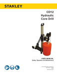
User’s Manual
HYDRAULIC
CORE DRILL
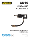
CD10
DANGER
SERIOUS INJURY OR DEATH COULD RESULT
FROM THE IMPROPER REPAIR OR SERVICE OF
THIS TOOL.
Copyright © 2001 The Stanley Works
OPS USA & CE Version
58858 9/2002 Ver. 1 Stanley
REPAIRS AND/OR SERVICE TO THIS TOOL
MUST ONLY BE DONE BY AN AUTHORIZED AND
CERTIFIED DEALER.
Table of Contents
CD10
CORE DRILL
SERVICING THE
CD10 CORE DRILL :
This manual contains Safety,
Operation, and Troubleshooting
information. Stanley Hydraulic Tools
recommends that servicing of
hydraulic tools, other than routine
maintenance, must be performed
by an authorized and certified
dealer. Please read the DANGER
warning on the cover and the
Copyright © 2001 The Stanley Works
All rights reserved.
Under copyright law, this document may
not be copied in whole or in part without
the prior written consent of The Stanley
Works. This exception does not permit
copies to be made for others, whether or
not sold. Under the law, copying includes
translating into another language, format
or medium. This copyright notice must
appear on any permitted copies.
2
Specifications
3
General Safety Instructions
4
Tools Decals and Tags
5
Hydraulic Hose Requirements
6
HTMA Requirements
7
Operating Instructions
8
Troubleshooting
11
Maintenance
14
Parts Illustration
15
Parts List
16
Accessories
19
Warranty
20
SAFETY FIRST
It is the responsibility of the operator and
service technician to read rules and
instructions for safe and proper operation and
maintenance.
A cautious worker using common sense is the
greatest safety device.
Specifications
Pressure__________________2000 psi / 140 bar
Hydraulic Connection__Quick Couplers 1/2 in. FF
Water Pressure_____________max. 60 psi / 4 bar
Hose Diameter_______________.500 in. / 12 mm
Maximum Back Pressure_______250 psi/ 17 bar
HTMA Class I____________4-6 gpm @ 2000 psi
Weight_____________________18.7 lbs. / 8.5 kg
C
20Lpm at 138bar
BHTMA CATEGORY
EHTMA Category_____20 lpm @138 bar
Overall Length_______________19.3 in. / 490 mm
HTMA Class II___________7-9 gpm @ 2000 psi
Max. Fluid Temp._____________140° F / 60° C
30Lpm at 138bar
BHTMA CATEGORY
EHTMA Category_____30 lpm @ 138 bar
Capacity_____________________3.6 hp / 2.8 kW
Flow Range______________5-13 gpm / 20-50 lpm
Sound Pressure _______________80 dBA @ 1m.
Maximum Flow_______________13 gpm / 49 lpm
Vibration Level___________________0.82 m / s
2
Porting______________________-8 SAE O-ring
Water Connection____________Gardena System
Free Speed______________1st Gear - 380 rpm
2nd Gear - 900 rpm
3rd Gear - 1800 rpm
Drill Bit Connection_____1 - 1/4 in. UNC male / R
1/2 in. Female
3
General Safety Instructions
Always observe safety symbols. They are included for your safety and the protection of the tool.
DANGER
This safety symbol may appear on
the tool. It is used to alert the
operator of an action that could
place him/her or others in a life
threatening situation.
CAUTION
WARNING
This safety symbol appears in these
instructions to identify an action
that could cause bodily injury to the
operator or other personnel.
This safety symbol appears in these
instructions to identify an action or
condition that could result in
damage to the tool or other
equipment.
This tool will provide safe and dependable service if operated in accordance with the instructions
given in this manual. Read and understand this manual and any stickers and tags attached to the
tool and hoses before operation. Failure to do so could result in personal injury or equipment
damage.
A
Operator must start in a work area without bystanders. The operator must be familiar with all prohibited work
areas such as excessive slopes and dangerous terrain conditions.
A
Establish a training program for all operators to ensure safe operations.
A
Do not operate the tool unless thoroughly trained or under the supervision of an instructor.
A
Always wear safety equipment such as goggles, head protection, and safety shoes at all times when operating
the tool.
A
Do not inspect or clean the tool while the hydraulic power source is connected. Accidental engagement of the
tool can cause serious injury.
A
Do not operate this tool without first reading the Operating Instructions.
A
Do not install or remove this tool while the hydraulic power source is connected. Accidental engagement of
the tool can cause serious injury.
A
Never operate the tool if you cannot be sure that underground utilities are not present. Underground electrical
utilities present an electrocution hazard. Underground gas utilities present an explosion hazard. Other
underground utilities may present other hazards.
A
Do not wear loose fitting clothing when operating the tool. Loose fitting clothing can get entangled with the
tool and cause serious injury.
A
Supply hoses must have a minimum working pressure rating of 2500 psi/175 bar.
A
Be sure all hose connections are tight.
A
The hydraulic circuit control valve must be in the “OFF” position when coupling or uncoupling the tool. Wipe
all couplers clean before connecting. Failure to do so may result in damage to the quick couplers and cause
overheating. Use only lint-free cloths.
A
Do not operate the tool at oil temperatures above 140° F/60° C. Operation at higher oil temperatures can
cause operator discomfort and may cause damage to the tool.
A
Do not operate a damaged, improperly adjusted, or incompletely assembled tool.
A
To avoid personal injury or equipment damage, all tool repair, maintenance and service must only be
performed by authorized and properly trained personnel.
A
Do not exceed the rated limits of the tool or use the tool for applications beyond its design capacity.
A
Always keep critical tool markings, such as labels and warning stickers legible.
A
Always replace parts with replacement parts recommended by Stanley Hydraulic Tools.
A
Check fastener tightness often and before each use daily.
4
Tool Decals & Tags
A Name Tag Sticker is attached to the tool. Never exceed the flow and pressure levels specified on
this sticker.The information listed on the name tag sticker must be legible at all times. Replace this
sticker if it becomes worn or damaged. A replacement is available from your local Stanley
distributor.
28409
Composite Sticker
Location Model # / SN
C
20Lpm at 138bar
BHTMA CATEGORY
30Lpm at 138bar
BHTMA CATEGORY
CD10 Name Tag & GPM Sticker
44968
11206
Circuit Type “C” Decal
DANGER
11207
Circuit Type “D” Decal
The SAFETY TAG, P/N 15875, shown at right, smaller
than actual size, is attached to the tool when shipped
from the factory. Read and understand the safety
instructions listed on this tag before removal. We
suggest you retain this tag and attach it to the tool
when not in use.
DANGER
1. FAILURE TO USE HYDRAULIC HOSE LABELED AND
CERTI-FIED AS NON-CONDUCTIVE WHEN USING
HYDRAULIC TOOLS ON OR NEAR ELECTRICAL LINES
MAY RESULT IN DEATH OR SERIOUS INJURY.
BEFORE USING HOSE LABELED AND CERTIFIED AS
NON- CONDUCTIVE ON OR NEAR ELECTRIC LINES.
BE SURE THE HOSE IS MAINTAINED AS NON- CONDUC TIVE . THE
HOSE SHOULD BE REGULARLY TESTED FOR ELECTRIC CURRENT
LEAKAGE IN ACCORDANCE WITH YOUR SAFETY DEPARTMENT
INSTRUCTIONS.
2. A HYDRAULIC LEAK OR BURST MAY CAUSE OIL
INJECTION INTO THE BODY OR CAUSE OTHER SEVERE PERSONAL
INJURY.
A.DO NOT EXCEED SPECIFIED FLOW AND
PRESSURE FOR THIS TOOL. EXCESS FLOW OR
PRESSURE MAY CAUSE A LEAK OR BURST.
B. DO NOT EXCEED RATED WORKING PRESSURE
OF HYDRAULIC HOSE USED WITH THIS TOOL.
EXCESS PRESSURE MAY CAUSE A LEAK OR
BURST.
C. C H E C K T O O L , H O S E , C O U P L E R S &
C O N N E C T O R S
D A I L Y
F O R
LEAKS. DO NOT FEEL FOR LEAKS WITH
YOUR HANDS. CONTACT WITH A LEAK MAY
RESULT IN SEVERE PERSONAL INJURY.
D. DO NOT LIFT OR CARRY TOOL BY THE HOSES. DO NOT ABUSE
HOSE. DO NOT USE KINKED, TORN OR DAMAGED HOSES.
3. MAKE SURE HYDRAULIC HOSES ARE PROPERLY
CONN-ECTED TO THE TOOL BEFORE PRESSURIZING
SYSTEM. SYSTEM PRESSURE HOSE MUST ALWAYS
BE CONNECTED TO TOOL “IN” PORT. SYSTEM
RETURN HOSE MUST ALWAYS BE CONNECTED AT
TOOL “OUT” PORT. REVERSING CONNECTIONS MAY
CAUSE REVERSE TOOL OPERATION WHICH CAN
CAUSE SEVERE PERSONAL INJURY.
4. DO NOT CONNECT CLOSED-CENTER TOOLS TO
OPEN-CENTER HYDRAULIC SYSTEMS. THIS MAY
CAUSE EXTREME SYSTEM HEAT AND/OR SEVERE
PERSONAL INJURY.
DO NOT CONNECT OPEN-CENTER TOOLS TO CLO SE D- CE NT ER
HYDRAULIC SYSTEMS. THIS MAY RESULT IN LOSS OF OTHER
HYDRAULIC FUNCTIONS POWERED BY THE SAME SYSTEM AND/OR
SEVERE PERSONAL INJURY.
5. BYSTANDERS MAY BE INJURED IN YOUR WORK
AREA. KEEP BYSTANDERS CLEAR OF YOUR WORK
AREA.
6. WEAR HEARING, EYE, FOOT, HAND AND HEAD PROTECTION.
7. TO AVOID PERSONAL INJURY OR EQUIPMENT DAMAGE, ALL TOOL
REPAIR, MAINTENANCE AND
SERVICE MUST BE
PERFORMED BY AUTHORIZED
AN D PR OP ER LY
TRAINED PERSONNEL.
IMPORTANT
IMPORTANT
READ OPERATION MANUAL AND
SAFETY INSTRUCTIONS FOR THIS
TOOL BEFORE USING IT.
READ OPERATION MANUAL AND
SAFETY INSTRUCTIONS FOR THIS
TOOL BEFORE USING IT.
USE ONLY PARTS AND REPAIR
PROCEDURES APPROVED BY
STANLEY AND DESCRIBED IN THE
OPERATION MANUAL.
USE ONLY PARTS AND REPAIR
PROCEDURES APPROVED BY
STANLEY AND DESCRIBED IN THE
OPERATION MANUAL.
TAG TO BE REMOVED ONLY BY TOOL
OPERATOR.
(517)
SEE OTHER SIDE
15875
TAG TO BE REMOVED ONLY BY TOOL
OPERATOR.
(517)
SEE OTHER SIDE
15875
5
Hydraulic Hose Requirements
HOSE TYPES
Hydraulic hose types authorized for use with Stanley Hydraulic Tools are as follows:
Certified non-conductive
Wire-braided (conductive)
Fabric-braided (not certified or labeled non-conductive)
Hose listed above is the only hose authorized for use near electrical conductors.
Hoses and listed above are conductive and must never be near electrical conductors.
HOSE SAFETY TAGS
To help ensure your safety, the following DANGER tags are attached to all hoses purchased from Stanley
Hydraulic Tools. DO NOT REMOVE THESE TAGS.
If the information in a tag is illegible because of wear or damage, replace the tag immediately. A new tag
may be obtained at no charge from your Stanley Distributor.
This Tag attached to “Certified Non-Conductive” hose.
DANGER
1. FAILURE TO USE HYDRAULIC HOSE LABELED AND CERTIFIED AS NON-CONDUCTIVE WHEN USING
HYDRAULIC TOOLS ON OR NEAR ELECTRIC LINES MAY RESULT IN DEATH OR SERIOUS INJURY.
FOR PROPER AND SAFE OPERATION, MAKE SURE THAT YOU HAVE BEEN PROPERLY TRAINED IN
CORRECT PROCEDURES REQUIRED FOR WORK ON OR AROUND ELECTRIC LINES.
2. BEFORE USING HYDRAULIC HOSE LABELED AND CERTIFIED AS NON-CONDUCTIVE ON OR NEAR
ELECTRIC LINES, WIPE THE ENTIRE LENGTH OF THE HOSE AND FITTINGS WITH A CLEAN,
DRY, ABSORBENT CLOTH TO REMOVE DIRT AND MOISTURE AND TEST HOSE FOR MAXIMUM
ALLOWABLE CURRENT LEAKAGE IN ACCORDANCE WITH SAFETY DEPARTMENT INSTRUCTIONS.
DANGER
4. HANDLE AND ROUTE HOSE CAREFULLY TO AVOID KINKING, ABRASION, CUTTING OR CONTACT
WITH HIGH TEMPERATURE SURFACES. DO NOT USE IF KINKED. DO NOT USE HOSE TO PULL OR
LIFT TOOLS, POWER UNITS, ETC.
5. CHECK ENTIRE HOSE FOR CUTS, CRACKS, LEAKS, ABRASIONS, BULGES OR DAMAGE TO
COUPLINGS. IF ANY OF THESE CONDITIONS EXIST, REPLACE THE HOSE IMMEDIATELY.
NEVER USE TAPE OR ANY DEVICE TO ATTEMPT TO MEND THE HOSE.
6.
AFTER EACH USE, STORE IN A CLEAN, DRY AREA.
3. DO NOT EXCEED HOSE WORKING PRESSURE OR ABUSE HOSE. IMPROPER USE OR HANDLING OF
HOSE COULD RESULT IN BURST OR OTHER HOSE FAILURE. KEEP HOSE AS FAR AWAY AS
POSSIBLE FROM BODY AND DO NOT PERMIT DIRECT CONTACT DURING USE. CONTACT AT THE
BURST CAN CAUSE BODILY INJECTION AND SEVERE PERSONAL INJURY.
SEE OTHER SIDE
SEE OTHER SIDE
Side 1
Side 2
DO NOT REMOVE THIS TAG
DO NOT REMOVE THIS TAG
(shown smaller than actual size) p/n 27987
This Tag attached to “Conductive” hose.
DANGER
DANGER
1. DO NOT USE THIS HYDRAULIC HOSE ON OR NEAR ELECTRIC LINES. THIS HOSE IS NOT
LABELED OR CERTIFIED AS NON-CONDUCTIVE. USING THIS HOSE ON OR NEAR ELECTRIC LINES
MAY RESULT IN DEATH OR SERIOUS INJURY.
5. CHECK ENTIRE HOSE FOR CUTS, CRACKS, LEAKS, ABRASIONS, BULGES OR DAMAGE TO
COUPLINGS. IF ANY OF THESE CONDITIONS EXIST, REPLACE THE HOSE IMMEDIATELY.
NEVER USE TAPE OR ANY DEVICE TO ATTEMPT TO MEND THE HOSE.
2. FOR PROPER AND SAFE OPERATION, MAKE SURE THAT YOU HAVE BEEN PROPERLY TRAINED IN
CORRECT PROCEDURES REQUIRED FOR WORK ON OR AROUND ELECTRIC LINES.
6.
AFTER EACH USE, STORE IN A CLEAN, DRY AREA.
3. DO NOT EXCEED HOSE WORKING PRESSURE OR ABUSE HOSE. IMPROPER USE OR HANDLING OF
HOSE COULD RESULT IN BURST OR OTHER HOSE FAILURE. KEEP HOSE AS FAR AWAY AS
POSSIBLE FROM BODY AND DO NOT PERMIT CONTACT DURING USE. CONTACT AT THE
BURST CAN CAUSE BODILY INJECTION AND SEVERE PERSONAL INJURY.
4. HANDLE AND ROUTE HOSE CAREFULLY TO AVOID KINKING, ABRASION, CUTTING OR CONTACT
WITH HIGH TEMPERATURE SURFACES. DO NOT USE IF KINKED. DO NOT USE HOSE TO PULL OR
LIFT TOOLS, POWER UNITS, ETC.
SEE OTHER SIDE
SEE OTHER SIDE
Side 1
Side 2
DO NOT REMOVE THIS TAG
DO NOT REMOVE THIS TAG
(shown smaller than actual size) p/n 29144
HOSE PRESSURE RATING
The rated working pressure of the hydraulic hose must be equal to or higher than the relief valve setting on
the hydraulic system.
6
HTMA Requirements
Hydraulic System
Requirements
Tool
Category:
Flow rate
Tool Operating Pressure
C
20Lpm at 138bar
BHTMA CATEGORY
30Lpm at 138bar
BHTMA CATEGORY
Type I
Type II
Type III
4-6 GPM (15-23 lpm)
2000 psi (138 bar)
7-9 GPM (26-34 lpm)
2000 psi (138 bar)
11-13 GPM (42-49 lpm)
2000 psi (138 bar)
2100-2250
2100-2250
2100-2250
(145-155 bar)
(145-155 bar)
(145-155 bar)
250 psi
250 psi
250 psi
(17 bar)
(17 bar)
(17 bar)
(at min. operating temperature)
400 SSU
400 SSU
400 SSU
(82 centistokes)
(82 centistokes)
(82 centistokes)
Temperature
Sufficient heat rejection capacity
to limit max. fluid temperature to:
140° F (60° C)
140° F (60° C)
140° F (60° C)
3 hp (2.24 kW)
40° F (22° C)
5 hp (3.73 kW)
40° F (22° C)
7 hp (5.22 kW)
40° F (22° C)
(at the power supply outlet)
System relief valve setting
(at the power supply outlet)
Maximum back pressure
(at tool end of the return hose)
Measured at a max. fluid viscosity of:
(at max. expected ambient temperature)
Min. cooling capacity
at a temperature difference of
between ambient and fluid temps
NOTE: Do not operate the tool at oil temperatures above 140° F (60° C). Operation at higher temperatures can cause operator
discomfort at the tool.
Filter
Min. full-flow filtration
sized for flow of at least:
25 microns
30 GPM (114 lpm)
25 microns
30 GPM (114 lpm)
25 microns
30 GPM (114 lpm)
100-400 SSU*
100-400 SSU*
100-400 SSU*
(20-82 centistokes)
(20-82 centistokes)
(20-82 centistokes)
(For cold temp. startup and max. dirt-holding capacity)
Hydraulic fluid
Petroleum based
(premium grade, anti-wear, non-conductive)
Viscosity
(at min. and max. operating temps)
NOTE: When choosing hydraulic fluid, the expected oil temperature extremes that will be experienced in service determine the
most suitable temperature viscosity characteristics. Hydraulic fluids with a viscosity index over 140 will meet the requirements over
a wide range of operating temperatures.
*SSU = Saybolt Seconds Universal
NOTE: These are general hydraulic system requirements. See tool Specification page for
tool specific requirements.
7
Operating Instructions
General Operation
Check the Power Source
The tool comes with a set of accessories which
may be customized by each purchaser, so as to
facilitate performance of all work occurring
within the scope of his specific application. Tools
included are for mounting and dismounting.
1. Using a calibrated flowmeter and pressure
gauge, check that the hydraulic power source
develops a flow of 5.8-13.2 gpm / 22-50 lpm
at 950-2000 psi / 66-140 bar.
2. Make certain that the hydraulic power source
is equipped with a relief valve set to open at
2100-2250 psi / 145-155 bar.
• single-head wrench
SW24
• single-head wrench
SW32
• single-head wrench
SW 41
3. Check that the hydraulic circuit matches the
tool for open-center (OC) operation.
• hex wrench
SW 5
Check the Tool
Basically, you differentiate between freehand
drilling and stand-aided drilling. The operating
procedures to be adhered to for the two different
operating modes are described below.
1. Make certain all tool accessories are correctly
installed. Failure to install tool accessories
properly can result in damage to the tool or
personal injury.
Drill Bit Installation
2. There should be no signs of leaks.
3. The tool should be clean and dry with all
fittings and fasteners tight.
WARNING
Before you start changing the drill bit, make sure that
the tool is disconnected from the power source in order
to avoid unintentional operation of the tool and injury.
Disconnect only unpressurized hoses.
Use a single-head wrench SW 24 (small drill bit)
or SW 41 (large drill bits) and a single-head
wrench SW 32 to manually unscrew the drill bit
to be removed and to screw on the new one. There
is no need to use any additional tools.
Dimension of the Drill Bit
Drill head thread: male 1 - 1/4 in. UNC and female
R 1/2 in.
Which drill bit at which speed?
speed [1/min]
drill bit diameter [mm]
cutting speed [m/s]
8
gear #1
380
100 - 162
2 - 3,5
gear #2
900
40 - 100
2 - 4,5
gear #3
1800
20 - 40
2-4
Connect Hoses
1. Wipe all hose couplers with a clean lint-free
cloth before making connections.
2. Connect the hoses from the hydraulic power
source to the tool fittings or quick disconnects.
Connect the return hose first and disconnect it
last to eliminate or reduce trapped pressure for
easier quick-connect fitting attachment.
NOTE: If uncoupled hoses are left in the sun,
pressure increase within the hoses can make
them difficult to connect. When ever possible,
connect the free ends of hoses together.
3. Observe the flow indicators stamped on the
hose couplers to ensure that the flow is in the
proper direction. The female coupler on the
tool's IN port is the inlet coupler.
Operating Instructions
4. Squeeze the drill trigger momentarily. If the
drill does not operate, the hoses might be
reversed. Verify correct connection of the
hoses before continuing.
Freehand Drilling
1. Observe all safety precautions.
2. Mount the spot-drilling aid onto the centering
collar to ensure precise positioning.
3. Screw on the desired drill bit (up to max. Ø 80
mm approx. 3 inches). Refer to the DRILL
BIT INSTALLATION for details. Manual
tightening is sufficient because the drill bit
will automatically fasten further during
drilling.
4. Connect the tool to water supply. For this
purpose the device comes with a 10 liter pump
barrel, which has to be pressurized first. You
may alternatively connect the device to a
water tap, using the "Gardena" hose
couplings. Maximum water pressure is
60 psi / 4 bar.
5. Finally connect the tool to the power source.
6. Move the hydraulic circuit control valve to the
ON position.
7. Regulate the water valve to adjust the water
supply flow as desired.
8. With the so prepared drill, you may now
proceed to carry out your work.
CAUTION
Never switch into gear #1 in freehand drilling operation.
This delivers the highest torque.
9. Put the drill in drilling position and squeeze
the trigger to activate the drill.
10. Release the trigger to stop the drill.
WARNING
To avoid injury, do not use the valve trigger lock in
freehand drilling operation! Use valve trigger lock in
stand-aided drilling operation only!
11. The handle and the spot-drilling aid enable
controlled manual operation of the drill.
CAUTION
Monitor continuously the water supply to ensure that
sufficient water is supplied to the cut surface to avoid
unnecessary wear of drilling equipment.
12. To change drill bits, proceed as described
above. Adhere to safety instructions!
13. For dismounting the drill upon completion of
drilling work, follow the mounting
instructions in reverse order.
Stand-aided Drilling
First, fix the stand at the point where you wish to
drill the opening or hole. To do so, drill a hole
matching the size of the corresponding screw
anchor screw the stand onto the surface. Align the
stand such that the drill bit will make contact with
the surface precisely at the point where you want
to drill the opening or hole.
1. Insert the drill from above into the
corresponding seat and fasten the core drill by
means of the hex head socket wrench SW 5.
2. Now, manually screw the corresponding drill
bit from below onto the drill bit adapter.
Manual tightening is sufficient because the
drill bit will automatically fasten further
during drilling operation.
3. If necessary to attain an angled drill hole,
adjust the stand position by swiveling the arm
of the stand.
4. Connect the tool to water supply. For this
purpose the device comes with a 10 liter pump
9
Operating Instructions
barrel, which has to be pressurized first. You
may alternatively connect the device to a
water tap, using the "Gardena" hose
couplings. Maximum water pressure is
60 psi / 4 bar.
5. Finally connect the tool to the power source.
6. Move the hydraulic circuit control valve to the
ON position.
7. To operate the drill, regulate check valve to
adjust the water supply flow as desired.
8. With the so prepared drill, you may now
proceed to carry out your work.
9. Squeeze the trigger to activate the drill and
press valve trigger fixing key to ensure
comfortable working.
CAUTION
Monitor continuously the water supply to ensure that
sufficient water is supplied to the cut surface to avoid
unnecessary wear of drilling equipment.
10. You may continuously control the advance
motion of the drill by adjusting the star knob
at the side of the drilling stand.
11. To switch off the machine, unlock the valve
trigger fixing key. Then, shut off the water
supply.
12. To change drill bits, proceed as described
above. Adhere to safety instructions!
13. For dismounting the drill upon completion of
drilling work, follow the mounting
instructions in reverse order.
10
CAUTION
When drilling into a structure that might contain
electrical wiring, be sure to know the location of the
wiring and avoid drilling into it. The housing can carry
electrical current from live electrical wires into which
the drill is accidentally drilled resulting in injury or
death.
Cold Weather Operation
If the drill is to be used during cold weather,
preheat the hydraulic fluid at low engine speed.
When using the normally recommended fluids,
fluid temperature should be at or above
50 °F/10 °C (400 ssu/ 82 centistokes) before use.
Damage to the hydraulic system or drill can result
from use with fluid that is too viscous or too thick.
Troubleshooting
This section describes how to find and resolve problems users may experience. If a situation occurs that is not covered,
call your Stanley Customer Service representative for assistance.
WARNING
Inspecting the tool or installing parts with the hydraulic hoses connected can result in severe personal injury or equipment
damage.
To prevent accidental startup, disconnect the hydraulic power before beginning any inspection or installation task.
If symptoms of poor performance develop, the following chart can be used as a guide to correct the problem.
When diagnosing faults in operation of the tool, always check that the hydraulic power source is supplying the correct
hydraulic flow and pressure to the tool as listed in the table. Use a flowmeter known to be accurate. Check the flow
with the hydraulic oil temperature at least 80° F/27° C.
Symptom
Tool will not start.
Possible Cause
Power not being supplied.
Solution
Check to make certain that both
hoses are connected.
Turn hydraulic circuit control valve
ON.
Defective quick disconnect
Check each disconnect separately.
Replace as necessary.
Jammed motor.
See your authorized dealer for
service.
Flow reversed through hoses.
Correct the power source control
valve position. Prevent reverse flow
by using only one port from the
valve for pressure, the return tool
hose to the cooler and the filter line.
Correct the quick-disconnect male/
female routing per instructions and
the arrows on the fittings.
Low drilling torque. Incorrect hydraulic flow.
Check that the hydraulic power
source is producing 5.8-13-2 gpm /
22-50 lpm at 950-2000 psi /
66-140 bar.
Defective quick disconnect.
Check each disconnect separately.
Hydraulic circuit relief set too low,
hoses too restrictive or the
hydraulic fluid is too thick.
Set relief valve at 2100 psi / 145 bar.
Fluid Restriction in hose or valve.
Excess back pressure.
Locate and remove restrictions.
Use correct fluid.
continued
11
Troubleshooting
Symptom
Possible Cause
Low drilling torque. Fluid Restriction in hose or valve.
continued
Excess back pressure.
continued
Tool runs too fast.
Trigger operation
erratic.
Control difficult.
Solution
Fluid not warmed-up. Preheat
system.
Hoses too long for hose I.D. Use
shorter hose.
Priority flow control valve is
malfunctioning.
See your authorized service dealer
for replacement.
Flow reversed through hoses.
Correct the power source control
valve position. Prevent reverse flow
by using only one port from the
valve for pressure, the return tool
hose to the cooler and the filter line.
Correct the quick-disconnect male/
female routing per instructions and
the arrows on the fittings.
Too low slip clutch torque.
Inspect and replace slip clutch
washers if necessary. Set torque to
20±1,5 Nm, 15±1 lbf.ft. See your
authorized service dealer for repair.
Do not overload drill to avoid wear
of slip clutch.
Incorrect hydraulic flow.
Check that hydraulic power source
is not producing over 13.2 / 50 lpm
at 950-2000 psi / 66-149 bar.
Hydraulic flow reversed.
Correct the tool hoses, IN and OUT
per instructions and if the power
supply valve is reversible, reconnect
the tool return hose to the oil cooler
or to the filter directly.
Priority valve faulty.
Do not separate modules. Remove
inspect and replace priority valve if
necessary. See your authorized
service dealer for replacement.
Trigger mechanism blocked.
Do not separate modules. Clean
trigger area. Adjust trigger.
Motor capscrews loose.
Fluid leak at air
gap between motor
and valve housing.
Tighten to recommended torque (10
Nm = 7, 5 lbf.ft).
continued
12
Troubleshooting
Symptom
Possible Cause
Solution
Fluid leak at air
gap between
motor and valve
housing.
Motor O-rings worn.
See your authorized dealer for
repair.
Motor cap / main housing
damaged.
See your authorized dealer for
repair.
Fluid leaks at flow
control valve.
Damaged O-rings.
See your authorized dealer for
repair.
Wrong hydraulic fluid.
Circuit to hot.
See OPERATING INSTRUCTIONS
for correct fluid / circuit
specifications.
Hydraulic pressure and return
hoses reversed.
Correct hose connections.
continued
Fluid gets too hot. Open center tool on a closed
Power unit
center circuit or vice versa.
working hard.
Circuit relief set too low.
Use tools to match circuit.
Adjust relief valve to 2100-22500
psi / 145-155 bar.
Too much fluid going through tool. Adjust flow for 13.2 gpm / 50 lpm
maximum.
Circuit is generating high heat with Use pump size and rpm for
producing needed flow only.
flow controls.
Eliminate circuit heating causes.
Circuit has contaminants that have Replace worn pump and valves.
Install a large clean filter and keep
caused wear and high heat
the fluid clean.
generation.
Gearshift knob
turns hard.
Oil leak at motor shaft seal into
gearbox causes high pressure in
gearbox.
See your authorized dealer for
repair.
No gearshift
function.
Shifter pin worn or broken.
See your authorized dealer for
repair.
Water leaking out
of shaft seal or
side hole.
Output shaft seals worn.
See your authorized dealer for
repair.
Water pressure too high. Seal
damaged.
Maximum water pressure 60 psi /
4 bar.
13
Maintenance
Good maintenance practice keeps the core drill on
the job and increases its service life.
The most important maintenance practice is to
keep the hydraulic fluid clean at all times.
Contaminated fluid causes rapid wear and/or
failure of internal parts.
Follow the procedure contained in the
HYDRAULIC SYSTEM REQUIREMENTS
section of this manual to ensure peak performance
from the tool.
Do not disassemble the tool until you know
whether the problem is in the hydraulic power
supply, the gearbox module, or the power and
control (rear) module. Then only disassemble the
tool as necessary to repair as required. KEEP
CONTAMINANTS SUCH AS DIRT AND
GRIT AWAY FROM INTERNAL PARTS AT
ALL TIMES
Always determine and correct the cause of the
problem prior to reassembly. Further wear and
tool failure can result if the original cause is not
corrected.
14
CD10 Parts Illustration
15
CD10 Parts List
NOTE:
Use Part Number and
Description when ordering.
Item
Part
No.
28409
40507
58858
41378
44968
Item
Composite Safety Decal (Not Shown)
Hose Set With Quick Couplers (Not
Shown)
Manual, Oper & Safety
Connecting Nipple (Not Shown)
Sticker, CD10 Name Tag
Description
QTY
1
1
1
1
1
1
QTY
41249
Motor Assy.
1
101
102
103
104
105
106
107
108
109
110
111
112
113
114
115
117
118
119
120
41253
41254
41255
41256
41257
41258
41259
41260
41261
41262
41263
41264
41265
41266
41267
41624
41268
41269
41270
Motor Housing
Output Shaft
Spur Gear
Shaft Sealing
Snap Ring
Washer, Thrust
Bearing, Thrust
Spacer, Shaft
Spool Drive
Drive
O-ring
Plate, Spacer
Geroler Assy.
Spool
Bearing
Bearing Ring
Snap Ring
Needle Bearing
Snap Ring
1
1
1
1
1
1
1
1
1
1
3
1
1
1
1
1
1
1
1
Item
Part
No.
259
260
261
250
251
252
254
255
256
16
Part
No.
Description
Description
QTY
41252
Centering Aid Handle Assy.
1
41608
Centering Aid
41609
41611
Spring, Gas Pressure w/ Buffer
Rod, Extension
Buffer
1
1
1
1
1
41612
41613
41614
41616
41621
41622
41623
Clamp Clip Assy.
Clamp Clip
Screw, Locking
Nut, Square
Washer
Distance Ring
Handle
1
1
1
3
2
4
1
CD10 Parts List
NOTE:
Use Part Number and
Description when ordering.
Item
401
402
404
405
406
415
418
419
420
421
422
423
424
425
426
427
431
432
433
434
435
436
438
403
407
408
409
410
411
412
413
414
416
428
429
430
210
211
212
213
214
215
216
217
218
219
Part
No.
Description
QTY
41250
Three Speed Gearbox Assy
1
41271
41272
41273
41274
41275
41276
41277
41278
41279
41280
41281
41284
41286
41287
41298
41348
Bearing Housing
Output Shaft
Spur Gear
Notched Wheel
Spur Gear
Needle Bearing
Ball
Compression Spring
Grooved Ball Bearing
Snap Ring
Washer
Snap Ring
Snap Ring
Snap Ring
Feather Key
Snap Ring
1
1
1
1
1
1
1
1
1
1
1
1
1
1
1
1
41349
Gearshift Lever Assy.
1
41361
41362
41373
41375
41376
41377
41378
Gearshift Lever
O-ring
Snap Ring
Dowel Pin
Radial Shaft Sealing
Radial Shaft Sealing
Connecting Nipple
1
1
1
1
2
1
1
41379
Countershaft Assy.
1
41380
41381
41382
41383
41384
41385
41386
41387
41388
41389
41390
41391
41392
52661
Gear Shaft
Spur Gear
Washer
Spring, Belleville
Nut
Washer
Ball Bearing, Grooved
Snap Ring
Shim
Shim
Dowel Pin
Seal
Screw, Fillister - Head
Dowel Pin
1
1
1
3
1
1
1
1
1
1
1
1
4
2
41394
Screwing Assy., Swiveling
1
41587
52662
Connecting Piece
Gasket
Elbow
Hose Connector
Clamp
Hose
Gasket
Stopcoxk
Connecting Piece
Water Stop Gardena 1/2 in.
1
1
1
1
2
1
2
1
1
1
41398
41586
41588
17
CD10 Parts List
NOTE:
Use Part Number and
Description when ordering.
Item
301
305
306
313
316
324
325
327
328
329
332
601
602
603
604
605
606
607
608
44969
44970
44971
44972
45111
45110
Service Parts
Filter Element
Gasket
Muffler Element
Stand Gasket
Seal Kit Instruction
Seal Kit
307
308
309
310
311
312
314
315
317
318
319
320
321
322
323
326
330
40
41
42
43
18
Part
No.
Description
QTY
41251
Handle Assy.
1
41590
41591
41593
41062
41065
41594
40957
41595
41075
41078
41596
41597
41598
41599
41600
52663
52664
52665
52666
Valve Housing Assy
Bar
Gland
Snap Ring
Compression Spring
Ring - Segment, Swivel
Screw, Fillister - Head
Screw, Fillister - Head
Plug
Thread Joint
Screw
Handle
Valve Lever
Double - Notched Pin
Screw
Lock Bolt
Bushing
Bushing
Compression Spring
1
1
1
1
1
1
1
5
3
2
4
1
1
1
1
1
1
1
1
41601
Valve Assy.
1
41056
41057
41058
41059
41060
41061
41063
41064
41066
41067
41068
41069
41070
41071
41602
41073
52660
Snap Ring
Screw, Fillister - Head
Washer
Control Piston
Spring Seat
Pin
Bushing
Guide
Spring, Compression
Spring, Snap
O-ring
O-ring
O-ring
Screw
O-ring
O-ring
Washer
1
1
1
1
1
41603
Valve Lever Locking Assy.
1
41604
41605
41606
41607
Housing
Latch Pin
Spring, Compression
Push Button
1
1
1
1
1
1
1
1
1
1
1
1
1
1
1
Accessories
NOTE:
Use Part Number and
Description when ordering.
Part
Description
41238
41239
41241
41242
41243
41244
41245
41246
41247
41778
41781
41240
44957
44958
Anchor Stand
Motor Mount
7/8 in. Core Bit w / Crown
1 in. Core Bit w / Crown
1 - 1/4 in. Core Bit w / Crown
2 in. Core Bit Segmented
3 in. Core Bit Segmented
4 in. Core Bit Segmented
6 in. Core Bit Segmented
Carrying Case
Pipe Clamp
Water Tank
Vacuum Pump Accessory
Vacuum Pump Instruction
Handle Assy.
19
Warranty
Stanley Hydraulic Tools (hereinafter called “Stanley”), subject to the exceptions contained below, warrants new hydraulic tools for a period of one
year from the date of sale to the first retail purchaser, or for a period of 2 years from the shipping date from Stanley, whichever period expires first,
to be free of defects in material and/or workmanship at the time of delivery, and will, at its option, repair or replace any tool or part of a tool, or new
part, which is found upon examination by a Stanley authorized service outlet or by Stanley’s factory in Milwaukie, Oregon to be DEFECTIVE IN
MATERIAL AND/OR WORKMANSHIP.
EXCEPTIONS FROM WARRANTY
NEW PARTS: New parts which are obtained individually are warranted, subject to the exceptions herein, to be free of defects in material and/or
workmanship at the time of delivery and for a period of 6 months after the date of first usage. Seals and diaphragms are warranted to be free of
defects in material and/or workmanship at the time of delivery and for a period of 6 months after the date of first usage or 2 years after the date of
delivery, whichever period expires first. Warranty for new parts is limited to replacement of defective parts only. Labor is not covered.
FREIGHT COSTS: Freight costs to return parts to Stanley, if requested by Stanley for the purpose of evaluating a warranty claim for warranty
credit, are covered under this policy if the claimed part or parts are approved for warranty credit. Freight costs for any part or parts which are not
approved for warranty credit will be the responsibility of the individual.
SEALS & DIAPHRAGMS: Seals and diaphragms installed in new tools are warranted to be free of defects in material and/or workmanship for a
period of 6 months after the date of first usage, or for a period of 2 years from the shipping date from Stanley, whichever period expires first.
CUTTING ACCESSORIES: Cutting accessories such as breaker tool bits are warranted to be free of defects in material and or workmanship at
the time of delivery only.
ITEMS PRODUCED BY OTHER MANUFACTURERS: Components which are not manufactured by Stanley and are warranted by their respective
manufacturers.
a. Costs incurred to remove a Stanley manufactured component in order to service an item manufactured by other
manufacturers.
ALTERATIONS & MODIFICATIONS: Alterations or modifications to any tool or part. All obligations under this warranty shall be terminated if the
new tool or part is altered or modified in any way.
NORMAL WEAR: Any failure or performance deficiency attributable to normal wear and tear such as tool bushings, retaining pins, wear plates,
bumpers, retaining rings and plugs, rubber bushings, recoil springs, etc.
INCIDENTAL/CONSEQUENTIAL DAMAGES: To the fullest extent permitted by applicable law, in no event will STANLEY be liable for any
incidental, consequential or special damages and/or expenses.
FREIGHT DAMAGE: Damage caused by improper storage or freight handling.
LOSS TIME: Loss of operating time to the user while the tool(s) is out of service.
IMPROPER OPERATION: Any failure or performance deficiency attributable to a failure to follow the guidelines and/or procedures as outlined in
the tool’s operation and maintenance manual.
MAINTENANCE: Any failure or performance deficiency attributable to not maintaining the tool(s) in good operating condition as outlined in the
Operation and Maintenance Manual.
HYDRAULIC PRESSURE & FLOW, HEAT, TYPE OF FLUID: Any failure or performance deficiency attributable to excess hydraulic pressure,
excess hydraulic back-pressure, excess hydraulic flow, excessive heat, or incorrect hydraulic fluid.
REPAIRS OR ALTERATIONS: Any failure or performance deficiency attributable to repairs by anyone which in Stanley’s sole judgement caused
or contributed to the failure or deficiency.
MIS-APPLICATION: Any failure or performance deficiency attributable to mis-application. “Mis-application” is defined as usage of products for
which they were not originally intended or usage of products in such a matter which exposes them to abuse or accident, without first obtaining the
written consent of Stanley. PERMISSION TO APPLY ANY PRODUCT FOR WHICH IT WAS NOT ORIGINALLY INTENDED CAN ONLY BE OBTAINED
FROM STANLEY ENGINEERING.
WARRANTY REGISTRATION: STANLEY ASSUMES NO LIABILITY FOR WARRANTY CLAIMS SUBMITTED FOR WHICH NO TOOL REGISTRATION IS ON RECORD. In the event a warranty claim is submitted and no tool registration is on record, no warranty credit will be issued without first
receiving documentation which proves the sale of the tool or the tools’ first date of usage. The term “DOCUMENTATION” as used in this
paragraph is defined as a bill of sale, or letter of intent from the first retail customer. A WARRANTY REGISTRATION FORM THAT IS NOT ALSO ON
RECORD WITH STANLEY WILL NOT BE ACCEPTED AS “DOCUMENTATION”.
NO ADDITIONAL WARRANTIES OR REPRESENTATIONS
This limited warranty and the obligation of Stanley thereunder is in lieu of all other warranties, expressed or implied including merchantability or
20
For additional Sales & Service information, contact:
®
Stanley Hydraulic Tools
Division of the Stanley Works
3810 SE Naef Road
Milwaukie, OR 97267 USA
Tel: (503) 659-5660
Fax: (503) 652-1780