1
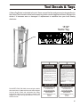
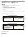
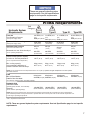
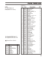
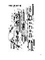
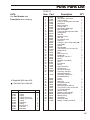
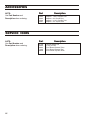
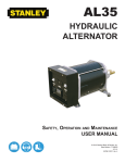
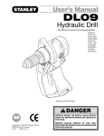
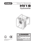
PD45
Post Driver
Remote ON/OFF Valve Model
Valve-In-Handle Model
Safety, and Operation
SERIOUS INJURY OR DEATH
COULD RESULT FROM THE
IMPROPER REPAIR OR
SERVICE OF THIS TOOL.
User’s Manual
REPAIRS AND/OR SERVICE TO
THIS TOOL MUST ONLY BE
DONE BY AN AUTHORIZED AND
CERTIFIED DEALER.
Read
The
Manual
Wear
Wear
Hearing
Breathing
Protection Protection
Wear
Eye
Protection
STANLEY
Stanley Hydraulic Tools
Copyright c 2001 The Stanley Works
OPS USA
59010 01/03 Ver. 2
3810 SE Naef Road
Milwaukie, OR 97267-5698 USA
Phone: (503) 659-5660
Fax: (503) 652-1780
Table of Contents
PD45
Post Driver
SERVICING THE
PD45 Post Driver:
This manual contains Safety,
Operation, and Troubleshooting
information. Stanley Hydraulic Tools
recommends that servicing of
hydraulic tools, other than routine
maintenance, must be performed
by an authorized and certified
dealer. Please read the DANGER
warning on the cover and the
SAFETY warning below.
Specifications
2
Safety Symbols
3
General Safety Instructions
4
Tool Decals and Tags
5
Hydraulic Hose Requirements
6
HTMA Requirements
7
Operating Instructions
8
Troubleshooting
Maintenance
Copyright c 2001 The Stanley Works
All rights reserved.
Under copyright law, this document may
not be copied in whole or in part without
the prior written consent of The Stanley
Works. This exception does not permit
copies to be made for others, whether or
not sold. Under the law, copying includes
translating into another language, format
or medium. This copyright notice must
appear on any permitted copies.
1
9-10
11
Parts Illustration
12 & 13
Parts List
14 & 15
Accessories
16
Warranty
17
SAFETY FIRST
It is the responsibility of the operator and
service technician to read rules and
instructions for safe and proper operation
and maintenance.
A cautious worker using common sense is
the greatest safety device.
Specifications
Weight (Standard)_____________65 lbs / 29.5 kg
Weight (Extended anvil)__________71 lbs / 32 kg.
Pressure Range_____________2000 psi / 140 bar
Flow Range______________7-9 gpm / 26-34 lmp
Optimum Flow_________________8 gpm / 30 lpm
Couplers_________________ HTMA Flush Face
Per NFPA T3.20.15/ISO 16028
Connect Size_________________3/8 female pipe
Length________________________30 in. / 76 cm
Width (Across Handles)_______10-1/8 in./25.7 cm
System Type___________________open
center
Port Size_____________________SAE 8 O-Ring
Hose Whips___________________________Yes
Capacity______________________#2, #3 and #4 lb/ft.
"U" Channel Sign Post
_______________#3 and #4 Strong Back (Heavy Duty)
"U" Channel Sign Post
_____________________________#1 Delineator Post
___________________2-1/2 in. / 63.5 mm Square Post
_____________________2-5/8 in. / 67 mm Round Post
30Lpm at 138bar
BHTMA CATEGORY
HTMA Class II _________7-9 gpm @ 2000 psi
NOTE
Weights, dimensions and operating specifications listed are subject to change
without notice. Where specifications are critical to your application, please
consult the factory.
2
SAFETY SYMBOLS
Safety symbols and signal words, as shown below, are used to emphasize all operator, maintenance
and repair actions which, if not strictly followed, could result in a life-threatening situation, bodily injury
or damage to equipment.
This is the safety alert symbol. It is used to alert you to potential personal
injury hazards. Obey all safety messages that follow this symbol to avoid
possible injury or death.
This safety alert and signal word indicate an imminently hazardous
situation which, if not avoided, will result in death or serious injury.
This safety alert and signal word indicate a potentially hazardous
situation which, if not avoided, could result in death or serious injury.
This safety alert and signal word indicate a potentially hazardous situation
which, if not avoided, may result in minor or moderate injury.
This signal word indicates a potentially hazardous situation which, if not
avoided, may result in property damage.
This signal word indicates a situation which, if not avoided, will result in
damage to the equipment.
This signal word indicates a situation which, if not avoided, may result in
damage to the equipment.
Always observe safety symbols. They are included for your safety and for the protection of the tool.
SOME HYDRAULIC FLUIDS ARE FLAMMABLE, NEVER ALLOW THESE
HYDRAULIC FLUIDS TO COME IN CONTACT WITH AN OPEN FLAME.
IF A HOSE WERE TO BURST OR IF A TOOL LEAK OCCURS NEXT TO
AN OPEN FLAME, THESE HYDRAULIC FLUIDS WILL IGNITE AND
COULD RESULT IN SERIOUS INJURY OR DEATH.
LOCAL SAFETY REGULATIONS
Enter any local safety regulations here. Keep these instructions in an area accessible
to the operator and maintenance personnel.
3
General Safety Instructions
Tool operators and maintenance personnel must always comply with the safety precautions
given in this manual and on the stickers and tags attached to the tool and hose.
These safety precautions are given for your safety. Review them carefully before operating
the tool and before performing general maintenance or repairs.
Supervising personnel should develop additional precautions relating to the specific work
area and local safety regulations. If so, place the added precautions in the space provided
on page 5.
This tool will provide safe and dependable service if operated in accordance with the instructions
given in this manual. Read and understand this manual and any stickers and tags attached to the
tool and hoses before operation. Failure to do so could result in personal injury or equipment
damage.
4
A
Operator must start in a work area without bystanders. The operator must be familiar with all prohibited work
areas such as excessive slopes and dangerous terrain conditions.
A
Establish a training program for all operators to ensure safe operations.
A
Do not operate the tool unless thoroughly trained or under the supervision of an instructor.
A
Always wear safety equipment such as goggles, head protection, and safety shoes at all times when operating
the tool.
A
Do not inspect or clean the tool while the hydraulic power source is connected. Accidental engagement of the
tool can cause serious injury.
A
Do not operate this tool without first reading the Operating Instructions.
A
Do not install or remove this tool while the hydraulic power source is connected. Accidental engagement of
the tool can cause serious injury.
A
Never operate the tool if you cannot be sure that underground utilities are not present. Underground electrical
utilities present an electrocution hazard. Underground gas utilities present an explosion hazard. Other
underground utilities may present other hazards.
A
Do not wear loose fitting clothing when operating the tool. Loose fitting clothing can get entangled with the
tool and cause serious injury.
A
Supply hoses must have a minimum working pressure rating of 2500 psi/175 bar.
A
Be sure all hose connections are tight.
A
The hydraulic circuit control valve must be in the “OFF” position when coupling or uncoupling the tool. Wipe
all couplers clean before connecting. Failure to do so may result in damage to the quick couplers and cause
overheating. Use only lint-free cloths.
A
Do not operate the tool at oil temperatures above 140° F/60° C. Operation at higher oil temperatures can
cause operator discomfort and may cause damage to the tool.
A
Do not operate a damaged, improperly adjusted, or incompletely assembled tool.
A
To avoid personal injury or equipment damage, all tool repair, maintenance and service must only be
performed by authorized and properly trained personnel.
A
Do not exceed the rated limits of the tool or use the tool for applications beyond its design capacity.
A
Always keep critical tool markings, such as labels and warning stickers legible.
A
Always replace parts with replacement parts recommended by Stanley Hydraulic Tools.
A
Check fastener tightness often and before each use daily.
Tool Decals & Tags
A Name Tag Sticker is attached to the tool. Never exceed the flow and pressure levels specified on
this sticker.The information listed on the name tag sticker must be legible at all times. Replace this
sticker if it becomes worn or damaged. A replacement is available from your local Stanley
distributor.
15197
Name Tag
DANGER
DANGER
1. FAILURE TO USE HYDRAULIC HOSE LABELED AND
CERTI-FIED AS NON-CONDUCTIVE WHEN USING
HYDRAULIC TOOLS ON OR NEAR ELECTRICAL LINES
MAY RESULT IN DEATH OR SERIOUS INJURY.
BEFORE USING HOSE LABELED AND CERTIFIED AS
NON- CONDUCTIVE ON OR NEAR ELECTRIC LINES.
BE SURE THE HOSE IS MAINTAINED AS NON- CONDUC TIVE . THE
HOSE SHOULD BE REGULARLY TESTED FOR ELECTRIC CURRENT
LEAKAGE IN ACCORDANCE WITH YOUR SAFETY DEPARTMENT
INSTRUCTIONS.
2. A HYDRAULIC LEAK OR BURST MAY CAUSE OIL
INJECTION INTO THE BODY OR CAUSE OTHER SEVERE PERSONAL
INJURY.
A.DO NOT EXCEED SPECIFIED FLOW AND
PRESSURE FOR THIS TOOL. EXCESS FLOW OR
PRESSURE MAY CAUSE A LEAK OR BURST.
B. DO NOT EXCEED RATED WORKING PRESSURE
OF HYDRAULIC HOSE USED WITH THIS TOOL.
EXCESS PRESSURE MAY CAUSE A LEAK OR
BURST.
C. C H E C K T O O L , H O S E , C O U P L E R S &
C O N N E C T O R S
D A I L Y
F O R
LEAKS. DO NOT FEEL FOR LEAKS WITH
YOUR HANDS. CONTACT WITH A LEAK MAY
RESULT IN SEVERE PERSONAL INJURY.
The SAFETY TAG, P/N 15875, shown at right, smaller
than actual size, is attached to the tool when shipped
from the factory. Read and understand the safety
instructions listed on this tag before removal. We
suggest you retain this tag and attach it to the tool
when not in use.
D. DO NOT LIFT OR CARRY TOOL BY THE HOSES. DO NOT ABUSE
HOSE. DO NOT USE KINKED, TORN OR DAMAGED HOSES.
3. MAKE SURE HYDRAULIC HOSES ARE PROPERLY
CONN-ECTED TO THE TOOL BEFORE PRESSURIZING
SYSTEM. SYSTEM PRESSURE HOSE MUST ALWAYS
BE CONNECTED TO TOOL “IN” PORT. SYSTEM
RETURN HOSE MUST ALWAYS BE CONNECTED AT
TOOL “OUT” PORT. REVERSING CONNECTIONS MAY
CAUSE REVERSE TOOL OPERATION WHICH CAN
CAUSE SEVERE PERSONAL INJURY.
4. DO NOT CONNECT CLOSED-CENTER TOOLS TO
OPEN-CENTER HYDRAULIC SYSTEMS. THIS MAY
CAUSE EXTREME SYSTEM HEAT AND/OR SEVERE
PERSONAL INJURY.
DO NOT CONNECT OPEN-CENTER TOOLS TO CLO SE D- CE NT ER
HYDRAULIC SYSTEMS. THIS MAY RESULT IN LOSS OF OTHER
HYDRAULIC FUNCTIONS POWERED BY THE SAME SYSTEM AND/OR
SEVERE PERSONAL INJURY.
5. BYSTANDERS MAY BE INJURED IN YOUR WORK
AREA. KEEP BYSTANDERS CLEAR OF YOUR WORK
AREA.
6. WEAR HEARING, EYE, FOOT, HAND AND HEAD PROTECTION.
7. TO AVOID PERSONAL INJURY OR EQUIPMENT DAMAGE, ALL TOOL
REPAIR, MAINTENANCE AND
SERVICE MUST BE
PERFORMED BY AUTHORIZED
AN D PR OP ER LY
TRAINED PERSONNEL.
IMPORTANT
IMPORTANT
READ OPERATION MANUAL AND
SAFETY INSTRUCTIONS FOR THIS
TOOL BEFORE USING IT.
READ OPERATION MANUAL AND
SAFETY INSTRUCTIONS FOR THIS
TOOL BEFORE USING IT.
USE ONLY PARTS AND REPAIR
PROCEDURES APPROVED BY
STANLEY AND DESCRIBED IN THE
OPERATION MANUAL.
USE ONLY PARTS AND REPAIR
PROCEDURES APPROVED BY
STANLEY AND DESCRIBED IN THE
OPERATION MANUAL.
TAG TO BE REMOVED ONLY BY TOOL
OPERATOR.
(517)
SEE OTHER SIDE
15875
TAG TO BE REMOVED ONLY BY TOOL
OPERATOR.
(517)
SEE OTHER SIDE
15875
5
Hydraulic Hose Requirements
HOSE TYPES
Hydraulic hose types authorized for use with Stanley Hydraulic Tools are as follows:
Certified non-conductive
Wire-braided (conductive)
Fabric-braided (not certified or labeled non-conductive)
Hose listed above is the only hose authorized for use near electrical conductors.
Hoses and listed above are conductive and must never be near electrical conductors.
HOSE SAFETY TAGS
To help ensure your safety, the following DANGER tags are attached to all hoses purchased from Stanley
Hydraulic Tools. DO NOT REMOVE THESE TAGS.
If the information in a tag is illegible because of wear or damage, replace the tag immediately. A new tag
may be obtained at no charge from your Stanley Distributor.
This Tag attached to “Certified Non-Conductive” hose.
DANGER
1. FAILURE TO USE HYDRAULIC HOSE LABELED AND CERTIFIED AS NON-CONDUCTIVE WHEN USING
HYDRAULIC TOOLS ON OR NEAR ELECTRIC LINES MAY RESULT IN DEATH OR SERIOUS INJURY.
FOR PROPER AND SAFE OPERATION, MAKE SURE THAT YOU HAVE BEEN PROPERLY TRAINED IN
CORRECT PROCEDURES REQUIRED FOR WORK ON OR AROUND ELECTRIC LINES.
2. BEFORE USING HYDRAULIC HOSE LABELED AND CERTIFIED AS NON-CONDUCTIVE ON OR NEAR
ELECTRIC LINES, WIPE THE ENTIRE LENGTH OF THE HOSE AND FITTINGS WITH A CLEAN,
DRY, ABSORBENT CLOTH TO REMOVE DIRT AND MOISTURE AND TEST HOSE FOR MAXIMUM
ALLOWABLE CURRENT LEAKAGE IN ACCORDANCE WITH SAFETY DEPARTMENT INSTRUCTIONS.
DANGER
4. HANDLE AND ROUTE HOSE CAREFULLY TO AVOID KINKING, ABRASION, CUTTING OR CONTACT
WITH HIGH TEMPERATURE SURFACES. DO NOT USE IF KINKED. DO NOT USE HOSE TO PULL OR
LIFT TOOLS, POWER UNITS, ETC.
5. CHECK ENTIRE HOSE FOR CUTS, CRACKS, LEAKS, ABRASIONS, BULGES OR DAMAGE TO
COUPLINGS. IF ANY OF THESE CONDITIONS EXIST, REPLACE THE HOSE IMMEDIATELY.
NEVER USE TAPE OR ANY DEVICE TO ATTEMPT TO MEND THE HOSE.
6.
AFTER EACH USE, STORE IN A CLEAN, DRY AREA.
3. DO NOT EXCEED HOSE WORKING PRESSURE OR ABUSE HOSE. IMPROPER USE OR HANDLING OF
HOSE COULD RESULT IN BURST OR OTHER HOSE FAILURE. KEEP HOSE AS FAR AWAY AS
POSSIBLE FROM BODY AND DO NOT PERMIT DIRECT CONTACT DURING USE. CONTACT AT THE
BURST CAN CAUSE BODILY INJECTION AND SEVERE PERSONAL INJURY.
SEE OTHER SIDE
SEE OTHER SIDE
Side 1
Side 2
DO NOT REMOVE THIS TAG
DO NOT REMOVE THIS TAG
(shown smaller than actual size) p/n 27987
This Tag attached to “Conductive” hose.
DANGER
DANGER
1. DO NOT USE THIS HYDRAULIC HOSE ON OR NEAR ELECTRIC LINES. THIS HOSE IS NOT
LABELED OR CERTIFIED AS NON-CONDUCTIVE. USING THIS HOSE ON OR NEAR ELECTRIC LINES
MAY RESULT IN DEATH OR SERIOUS INJURY.
5. CHECK ENTIRE HOSE FOR CUTS, CRACKS, LEAKS, ABRASIONS, BULGES OR DAMAGE TO
COUPLINGS. IF ANY OF THESE CONDITIONS EXIST, REPLACE THE HOSE IMMEDIATELY.
NEVER USE TAPE OR ANY DEVICE TO ATTEMPT TO MEND THE HOSE.
2. FOR PROPER AND SAFE OPERATION, MAKE SURE THAT YOU HAVE BEEN PROPERLY TRAINED IN
CORRECT PROCEDURES REQUIRED FOR WORK ON OR AROUND ELECTRIC LINES.
6.
AFTER EACH USE, STORE IN A CLEAN, DRY AREA.
3. DO NOT EXCEED HOSE WORKING PRESSURE OR ABUSE HOSE. IMPROPER USE OR HANDLING OF
HOSE COULD RESULT IN BURST OR OTHER HOSE FAILURE. KEEP HOSE AS FAR AWAY AS
POSSIBLE FROM BODY AND DO NOT PERMIT CONTACT DURING USE. CONTACT AT THE
BURST CAN CAUSE BODILY INJECTION AND SEVERE PERSONAL INJURY.
4. HANDLE AND ROUTE HOSE CAREFULLY TO AVOID KINKING, ABRASION, CUTTING OR CONTACT
WITH HIGH TEMPERATURE SURFACES. DO NOT USE IF KINKED. DO NOT USE HOSE TO PULL OR
LIFT TOOLS, POWER UNITS, ETC.
SEE OTHER SIDE
SEE OTHER SIDE
Side 1
Side 2
DO NOT REMOVE THIS TAG
DO NOT REMOVE THIS TAG
(shown smaller than actual size) p/n 29144
HOSE PRESSURE RATING
The rated working pressure of the hydraulic hose must be equal to or higher than the relief valve setting on
the hydraulic system.
6
These are general hydraulic system
requirements. See tool specifications
page for tool specific requirements.
HTMA Requirements
Hydraulic System
Requirements
Tool
Category:
20Lpm at 138bar
BHTMA CATEGORY
30Lpm at 138bar
BHTMA CATEGORY
Type I
Type RR
Type III
Type II
Flow rate
Tool Operating Pressure
4-6 GPM (15-23
7-9 GPM (26-34
11-13 GPM
lpm)
Lpm)
lpm)
(at the power supply outlet)
2000 psi (138 bar) 2000 psi (138 bar) 2000 psi (138 bar)
2000 psi (138 bar)
System relief valve setting
2100-2250
2100-2250
2100-2250
2200-2300
(145-155 bar)
(145-155 bar)
(145-155 bar)
(152-159 bar)
250 psi
250 psi
250 psi
250 psi
(17 bar)
(17 bar)
(17 bar)
(17 bar)
400 SSU
400 SSU
400 SSU
400 SSU
(82 centistokes)
(82 centistokes)
(82 centistokes)
(82 centistokes)
140° F (60° C)
140° F (60° C)
140° F (60° C)
140° F (60° C)
3 hp (2.24 kW)
40° F (22° C)
5 hp (3.73 kW)
40° F (22° C)
7 hp (5.22 kW)
40° F (22° C)
6 hp (4.5 kW)
40° F (22° C)
(at the power supply outlet)
Maximum back pressure
(at tool end of the return hose)
Measured at a max. fluid viscosity of:
(at min. operating temperature)
Temperature
Sufficient heat rejection capacity
to limit max. fluid temperature to:
(42-49
9-10.5 GPM
(34-40
lpm)
(at max. expected ambient temperature)
Min. cooling capacity
at a temperature difference of
between ambient and fluid temps
NOTE: Do not operate the tool at oil temperatures above 140 ° F (60° C). Operation at higher temperatures can cause operator
discomfort at the tool.
Filter
Min. full-flow filtration
sized for flow of at least:
25 microns
25 microns
25 microns
30 GPM (114 lpm)
30
GPM
(114
lpm)
30 GPM (114 lpm)
25 microns
30 GPM (114 lpm)
(For cold temp. startup and max. dirt-holding capacity)
Hydraulic fluid
Petroleum based
(premium grade, anti-wear, non-conductive)
Viscosity
(at min. and max. operating temps)
100-400 SSU*
100-400 SSU*
100-400 SSU*
100-400 SSU*
(20-82 centistokes)
(20-82 centistokes)
(20-82 centistokes)
(20-82 centistokes)
NOTE: When choosing hydraulic fluid, the expected oil temperature extremes that will be experienced in service determine the
most suitable temperature viscosity characteristics. Hydraulic fluids with a viscosity index over 140 will meet the requirements over
a wide range of operating temperatures.
*SSU = Saybolt Seconds Universal
NOTE: These are general hydraulic system requirements. See tool Specification page for tool specific
requirements.
7
Operating Instructions
Pre-Operation Procedures
Check the power source
1. Using a calibrated flowmeter and pressure
guage, check that the hydraulic power source
develops a flow of 7-9 gpm/26-34 lpm at 2000
psi/140 bar.
2. Make certain the hydraulic power source is
equipped with a relief valve set to open at
2100-2250 psi/140 bar.
Installing Adapters
1. The post hammer is designed to drive No. 1
thought No. 4 sign post, 2-1/2 inch square and
up to 2-5/8 inch diameter round post without
requiring adapters. If you are driving one of
these types of post, orient the post into the
tightest fit in the post driver foot.
Note: If uncoupled hoses are left in the
sun. pressure increase inside the hoses
may make them difficult to connect. When
possible, connect the free ends of the
operating hoses together.
Tool Operation
1. Observe all safety precautions.
2. Install the appropriate adapter as required.
3. Place the post driver foot firmly on the surface
to be driven.
4. Press the lever assembly on handle to start the
post driver.
Note: On Remote ON/OFF Valve Models
Place the post driver on/off control valve in
The “ON” position to start the post driver.
2. If you are driving smaller square or round
post, insert the adapter to the post driver foot
using two ½-hex head capscrews.
Note: Adequate down pressure is very
important.
Connecting Hoses
5. When the post is fully set in the ground,
release the lever assembly on handle.
1. Wipe all hose couplers with a clean, lint-free
cloth before making connections.
Cold Weather Operation
2. Connect the hoses from the hydraulic power
source to the tool fittings or quick disconnects.
It is a good practice to connect return hoses
first and disconnect them last to minimize or
avoid trapped pressure within the tool.
If the post hammer is to be used during cold
weather, preheat the hydraulic fluid at low engine
speed. When using the normally recommended
fluid, fluid temperature should be at or above
50°F/10°C (400ssu/82 centistrokes) before use.
3. If hose couplers are used, observe the arrow
on the coupler to ensure that the flow is in the
proper direction. The female coupler on the
tool hose is the inlet (pressure) coupler.
Damage to the hydraulic system or post driver can
result from use with fluid that is too viscous or
thick.
4. Move the hydraulic power source on/off
control valve to the ON position to operate
the tool.
8
Troubleshooting
This section describes how to find and resolve problems users may experience. If a situation occurs that is
not covered, call your Stanley Customer Service representative for assistance.
WARNING
Inspecting the tool or installing parts with the hydraulic hoses connected can result in severe personal injury or equipment
damage.
To prevent accidental startup, disconnect the hydraulic power before beginning any inspection or installation task.
If symptoms of poor performance develop, the following chart can be used as a guide to correct the problem.
When diagnosing faults in operation of the tool, always check that the hydraulic power source is supplying
the correct hydraulic flow and pressure to the tool as listed in the table. Use a flowmeter known to be
accurate. Check the flow with the hydraulic oil temperature at least 80° F/27° C.
Symptom
Possible Cause
Tool does not run. Power unit not functioning.
Tool does not hit
effectively.
Solution
*Check power source for proper
flow and pressure (7-9 gpm / 26-34
lpm, 2000 psi / 140 bar).
Couplers or Hoses blocked.
Remove restriction.
Pressure and return line hoses
reversed at ports.
Be sure hoses are connected to
their proper ports.
Mechanical failure of piston or
automatic valve.
Disassemble post driver and
inspect for damaged parts.
Power unit not functioning.
*Check power unit for proper flow
and pressure (7-9 gpm / 26-34 lpm,
2000 psi / 140 bar).
Remove restriction.
Couplers or hoses blocked.
Low accumulator charge (pressure Recharge accumulator. Replace
hose will pulse more than normal). diaphragm if charge loss continues.
Fluid too hot (above 140°F / 60°C)
Provide cooler to maintain proper
oil temperature (130°F / 55°C
maximum).
The anvil is not sliding freely in the
post driver foot.
Remove, clean, lubricate and
replace anvil as required.
continued
* Refer to Page 7, Hydraulic Power Source Check
9
Troubleshooting
Symptom
Tool operates
slow.
Tool gets hot.
Possible Cause
Solution
Low gpm supply from power unit
*Check power source for proper
flow (7-9 gpm / 26-64 lpm).
High backpressure.
Check hydraulic system for
excessive backpressure (over 250
psi / 17 bar).
Couplers or hoses blocked.
Remove restriction.
Orifice blocked.
Remove restriction.
Fluid too hot (above 140°F / 60°C)
or too cold (below 60°F / 16°C).
Check power source for proper
fluid temperature. Bypass cooler
to warm fluid up or provide cooler
to maintain proper temperature.
Relief valve set too low.
Adjust relief valve to 2100-2250
psi / 145-155 bar.
The anvil is not sliding freely in
the post driver foot.
Remove, clean, lubricate and
replace as required.
Hot fluid going through tool.
Check power unit. Be sure flow
rate is not too high causing part of
the fluid to go through the relief
valve. Provide cooler to maintain
proper fluid temperature (140°F /
60°C max).
Check relief valve setting.
Eliminate flow control devices.
Oil Leakage on
post.
Lower piston seal failure.
* Refer to Page 7, Hydraulic Power Source Check.
10
Replace seal.
Maintenance
Charging the Accumulator
If pressure is low, charge the accumulator as
described in the following section.
Accumulator Testing Procedure
F. Install the charging valve cap (or plug).
To check or charge the accumulator the following
equipment is required:
Accumulator Charging Procedure
!
Accumulator tester (Part Number 02835).
A. Perform steps A through D of the accumulator
testing procedure above.
!
Charging kit assembly (Part Number 31254)
(includes a regulator, hose and fittings).
!
NITROGEN bottle with an 800 psi/56 bar
minimum charge.
B. Connect the chuck of the charging assembly to
the charging valve on the accumulator tester or, if
preferred, remove the tester from the tool charging
valve and connect the charging assembly chuck
directly to the tool charging valve.
A. Remove the charging valve plug from the post
driver.
C. Adjust the regulator to the charging pressure of
600 psi/42 bar.
B. Holding the chuck end of Stanley tester (Part
Number 02835), turn the gauge fully counterclockwise to ensure the stem inside the chuck is
completely retracted.
Note: It may be necessary to set the
regulator at 650 to 700 psi/45-48 bar to
overcome any pressure drop through the
charging system.
C. Thread the tester onto the charging valve of the
tool accumulator, (Do not advance the guage-end
into the chuck end. Turn as a unit.) Seat the chuck
on the accumulator charging valve and hand
tighten only.
D. Advance the valve stem by turning the guage-end
clockwise until pressure is read on the guage
(charging pressure should be 500-700 psi/
34-38 bar).
E. If pressure is OK unscrew the gauge-end from the
chuck to retract the stem, then unscrew the entire
tester assembly from the tool accumulator
charging valve.
D. Open the valve on the charging assembly hose.
E. When the accumulator is fully charged close
the valve on the charging assembly hose and
remove the charging assembly chuck from the
accumulator tester of tool charging valve.
F. If the accumulator tester has been used, be sure
to turn the gauge-end fully counterclockwise
before removing the tester from the charging
valve of the tool.
G. Replace the o-ring plug.
Guage
Chuck
Tester
Charging
Valve
Accumulator Tester (P/N 02835)
Location Of Charging Valve
11
12
8
7
10
7
6
9
55
4
5
11
4
44
12
3
47
A
2
46
1
19 20
17 18
21
23
48
22
45
49
39
41
16
13 14
15
43
24
42
B
50
39
25
51
40
38
45
37
27
26
58
28
29
57
52
28
27
30
56
54
36
16
53
35
15
34
10
33
32
31
PD45 Parts Illustration
PD45132
PD45 Parts List
PD45132
Item Part
NOTE:
Use Part Number and
Description when ordering.
A- Supplied With Item # 1
B- Supplied With Item # 24
Denotes Part in Seal Kit
04595
Seal Kit
00293
01362
01604
01605
02022
04056
04379
04381
04386
04387
O-Ring
O-Ring
O-Ring (For item 1)
O-Ring (For item 24)
O-Ring
Rod Wiper
O-Ring
Backup Ring
Cup Seal
Rod Wiper
1
1
1
2
1
1
2
2
1
1
1
2
3
4
5
6
7
8
9
10
11
12
13
14
15
16
17
18
19
20
21
22
23
24
25
26
27
28
29
30
31
32
33
34
35
36
37
38
39
40
41
42
43
44
45
46
47
48
49
50
51
52
53
54
55
56
57
58
07493
20499
20387
12100
00899
20386
04374
20390
20384
370351
20385
02003
20398
08016
12139
08087
00293
04056
01362
04057
04077
04058
07479
350000
15195
15196
04381
04379
04378
07481
15191
04387
04780
04386
02022
04383
07485
04605
02900
04382
04571
07480
11588
20396
20392
00038
20399
12143
15183
12146
15189
15182
15194
15170
20388
48962
24059
24058
Description
O-Ring Plug-Male
Charge Valve
Plunger
Steel Ball 3/8 Dia. G
HHCS 1/4-20 UNC x ½ G
Cover Plate
Lock Nut 5/8-18
Lift Strap
Spacer
HHCS 5/8-11 UNC x 1-3/4
Pilot Ring
O-Ring 2-013 R16
Support Washer 3/4 Tr
Retaining Ring-3/4 Ex
Side Rod
Side Rod
O-Ring 2-115 R17£
Rod Wiper 5/16 x 9/16£
O-Ring 2-011 R16£
Bushing
Valve Spool OC
Spring
Accumulator Diaphragm
Straight Thread 45 EL
Hose Assy-15 in.
Hose Assy-14 in.
Back-Up Ring£
O-Ring 2-145 R17£
Porting Block
Piston
Adaptor Block
Rod Wiper£
Back up Washer
Cup Seal
O-Ring 2-228 R16£
Flow Sleeve Tube
Flow Sleeve
Push Pin
Roll Pin
Automatic Valve
Push Pin
Automatic Valve Body
Accumulator Valve Block
Valve Top Plate
Trigger Assy
Nut 1/4-20 Plain
Oval Pt. Set Screw 1/4
Upper Anvil Stop
Anvil Bushing
Spring
Anvil
Handle Bar
Set Screw
Post Driver Foot
Valve Actuator Housing
Decal, Name Tag LPH30
Male Coupler
Female Coupler
QTY
1
1
1
4
2
1
4
1
1
4
1
1
1
1
2
2
1
1
1
1
1
1
1
2
1
1
2
2
1
1
1
1
1
1
1
1
1
4
2
1
2
1
1
1
1
1
1
1
1
1
1
2
2
1
1
1
1
1
13
14
PD45 Parts List
PD45131
Item Part
NOTE:
Use Part Number and
Description when ordering.
A-Supplied With Item # 34
Denotes Part in Seal Kit
04595
Seal Kit
00293
01362
01604
01605
02022
04056
04379
04381
04386
04387
O-Ring
O-Ring
O-Ring (For item 1)
O-Ring (For item 24)
O-Ring
Rod Wiper
O-Ring
Backup Ring
Cup Seal
Rod Wiper
1
1
1
2
1
1
2
2
1
1
1
2
3
4
5
6
7
8
9
10
11
12
13
14
15
16
17
18
19
20
21
22
23
24
25
26
27
28
29
30
31
32
33
34
35
15190
11588
04374
00293
15188
07493
20499
07479
04381
04379
04378
04571
04382
04605
04383
12139
02022
04386
04780
04387
370351
15191
15189
15170
15182
15194
04058
07480
07481
07485
12146
12143
15183
350000
15195
36
15196
37
38
39
40
41
42
43
44
45
46
47
48
49
50
51
00026
02900
15197
03044
19693
13568
13567
01003
10536
24058
24059
16070
38631
38629
11499
Description
Top Plate
Accumulator Valve Block
Locknut 5/8-18
O-ring 11/16x7/8x3/32-115-R17£
Valve Spool
Male O-ring Plug
Charge Valve
Accumulator Diaphragm
Back Up Ring£
O-ring 2-9/16x2-3/4x3/32-R17£
Porting Block
Push Pin
Automatic Valve
Push Pin
Flow Sleeve Tube
Side Rod
O-Ring 2-1/4x2-1/2x1/8-228,R16£
Cup Seal£
Washer
Rod Wiper£
Capscrew,5/8-11x1-3/4 Hex HD
Adapter Block
Anvil
Post Driver Foot
Handle Bar
Set Screw, 3/8-16 x ½
Spring
Automatic Valve Body
Piston
Flow Sleeve
Spring
Upper Anvil Stop
Anvil Bushing
45° Elbow, 8-V50X-S
Hose Assy, Aeroquip
#FG1055HHG0150
Hose Assy, Aeroquip #
FG1055HHG0140
O-ring
Roll Pin
Name Tag
Hex Nipple 3/8 NPT
Danger Sricker
Back Up Ring A5 568-015
O-ring,9/16x11/16x1/16-015 R24
On-Off Valve Button
Selector Screw
Female Coupler 3/8 NPT
Male Coupler 3/8 NPT
Retaining Ring
Valve Spool
Valve Body Assy
Adaptor ½ SAE to 3/8 NPTF
QTY
1
1
4
1
1
1
1
1
2
2
1
2
1
4
1
4
1
1
1
1
4
1
1
1
2
2
1
1
1
1
1
1
1
2
1
1
1
2
1
2
1
2
2
2
1
1
1
1
1
1
2
15
Accessories
NOTE:
Use Part Number and
Description when ordering.
Part
15184
15185
15186
15187
Description
Adapter - 1-3/4 in. Square Post
Adapter - 2 in. Round Pipe
Adapter - 2-1/4 in. Square Post
Adapter - 2 in. Square Post
Service Tools
NOTE:
Use Part Number and
Description when ordering.
16
Part
01120
04337
04910
15187
05640
Description
Tamper Sleeve Tool
O-ring Tool Kit
Flow Sleeve Removal Tube
Flow Sleeve Removal Tool
Accumulator Cylinder Puller
Warranty
Stanley Hydraulic Tools (hereinafter called “Stanley”), subject to the exceptions contained below, warrants new hydraulic tools for a period of one
year from the date of sale to the first retail purchaser, or for a period of 2 years from the shipping date from Stanley, whichever period expires first,
to be free of defects in material and/or workmanship at the time of delivery, and will, at its option, repair or replace any tool or part of a tool, or new
part, which is found upon examination by a Stanley authorized service outlet or by Stanley’s factory in Milwaukie, Oregon to be DEFECTIVE IN
MATERIAL AND/OR WORKMANSHIP.
EXCEPTIONS FROM WARRANTY
NEW PARTS: New parts which are obtained individually are warranted, subject to the exceptions herein, to be free of defects in material and/or
workmanship at the time of delivery and for a period of 6 months after the date of first usage. Seals and diaphragms are warranted to be free of
defects in material and/or workmanship at the time of delivery and for a period of 6 months after the date of first usage or 2 years after the date of
delivery, whichever period expires first. Warranty for new parts is limited to replacement of defective parts only. Labor is not covered.
FREIGHT COSTS: Freight costs to return parts to Stanley, if requested by Stanley for the purpose of evaluating a warranty claim for warranty
credit, are covered under this policy if the claimed part or parts are approved for warranty credit. Freight costs for any part or parts which are not
approved for warranty credit will be the responsibility of the individual.
SEALS & DIAPHRAGMS: Seals and diaphragms installed in new tools are warranted to be free of defects in material and/or workmanship for a
period of 6 months after the date of first usage, or for a period of 2 years from the shipping date from Stanley, whichever period expires first.
CUTTING ACCESSORIES: Cutting accessories such as breaker tool bits are warranted to be free of defects in material and or workmanship at
the time of delivery only.
ITEMS PRODUCED BY OTHER MANUFACTURERS: Components which are not manufactured by Stanley and are warranted by their respective
manufacturers.
a. Costs incurred to remove a Stanley manufactured component in order to service an item manufactured by other
manufacturers.
ALTERATIONS & MODIFICATIONS: Alterations or modifications to any tool or part. All obligations under this warranty shall be terminated if the
new tool or part is altered or modified in any way.
NORMAL WEAR: Any failure or performance deficiency attributable to normal wear and tear such as tool bushings, retaining pins, wear plates,
bumpers, retaining rings and plugs, rubber bushings, recoil springs, etc.
INCIDENTAL/CONSEQUENTIAL DAMAGES: To the fullest extent permitted by applicable law, in no event will STANLEY be liable for any
incidental, consequential or special damages and/or expenses.
FREIGHT DAMAGE: Damage caused by improper storage or freight handling.
LOSS TIME: Loss of operating time to the user while the tool(s) is out of service.
IMPROPER OPERATION: Any failure or performance deficiency attributable to a failure to follow the guidelines and/or procedures as outlined in
the tool’s operation and maintenance manual.
MAINTENANCE: Any failure or performance deficiency attributable to not maintaining the tool(s) in good operating condition as outlined in the
Operation and Maintenance Manual.
HYDRAULIC PRESSURE & FLOW, HEAT, TYPE OF FLUID: Any failure or performance deficiency attributable to excess hydraulic pressure,
excess hydraulic back-pressure, excess hydraulic flow, excessive heat, or incorrect hydraulic fluid.
REPAIRS OR ALTERATIONS: Any failure or performance deficiency attributable to repairs by anyone which in Stanley’s sole judgement caused
or contributed to the failure or deficiency.
MIS-APPLICATION: Any failure or performance deficiency attributable to mis-application. “Mis-application” is defined as usage of products for
which they were not originally intended or usage of products in such a matter which exposes them to abuse or accident, without first obtaining the
written consent of Stanley. PERMISSION TO APPLY ANY PRODUCT FOR WHICH IT WAS NOT ORIGINALLY INTENDED CAN ONLY BE OBTAINED
FROM STANLEY ENGINEERING.
WARRANTY REGISTRATION: STANLEY ASSUMES NO LIABILITY FOR WARRANTY CLAIMS SUBMITTED FOR WHICH NO TOOL REGISTRATION IS ON RECORD. In the event a warranty claim is submitted and no tool registration is on record, no warranty credit will be issued without first
receiving documentation which proves the sale of the tool or the tools’ first date of usage. The term “DOCUMENTATION” as used in this
paragraph is defined as a bill of sale, or letter of intent from the first retail customer. A WARRANTY REGISTRATION FORM THAT IS NOT ALSO ON
RECORD WITH STANLEY WILL NOT BE ACCEPTED AS “DOCUMENTATION”.
NO ADDITIONAL WARRANTIES OR REPRESENTATIONS
This limited warranty and the obligation of Stanley thereunder is in lieu of all other warranties, expressed or implied including merchantability or
17
For additional Sales & Service information, contact:
Stanley Hydraulic Tools
Division of the Stanley Works
3810 SE Naef Road
Milwaukie, OR 97267 USA
Tel: (503) 659-5660
Fax: (503) 652-1780