1
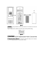
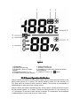
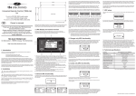
FT007 Wireless Indoor/Outdoor 8-Channel
Thermo-Hygrometer with Jumbo Display User Manual
1 Introduction
Thank you for your purchase of FT007 Wireless Indoor/Outdoor Thermo- Hygrometer with
Jumbo Display. The following user guide provides step by step instructions for installation and
operation.
2 Getting Started
Note: The power up sequence must be performed in the order shown in this section
(insert batteries in the remote transmitter(s) first, Display Console second).
The FT007 weather station consists of a display console (receiver), and a thermo-hygrometer
(remote transmitter).
2.1 Parts List
QTY
1
1
Item
Display Console
Frame Dimensions (LxHxW): 4.50 x 5.0 x 1.00 in
LCD Dimensions (LxW): 3.75 x 3.50”
LCD Segment Height: 1.25 inches
Thermo-hygrometer transmitter (FT007TH)
Dimensions (LxHxW): 4.5” x 2.0” x 0.75”
2.2 Recommend Tools
Hammer and nail for hanging remote thermo-hygrometer transmitter.2.3 Thermo-Hygrometer
Sensor Set Up
1. Remove the battery door on the back of the sensor by removing the set screw, as shown in
Figure 1 .
Figure 1
2. BEFORE inserting the batteries, locate the dip switches on the inside cover of the lid of
the transmitter.
Figure 2 displays all four switches in the OFF position (factory default setting).
Figure 2
3. Channel Number: The FT0054 supports up to eight transmitters. To set each channel
number (the default is Channel 1), change Dip Switches 1, 2 and 3, as referenced in Table
1.
4. Temperature Units of Measure: To change the transmitter display units of measure
(°F vs. °C), change Dip Switch 4, as referenced in Table 1.
1
DOWN
DOWN
DOWN
DOWN
UP
UP
UP
UP
-----
DIP SWITCH
2
3
DOWN
DOWN
DOWN
UP
UP
DOWN
UP
UP
DOWN
DOWN
DOWN
UP
UP
DOWN
UP
UP
--------Table 1
FUNCTION
4
----------------DOWN
UP
Channel 1
Channel 2
Channel 3
Channel 4
Channel 5
Channel 6
Channel 7
Channel 8
°F
°C
1. Insert two AAA batteries.
2. After inserting the batteries, the remote sensor LED indicator will light for 4 seconds,
and then flash once per 60 seconds thereafter. Each time it flashes, the sensor is
transmitting data.
3. Verify the correct channel number (CH) and temperature units of measure (°F vs. °C)
are on the display, as shown in Figure 3.
Figure 3
(1) temperature
(2) temperature units (°F vs. °C)
(3) channel number
(4) relative humidity
4. Close the battery door. Make sure the gasket (around the battery compartment) is
properly seated in its trace prior to closing the door. Tighten the set screw.
2.3 Display Console Set Up
1. Move the remote thermo-hygrometer(s) about 5 to 10’ away from the display console
(if the sensor is too close, it may not be received by the display console). If you have
more than one thermo-hygrometer, make sure they are all powered up and
transmitting on different channels.
2. Remove the battery door on the back of the display, as shown in Figure 4. Insert four
AAA (alkaline or lithium, avoid rechargeable) batteries in the back of the display
console.
Figure 4
All of the LCD segments will light up for a few seconds to verify all segments are operating
properly.
3. Replace the battery door, and fold out the desk stand and place the console in the
upright position.
The console will instantly display indoor temperature and humidity as designated by
the
icon. The remote temperature and humidity will update on the display within
a few minutes on the appropriate channel.
While in the search mode, the remote search icon
will be constantly displayed.
If you have more than once remote sensor (up to eight remotes are supported), the
display will automatically toggle between sensors until all sensors have reported in.
Do not touch any buttons until the remote sensor has reported in, or the radio search
icon
is no longer on, otherwise the remote sensor search mode will be
terminated. When the remote sensor temperature and humidity has been received,
the console will automatically switch to the normal mode, and all further settings can
be performed.
If the remote does not update, please reference the troubleshooting guide in Section 8.
2.3.1 Display Console Layout
Note: The following illustration shows the full segments of the LCD for description
purposes only and will not appear like this during normal operation.
Figure 5
1. Temperature
2. Min/Max Record mode
3. Temperature, Rate of Change
indicator
4. Temperature units (°F or °C)
5. Humidity, Rate of Change indicator
6. Relative Humidity (%)
7. Humidity Comfort Icon
8. Reception Icon (solid when searching, flashes
when updating)
9. Channel 1,2,3,4,5,6,7,8,
indictor
2.3.2 Sensor Operation Verification
Verify the indoor and outdoor humidity match closely with the console and sensor array in the
same location (about 5 to 10’ apart). The sensors should be within 10% (the accuracy is ±
5%). Allow about 30 minutes for both sensors to stabilize. The humidity can be adjusted or
calibrated later to match each other a known source.
Verify the indoor and outdoor temperature match closely with the console and sensor array in
the same location (about 5 to 10’ apart). The sensors should be within 2°C (the accuracy is ±
1°C). Allow about 30 minutes for both sensors to stabilize. The temperature can be adjusted
or calibrated later to match each other or a known source.
3 Remote Sensor Installation
It is recommended you mount the remote sensor on a north facing wall, in a shaded area.
Direct sunlight and radiant heat sources will result in inaccurate temperature readings.
Although the sensor is water resistant, it is best to mount in a well protected area, such as
under an eve. Use a screw or nail (not included) to affix the remote sensor to the wall, as
shown in Figure 6.
Figure 6
4 Display Features
4.1 Comfort Icon
The comfort icon is based on humidity ranges specified in Figure 7. The icon is displayed for
indoor humidity, remote channel 1 humidity and optional remote channels 2 through 8
humidity.
RH<45%
Dry
RH 45%~65%
Comfortable
Figure 7
RH >65%
Wet
4.2 Rate of Change Icon
The rate of change icon
detects rapid changes in temperature and humidity. If the
arrow points upward, the temperature is increasing at a rate of +2°C per 30 minutes (or
greater), or humidity is increasing at a rate of +5% per 30 minutes (or greater). If the arrow
points downward, the temperature is decreasing at a rate of -2°C per 30 minutes (or less), or
humidity is decreasing at a rate of -5% per 30 minutes (or less).
5 Console Operation
Note: The console has three buttons for easy operation: MIN/MAX/- button,
CLEAR/ADJUST button, and CHANNEL/+ button.
5.1 Min/Max Mode
The Min/Max mode displays the minimum and maximum temperature and humidity (since
reset of the unit) for the indoor, remote channel 1 through 8 sensors.
Prior to entering the MIN/MAX mode, press the CHANNEL/+ button to select the temperature
and humidity values you wish to view.
1. Display Maximum
Maximum. Press the MIN/MAX button once to display the maximum. The
MAX icon will be displayed.
2. Clear Maximum. To reset the maximum values to the current values, press and hold
the CLEAR button for 3 seconds.
3. Display Minimum
Minimum. Press the MIN/MAX button again to display the minimum. The
MIN icon will be displayed.
4. Clear Minimum. To reset the minimum values to the current values, press and hold
the CLEAR button for 3 seconds.
To return to normal mode, press the MIN/MAX button again.
5.2 Indoor/Outdoor Channel Selection
Press the CHANNEL/+ button to switch the display between the indoor temperature and
humidity
, remote sensors 1 through 8, and scroll mode
. In scroll mode, all of the
indoor and detected outdoor sensors will be displayed in five second intervals.
5.3 Temperature Units of Measure
The default temperature units of measure are degrees Fahrenheit. To toggle between
degrees Celsius and degrees Fahrenheit, press and hold the MIN/MAX button for 3 seconds.
5.4 Sensor Search Mode
If any of the sensor communication is lost, dashes (--.-) will be displayed on the screen. To
reacquire the signal:
1. If a specific channel is lost, press the CHANNEL/+ button to display this channel, then
Press and hold the CHANNEL/+ button for 3 seconds, and the remote search icon
will be constantly displayed for up to 10 minutes. Once the signal is reacquired,
the remote search icon
will turn off, and the current values will be displayed.
2. If new sensors are added, subtracted, or multiple sensor channels are lost, press the
CHANNEL/+ button until the indoor channel
is displayed. Press and hold the
CHANNEL/+ button for 3 seconds, and the remote search icon
will be
constantly displayed for up to 10 minutes. Once the signal is reacquired, the remote
search icon
will turn off, and the current values will be displayed.
5.5 Best Practices for Wireless Communication
Wireless communication is susceptible to interference, distance, walls and metal barriers. We
recommend the following best practices for trouble free wireless communication.
1. Electro-Magnetic Interference (EMI)
(EMI). Keep the console several feet away from
computer monitors and TVs.
2. Radio Frequency Interference (RFI). If you have other 433 MHz devices and
communication is intermittent, try turning off these other devices for troubleshooting
purposes. You may need to relocate the transmitters or receivers to avoid intermittent
communication.
3. Line of Sight Rating. This device is rated at 300 feet line of sight (no interference,
barriers or walls) but typically you will get 100 feet maximum under most real-world
installations, which include passing through barriers or walls.
4. Metal Barriers. Radio frequency will not pass through metal barriers such as
aluminum siding. If you have metal siding, align the remote and console through a
window to get a clear line of sight.
5.6 Adjustment or Calibration
5.6.1 Humidity Calibration
Prior to entering the calibration mode, press the CHANNEL/+ button to select the humidity
sensor you wish to adjust.
To enter the humidity calibration mode, press and hold the ADJUST and MIN/MAX buttons at
the same time for 5 seconds and the humidity value will begin flashing. Press the
CHANNEL/+ button to increase the humidity and the MIN/MAX/- button to decrease the
humidity reading in 1% increments. To rapidly increase (or decrease) the humidity reading,
press and hold the CHANNEL/+ or MIN/MAX/- button.
To return the humidity to the actual or uncalibrated measurement, press the ADJUST button.
Once the displayed humidity equals the calibrated source, press and hold the ADJUST button
for three seconds, or wait 15 seconds for timeout, and the humidity value will stop flashing.
6 Specifications
7.1 Wireless Specifications
•
•
•
Line of sight wireless transmission (in open air): 300 feet, 100 feet under most
conditions.
Frequency: 433 MHz
Update Rate: 60 seconds
7.2 Measurement Specifications
The following table provides specifications for the measured parameters.
Measurement
Indoor Temperature
Outdoor Temperature
Indoor Humidity
Range
0 to 60°C
-40 to 60°C
10 to 99 %
Outdoor Humidity
10 to 99%
Accuracy
± 1°C
± 1°C
± 5% (only
guaranteed between
20 to 90%)
± 5% (only
guaranteed between
20 to 90%)
Resolution
0.1°C
0.1°C
1%
1%
7.3 Power Consumption
•
•
•
Base station (display console) : 4 x AAA 1.5V Alkaline or Lithium batteries (not
included)
Remote sensor : 2 x AAA 1.5V Alkaline or Lithium batteries (not included)
Battery life: Minimum 12 months for base station with one sensor and excellent
reception. Intermittent reception and multiple sensors may reduce the battery life.
Minimum 12 months for thermometer-hygrometer sensor (use lithium batteries in cold
weather climates less than -20°C)