Transcript
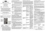
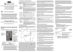
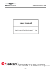
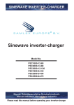
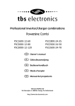
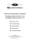
118mm
You can browse through the list of available parameters by turning the rotary controller
knob (3) clockwise or counter clockwise. When the ambient light conditions are poor, the
backlight button (4) can be pressed to activate the display backlight. Use the same button
to deactivate the backlight again.
When the desired AC In Current Limit level is selected, press the rotary controller knob (3)
once to jump back to the normal operating display mode. The MCC and AC In Current
Limit levels will be stored in internal memory and remains the setpoint until it is changed
again using this menu.
When the TBS device shuts down automatically caused by tripping an error mode, the
alarm LED (7) starts flashing and the display will show the corresponding error type.
This error message will automatically disappear again when the error has been solved.
In the top-right area of the display, you can see a small battery icon which represents the
charging state of the battery. This state is directly linked to the charge status bar on the
battery charger itself.
To turn off the TBS device or to put it into a different operating mode, you can press the
power button (6) once. This will show the inverter, charger or combi power options menu :
7. URC setup
When the rotary controller knob (3) is pressed for three seconds, the following screen will
appear :
58mm
Universal Remote Control (TBSLink)
for
61mm
113mm
cutout area
Powersine PS1000-1800 inverter series
Omnicharge OC20-60 charger series
Powersine Combi PSC1600-1800 combi series
mounting screw hole
Owner’s manual
EN
Thank you for purchasing the TBS Electronics
Universal Remote Control.
Please read this owner’s manual for information
about using the product correctly and safely.
Keep this owner’s manual close to the device for
future reference.
Please follow the installation instructions of your TBS device to connect the URC correctly.
The URC must be connected inside the connection compartment of a TBS inverter or
combi, while it can be connected externally (bottom panel) to a TBS battery charger.
The choice of operating mode on the URC will always override the position of the main
power switch on the inverter. You can also switch directly to TBS device standby mode in
the normal operating screen by pressing the power button (6) for three seconds. The TBS
device and URC can be activated again by pressing the power button (6) once.
3. URC Display and control overview
Now that the URC is connected to the TBS device, you can turn it on which will
automatically activate the remote panel as well. Before going into specific details, the
image below shows the display and control overview of the URC :
1
By turning the rotary controller you can select the “Remote Control Setup” option and
press the rotary controller once. The following screen with URC properties will appear :
Now you can select the property that you wish to change, by turning and pressing the
rotary controller accordingly. A screen will appear that allows you to change the property
value by turning rotary controller again. The image below shows the display contrast
property as an example :
Note : In standby or sleep mode, the device still draws a very small current from the battery in order to be
able to detect a power button press on the remote panel. When you are leaving the device off for
an extended amount of time, it is advised to turn off the device using the local main power switch.
This way the device will draw zero current from the batteries.
2
5. Charger only URC functionality
TBS ELECTRONICS BV
De Marowijne 3, 1689AR, Zwaag, The Netherlands
select
power
8
http://www.tbs-electronics.com
By turning the rotary controller knob you can choose your preferred option. This option can
be executed by pushing the rotary controller knob, or pressing the power button. Option
“Return” will escape from this screen and jumps to the normal operating screen again.
Changing to a different TBS device operating mode, will also change the mode indicator
(1) from I to II or vice versa. If an inverter was already running in ASB mode before
entering the power options menu, the “Switch to ASB mode” option is replaced by “Switch
to normal mode”. If a charger was already running in Forced float mode before entering
the power options menu, the “Switch to Forced float mode” option is replaced by “Switch to
normal mode”. If a combi was already running in Charger only mode before entering the
power options menu, the “Switch to Charger only” option is replaced by “Switch to normal
mode”.
3
alarm
7
When the URC is connected to a battery charger, it is possible to dynamically reduce the
Maximum Charging Current (MCC). This feature is ideal in situations where the user
wishes to temporarily reduce the chargers AC power consumption, for example when
limited AC source power is available. To activate the MCC menu, press the rotary
controller knob (3) once which will show the following screen :
enter/menu
The desired value can be stored by pressing the rotary controller for three seconds. This
way of saving a property value change, would result in jumping back to the normal
operating display mode again. When you wish to change more than one property, press
the rotary controller once and you will jump back to the URC properties list again were you
can select the next property to change. When all desired URC properties are changed,
select and press “Return” in the URC property list screen which will save all changed
values and jump back to the normal operating display mode. If no buttons are touched for
90 seconds when operating in a setup screen, the URC will automatically jump back to the
normal operating display again without saving any changed property values.
universal remote control
8. Technical specifications
1. Introduction
Thank you for purchasing the TBS Electronics Universal Remote Control (URC) for
controlling the following TBS devices :
- Powersine PS1000-1800 inverter series
- Omnicharge OC20-60 battery charger series
- Powersine Combi PSC1600-1800 inverter/charger combi series
The URC features an advanced graphical display and a smart user interface for easy
operation. Using the URC you can readout all available parameters of the connected TBS
device and remotely turn this product on and off. The communication between the URC
and the TBS device is made using the rugged industrial TBSLink protocol which supports
wirelengths of up to 50 meters. A TBSLink connection accepts simple CAT5 Ethernet
patch cables (straight wired).
To get optimal performance and safe operation from your URC and TBS device, it must be
installed and used properly. Please read this manual very carefully, especially the warning
and caution statements, before installing and using the URC.
2. Installation
!
CAUTION
WARNING
Never connect a TBSLink connector to other network types like ethernet, or to the
e-xpert series quick connection kit!
Before removing the connection compartment panel of your device, make sure to
disconnect the battery and unplug all AC sources first. Then leave the power switch
in position “I” for at least 10 seconds.
The URC must be mounted in a dry location where it is not exposed to direct sunlight. The
ambient air temperature of this location should be between -10°C and +50°C (humidity <
95% non condensing).
6
5
4
1. TBS device mode indicator. With an inverter connected, symbol I indicates inverter on
in normal mode. Symbol II indicates inverter on in ASB mode. With a charger
connected, symbol I indicates charger on in normal mode. Symbol II indicates charger
on in forced float mode. With a combi connected, symbol I indicates combi on in normal
mode. Symbol II indicates combi on in charger only mode.
2. TBS device type indicator. Automatically shows which inverter, charger or combi model
is connected to the URC.
3. Intelligent rotary controller knob. Three way control knob which can be used to select
values, browse through lists and change numeric values.
4. Backlight button. Activates or deactivates the backlight of the LCD
5. LCD parameter field. In normal operating conditions, this field indicates all available
parameters and it's corresponding values. When this list has more than four rows, you
can use the rotary controller to browse through this list.
6. Power button. This button activates the power options menu, or directly turns off the
TBS device when pressed for 3 seconds.
7. Alarm indicator LED. Flashes red when a TBS device error has occurred. The
corresponding error type will be showed on the display.
8. Power indicator LED. Lits green when the TBS device and remote panel are on.
Now it's possible to turn the rotary controller knob (3) clockwise or counter clockwise to
adjust to the preferred charge current level. The charge current level is represented as
percentage of maximum rated charge current, and in actual Amps (between brackets). The
minimum MCC level is 10%. When the desired MCC level is selected, press the rotary
controller knob (3) once to jump back to the normal operating display mode. The MCC
level will be stored in internal memory and remains the setpoint until it is changed again
using the MCC menu.
In the top-right area of the display, you can see a small battery icon which represents the
charging state of the battery. This state is directly linked to the charge status bar on the
battery charger itself.
6. Combi only URC functionality
When the URC is connected to a combi device, it is possible to dynamically reduce the
Maximum Charging Current (MCC) and set the AC input current limit level. Reducing the
MCC is ideal in situations where the user wishes to temporarily reduce the chargers AC
power consumption, for example when limited AC source power is available. To activate
the MCC menu, press the rotary controller knob (3) once which will show the following
screen :
Parameter
Databus type
Connection cable type
Nominal operating voltages
Universal Remote Control (TBSLink)
TBSLink point to point
UTP straight wired patch cable RJ45(8)-RJ45(8)
12VDC or 24VDC
Power consumption [BL on]
12mA [47mA]
Operating temperature range
-10C to +50 C
Storage temperature range
-20C to +65 C
Enclosure body size (lxhxw)
130 x 70 x 36 mm
Needed panel cutout (lxh)
113 x 61mm
Maximum mounting depth
30 mm
Protection class
Total weight
Housing material
IP30
140 grams
ABS
Note: the given specifications are subject to change without notice.
4. General URC functionality
As explained above, when the TBS device is switched on using it's main power switch, the
URC will start up as well showing a green power LED and the following startup screen for
a few seconds :
By turning the rotary controller knob (3), the preferred charge current can be set in
percentage of maximum rated charge current, or just in Amps.
When the rotary controller knob (3) is pressed once again, the AC In Current Limit level
screen appears :
Never put excessive pressing force on the display window area, since this could
permanently damage the display. For panel mounting the URC, the following
measurements must be taken into account :
This screen will be followed by the normal operating display mode where all available
parameters of the inverter, charger or combi will be showed :
By turning the rotary controller knob (3), the preferred AC input current limit level can be
set in Amps. When this input current level is exceeded, the combi immediately reduces the
charge current automatically in order to keep the AC input current below this predefined
level. When this input current level remains being exceeded, even when the charge
current has been reduced to zero, the Power Boost feature will be activated (see
Powersine Combi combi manual for further information).
URC Manual Rev3e / Printed in The Netherlands