1
Flow Meter | FC01- Ex
USER HANDBOOK
M_FC01-EX_0614_e
Flow Meter | FC01- Ex
Please follow these installation and adjustment instructions carefully.
Failure to comply with these instructions or misuse of this equipment will void your warranty coverage. The instructions cover software version 2.40.
Equipment installation, connection and adjustment by qualified personnel only.
Failure to comply, or misuse of this equipment, could result in serious damage both to the
equipment itself and to the installation. FlowVision is unable to accept responsibility for
customer or third party liability, warranty claims or damage caused by incorrect installation
or improper handling resulting form non-observance of these instructions.
Monitoring heads are not freely interchangeable with the FC01-Ex. The assembly of
mating parts must be maintained.
Electronic control unit and monitoring head are always packed and dispatched in
pairs.
2
FC01- Ex | Flow Meter
TABLE OF CONTENTS
Table of contents
1 Description . . . . . . . . . . . . . . . . . . . . . . . . . . . . . . . . . . . . . . . . . . . . . . . . . . . . . . 8
2 Ex atmosphere - Definitions and mounting instructions . . . . . . . . . . . . . . . . . . . 8
2.1 Information on explosion protection . . . . . . . . . . . . . . . . . . . . . . . . . . . . . . . . . . . . . . . . . . . . 8
2.2 Classification Zones . . . . . . . . . . . . . . . . . . . . . . . . . . . . . . . . . . . . . . . . . . . . . . . . . . . . . . . . . 9
2.2.1 Equipment group II, category 1 (Zones 0 and 20) . . . . . . . . . . . . . . . . . . . . . . . . . . . 9
2.2.2 Equipment group II, category 2 (Zones 1 and 21) . . . . . . . . . . . . . . . . . . . . . . . . . . . 9
2.2.3 Equipment group II, category 3 (Zones 2 and 22) . . . . . . . . . . . . . . . . . . . . . . . . . . . 9
2.3 Materials used for calorimetric monitoring heads . . . . . . . . . . . . . . . . . . . . . . . . . . . . . . . . . 10
2.3.1 Stainless steel 1.4571/AISI 316 Ti . . . . . . . . . . . . . . . . . . . . . . . . . . . . . . . . . . . . . . . 10
2.3.2 Nickel-based alloy Hastelloy C4/2.4610 . . . . . . . . . . . . . . . . . . . . . . . . . . . . . . . . . . 10
2.3.3 Titanium G7, 3.7235 . . . . . . . . . . . . . . . . . . . . . . . . . . . . . . . . . . . . . . . . . . . . . . . . . . 10
2.4 Temperature limits . . . . . . . . . . . . . . . . . . . . . . . . . . . . . . . . . . . . . . . . . . . . . . . . . . . . . . . . . 11
2.4.1 Gases . . . . . . . . . . . . . . . . . . . . . . . . . . . . . . . . . . . . . . . . . . . . . . . . . . . . . . . . . . . . 11
2.4.2 Dust . . . . . . . . . . . . . . . . . . . . . . . . . . . . . . . . . . . . . . . . . . . . . . . . . . . . . . . . . . . . . . 11
2.5 Cable length . . . . . . . . . . . . . . . . . . . . . . . . . . . . . . . . . . . . . . . . . . . . . . . . . . . . . . . . . . . . . . 11
2.6 Installation - Ex-components . . . . . . . . . . . . . . . . . . . . . . . . . . . . . . . . . . . . . . . . . . . . . . . . . 12
2.6.1 Installation - calorimetric monitoring head . . . . . . . . . . . . . . . . . . . . . . . . . . . . . . . . 12
2.6.1.1 Mechanical installation - thread-mounted monitoring head CST-Ex . . . . . 12
2.6.1.2 Mounting instructions . . . . . . . . . . . . . . . . . . . . . . . . . . . . . . . . . . . . . . . . 13
2.6.1.2.1 Liquid media . . . . . . . . . . . . . . . . . . . . . . . . . . . . . . . . . . . . . . 14
2.6.1.2.2 Gases . . . . . . . . . . . . . . . . . . . . . . . . . . . . . . . . . . . . . . . . . . . 15
2.6.1.2.3 Depth of threading . . . . . . . . . . . . . . . . . . . . . . . . . . . . . . . . . 15
2.6.1.2.4 Sealing . . . . . . . . . . . . . . . . . . . . . . . . . . . . . . . . . . . . . . . . . . 15
2.6.1.3 Electrical connection . . . . . . . . . . . . . . . . . . . . . . . . . . . . . . . . . . . . . . . . 16
2.6.2 Installation of electronic control unit FC01-Ex . . . . . . . . . . . . . . . . . . . . . . . . . . . . . 18
2.6.2.1 Mechanical installation . . . . . . . . . . . . . . . . . . . . . . . . . . . . . . . . . . . . . . . 18
2.6.2.2 Electrical connection . . . . . . . . . . . . . . . . . . . . . . . . . . . . . . . . . . . . . . . . . 18
2.6.2.2.1 Circuit diagram FC01-Ex . . . . . . . . . . . . . . . . . . . . . . . . . . . . 21
2.6.2.2.2 Electrical connection - frequency output
(version FC01-Ex-U1T4) . . . . . . . . . . . . . . . . . . . . . . . . . . . . 22
2.7 Maintenance . . . . . . . . . . . . . . . . . . . . . . . . . . . . . . . . . . . . . . . . . . . . . . . . . . . . . . . . . . . . . . 24
2.7.1 Monitoring head CST-Ex . . . . . . . . . . . . . . . . . . . . . . . . . . . . . . . . . . . . . . . . . . . . . . 24
2.7.2 Flow Meter FC01-Ex . . . . . . . . . . . . . . . . . . . . . . . . . . . . . . . . . . . . . . . . . . . . . . . . . . 24
3
Flow Meter | FC01- Ex
TABLE OF CONTENTS
3 Normal atmosphere - Definitions and mounting instructions . . . . . . . . . . . . . . . . . . . 25
3.1 Measuring procedure . . . . . . . . . . . . . . . . . . . . . . . . . . . . . . . . . . . . . . . . . . . . . . . . . . . . . . . 25
3.2 System description . . . . . . . . . . . . . . . . . . . . . . . . . . . . . . . . . . . . . . . . . . . . . . . . . . . . . . . . 26
3.2.1 User interfaces . . . . . . . . . . . . . . . . . . . . . . . . . . . . . . . . . . . . . . . . . . . . . . . . . . . . . . 27
3.3 Customer calibration . . . . . . . . . . . . . . . . . . . . . . . . . . . . . . . . . . . . . . . . . . . . . . . . . . . . . . . 29
3.3.1 Options and advantage of customer calibration . . . . . . . . . . . . . . . . . . . . . . . . . . . . 29
3.3.2 Special flow and installation conditions . . . . . . . . . . . . . . . . . . . . . . . . . . . . . . . . . . 29
3.3.3 How to achieve higher accuracy . . . . . . . . . . . . . . . . . . . . . . . . . . . . . . . . . . . . . . . . 30
3.3.4 How to achieve the full scale range . . . . . . . . . . . . . . . . . . . . . . . . . . . . . . . . . . . . . 30
3.3.5 Pin-point adjustment (selective accuracy) . . . . . . . . . . . . . . . . . . . . . . . . . . . . . . . . . 30
3.3.6. Reproduction of precise measuring instruments . . . . . . . . . . . . . . . . . . . . . . . . . . . 30
3.3.7 Use of standard monitoring heads . . . . . . . . . . . . . . . . . . . . . . . . . . . . . . . . . . . . . . 30
4 Technical implementation of customer calibration . . . . . . . . . . . . . . . . . . . . . . . 31
4.1 Calculation . . . . . . . . . . . . . . . . . . . . . . . . . . . . . . . . . . . . . . . . . . . . . . . . . . . . . . . . . . . . . . . 31
4.2 Calibration . . . . . . . . . . . . . . . . . . . . . . . . . . . . . . . . . . . . . . . . . . . . . . . . . . . . . . . . . . . . . . . 31
4.2.1 Selection of CTD value (temperature differential) . . . . . . . . . . . . . . . . . . . . . . . . . . . 31
4.2.2 Trim point selection - number and position . . . . . . . . . . . . . . . . . . . . . . . . . . . . . . . 34
4.2.3 MAX-MIN Calibration procedure . . . . . . . . . . . . . . . . . . . . . . . . . . . . . . . . . . . . . . . . 34
4.2.4 Zero point, directional discrimination and upper characteristic curve value . . . . . . 35
4.2.5 New curve / Old curve . . . . . . . . . . . . . . . . . . . . . . . . . . . . . . . . . . . . . . . . . . . . . . . 35
4.2.5.1 New curve . . . . . . . . . . . . . . . . . . . . . . . . . . . . . . . . . . . . . . . . . . . . . . . . . 35
4.2.5.2 Old curve . . . . . . . . . . . . . . . . . . . . . . . . . . . . . . . . . . . . . . . . . . . . . . . . . . 36
4.2.6 Transfer of C- and T values - Re-establishment of T value . . . . . . . . . . . . . . . . . . . . 36
4.2.6.1 Establishing the T value - general . . . . . . . . . . . . . . . . . . . . . . . . . . . . . . . 36
4.2.6.2 Establishing the new T value . . . . . . . . . . . . . . . . . . . . . . . . . . . . . . . . . . . 37
4.2.7 Expanding the characteristic curve . . . . . . . . . . . . . . . . . . . . . . . . . . . . . . . . . . . . . . 38
5 Operation . . . . . . . . . . . . . . . . . . . . . . . . . . . . . . . . . . . . . . . . . . . . . . . . . . . . . . . 39
5.1 Operating system . . . . . . . . . . . . . . . . . . . . . . . . . . . . . . . . . . . . . . . . . . . . . . . . . . . . . . . . . . 39
5.1.1 Configuration . . . . . . . . . . . . . . . . . . . . . . . . . . . . . . . . . . . . . . . . . . . . . . . . . . . . . . . 41
5.1.1.1 Selection of monitoring head (menu option: SENSOR SELECT) . . . . . . . 41
5.1.1.2 Monitoring head data (menu option: SENSOR CODE) . . . . . . . . . . . . . . . 41
5.1.1.3 Medium selection (menu option: MEDIUM SELECT) . . . . . . . . . . . . . . . . . 41
5.1.1.4 Custom designed calibration (menu option: CUSTOMER TRIM) . . . . . . . . 41
5.1.1.4.1 Access to menu option CUSTOMER TRIM . . . . . . . . . . . . . . . 41
5.1.1.4.2 Old curve / New curve . . . . . . . . . . . . . . . . . . . . . . . . . . . . . . 42
5.1.1.4.3 Number of trim points . . . . . . . . . . . . . . . . . . . . . . . . . . . . . . . 42
5.1.1.4.4 Determining the temperature differential . . . . . . . . . . . . . . . . . 42
5.1.1.4.5 Automatic calibration . . . . . . . . . . . . . . . . . . . . . . . . . . . . . . . . 42
5.1.1.4.6 Manual calibration . . . . . . . . . . . . . . . . . . . . . . . . . . . . . . . . . . 42
4
FC01- Ex | Flow Meter
TABLE OF CONTENTS
5.1.1.4.7 Calibration temperature . . . . . . . . . . . . . . . . . . . . . . . . . . . . . . 43
5.1.1.4.8 Storing the characteristic curve . . . . . . . . . . . . . . . . . . . . . . . 43
5.1.1.4.9 Potential errors during the calibration . . . . . . . . . . . . . . . . . . 43
5.1.1.5 Limit switch combinations (menu option: LIMIT SWITCHES) . . . . . . . . . . 44
5.1.1.6 Flow rate unit (menu option: FLOW UNIT) . . . . . . . . . . . . . . . . . . . . . . . . . 45
5.1.1.7 Medium temperature unit (menu option: TEMP. UNIT) . . . . . . . . . . . . . . . 45
5.1.1.8 Display (menu option: DISPLAY SELECT) . . . . . . . . . . . . . . . . . . . . . . . . . 45
5.1.1.9 Bar graph (menu option: BARGRAPH) . . . . . . . . . . . . . . . . . . . . . . . . . . . . 46
5.1.1.10 Pipe size (menu option: PIPE SIZE) . . . . . . . . . . . . . . . . . . . . . . . . . . . . . 46
5.1.1.11 Frequency output (menu option: FREQUENCY OUTPUT) . . . . . . . . . . . . 47
5.1.1.12 Analogue output - flow rate (menu option: ANA OUT FLOW) . . . . . . . . . 48
5.1.1.13 Analogue output - medium temperature (menu option: ANA OUT TEMP.) . . 48
5.1.1.14 Quitting the configuration menu . . . . . . . . . . . . . . . . . . . . . . . . . . . . . . . . 48
5.1.1.15 Configuration menu . . . . . . . . . . . . . . . . . . . . . . . . . . . . . . . . . . . . . . . . . 50
5.1.1.16 Configuration submenus . . . . . . . . . . . . . . . . . . . . . . . . . . . . . . . . . . . . . 51
5.1.2 Parameter selection . . . . . . . . . . . . . . . . . . . . . . . . . . . . . . . . . . . . . . . . . . . . . . . . . . 55
5.1.2.1 Measuring time (menu option: MEAS. TIME) . . . . . . . . . . . . . . . . . . . . . . . 55
5.1.2.2
Limit switch 1 - switch-on value (menu option: LS1 ON = ......) . . . . . 55
Limit switch 1 - switch-off value (menu option: LS1 OFF = ......) . . . . 55
5.1.2.3
Limit switch 2 - switch-on value (menu option: LS2 ON = ......) . . . . . . 56
Limit switch 2 - switch-off value (menu option: LS2 OFF = ......) . . . . 56
5.1.2.4 Scaling factor (menu option: FLOWSCALE*) . . . . . . . . . . . . . . . . . . . . . . 56
5.1.2.5 Quitting the parameter selection menu . . . . . . . . . . . . . . . . . . . . . . . . . . . 56
5.1.2.6 Parameter selection menu . . . . . . . . . . . . . . . . . . . . . . . . . . . . . . . . . . . . . 58
6 On-line phases . . . . . . . . . . . . . . . . . . . . . . . . . . . . . . . . . . . . . . . . . . . . . . . . . . . 59
6.1 Switch-on performance . . . . . . . . . . . . . . . . . . . . . . . . . . . . . . . . . . . . . . . . . . . . . . . . . . . . . 59
6.2 Measuring cycle . . . . . . . . . . . . . . . . . . . . . . . . . . . . . . . . . . . . . . . . . . . . . . . . . . . . . . . . . . . 59
6.2.1 Operating data . . . . . . . . . . . . . . . . . . . . . . . . . . . . . . . . . . . . . . . . . . . . . . . . . . . . . . 59
6.2.1.1 Measured value(s) . . . . . . . . . . . . . . . . . . . . . . . . . . . . . . . . . . . . . . . . . . . 59
6.2.1.2 Peak values (menu option: PEAK VALUE MIN / PEAK VALUE MAX) . . . . 61
6.2.1.3 Last error (menu option: LAST ERROR) . . . . . . . . . . . . . . . . . . . . . . . . . . 61
6.2.1.4 Main menu . . . . . . . . . . . . . . . . . . . . . . . . . . . . . . . . . . . . . . . . . . . . . . . . . 62
7 Errors . . . . . . . . . . . . . . . . . . . . . . . . . . . . . . . . . . . . . . . . . . . . . . . . . . . . . . . . . . 63
7.1 Test and diagnosis . . . . . . . . . . . . . . . . . . . . . . . . . . . . . . . . . . . . . . . . . . . . . . . . . . . . . . . . . 63
7.1.1 Priority group I . . . . . . . . . . . . . . . . . . . . . . . . . . . . . . . . . . . . . . . . . . . . . . . . . . . . . . 63
7.1.2 Priority group II . . . . . . . . . . . . . . . . . . . . . . . . . . . . . . . . . . . . . . . . . . . . . . . . . . . . . . 63
7.1.3 Priority group III . . . . . . . . . . . . . . . . . . . . . . . . . . . . . . . . . . . . . . . . . . . . . . . . . . . . . 63
7.2 Potential errors . . . . . . . . . . . . . . . . . . . . . . . . . . . . . . . . . . . . . . . . . . . . . . . . . . . . . . . . . . . . 64
5
Flow Meter | FC01- Ex
TABLE OF CONTENTS
8 Technical data . . . . . . . . . . . . . . . . . . . . . . . . . . . . . . . . . . . . . . . . . . . . . . . . . . . 66
8.1 Ambient conditions FC01-Ex . . . . . . . . . . . . . . . . . . . . . . . . . . . . . . . . . . . . . . . . . . . . . . . . . 66
8.2 Monitoring head CST-Ex . . . . . . . . . . . . . . . . . . . . . . . . . . . . . . . . . . . . . . . . . . . . . . . . . . . . . . . . . . . . . . . . . . . . . . . . . . . . . . . . . . . . . . . . . . . . . . . . . . . . . . . . . . . . . . . . . . . . . . . . . . . . . . . . . . . . . . . . . . . . . . . . . . . . . . . . . . . . . . . . . . . . . . . . . . . . . . . . . . . . . . . . . . . . . . . . . . . . 66
8.3 Electrical characteristics . . . . . . . . . . . . . . . . . . . . . . . . . . . . . . . . . . . . . . . . . . . . . . . . . . . . 66
8.3.1 Power supply . . . . . . . . . . . . . . . . . . . . . . . . . . . . . . . . . . . . . . . . . . . . . . . . . . . . . . . 66
8.3.1.1 DC voltage supply . . . . . . . . . . . . . . . . . . . . . . . . . . . . . . . . . . . . . . . . . . . 67
8.4 Analogue outputs . . . . . . . . . . . . . . . . . . . . . . . . . . . . . . . . . . . . . . . . . . . . . . . . . . . . . . . . . . 68
8.4.1 Voltage output V1 - 5 V FS . . . . . . . . . . . . . . . . . . . . . . . . . . . . . . . . . . . . . . . . . . . . 68
8.4.2 Voltage output V2 - 10 V FS . . . . . . . . . . . . . . . . . . . . . . . . . . . . . . . . . . . . . . . . . . 68
8.4.3 Current output C1 - 20 mA FS . . . . . . . . . . . . . . . . . . . . . . . . . . . . . . . . . . . . . . . . . 69
8.5 Signal outputs . . . . . . . . . . . . . . . . . . . . . . . . . . . . . . . . . . . . . . . . . . . . . . . . . . . . . . . . . . . . 69
8.5.1 Relay outputs R2 (change over contacts, DC or AC switching voltage) . . . . . . . . . 69
8.5.2 Transistor outputs (DC switching voltage) . . . . . . . . . . . . . . . . . . . . . . . . . . . . . . . . . 70
8.6 Metrological data . . . . . . . . . . . . . . . . . . . . . . . . . . . . . . . . . . . . . . . . . . . . . . . . . . . . . . . . . 71
8.6.1 Mass flow measurement: . . . . . . . . . . . . . . . . . . . . . . . . . . . . . . . . . . . . . . . . . . . . . . 71
8.6.2 Temperature measurement: . . . . . . . . . . . . . . . . . . . . . . . . . . . . . . . . . . . . . . . . . . . . 71
8.6.3 FC01-Ex Electronic control unit . . . . . . . . . . . . . . . . . . . . . . . . . . . . . . . . . . . . . . . . . 71
8.7 Sensor interface - Electrical data . . . . . . . . . . . . . . . . . . . . . . . . . . . . . . . . . . . . . . . . . . . . . 72
9 Examples . . . . . . . . . . . . . . . . . . . . . . . . . . . . . . . . . . . . . . . . . . . . . . . . . . . . . . . 73
9.1 Example 1: Calorimetric monitoring head- Medium water - New curve . . . . . . . . . . . . . . . . 73
9.2 Example 2: Distribution of trim points . . . . . . . . . . . . . . . . . . . . . . . . . . . . . . . . . . . . . . . . . . 79
Appendix 1 - Performance of the digital and analogue outputs
during the operating and error modes . . . . . . . . . . . . . . . . . . . . . . . . . . . . . . . . . 81
Appendix . . . . . . . . . . . . . . . . . . . . . . . . . . . . . . . . . . . . . . . . . . . . . . . . . . . . . . . . . . 81
6
FC01- Ex | Flow Meter
TABLE OF CONTENTS
7
Flow Meter | FC01- Ex
DESCRIPTION
1 Description
The Flow Meter FC01-Ex is used for stationary measuring, control and indication of flow velocity, flow
rate and medium temperature of liquid, gaseous and dust media with evaluation of the measuring data
of the calorimetric monitoring head CST-Ex with separate EC-type-examination certificate.
In addition the FC01-Ex provides power to, and processes output signals from the intrinsically safe
type CST-Ex monitoring head. Connections between the intrinsically safe area and the non-intrinsically
safe area are via safety barriers. The FC01-Ex is intended for the installation outside the hazardous
area.
2 Ex-atmosphere - Definitions and mounting instructions
2.1 Information on explosion protection
Safety barriers are installed between the Flow Meter FC01-Ex and the monitoring head CST-Ex. They
are designed according to the directives of the European standards EN 60079-0:2012, EN 60079-11:2012
and EN 60079-15:2010 to type protection:
II 3 (1) G Ex nA [ia Ga] IIC T4 Gc
II (1) D [Ex ia Da] IIIC
They bear the EC-TYPE-EXAMINATION CERTIFICATE number PTB 01 ATEX 2053 X.
The monitoring head CST-Ex is an intrinsically safe equipment. It has been designed for use in
potentially explosive atmospheres to directive 94/9/EC and is meant for use in applications of the
equipment group II, category 1 (gas zone 0 or dust zone 20).
It has been designed according to the European standards EN 60079-0:2012, EN 60079-11:2012,
and EN 60079-26:2007 type of protection:
II 1/2 G Ex ia IIC T4 Ga
II 1 D Ex ia IIIC T100°C… T130°C Da
It bears the EC-TYPE-EXAMINATION CERTIFICATE number EPS 14 ATEX 1 682 X. (Available materials
and design versions see chap. 2.3 and 3.1.1)
Special conditions:
1. Instructions of the user manual have to be observed, particularly with regard to reduced ambient
temperatures.
2. Explosion protection depends in particular on the leak-tightness of the sensor tips. Therefore
the monitoring head shall only be used in media, to which the material is suited with regard to
corrosion resistance.
3. With Titanium sensors as wetted parts, a probable occurrence of impact or friction sparking has
to be excluded by using suitable mounting methods.
4. Maximum surface temperatures (for dust) as a function of medium temperatures:
8
max. medium temperature [°C]
45
50
55
60
65
70
75
max. surface temperature [°C]
100
105
110
115
120
125
130
FC01- Ex | Flow Meter
EX ATMOSPHERE
Definitions and mounting instructions
2.2 Classification Zones
Classification zones are described for areas where combustible gases, vapours or mist constitute
an explosive hazard. When determining the explosion hazard, i.e. when categorising explosive areas,
the European standard EN 13237, “Potentially explosive atmospheres - Terms and definitions for
equipment and protective systems intended for use in potentially explosive atmospheres” have to be
taken into account. In special cases or in case of doubt the determination is done by the supervising
authorities.
2.2.1 Equipment group II, category 1 (Zones 0 and 20)
Equipment of this category is for use in areas where an explosive atmosphere consisting of gas,
vapour, mist (zone 1) or of inflammable dust/air mixtures (zone 20) is present continuously or for long
periods. Normally this applies only to the inside of containers or apparatus (vaporizers, pipe systems
etc.). In these zones only electrical apparatus must be used carrying an EC type test certificate issued
by an acknowledged authority and only those which have been explicitly approved for these zones.
2.2.2 Equipment group II, category 2 (Zones 1 and 21)
Equipment of this category is for use in areas where an explosive atmosphere consisting of gas, vapour,
mist (zone 1) or a cloud of inflammable dust in air (zone 21) is likely to occur. This may be the case
for the surroundings of zones of category 1, the surrounding area of filling or draining systems.
For zone 21 these are also areas where dust deposits occur and during normal operation may build
up an explosive concentration of inflammable dust in combination with air.
2.2.3 Equipment group II, category 3 (Zones 2 and 22)
Equipment of this category is for use in areas where an explosive atmosphere consisting of gas,
vapour, mist (zone 2) or a cloud of inflammable dust in air (zone 22) is unlikely to occur. If it does, it
would be infrequent and for a short time. This may be the case for the surroundings of zones 0 and
1 as well as areas around flange connections or pipe lines in closed areas.
For zone 22 it could also be surroundings of dust-containing apparatus, protective systems and
components which might lose dust from leakages and build up dust deposits (e.g. mill rooms, clean
air side of filters in outlet air pipes).
(Information about zones and categories in accordance with EN 1127-1:2011 [detailed for inflammable
gas, vapour and dust: EN 60079-0:2012], rules for avoid danger by explosive atmosphere and classification of explosion protection zones, with example library [BGR 104, Explosionsschutz-Regeln - EX-RL])
9
Flow Meter | FC01- Ex
EX ATMOSPHERE
Definitions and mounting instructions
2.3 Materials used for calorimetric monitoring heads
The following information contains general recommendations which must be rechecked by the user
for the individual application.
2.3.1 Stainless steel 1.4571/AISI 316 Ti
The standard monitoring head material is stainless steel 1.4571, an austenitic, acid resisting stainless
steel that is commonly used throughout industry. Manufacturers claim it also withstands oxidizing
organic and anorganic acids, and partly even reductive media.
The resistance of this stainless steel should however be verified by the user, particularly when it is
used in medium mixtures that may from time to time be exchanged with cleansing agents. Its chemical
resistance also depends on temperature, flow rate and concentration of the medium.
Stainless steel owe their resistance to rust mainly to their alloy combination with chromium, the
formation of chromic oxide on the steel surface resulting in a passive state. Contamination, deposits
on the surface, or foreign rust may however neutralize the passivity. Therefore care should be taken
to keep the surfaces clean.
Stainless steel heads must not get in contact with steel parts other than stainless steel or with chemically dissimilar metals, as this would cause electrolytic corrosion.
2.3.2 Nickel-based alloy Hastelloy C4/2.4610
Hastelloy 2.4610 is a material with a chemical resistance generally exceeding that of stainless steel.
It is particularly suitable for alkaline media (pH > 7). It should however be examined for suitability for
each specific application using resistance tables and pragmatical values.
2.3.3 Titanium G7, 3.7235
Titanium is characterised by non-magnetizability and excellent corrosion resistance, particularly against
oxidising media. The resistance is due to the fact that the surface of titanium immediately builds up an
oxidation layer in presence of oxidation means protecting the material beneath against corrosion.
The technological characteristics of low-alloy titanium G7 are equal to those of plain titanium of the
same strength category. Adding approximately 0.2 % palladium does not influence the mechanical
properties, but also adds considerably to the corrosion resistance of plain titanium. So titanium G7
has proved to be extremely suitable for use in hydrochlorid or sulphuric acid solutions with little
concentration as well as – with due care – in oxalic acid.
A wide range of applications is possible in aggressive media an zones endangered by sea water.
Please note that physical contact between titanium and magnesium, aluminium, copper or their alloys
might lead to increased electrolytic corrosion of these materials.
10
FC01- Ex | Flow Meter
EX ATMOSPHERE
Definitions and mounting instructions
2.4 Temperature limits
2.4.1 Gases
Maximum media temperature in zone 0 is 75°C. This value also depends on the medium used which
might limit the actually allowed temperature.
According to valid standards for use in equipment group II, category 1 (zone 0) and with
regard to avoiding potential ignition sources the temperatures of all surfaces – even with
very rare operating troubles – must not exceed 80% of the ignition temperature of an
inflammable gas, measured in °C.
Therefore the user has to take care that the temperature limits of his particular medium be expressly
stipulated in accordance with the known ignition temperature (see DIN EN 1127-1:2011, German
version, „Explosive atmospheres - Explosion prevention and protection - Part 1: Basic concepts and
methodology;“ chapter 6.4.2: hot surfaces, category 1).
For applications in category 2 the special temperature limit must only be exceeded in rarely occurring
operating troubles.
2.4.2 Dust
The labelling temperature (T100°C…T130°C) depends on the maximum admissible medium temperature, see table in special conditions.
Therefore the user has to take care that the temperature limits be expressly stipulated by
means of the determined ignition temperature (to the method stipulated in EN 50281-2-1)
of a cloud of dust or the smouldering temperature of a dust layer of his particular medium
(see EN 50281-1-2, electrical apparatus for use in areas with inflammable dust, para 6:
temperature limitation).
2.5 Cable length
The monitoring head CST-Ex is connected to the flow monitor FC01-Ex by means of an 8pole, paired
connection cable with overall shield.
The shield is grounded on both sides, on the potentially explosive and the non-hazardous side, to
prevent inductive interference. To prevent any potentially inflammable currents from flowing over the
shield, it is imperative to observe the following:
Installation has to ensure to a high degree that there is equipotential bonding between
each end of the circuit. In order to ensure that the shield will not become >1 Ohm and
induce potential differences, it may be necessary to ground the shield at additional
positions.
If this is technically not possible, the max. cable length has to be restricted to 50 m (ssee DIN EN
60079-14:2003, German version, Electrical installations in hazardous areas (other than mines), section
12.2.2.3, grounding inductive systems [with example]: special case b).
11
Flow Meter | FC01- Ex
EX ATMOSPHERE
Definitions and mounting instructions
2.6 Installation - Ex-components
2.6.1 Installation - calorimetric monitoring head
2.6.1.1 Mechanical installation - thread-mounted monitoring head CST-Ex
Application:
Process connectors:
The monitoring head is designed for use as prescribed in explosive
atmospheres to directive 94/9/EG.
The coated sensor tips are immersed into the medium of the equipment group II, category 1 (zone 0 and 20)
G1/2“A (L = 27.5 mm)
G1/2“A (L = 36 mm)
1/2“NPT
Material of area exposed to medium:
stainless steel X6CrNiMoTi17 12 2, 1.4571 to DIN 17440 (V4A)
(standard material for water, acids, alkalines, gases)
nickel-based alloy Hastelloy alloy C4 2.4610
Titanium G7 3.7235
CST-Ex-01xxxL08xxx
CST-Ex-01xxxL10xxx
CST-Ex-03xxxL10xxx
NPT1/2"-14
G1/2A
SW27
14
undercut
DIN 3852/B
36
10
ø18
ø17.5
20
10
36
Zone 0 or 20
undercut
DIN 3852/B
Zone 1 or 21
27.5
14
14
G1/2A
SW27
fig. 1
12
FC01- Ex | Flow Meter
EX ATMOSPHERE
Definitions and mounting instructions
2.6.1.2 Mounting instructions
Check that the monitoring head is suitable for the medium to be monitored. The
monitoring head must only be used for media against which the sensor material is
sufficiently chemically or corrosion resistant.
When using titanium installation has to ensure that impact and friction sparks cannot
occur.
• Compare monitoring head with pipe fitting and check, whether fitting or T-piece have the corresponding internal thread and whether the length of the process connection is correct.
• The two sensors (M) should be screwed into the pipeline far enough to ensure that they are
aligned side by side directly across the direction of flow. The sensors are correctly positioned
when the wrench flats (S) are aligned parallel with the pipeline.
Vertical pipelines:
Medium should be rising.
Horizontal pipelines:
Monitoring head should be
mounted on the underside.
The two sensors must be
side by side across the
direction of flow .
M
M
The surface of the shaft
end should pr oject into
the inner pipe wall
(approx. 1-2 mm) .
M
S
M
S
S
S
S
M
S
fig. 1
13
Flow Meter | FC01- Ex
EX ATMOSPHERE
Definitions and mounting instructions
2.6.1.2.1 Liquid media
• In the case of vertical pipelines the monitoring head should be installed where the flow is rising,
if possible.
• For horizontal pipelines the monitoring head should be mounted on the underside of the line.
(suspended).
• The monitoring head should be installed only in a straight section of piping. There should be a
distance of at least 20 pipe diameters before the monitoring head, and 5 pipe diameters after
the monitoring head before or after bends and changes in pipe diameter, to avoid any effects
of turbulence (fig. 3).
• Flow past the sensor should correspond to the direction of the arrow on the sensor.
5xD
D
20 x D
D = nominal pipe diameter
5xD
D
20 x D
D = nominal pipe diameter
fig. 3
14
FC01- Ex | Flow Meter
EX ATMOSPHERE
Definitions and mounting instructions
2.6.1.2.2 Gases
If gases are to be monitored, the mounting attitude of the monitoring head is unimportant in either
vertical or horizontal pipelines. There should be a distance of at least 20 pipe diameters before the
monitoring head, and 5 pipe diameters after the monitoring head before or after bends and changes
in pipe diameter, to avoid any effects of turbulence (fig. 3).
2.6.1.2.3 Depth of threading
The two sensors should be screwed into the pipeline far enough to ensure that the sensors are positioned fully in the flow stream. However, care should also be taken that the sensor is not screwed in
too far, thus causing an undue restriction in the pipe bore. It is therefore recommended to connect
a union of suitable length to the pipe.
If installed in fittings or T pieces with appropriate internal thread the max. length of the connection
piece must be adjusted to the inner pipe wall.
Caution!
The sensors must be positioned fully in the flow stream.
Observe installation position, direction and required insertion depth.
Ex monitoring heads must be screwed in at least 7 threads.
2.6.1.2.4 Sealing
Use suitable thread sealing, e.g. hemp, teflon band, sealing glue:
- with fitting to DIN 3852, form A (with O-ring)
→ length 36 mm
- with fitting to DIN 3852, form B (with sealing face) → length 27.5 mm
Please pressurize the pipe system and check with regard to leakages.
ca. 1-2 m m
spanner flats parallel to
flow dir ection
S
fig. 4
15
Flow Meter | FC01- Ex
EX ATMOSPHERE
Definitions and mounting instructions
2.6.1.3 Electrical connection
The power supply to monitoring head CST-Ex is an intrinsically safe, ungrounded passive
N-terminal output from XSK of the FC01-Ex via Stahl safety barriers, EG-TYPE-EXAMINATION
CERTIFICATE PTB 01 ATEX 2053.
Connection is by means of a light-blue LiYCY cable, 4 x 2 x 0.75 mm 2, variable in length.
• Lay signal cable (shielded, blue) to DIN EN 60079-14:2003, chapter 12.2.2.3 (see also chap. 2.5).
monitoring head
cabl e
heating circuit
green
green 7
7
yellow
yellow 6
6
R(HEIZ)
red
R(Tdiff)
Connection:
See circuit
diagram fig. 6
violet
sensor circuit
red
red
3
3
blue
pink
2
2
8
8
1
1
5
5
pink
signal circuit
signal circuit
safety barriers
from Stahl
copper
grey
grey
brown
brown 10
white
white 11
11
black
shield
blue
4
4
cable
Kabel-Union
LiYCY 4 x 2 x 0.75 mm2
light blue LE3H004
round plug,
Coninvers
UC-12S1NR A80DU
X221 517 01
R(HEIZ)
10
green R( Tref)
flange plug,
Binder 623
99-4607-00-12
X221 518 01
fig. 5
16
FC01- Ex | Flow Meter
EX ATMOSPHERE
Definitions and mounting instructions
• Install equipotential bonding along the complete cable run of the intrinsically safe circuit from
the monitoring head to the grounding system near the flow meter.
Min. cross section for protected installation is 1.5 mm2, for unprotected installation 4 mm2.
SGND
black
IS
red
R(Tdiff)-LO
AGND
blue
R(Tdiff)-H I
R(Tref)-LO
pink
R(Tref)-H I
white
grey
R(HEIZ)-H I
brown
R(HEIZ)-LO
green
yellow
2
1
1 2 3 4 5
2x0.75
XV
* identical with 9002/77-093-040-001
6 7 8 9 10
XSK
8x0.14
single conducto r
black: 0.5 m m 2
1
m m2
*
9002/22-093-040-001
3
pink
2
4
grey
1
red
*
2
3
9002/22-032-300-111
4
9002/22-093-040-001
3
yellow
blue
1 2 3
1
4
brown
black
white
blue
9002/13-199-225-001
2
yellow/green
brown
3
green
0.5 mm 2
mm2
4
DC 24 V
DC 24 V
equipotential bonding system
USLKG 5
/PA
≥1.5 mm 2
1.5 mm 2 - 4 mm 2 (see text) equipotential bonding monitoring head CST -Ex
LiYCY
4x2x0.75 mm 2
• Hand tighten connector of the signal cable to the monitoring head.
1 2 3
1 2 3 4
XTF
M
fig. 6
17
Flow Meter | FC01- Ex
EX ATMOSPHERE
Definitions and mounting instructions
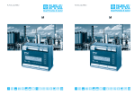
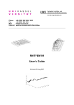
2.6.2 Installation of electronic control unit FC01-Ex
2.6.2.1 Mechanical installation
• The enclosure is installed by 4 retaining screws.
• The blue strips over the screws should be removed to allow the front cover to be eased out
of the enclosure.
PG11 / M20
PG9 / M16
ø5
• The surface mounted enclosure meets protection degree IP54.
240
120
133
3
2
1
G13.5
(blue)
226
90
PG11 / M20
fig. 7
2.6.2.2 Electrical connection
• Take the FC01-Ex equipotential bonding cables (≥1,5 mm2 ) from the monitoring head through
the cable gland 1 (fig. 7) and to the centre grounding system (fig. 6) and connect to terminal
USLKG5.
• Take the cable of the monitoring head through the blue cable gland and connect to the barriers
according to the connection scheme FC01-Ex (fig. 6).
• Take power supply feed through cable gland 2 and further required connection cables
through cable gland 3 (fig. 7) and connect to terminals XV (see connection scheme fig. 6).
18
FC01- Ex | Flow Meter
EX ATMOSPHERE
Definitions and mounting instructions
1 2 3
1
2
3
4
5
6
XV
7
8
9 10
1
XSK
2
3
1
2
3
4
7
8
XTF
M
XAS
1
2
3
4
5
XAO
6
7
8
1
2
3
4
5
XV
- power supply
XSK - calorimetric monitoring head
XTF - keyboard release
XAH
6
7
8
1
2
3
4
5
6
XAS - not released for user
XAO - analogue outputs
XAH - signal outputs
fig. 8
Valid for all plug-in srew terminal strips:
Cable size:
0.14 mm² to 1.5 mm², single or stranded conductor
Stripping length:
6.5 mm
Clamping screw:
M2 (nickel-plated brass)
Contact material: pre-tinned tin bronze XV - Power supply
Connection by 3 pole connector; Amax = 1.5 mm2; 3 x 0.75 mm2 cable recommended
Pin No.
Signal name
Function
1
SGND
general reference ground/shield ground
2
+UV
positive pole of supply voltage
3
-UV
negative pole of supply voltage
XTF - Keyboard release
Connection by 3 pole connector, factory-wired
Jumper 2-3 inserted = keyboerd blocked
19
Flow Meter | FC01- Ex
EX ATMOSPHERE
Definitions and mounting instructions
XAO - Analogue outputs
Connection by 8 pole connector; Amax = 1.5 mm2; LiYCY 2 x 0,25 mm2 cable recommended
Pin selection for analogue outputs V1, V2, C1
Pin No.
Signal name
1
NC
none
2
ANAO1
analogue output 1 - flow
3
ANA1GND
reference potential for analogue output 1
4
SGNDA1
shield ground for analogue output 1 (ungrounded)*
5
SGNDA2
shield ground for analogue output 2 (ungrounded)*
6
ANAO2
analogue output 2 - temperature
7
ANA2GND
reference potential for analogue output 2
8
NC
none
Function
XAH - Limit value signal outputs - relay outputs - change over contacts
Connection by 8 pole connector; Amax = 1.5 mm2, LiYCY 3 x 0.38 mm2 cable recommended
Pin No.
Signal name
Function
1
SGNDL1
shield ground 1
2
LIM1
non-inverted signal output 1 (N.O.)
3
LIM1COM
common change over input 1
4
/LIM1
inverted signal output 1 (N.C.)
5
SGNDL2
shield ground 2
6
LIM2
non-inverted signal output 2 (N.O.)
7
LIM2COM
common change over input 2
8
/LIM2
inverted signal output 2 (N.C.)
XAH - Signal outputs - transistor outputs (NPN, freely connectable)
Connection by 8 pole connector; Amax = 1.5 mm2, LifYCY 4 x 2 x 0,2 mm 2 cable recommended
Pin No.
Signal name
Function
1
/ERROR E
summarized error indication - emitter terminal
2
/ERROR C
summarized error indication - collector terminal
3
/BUSY/PULSE E
availability signal or frequency output -
emitter terminal
availability signal or frequency output -
4
/BUSY/PULSE C
collector terminal
5
LIM2 E
limit value 2 - emitter terminal
6
LIM2 C
limit value 2 - collector terminal
7
LIM1 E
limit value 1 - emitter terminal
8
LIM1 C
limit value 1 - collector terminal
20
* Apply shield on one side only
FC01- Ex | Flow Meter
EX ATMOSPHERE
Definitions and mounting instructions
2.6.2.2.1 Circuit diagram FC01-Ex
Version: 24 V, open collector outputs
1 2 3
6 7 8 9 10
1 2 3 4 5
XV
1 2 3
XSK
1 2 3 4
XTF
M
E/ -
C/+
E/ -
C/ +
LIM2
LIM1
LIM1
C/ +
BUSY/PULSE C/ +
BUSY/PULSE E/ -
5 6 7 8
LifYCY
4x2x0.2 mm2 *
ERROR
E/ -
1 2 3 4
ERROR
ANA2GND
SGNDA2 **
SGNDA1 **
XAH
5 6 7 8
LiYCY
2x0.25 mm2 *
ANA1GND
LiYCY
2x0.25 mm2 *
analogue outputs:
V1
V2
C1
ANAO1
SGND
1 2 3 4
LIM2
XAO
5 6 7 8
ANAO2
XAS
1 2 3 4
Version: 24 V, relay outputs
1 2 3
6 7 8 9 10
1 2 3 4 5
XV
1 2 3
XSK
1 2 3 4
XTF
M
/LIM2
LIM2COM
LIM2
5 6 7 8
SGNDL2
/LIM1
LIM1COM
LIM1
SGNDL1
1 2 3 4
LiYCY
3x0.38 mm2 *
ANA2GND
ANAO2
SGNDA2 **
SGNDA1 **
ANA1GND
LiYCY
2x0.25 mm2 *
analogue outputs:
V1
V2
C1
XAH
5 6 7 8
LiYCY
3x0.38 mm2 *
XAO
1 2 3 4
ANAO1
5 6 7 8
LiYCY
2x0.25 mm2 *
XAS
1 2 3 4
E/ C/+
*
**
emitter terminal
collector terminal
recommended
SGNDA1
ungrounded
SGNDA2
Apply shield on one side only.
}
fig. 9
21
Flow Meter | FC01- Ex
EX ATMOSPHERE
Definitions and mounting instructions
2.6.2.2.2 Electrical connection - frequency output (version FC01-Ex-U1T4)
The quantity-dependent pulse to operate a counter or higher-order control is available at
connector XAH /BUSY E/- and /BUSY C/+ (pins 3 and 4) (see fig. 9 - Circuit diagram FC01-Ex - open
collector output).
Signal ground shall be connected to pin 3 (BUSY E/-) and the driving load to pin 4 (BUSY C/+).
Select cable size ≤ 1.5 mm2 to make the connections.
The shield cables can be connected to connector XAS, pin 3.
Electronic signal processing
If the frequency output of the FC01-Ex is connected to an electronic counter, computer or PLC, the
load current should not exceed 10 mA so as to ensure low level is 0.8 V. The max. admissible voltage
level of 48 V is irrelevant in this connection.
Typical circuit (example 1)
3
4
5
XAO
6
7
8
1
2
3
4
5
XAH
6
7
8
1
2
3
4
5
6
7
iL ≤ 10 mA
2
8
UV
XAS
1
CD
fig. 10
The FC01-Ex driver output comprises an integral safety circuit which when releasing the counter
operating coil will limit overvoltages caused by inductance and convert the energy stored.
The counter should be able of processing a counting frequency of ≥ 10 Hz, as the pulse length is
50 ms (±0.1%) continuously.
22
FC01- Ex | Flow Meter
EX ATMOSPHERE
Definitions and mounting instructions
It should therefore be ensured that the counter can be increased by one during the time
available.
If a separate release network is preferred to the integral network, care should be taken when
processing the max. frequency of 10 Hz to ensure the energy stored in the operating coil has dissipated by the time the counter output is switched on again. The time to do this should be below 40
ms, making due consideration to switching times and pulse variations.
Typical circuit (example 2)
XAS
1
2
3
4
5
XAO
6
7
8
1
2
3
4
5
XAH
6
7
8
1
2
3
4
5
6
7
8
zener voltage
iC
UC
tON
t
iC
UC
tL
tON - switch-on time
tL - time constant of switch-off current
UV <36 V
UV
t
inductance of the
counter drive
fig. 11
Note:
q As there will be a reset pulse available at the output in the moment the supply voltage of the
FC01-Ex is applied, make sure that the counter is switched on delayed or set to zero after it
has been switched on.
23
Flow Meter | FC01- Ex
EX ATMOSPHERE
Definitions and mounting instructions
2.7 Maintenance
2.7.1 Monitoring head CST-Ex
The monitoring head is virtually maintenance-free with media which do not collect on the sensors.
In case of deposits on the sensors these have to be cleaned at the necessary intervals.
void damaging the sensors during cleaning as the explosion protection depends on the
A
intactness of the sensor coating.
2.7.2 Flow Meter FC01-Ex
The Flow Meter FC01-Ex is maintenance free. With regard to software the device is fitted with a wide
range of checking and testing functions described in chapter 7.
24
FC01- Ex | Flow Meter
NORMAL ATMOSPHERE
Definitions and mounting instructions
3 Normal atmosphere - Definitions and mounting instructions
3.1 Measuring procedure
The calorimetric measuring procedure is based on the physics of heat dissipation, i.e. a body with a
temperature higher than its surroundings supplies a medium flowing past that body with energy in the form
of heat. The amount of energy supplied is a function of temperature difference ∆ϑ and mass flow.
Flow Meter FC01-Ex operates on the CTD (Constant Temperature Differential) method:
The temperature difference ∆ϑ between the two sensors is kept constant and the mass flow is determined by measuring the calorific power.
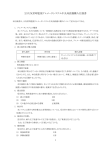
Fig. 12 is a schematic diagram of a CTD method based sensor. Two temperature-sensitive resistors (sensor elements RS and RM) are immersed in the medium. Sensor RM assumes the
temperature ϑM of the medium whilst heater resistor RH heats element RS to temperature ϑS. As a
function of the medium, the temperature differential ϑ∆ = ϑS - ϑM is preselected as a reference
variable by the CTD control with PI characteristics and is kept constant. The required calorific
power is a function of mass flow so that the control variable y of the control can be used for
evaluation.
Major benefits of this method are:
• Fast response, particularly to sudden flow standstill.
• Medium temperature measurement, providing optimum temperature compensation.
• Increased safety because the sensor cannot be overheated during the standstill.
The flow rate is determined by mass flow.
RM
control loop
{
Kp
Kp
medium
m
RS
RH
ϑS
ϑM
Kp
−
+
-x
m: mass flow
w: reference variable (Δϑ)
x : actual value (ϑS-ϑM )
xd
Kp,T n
y
U
w
xd: system deviation
y : control variable
IH: heater current
I
IH
y
fig. 12
25
Flow Meter | FC01- Ex
NORMAL ATMOSPHERED
Definitions and mounting instructions
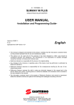
3.2 System description
The system comprises the following hardware functional modules:
Input voltage
DC supply voltage (terminal XV)
User interfaces:
analogue output signal outputs
1 and 2 (terminal XAO)
2-way or 4-way signal outputs (terminal XAH)
Sensor interface:
calorimetric monitoring head (via safety barriers)
Keyboard and display: keypads
liquid crystal display
Micro controller system:
signal processing and monitoring
Power supply DC
User
interface 1
Sensorinterface
calorimetric
monitorin g
head
Micro controller
system
User
interface 2
Keyboa rd and display
26
Input voltage:
DC 19 … 32 V
Keyboard/display:
keypads
LC display
2 x 16 digits
User interface 1:
relay outputs:
transistor outputs:
User interface 2:
analogue outputs
current or voltage
Controller system:
signal processing
I/O - controlling
monitoring
parameter memory
Sensor interface:
calorimetric monitoring head
2 limit values
2 limit values +
1 error indication +
1 busy signal or
frequency output
(software selected)
fig. 13
FC01- Ex | Flow Meter
NORMAL ATMOSPHERE
Definitions and mounting instructions
The power supply is physically isolated between power supply input and system power supply
output. This also applies to the analogue outputs which are physically isolated from each other
as well as from the other electronics and the signal outputs. The signal output channels are
also separate and electrically isolated from the central electronic unit.
There is no electrical isolation between monitoring head and central electronic unit.
Connection of the monitoring heads is by means of precut cable links.
Cables and user interface connections are shown in chap. 2.6.2.2 and circuit diagram 2.6.2.2.1.
System configuration and parameter setting are by means of the keyboard if default values need to
be changed (chap. 5.1.1 and 5.1.2)
This mainly applies signal outputs (switch point setting) and analogue outputs (zero point setting
and scaling).
3.2.1 User interfaces
Signal outputs:
1. R2 - Relay outputs (2 limit values) (optional)
Two-channel physical isolation, relay change over contact
The channels may be assigned in menu “CONFIGURATION”, either individually or in pairs, to the physical quantities of temperature or flow. The switch on
and off values can be set as desired* (yet within the measuring range) for each
contact. Please see chap. 8.5.1 for electrical connection.
2. T4 - Transistor outputs (2 setpoints + 2 status outputs or 1 status output + 1
frequency output)
Four-channel physical isolation, transistor output - collector/emitter freely
connectable
Channel 1: common error signal
Channel 2: busy signal or frequency output
Channel 3 and 4: Both channels may be assigned individually or in pairs to
the physical quantities of temperature or flow. The switch on or off values of
each transistor output can be set as desired.
Please see chap. 8.5.2 for electrical connection.
Analogue outputs: Two-channel physical isolation, current or voltage output
Please see the ordering number to find out whether it is a current or voltage
output.
Output quantities: 0/1 - 5 V FS (option V1)
0/2 - 10 V FS (option V2)
0/4 - 20 mA FS (option C1)
These FS (full scale) output quantities apply to both channels as standard.
20% zero elevation and FS value can be programmed. (See chap. 5.1.1.12)
Shield connections are ungrounded.
The shields of the signal cables should be applied on one side only.
27
Flow Meter | FC01- Ex
NORMAL ATMOSPHERED
Definitions and mounting instructions
Power supply: DC 24 V supply possible.
Internal switch mode power supply with physical isolation of the primary and
secondary side.
Noise emission on the connection cable is limited by circuit design and
filter.
A PTC resistor provides protection from overcurrent. The element automatically resets upon removal of the disturbance or after disconnection of the
supply voltage of the FC01-Ex for approx. 1s (e.g. remove terminal XV)
Please see chap. 8.2.1 for technical characteristics.
28
FC01- Ex | Flow Meter
NORMAL ATMOSPHERE
Definitions and mounting instructions
3.3 Customer calibration
The FC01-Ex functions are purely software functions which do not affect the FC01-Ex hardware.
Generally, a flow characteristic value is assigned to each control variable of the temperature
differential controller (with the variable equalling the heating power) by adjustments as described
within the menu.
Up to 20 trim points can be assigned to the flow characteristic curve, i.e. the calibration range.
This distribution of the trim points being determined by the user within certain ranges of the flow
characteristic curve, resolution and accuracy are determined by that distribution. By extrapolation the
measuring range is expanded beyond the max. flow value by 10% of the upper trim point.
The lower trim point can be optionally set between the zero point of the characteristic curve and the
last but one trim point. If the setting is selected above the zero point, the characteristic curve will be
extrapolated by 10% of the measuring range below the lower trim point or to the zero point. The limit
values and the analogue outputs can be set, or scaled, between these limits.
3.3.1 Options and advantage of customer calibration
Custom designed calibration allows for anomalies within medium or system variations, and the
high repeatability of the measuring procedure makes it possible to measure and indicate flow
conditions with a high degree of accuracy.
This requires that a higher-order measuring unit, or reference quantity, be available, from which the
FC01-Ex is then calibrated and set. The characteristic curve may be determined for each individual
requirement or it can be transferred from one system to another with resultant lower accuracy.
Note:
• A suitable reference instrument is required in each case.
• Adjustment in the field:
Consideration must be made as to the medium and flow
conditions available; reference instrument required.
• FlowVision factory calibration: Calibration in measuring pipes (integral system)
Calibration of: water, various oils, air
3.3.2 Special flow and installation conditions
The measuring system generally implies defined flow conditions, to establish the flow characteristics of
our standard characteristic curves. This requires that certain mechanical dimensions within the pipeline,
such as distances before and after the monitoring head, before or after any bends and changes in pipe
diameter, mounting attitude of the monitoring head (e.g. immersion depth), and any restrictions caused
by turbulent or asymmetric flow be considered.
It is often difficult in compact systems to satisfy these requirements, or to judge the consequences
when they are not fully met (e.g. missing flow straighteners). The FC01-Ex allows the user to
partially or completely eliminate any serious consequences by means of its calibration features.
29
Flow Meter | FC01- Ex
NORMAL ATMOSPHERED
Definitions and mounting instructions
3.3.3 How to achieve higher accuracy
As a result of the relevant physical properties and the characteristics of the monitoring head,
any variations of control variables will be very small and nearly linear in the event of high flow velocities, however with low flow velocities there will be a high signal variation with resultant high nonlinearity. By setting the interpolation trim points in high density, the error can be kept below 1% over
wide distances of the measuring range.
Another influencing factor is the temperature difference selected. (See chap. 4.2.1)
3.3.4 How to achieve the full scale range
As the trim points can be optionally distributed in a fixed sequence on the characteristic curve,
together with the appropriate selection of the sensor temperature, that part of the curve which is
most important for the application can be given a particularly high resolution.
Note:
• The accuracy is a function of how the trim points are density distributed. (See chap. 9 Examples).
3.3.5 Pin-point adjustment (selective accuracy)
If one or several flow values (e.g. flow limits, cooling power limit etc.) are particularly important for the
system, they can be assigned to one trim point each to achieve a high degree of dependability and
accuracy in compliance with the control criteria.
3.3.6. Reproduction of precise measuring instruments
The customer calibrated (-Ex) version of the FC01 allows the user to reproduce expensive measuring instrument data in his characteristic curve. Thus expensive measuring instruments need only be
purchased once, if at all.
3.3.7 Use of standard monitoring heads
(separate heads for gases and liquids)
Monitoring heads are not freely interchangeable with the FC01-Ex, i.e. in the event of a failure the
complete pair monitoring head/electronic control unit must be replaced.
30
FC01- Ex | Flow Meter
TECHNICAL IMPLEMENTATION
of customer calibration
4 Technical implementation of customer calibration
The FC01-Ex can be used to establish a new pipe-depending curve, or to enter or store it as a
theoretical curve.
4.1 Calculation
Interpolation between the trim points is linear. This applies both to the velocity values and the control
variables to be assigned by the user, i.e. the velocity-dependent heating power required to maintain
a constant temperature differential between the medium and the heated probe in the case of a
calorimetric sensor.
Beyond the maximum and minimum trim point, extrapolation is made by 10% each of the
applicable upper measuring range value. As the sensor is not direction-sensitive, the minimum flow
value displayed will be zero.
Maximum number of trim points: 20
Minimum number of trim points: 2
The maximum trim point is assigned to the maximum velocity; the assignable velocity decreases with
a descending trim point index.
Definition:
Vn (velocity assigned to setpoint n)
n = 2 … 20 (trim point index)
Condition for the trim points:
Vn < V(n+1) ..... ≥ 0
4.2 Calibration
4.2.1 Selection of CTD value (temperature differential)
It is possible to select an optional temperature differential setpoint, within a temperature limit of
3.0 °C and 15 °C, providing that 90% Imax of this current heating power is not exceeded, to indicate
the temperature differential at max. flow velocity (90% Imax Y = 36864 Digits).
Error (error 30) will be indicated if this limit is not observed during calibration. The user will then have
to select a lower temperature differential.
As different media have different heat transfer capacities (specific heat) and densities, CTD value
selection also depends on the medium to be measured.
Please see the following table and assignment list for guidance.
Class 1: gases
Class 2: granules, dust and other mixtures containing solids
Class 3: water and similar media, oils and other homogeneous liquids, and liquid mixtures
31
Flow Meter | FC01- Ex
TECHNICAL IMPLEMENTATION
of customer calibration
Note:
q The measuring procedure necessitates a homogeneous distribution of substances/mixture.
Varying mixtures can only be detected by supervisory systems.
The particle size of class 2 media must not exceed 2 mm.
Medium:
Med
Flow velocity:
V
Temperature differential:
∆ϑ
Mass:
m
Specific heat:
c
Density:
ϕ
Assignment table - Medium / Flow velocity / Temperature differential
Class/Medium
Chemical
V [m/s]
∆ϑ [°C]
symbol
ϕ [g/dm3]
c [cal/g °C]
0 °C, 20 °C,
1 bar/14.7 psi 1 bar/14.7 psi
Class 1
a:air
O2
25
10.5
1.293
0.24
25
10.5
1.429
0.219
oxygen
nitrogen
N2
25
10.5
1.25
0.249
nitro oxide
NO
25
10.5
1.34
0.237
carbon monoxide
CO
25
10.5
1.25
0.249
deuterium
25
10.5
0.1798
1.731
fluorine
F2
25
10.5
1.696
0.197
hydrogen
H2
25
10.5
0.08991
3.42
hydrogen bromide
HBr
25
10.5
3.646
0.086
hydrogen chloride
HCl
25
10.5
1.639
0.191
hydrogen fluoride
HF
25
10.5
0.8926
0.348
hydrogen iodide
HI
25
10.5
5.799
0.054
Class 2: We currently don’t have much experience with the use of such media, but generally
the FC01-Ex can certainly be used.
Class 3
4 °C
20 °C
a:tap water
3
3.3
1
1
high-purity water
3
3.3
1
1
seawater
3
3.3
1.03
1
3
3.5
b:water glycol
(1:1 … 2.5:1)
32
FC01- Ex | Flow Meter
TECHNICAL IMPLEMENTATION
of customer calibration
Assignment graph - Medium / Flow velocity / Temperature differential
Medium
Class 1a
Δϑ2= 10.5 °C
Δϑ1= 12.6 °C
Class 1b
Δϑ1=
Class 2a
Δϑ1=
Δϑ2= °C
Class 2b
Δϑ1=
Δϑ2= °C
Class 3a
Δϑ1=3.8 °C Δϑ2= 3.3 °C
Class 3b
Δϑ1=4 °C Δϑ2=3.5 °C
0
1
3
* MBE = upper measuring range value
10
Δϑ2= °C
15
20
25
MBE* V(m/s)
33
Flow Meter | FC01- Ex
TECHNICAL IMPLEMENTATION
of customer calibration
4.2.2 Trim point selection - number and position
Between 2 and 20 trim points can be set.
They are addressed in a “downward” sequence to ensure the user can recognize the trim points still
available by the trim point index indicated.
A reasonable distribution on the characteristic curve depends on the desired accuracy, the required
measuring range or continuity criteria such as differentiating criteria. These issues are addressed
in chap. 9 (Examples).
Generally, there are fewer trim points needed in the upper characteristic curve range than in the lower
range, the reason for this being the flattening characteristic curve (see chap. 9).
Depending on the medium and the measuring range, it is possible to use different procedures in
selecting the trim points.
A linear preselection of the trim points has been provided for in the FC01-Ex. With the appropriate number of trim points set, this procedure achieves good results over the entire velocity range
(5 m/s with water, 25 m/s with air).
A trim point distribution which significantly reduces the measuring error when compared to a
linear distribution, can be determined by the following formula (see 9.2 - Example 2).
MB = ME - MA
AB = MA + (MB x (1 - e-(((SP-1) x g)/SG)))
g = 2,5 x (SP - 1)/SG
AB - trim value [m/s]
SP - trim point No. SP = 1 … SG
MA -
lower measuring range value [m/s]
SG - overall number of trim points
ME -
upper measuring range value [m/s]
g-
distribution coefficient
MB -
measuring range [m/s]
4.2.3 MAX-MIN Calibration procedure
The MAX/MIN calibration procedure has been selected because the critical parameter (max. heating power)
is determined in the computer background after the first calibration step (max. flow velocity).
If too high a temperature differential has been selected for the heater control to indicate, this is displayed as “error 30”. It is then immediately possible to reduce the temperature differential to a value
the controller is able to indicate (see chap. 4.2.1, Selection of CTD value).
It is thus verified and ensured when starting the calibration that the flow characteristics can be displayed, eliminating that a curve must be dropped because its last trim point(s) cannot be indicated.
34
FC01- Ex | Flow Meter
TECHNICAL IMPLEMENTATION
of customer calibration
4.2.4 Zero point, directional discrimination and upper characteristic curve value
The zero point of the characteristic curve and the zero point of flow need not be identical. If the zero
point of the characteristic curve - lowest trim point - is above the zero point of flow, the characteristic
curve is linearly extrapolated down by 10% MBE (= upper measuring range value) so as to extend
the calibration range of the FC01-Ex.
However, the extrapolation is only effected to the theoretical zero point as the measuring system does
not operate in a direction-selective way.
If the zero point of flow and the zero point of the characteristic curve are identical, the control
variable should be increased by 300 to 400 digits to suppress the convection-dependent variation of
the zero point.
In the same way that the calibration range can be extrapolated downward by 10% MBE, so can the
upper calibration range be extrapolated by 10% MBE above the upper trim point. Error indication
because of minor over limits of the upper calibration range values can thus be eliminated. The extended
characteristic range will then be fully available when determining the analogue output, the limit values
and the bar graph.
4.2.5 New curve / Old curve
4.2.5.1 New curve
The following automatic processes have been provided for to facilitate and accelerate the calibration or
manual entry of a new curve.
1. Preloading of zero point control variables
As a result of parasitic heat transfer points a big part (approx. 50%) of the heating power is not
transported through the medium but rather through the housing and the electrical cables. The heating power control variable with zero flow has already a value above 25,000 digits.* Preloading the
setting value for the lower trim point with that value obviates the need for passing through a wide
setting range (timesaving benefit).
* Provided the temperature differential has been selected appropriately (see chap. 4.2.1 for
recommended values).
2. Linear preloading of interim values for velocity and control variable
The calibration range left between the last addressed and established trim point and the zero point is
linearly divided among the remaining trim points. This applies both to velocity quantities and control
variables. It generally ensures that only a small calibration range needs to be passed (provided that
item 1. has been satisfied).
In this operating mode - new curve - an already existing curve (old curve) would be deleted. If the
new curve is completely entered by hand, it is necessary to enter the TK reference temperature (see
5.1.1.4.7) when quitting the menu.
The TK reference temperature is the medium temperature at which the curve was established under
normal operating temperature conditions.
If the calibration of a new curve is made selecting temperature differences which are essentially smaller
than the values recommended, the zero point on the characteristic curve will be displaced towards
smaller control variables. It may happen then that the first trim value is below or on the preloaded zero
point value, in which case the software will provide that the initial values for further control variables
are below the established preceding value.
35
Flow Meter | FC01- Ex
TECHNICAL IMPLEMENTATION
of customer calibration
4.2.5.2 Old curve
In this operating mode, each trim point can be corrected without jeopardizing other existing data.
Changes are limited by the general calibration conditions. This means that the values assigned to
a trim point can never be higher than the values assigned to the trim point above, or lower than the
quantities assigned to the trim point below.
Caution!
Changes/expansions of old curves must only be made whilst maintaining the temperature
differential.
4.2.6 Transfer of C- and T values - Re-establishment of T value
As the monitoring heads are factory preset for air or water, their C- and T values apply only to those
media.
When the heads are used in gases or gas mixtures similar to air (see table page 32), these values
can be transferred. The same applies to heads monitoring water.
In that case the temperature difference (water 3.3 °C, air 10.5 °C) must be set in the CUSTOMER
TRIM menu to calibrate a characteristic curve.
The following medium characteristic quantities should however harmonize as far as possible:
a. density ϕ
b. specific heat c
When other media are used, the C value may be transferred, but the T value should be separately established and set for recording the new curve at T = 50.
4.2.6.1 Establishing the T value - general
The T value should be established at a velocity in the upper third of the calibration range.
When recording the characteristic curve, the temperature and the control variable at a trim point
located in the upper third of the characteristic curve (70 - 80% Vmax) should be noted.
T1 = . . . , . °C
medium temperature when recording the new curve
YT1 = . . . . . digits
control variable
VT1 = . . , . . m/s
flow velocity at temperature T1
Control variable YT2 is then established at the same flow velocity (VT2 = VT1), ideally at the highest
medium operating temperature.
Conditions:
VT1 = VT2
T2 > T1
The following quantities are recorded:
36
T2 = . . . , . °C
upper setting temperature of the medium
YT2 = . . . . . digits
control variable with T2
FC01- Ex | Flow Meter
TECHNICAL IMPLEMENTATION
of customer calibration
The following quantities are recorded:
T = 50 + (YT2 - YT1) / (T2 - T1)
The resultant T value is filed in the configuration menu under SENSOR SELECT - TYPE CALORIMCODE T… .
4.2.6.2 Establishing the new T value
At first, a new curve has to be recorded by setting the T value in the SENSOR SELECT menu at
T = 50.
With heads monitoring water or air (see introduction to this section) it is possible to use the C value
if similar media are to be monitored. It is necessary to set C1000 as basic value if the characteristic
quantities of a medium cannot be assigned to a medium group.
After setting the C- and T values, the number of trim points and the temperature difference shall be
defined in the CUSTOMER TRIM menu.
Record the new curve as described, observing constant temperature conditions (T1, YT1, VT1 as
described).
After establishing and storing the new curve, the medium shall be heated to setting temperature (T2).
Then return to the CUSTOMER TRIM menu and select option old curve.
Address the trim point the control variable of which you wish to establish at temperature T2 and the
same velocity as when recording the new curve.
Compare the following values displayed:
TRIM POINT …
V = . . , . . m/s
Y = . . . . . (YT1) with the values noted.
These values shall still be assigned to the old curve which was recorded at temperature T1. Then set
velocity V at the higher temperature T2.
Activate the automatic control variable determination in menu TRIM ACTIVE.
When the FC01-Ex has determined the new Y value, it is displayed and recorded (YT2) as it is needed
for subsequently calculating the T value.
Temperature T2 (please note down) which will also be included in the calculations is displayed before
the calibration menu is quitted.
Then quit the menu without storing the data (s UP or t DOWN) to prevent overwriting the old
curve.
The new T value is calculated by inserting the values determined for YT1, T1, YT2, T2 into the formula.
Set the new T value in the configuration menu under SENSOR SELECT.
37
Flow Meter | FC01- Ex
TECHNICAL IMPLEMENTATION
of customer calibration
4.2.7 Expanding the characteristic curve
The characteristic may easily be extended upward when the temperature difference has been selected so as to provide sufficient reserve heating power (normally ensured by the curve getting flat at
higher velocities).
Note:
• Consider some reserve for the heating power (4.2.1, Selecting the temperature differential) when
establishing a curve that is intended subsequently to be extended.
The extension can be made either by manually entering quantities Y and V to be assigned, or in menu
point TRIM ACTIVE giving a flow velocity.
Note:
• It is not possible to include new trim points in an existing characteristic curve!
38
FC01- Ex | Flow Meter
OPERATION
5 Operation
5.1 Operating system
Clear menu-driven control, via keyboard and display, enables easy definition of parameters and
configuration. This provides high system flexibility, making the FC01-Ex the optimum solution for a
wide variety of measuring, monitoring and display tasks.
All functions are distributed on the three following menu levels:
See Appendix 5 listing all functions available.
MAIN LEVEL (MENU)
CONFIGURATION LEVEL (MENU)
PARAMETER LEVEL (MENU)
Touch switches
Setting and configuration is by means of three front touch switches: M MODE, s UP and
t DOWN.
Caution!
The FC01-Ex can only be set or operated when connector XTF (keyboard release) is removed!
M
MODE
UP
FC01-Ex
Flow Controller
DOWN
fig. 14
39
Flow Meter | FC01- Ex
OPERATION
Menu paging
The next menu option is selected by pressing M MODE (forward paging).
Pressing M MODE after the last menu option will cause skipping to the first option of the menu.
Calling a menu option
Simultaneously pressing s UP and t DOWN calls the selected menu option, or causes skipping to
the selected submenu.
Entry of numerals
Some menu options require numerical values to be entered. After selecting the appropriate menu
option, the value indicated can be changed by pressing s UP or t DOWN.
Each time s UP or t DOWN are pressed, the value indicated will be increased and reduced
respectively, by one numeral skip. The longer s UP or t DOWN are pressed, the faster the increase
or reduction.
Transfer of entries
Pressing M MODE transfers the set value or the selected menu option to a volatile memory. A permanent transfer of settings and values is only effected when quitting the menu, after a plausibility
check of all entries.
Afterwards the data will be available even after repeated on/off operation of the FC01-Ex.
Deleting data
Selected data such as MIN and MAX values can be deleted or reset by simultaneously pressing
s UP and t DOWN.
40
FC01- Ex | Flow Meter
OPERATION
5.1.1 Configuration
The CONFIGURATION menu serves to adjust the FC01-Ex to its application within the entire
system.
During system configuration, measuring operations are not possible (see Appendix 1).
Configuration possibilities are:
5.1.1.1 Selection of monitoring head (menu option: SENSOR SELECT)
The menu covers only one calorimetric monitoring head type so that it is not necessary to enter
further details.
5.1.1.2 Monitoring head data (menu option: SENSOR CODE)
To operate the FC01-Ex it is necessary to set sensor-specific characteristics.
These characteristics are specified by the sensor code which together with the monitoring head type
number is marked on the monitoring head housing.
Setting is menu driven in two steps:
1. Setting of the C characteristics
C range: 700 … 1300
2. Setting of the T characteristics
T range: 01 … 99
5.1.1.3 Medium selection (menu option: MEDIUM SELECT)
This menu option is used to select the medium in which the Flow Meter is used.
The following media are called:
* GAS
* FLUID
5.1.1.4 Custom designed calibration (menu option: CUSTOMER TRIM)
5.1.1.4.1 Access to menu option CUSTOMER TRIM
Access to the calibration menu is provided by answering CUSTOMER TRIM? with yes and
entering the fixed 3-digit ACCESS CODE.
Note:
ACCES CODE to be entered ➞ 987
Entering an incorrect code will cause skipping to the next option of the configuration menu; another
access to CUSTOMER TRIM can only be started after running through the entire configuration
menu.
41
Flow Meter | FC01- Ex
OPERATION
5.1.1.4.2 Old curve / New curve
If the inquiry about the CHARACTERISTIC of the curve is answered by new, the selected trim points
are assigned to default data (see 4.2.5).
If a filed curve needs to be corrected or expanded, the above inquiry should be answered by old.
In that case, the trim points already stored will not be affected.
This menu option does not apply if a custom designed curve has not yet been entered.
5.1.1.4.3 Number of trim points
The number of trim points NUMBER OF TRIM POINTS can be selected between 2 and 20 (see
chap. 4.2.2).
5.1.1.4.4 Determining the temperature differential
The TEMPERATURE DIFFERENCE setpoint can be set at 3 °C ≤ ∆ϑ ≤ 15 °C. The limit conditions
defined in chap. 4.2.1 shall be observed.
5.1.1.4.5 Automatic calibration
After the temperature difference has been determined, the trim point with the highest number will
appear when the first adjustment is made. It corresponds to the number of trim points selected
(TRIM POINT. . ).
The highest flow velocity shall be assigned to that trim point. The flow velocity can be set between
0.00 m/s and 90.00 m/s.
Before starting the automatic calibration by simultaneously pressing s UP and t DOWN, the flow
velocity at which the trim point shall be determined must have been available at the sensor for more
than 10 seconds.
The heating period required by the measuring procedure is started before the first trim point is set.
The remaining heat-up time is displayed in seconds (REST TIME . . sec. ).
Once the heat-up period is over, the FC01-Ex will start the setting routine for the set flow velocity.
The calibration time is 20 seconds.
Note:
• B ating power cannot be correctly determined.
The display will therefore indicate index quantity xd = ..... for constant flow. During the calibration
time of 20 seconds, that quantity should be between -0.10 and +0.10.
Upon completion of the calibration, the program will return to menu option TRIM POINT . . with the
heating power determined.
The integer value determined will be flashing on the display.
After confirmation, a selection menu is inserted allowing the calibration of the next, same or previous
trim point (not with the first trim point).
When the next trim point is selected, the trim point number is reduced by one. The trim point is again
assigned to a flow velocity, and the automatic calibration is started.
This procedure is repeated until the last trim point (TRIM POINT 01) has been calibrated.
The customer designed characteristic curve has now been established and entered.
5.1.1.4.6 Manual calibration
42
FC01- Ex | Flow Meter
OPERATION
If a custom designed characteristic curve has already been established and the curve shall be duplicated on an other FC01-Ex, it is possible to enter the data for the various points by hand.
The method is largely identical with that for automatic calibration.
The heating power belonging to the flow velocity is not determined automatically but rather entered
on the FC01-Ex by hand.
It is also possible to make the calibration combining automatically determined and theoretically
calculated trim points.
5.1.1.4.7 Calibration temperature
After confirmation of the last trim point, TRIM IS READY! is displayed.
The second line on the display will show the medium temperature in °C at which the calibration was
made. With automatic calibration, the calibration temperature is displayed non-flashing and cannot
be changed by hand.
If the calibration data were entered by hand, the calibration temperature must also be set by hand.
In that case the temperature value will be flashing.
Note:
• The medium temperature must be kept constant over the entire calibration process!
5.1.1.4.8 Storing the characteristic curve
Before quitting the CUSTOMER TRIM menu, the FC01-Ex shall be informed whether the custom
designed curve determined or entered shall be stored in a permanent (touch switch M) or volatile
way (s UP or t DOWN).
If the characteristic curve shall be stored in a volatile way, it will be deleted upon failure or power
disconnection.
Note:
• If a power failure occurs during the calibration, the entire calibration must be repeated!
5.1.1.4.9 Potential errors during the calibration
43
Flow Meter | FC01- Ex
OPERATION
All errors found during the calibration are indicated with their relevant number.
If one of the following errors occurs, it is not necessary to repeat the entire calibration but rather the
calibration of the trim point where the error occurred.
Error
Cause
Rectification
No. 10
Sensor not connected, or cable between
FC01-Ex → and sensor defective;
or defective sensor
Check cable or replace the
pair electronic control unit +
monitoring head.
No. 21
Medium temperature too high
No. 20
Medium temperature too low
No. 30
Temperature difference selected is too high
Correct temperature difference.
5.1.1.5 Limit switch combinations (menu option: LIMIT SWITCHES)
The FC01-Ex comprises two limit switches which are assigned to the physical quantity/quantities to
be monitored in menu “LIMIT SWITCHES”.
The following four combinations are available:
* LS1 → F
LS2 → F
Limit switch 1 →
flow rate
Limit switch 2 → flow rate
* LS1 → T
LS2 → T
Limit switch 1 → medium temperature
Limit switch 2 → medium temperature
* LS1 → F
flow rate
Limit switch 2 → medium temperature
* LS1 → T
Limit switch 1 →
LS2 → T
Limit switch 1 → Limit switch 2 → LS2 → F
medium temperature
flow rate
Mode of operation, limit value and hysteresis of the limit switches are set in menu “PARAMETER
SELECTION”.
Caution!
Menu option “LIMIT SWITCHES” may influence data in the parameter selection menu (see chap.
5.1.1.14, Quitting the configuration menu).
44
FC01- Ex | Flow Meter
OPERATION
5.1.1.6 Flow rate unit (menu option: FLOW UNIT)
This menu option is used to set the desired flow rate unit:
* METRE/SEC [m/s]
*
FEET/SEC. [FPS]
* PERCENT [%]
*
BLANK [no unit]
Any further entries relating to flow rate (e.g. limit value, analogue output etc.) refer to that unit.
Standard percent is displayed when BLANK (no unit) is selected.
When the flow rate unit is changed, all configuration and parameter data relating to flow rate will
automatically be converted!
5.1.1.7 Medium temperature unit (menu option: TEMP. UNIT)
This submenu is used to select medium temperature unit.
Options are:
* GRAD CELSIUS [°C]
* GRAD FAHRENHEIT [°F]
* KELVIN [K]
All other entries relating to the medium temperature (limit value, analogue output etc.) refer to the
unit selected there. When the temperature unit is changed, all configuration and parameter data
relating to medium temperature will automatically be converted.
5.1.1.8 Display (menu option: DISPLAY SELECT)
The FC01-Ex enables the user to define certain points of the display.
When the first line of the LC display in the main menu indicates the flow rate in the unit selected as
well as the medium temperature in °C, °F, or K, it is possible to select the 2nd line from the following
menu options (see chap. 5.1.1.16).
* BARGRAPH
Totalizer:
* LITRE/SECOND [l/s]
*
LITRE [l] * LITRE/MINUTE [l/min]
*
METRE 3 [m 3 ]
* METRE / HOUR [m /h]
*
FEET 3 [F3 ]
* GALLONS°/MINUTE
*
GALLONS° [° = US-GALLONS]
3
3
Where totalizer function has been selected, the totalizer will start at zero counting in the unit selected
(litre, m3 or gallons).
45
Flow Meter | FC01- Ex
OPERATION
When the display changes from m3 to litre or gallons, or from litre or gallons to m3, the value already
counted will be converted.
The content of the totalizer is deleted by simultaneously pressing s UP and t DOWN, or when the
max. display value (99999999.9 l, m3 or gallons) is reached. In both cases, the totalizer will restart
from zero.
Caution!
The content of the totalizer is deleted in the event of power failure or disconnection of the power
supply!
Skipping to the menu BARGRAPH or PIPE SIZE is effected depending on the selected menu
option.
5.1.1.9 Bar graph (menu option: BARGRAPH)
This menu option allows the user to set the bar graph as desired. The following settings should be
made:
* FLOW / TEMP =
(bar graph assignment: flow rate/medium temperature)
* ZERO =
(initial value of the bar graph)
* FS =
(final value of the bar graph)
Independent of its assignment, the bar graph has a constant resolution of 10 segments.
When entering the initial or final value, the user should observe a reasonable resolution!
The bar graph also comprises the representation of the limit switch(es) as far as they can be indicated in the bar range selected.
The representation of the limit switches in the bar graph depends on the switch-on value of the limit
switch.
For representation details see chap. 6.2.1 (Operating data).
Example:
Limit switch assignment:
LS1 → F LS2 → T
Switch-on value LS2:
23 °C
Analogue bar graph assignment:
medium temperature
Initial value - analogue bar graph:
20 °C
Final value - analogue bar graph:
30 °C
Instantaneous temperature value:
25 °C
→ resulting in the analogue bar graph display shown below (see fig. 15)
5.1.1.10 Pipe size (menu option: PIPE SIZE)
To display a flow volume/time unit or a totalizer function it is necessary to indicate the pipe
diameter to calculate mass flow.
This is provided by selecting the pipe diameter in menu option PIPE SIZE comprising pipe
diameters from 10.0 to 460.0 mm.
46
FC01- Ex | Flow Meter
OPERATION
20 °C 21 °C
25 °C
29 °C 30 °C
T
LS2 ON
fig. 15
5.1.1.11 Frequency output (menu option: FREQUENCY OUTPUT)
The totalizer function of the FC01-Ex has been expanded by the output of proportional quantity
pulses. The function can only be displayed by version FC01-Ex-U1T4 (open collector outputs).
The proportional quantity pulses have been determined as follows:
pulse/quantity (totalizer)
Example: 1 pulse / 10.0 [litre]
The frequency output will supply 1 pulse per 10 litres (totalized quantity)
When the quantity-proportional pulses are assigned, the frequency of the frequency output must no
exceed 10 Hz. The limits that can be displayed are determined by the flow velocity range and the
pipe diameter.
Potential setting range of the frequency output: 1 pulse per 0.1 … 999.9 [Litre], [m3 ], [Gallons]
Behaviour of the frequency output when the max. frequency is exceeded
The max. frequency being exceeded will not cause the measurement to stop but will rather cause the
error output to signal error 60 on the display. This error is included in priority group III.
If a combination of priority III errors occurs simultaneously, they are indicated or stored in the error
memory observing the following sequence:
Error No. 20, 30, 31, 60, 40, 41.
Behaviour of the frequency output when the measurement is stopped
When the measurement is stopped (as caused by priority II error and calling the configuration or
parameter selection menus), the pulses for the quantity already counted will be available. Thereafter
the output of pulses will be stopped, with the frequency output becoming high-resistive until the
measurement is restarted.
Behaviour of the frequency output when the content of the totalizer is deleted
The content of the totalizer may be deleted by simultaneously pressing s UP and t DOWN in the
main menu
As the frequency output refers to the content of the totalizer, although its operation is not dependent on the content of the totalizer, a totalized quantity that is smaller than that set per pulse will not
be lost.
This means that only the content of the totalizer is deleted.
47
Flow Meter | FC01- Ex
OPERATION
5.1.1.12 Analogue output - flow rate (menu option: ANA OUT FLOW)
This menu option allows adjustment of the flow rate analogue output specifically to the requirements of
the entire system.
Options are:
* OFFSET =
% (FS) (0/4 … 20 mA, 0/1 … 5 V, 0/2 … 10 V)
* ZERO =
(initial value 0(20) % corresponds to a flow rate of … [m/s] [%])
* FS =
(100% final value corresponds to a flow rate of …[m/s] [%])
When entering the initial value, the user should observe a reasonable resolution!
With a flow volume/time unit selected in menu DISPLAY SELECT and when setting the initial and end
values, the pertinent flow volumes will also be indicated.
5.1.1.13 Analogue output - medium temperature (menu option: ANA OUT TEMP.)
In conformance with the configuration “Flow rate analogue output” it is possible to adjust the medium
temperature analogue output to the requirements of the entire system.
Options are:
* OFFSET =
% (FS) (0/4 … 20 mA, 0/1 … 5 V, 0/2 … 10 V)
* ZERO =
(initial value 0(20) % corresponds to a medium temperature of … [°C] [°F] [K])
* FS =
(final value 100% corresponds to a medium temperature of … [°C] [°F] [K])
When entering the initial or final value, the user should observe a reasonable resolution.
5.1.1.14 Quitting the configuration menu
Upon configuration of the analogue outputs, the menu may be quitted or reset to the start (SENSOR
SELECT).
To quit the configuration menu, the controller will check the data entered for plausibility.
“CONFIG. OK!” is indicated when the data are found to be correct. The menu may then be quitted by
pressing M MODE.
Errors found during the plausibility check are indicated in the following sequence of priority.
Priority of entry errors in the CONFIGURATION menu:
* ERR. A-OUT FLOW OUT OF RANGE
(flow analogue output outside measuring range)
* ERR. A-OUT FLOW ZERO ≥ FS
(initial value ≥ final value with flow analogue output)
* ERR. A-OUT TEMP. OUT OF RANGE
(temperature analogue output outside measuring range)
* ERR. A-OUT TEMP. ZERO ≥ FS
(initial value ≥ final value with temperature analogue output)
* ERR. BARGRAPH OUT OF RANGE
(bar value outside measuring range)
* ERR. BARGRAPH ZERO ≥ FS
(bar initial value ≥ bar final value)
48
FC01- Ex | Flow Meter
OPERATION
The menu can only be quitted after correction of the error(s). To do this, return to the beginning of
the configuration menu by pressing t DOWN or s UP and select the menu option with the incorrect
entry for correction.
Caution!
If during the configuration data are affected which are accessible in the parameter selection menu (which may be the case for the options Medium Selection and Limit Switch
Assignment), the option “PARAMETERS” in the main menu will be flashing.
In this event it is imperative to branch into parameter selection menu to set the data in
conformance with the desired application.
Example: C hanging the limit switch assignment
to LS1 → F / LS2 → F
from
LS1
→
F
/
LS2
→
T
affects LS2 ON = 0.00
Parameter data:
LS2 OFF = end of measuring range
Reason:
Changing the physical assignment of limit switch 2 will adjust its switch-on
and switch-off values to the new assignment (flow rate).
An overview of the configuration menu and a summary of the measuring ranges and menus available
for the sensor type selected are shown on the following pages.
49
Flow Meter | FC01- Ex
OPERATION
5.1.1.15 Configuration menu
Configuration
CONFIGURATION
SENSOR SELECT
▲
and
▼
submenu
sensor selection
▲
and
▼
submenu
medium selection
▲
and
▼
submenu
customer trim
▲
and
▼
submenu
LS combination
▲
and
▼
submenu
flow unit
▲
and
▼
submenu
temperature unit
▲
and
▼
submenu
display selection
▲
and
▼
submenu
analogue flow
▲
and
▼
submenu
analogue temperature
M
CONFIGURATION
MEDIUM SELECT
M
CONFIGURATION
CUSTOMER TRIM
M
CONFIGURATION
LIMIT SWITCHES
M
CONFIGURATION
FLOW UNIT
M
CONFIGURATION
TEMP. UNIT
M
CONFIGURATION
DISPLAY SELECT
M
CONFIGURATION
ANA OUT FLOW
M
CONFIGURATION
ANA OUT TEMP.
M
END OF CONFIG.?
M→yes ▲ or ▼ → no
M
▲
or
▼
Config. plausible?
yes
CONFIG. OK!
PUSH M
M
return (to main menu)
50
no
ERROR CONFIG.
▲
or
▼
FC01- Ex | Flow Meter
OPERATION
5.1.1.16 Configuration submenus
Conf.
M
SENSOR CODE
T 50
M
SENSOR CODE
C1000
M
submenu
sensor selection
SENSOR SELECT
TYPE CALORIM.
▲
or
▼
Conf.
Conf.
M
submenu
medium selection
MEDIUM SELECT
GAS
M
MEDIUM SELECT
FLUID
▲
or
▼
▲
or
▼
Conf.→ return to configuration menu
51
Flow Meter | FC01- Ex
OPERATION
Customer trim
CUSTOMER TRIM?
M ➞ yes ▲ or ▼ ➞ no
▲
or
▼
▲
or
▼
▲
or
▼
▲
or
▼
M
ACCESS CODE
CODE = …
M
set code
no
code OK?
yes
#
CHARACTERISTICS
M ➞ old ▲ or ▼ ➞ new
or
▲
M
▼
NUMBER OF TRIM
POINTS = . .
set number of
trim points
M
TEMPRATURE
DIFFERENCE =....
set temperature
difference
M
M
M
▲
yes TRIM IS READY!
last point?
or
TEMP = ….,. °C **
no
▼
TRIM POINT …
DATA OK! M =NEXT
▼ = SAME ▲ = BACK
▲
or
▼
▲
or
▼
V = ..... m/s * Y = .....
M
data to be
permanently stored!
▲ or ▼
END! STORE D ATA ?
M ➞ yes ▲ or ▼ ➞ no
switch ?
set V (m/s)
M
▲
or
TRIM POINT …
▼
V = ..... m/s Y = ..... *
DATA NOT PLAUS.
▼ = SAME ▲ = BACK
yes
no
Calibr. data plausible!
set Y
M
TRIM POINT …
V = ..... m/ s Y = .....
M
switch ?
▲ and ▼
TRIM ACTIVE! …
xd = .....
no
Error 30
*
**
#
52
wait until calibration
is completed
▲ or ▼
flashing mode
flashing if value
can be set
only if calibration data
are available
Retur n to menu calling!
setting er ror?
yes
yes
no
ERROR . .
PUSH ▲ or ▼
LIMIT SWITCHES
LS1 → F LS2 → F
FLOW UNIT
METRE/SEC (m/s)
TEMP. UNIT
CELSIUS (°C)
submenu
limit switch
combination
submenu
flow unit
submenu
temperature unit
Configuration submenus (cont’d)
▲
▲
▲
▼
▲
TEMP. UNIT
FAHRENHEIT (°F)
▼
or
▼
▲
or
▼
M
or
Conf.
▲
M
▼
Conf.
or
M
FLOW UNIT
PERCENT (%)
Conf.
▼
M
or
Conf.
or
M
M
LIMIT SWITCHES
LS1 → T LS2 → T
Conf.
Conf.
TEMP. UNIT
KELVIN (K)
FLOW UNIT
FEET/SEC. (FPS)
LIMIT SWITCHES
LS1 → F LS2 → T
▲
▲
▲
or
M
Conf.
or
M
Conf.
or
M
Conf.
▼
▼
▼
or
▲
or
M
Conf.
▲
▼
▼
Conf.→ return to configuration menu
FLOW UNIT
BLANK (no unit)
LIMIT SWITCHES
LS1 → T LS2 → F
M
Conf.
FC01- Ex | Flow Meter
OPERATION
53
54
submenu
analogue
temperature
submenu
analogue flow
submenu
display selection
Conf.
M
ANA OUT TEMP.
FS = 85.0 °C
M
ANA OUT TEMP.
ZERO = -10.0 °C
M
ANA OUT TEMP.
OFFSET = 20% (FS)
Configuration submenus (cont’d)
Conf.
M
ANA OUT FLOW
FS = 3.5 m/s
M
ANA OUT FLOW
ZERO = 0.5 m/s
M
ANA OUT FLOW
OFFSET = 0 % (FS)
▲
▲
▲
▲
▲
▲
▲
▲
▼
▼
▼
▼
▼
▼
▼
or
▼
DISPLAY SELECT
GALLONSϒ
or
DISPLAY SELECT
METRE3
or
DISPLAY SELECT
LITRE
or
DISPLAY SELECT
GALLONSϒ/MINUTE
or
DISPLAY SELECT
METRE3/HOUR
or
DISPLAY SELECT
LITRE/MINUTE
or
DISPLAY SELECT
LITRE/SECOND
or
DISPLAY SELECT
BARGRAPH
M
M
M
M
M
M
M
M
no
▲
Conf.
or ▼
M
M
Conf.
Conf.
M
FREQUENCY OUTPUT
PULSE/..........(unit)
FREQUENCY OUTPUT?
M → yes other → no
yes
BARGRAPH
FS = 20.0 m/s
M
BARGRAPH
ZERO = 10.0 m/s
° US-GALLONS
Conf.→ return to configuration menu
Conf.
Totalizer function?
M
PIPE SIZE
52.5 mm
M
BARGRAPH
TYP=FLOW or TEMP
Flow Meter | FC01- Ex
OPERATION
FC01- Ex | Flow Meter
OPERATION
5.1.2 Parameter selection
After configuration of the FC01-Ex in conformance with its application (configuration menu), it is
possible to set parameters (e. g. limit values).
During parameter setting, measuring operations are not possible (see Appendix 1).
The following parameters may be set in the Parameter selection menu:
5.1.2.1 Measuring time (menu option: MEAS. TIME)
The measuring time can be set between 1 and 30 sec., referring both to flow rate and medium
temperature.
The effect of the measuring time may be compared to that of a low-pass filter; it is used to determine
the average of the last measured values after each measurement.
The set measuring time does not influence the measuring rate and display up-date.
5.1.2.2
Limit switch 1 - switch-on value (menu option: LS1 ON = ......)
Limit switch 1 - switch-off value (menu option: LS1 OFF = ......)
Depending on the configuration (see configuration menu) limit value 1 may be set either for flow
rate or medium temperature.
The limit value may be set over the entire measuring range and is always related to the display
value.
Limit switch up-date is by measuring rate, independent of the set measuring time.
The hysteresis is determined by entering different switch-on and switch-off values. Its magnitude
should be reasonably adjusted to current operating conditions.
A specific definition of the operation (closed-current or open-circuit principle) may be dropped by
separately entering the switch-on and switch-off value of the limit switch, because the definition is
deducted from the switch-on and switch-off value.
Example 1: Switch-on value lower than switch-off value
switch-on value
∞
0
ON
OFF
switch-off value
hysteresis
measured value
switching condition
of limit switch 1
fig. 16
55
Flow Meter | FC01- Ex
OPERATION
Example 2: Switch-on value higher than switch-off value
switch-off value
switch-on value
∞
0
ON
hysteresis
measuring value
switching condition
of limit switch 1
OFF
fig. 17
With limit switch 1 set for flow rate and a flow volume/time unit selected in menu DISPLAY
SELECT, and when setting the switch-on and switch-off value, the pertinent flow volumes will also
be indicated.
5.1.2.3
Limit switch 2 - switch-on value (menu option: LS2 ON = ......)
Limit switch 2 - switch-off value (menu option: LS2 OFF = ......)
See limit switch 1!
5.1.2.4 Scaling factor (menu option: FLOWSCALE*)
The scaling factor influences flow rate indication.
The factor, which may be set between 0.01 and 9.99, allows flow rate indication changes (increasing or reducing the measured value in the display).
For example, the scaling factor may be used to indicate the average flow rate in the pipeline rather
than that available at the sensor.
5.1.2.5 Quitting the parameter selection menu
Before the parameter menu can be quitted, the controller will conduct a plausibility check of the
data entered.
“PARAMETERS OK!” is indicated when the data are found to be correct. The menu may then be
quitted by pressing M MODE.
Errors found during the plausibility check are indicated in the following sequence of priority.
Priority of entry errors in the PARAMETER SELECTION menu:
* ERROR LS1
OUT OF RANGE
switch-on and switch-off value for limit switch 1 outside measuring range.
* ERROR LS2
OUT OF RANGE
switch-on and/or switch-off value for limit switch 2 outside measuring range
56
FC01- Ex | Flow Meter
OPERATION
* ERROR LS1
ON = OFF
switch-on value for limit switch 1 equals switch-off value for limit switch 1
* ERROR LS2
ON = OFF
switch-on value for limit switch 2 equals switch-off value for limit switch 2.
The menu can only be quitted after correction of the error(s). To do this, return to the beginning
of the parameter selection menu by pressing t DOWN or s UP and select the menu option with
the incorrect entry for correction.
An overview of the parameter selection menu is shown on the following page.
57
Flow Meter | FC01- Ex
OPERATION
5.1.2.6 Parameter selection menu
parameters
PARAMETERS
MEAS. TIME = 3 sec
M
PARAMETERS
LS1 ON = 1.24 m/s
M
PARAMETERS
LS1 OFF = 1.50 m/s
M
PARAMETERS
LS2 ON = 73.0 °C
M
PARAMETERS
LS2 OFF = 68.5 °C
M
PARAMETERS
FLOWSCALE * 1.1 2
M
END OF PARAM. ?
M→yes ▲ or ▼ → no
M
▲
or
▼
Paramet. plausible?
yes
PARAMETERS OK!
PUSH M
M
return (to main menu)
58
no
ERROR P ARAMET .
▲
or
▼
FC01- Ex | Flow Meter
OPERATING PHASES
6 On-line phases
6.1 Switch-on performance
Upon power application, POWER ON TEST, will be shown on the display for approx. 1 sec, with
the software version number being indicated in the second line.
During this period, the integral controller will conduct test routines (see chap. 7.1, Test and diagnosis).
If during the test no error was found, the display will indicate HEATING UP.
The FC01-Ex will then be in the heating up period required for the measuring procedure.
6.2 Measuring cycle
Upon completion of the heating up period and availability of the first measured value, the
display will change to measuring cycle, and the user interfaces such as analogue outputs or limit
switches will be up-dated.
The following operating data may be retrieved in the main menu during the measuring cycle:
6.2.1 Operating data
6.2.1.1 Measured value(s)
Flow rate and medium temperature are indicated by the units selected in the upper line of the LC
display.
The lower line of the display will optionally show the switching condition of the limit switches and an
analogue bar with a 10-segment resolution, or the flow volume/time unit pertinent to the indicated
flow rate or the totalized flow volume (totalizer function).
The analogue bar has different meanings, depending on its configuration (see para. 5.1.1.9 - menu
option BARGRAPH).
The limit switches are identified according to their physical assignment, i.e. by F for flow rate
and T for medium temperature, at the first or last place of the second line on the display.
If F and T are shown reversed, the limit switch is in the switch-on condition.
Limit switches lying within the analogue bar range are also represented at the appropriate place
of the analogue bar.
59
Flow Meter | FC01- Ex
OPERATING PHASES
The following figures show the display variants under the menu option “Measured value(s)”
(chap. 5.1.1.8 - menu option DISPLAY SELECT and 5.1.1.11 - menu option FREQUENCY OUTPUT).
5.0 m/s
F
-13.5 °C
F
T
inverse representation
“switch-on condition”
F
5.0 m/s
-13.5 °C
3
1332.4 m /h
T
F
5.0 m/s
-13.5 °C
370.1 l/s
T
F
5.0 m/s
-13.5 °C
22206.9 l/min
T
F
5.0 m/s
-13.5 °C
37004567.9 l
T
F
5.0 m/s
-13.5 °C
3704.6 m3
T
F
5.0 m/s
-13.5 °C
3704567.9 m3
PT
frequency output selected (PULSE)
fig. 18
60
FC01- Ex | Flow Meter
OPERATING PHASES
6.2.1.2 Peak values (menu option: PEAK VALUE MIN / PEAK VALUE MAX)
The FC01-Ex comprises four specific measured-values memories.
They store the lowest and highest value of flow rate and medium temperature.
MIN VALUE
Flow rate
MIN VALUE
Medium temperature
MAX VALUE
Flow rate
MAX VALUE
Medium temperature
fig. 19
After switch-on or NOT-BUSY indication, the minimum and maximum values are deleted and will be
continuously updated (non-return pointer principle).
The peak values may be retrieved in the main menu and are deleted by simultaneously pressing
s UP and t DOWN.
Caution!
Power failure or disconnection of the power supply will delete the contents of the four
measured-values memories.
6.2.1.3 Last error (menu option: LAST ERROR)
The last main menu option to be called is the error memory.
This error memory comprises the number of the last error (see chap. 7). It may be very helpful
when commissioning the FC01-Ex.
Other than the peak value memories described above, the contents of this memory will be retained
even upon failure.
The user may purposely delete the error memory in the condition selected by simultaneously
pressing s UP and t DOWN.
61
Flow Meter | FC01- Ex
ON-LINE PHASES
6.2.1.4 Main menu
power-on
HEATING UP
F
F
12.5 m/s
F
T
-13.5 °C
F
T
M
10.8 m/s
-19.5 °C
▲ and ▼
PEAK VALUE MIN
delete
minimum value(s)
M
14.8 m/s
-105.6 °C
▲ and ▼
PEAK VALUE MAX
delete
maximum value(s)
M
12.5 m/s
-13.5 °C
▲ and ▼
CONFIGURATION
menu Configuration
M
HEATING UP PARAMETERS
12.5 m/s
-13.5 °C
▲ and ▼
PARAMETERS
menu Parameter selection
M
HEATING UP LAST ERROR
12.5 m/s
-13.5 °C
LAST ERROR 20
M
62
▲ and ▼
delete errors
stored
FC01- Ex | Flow Meter
ERRORS
7 Errors
7.1 Test and diagnosis
The FC01-Ex is provided with extensive test and diagnosis functions which may be classified as
follows.
7.1.1 Priority group I
Priority group I comprises the switch-on test routines (FC01-Ex self-test) which are carried out when
the system is switched on.
Their implementation is indicated.
Errors No. 1 to 5 do not allow system operation.
The test routines may be repeated by pressing any of the switches.
If even after several trials the switch-on test cannot be conducted without error indication, the system
should be returned to the supplier for rectification, indicating the error number.
Priority I errors cannot be rectified by the user!
7.1.2 Priority group II
These test functions are also continuously carried out during operation. The occurrence of errors No.
50, 10 and 21 will cause measurements to stop, indicating the error and monitoring the source of the
error. Upon rectification of the error, the system will automatically return to measuring operation.
7.1.3 Priority group III
These test routines are also continuously carried out during operation.
Other than the above priority groups, errors No. 20, 30, 31, 60, 40 and 41 will not cause measurements to stop; the error output will indicate and the number of the error will be shown on the
display.
63
Flow Meter | FC01- Ex
ERRORS
7.2 Potential errors
Independent of the priority group, all errors found are indicated with their relevant number.
In order to facilitate operation, the last error is stored in a non-volatile memory. The stored error may
be retrieved and deleted in the main menu.
If a combination of errors occurs simultaneously, they are indicated or stored in the error memory
observing the following sequence.
Priority group I
Error
Cause
Rectification
No. 1
No system parameters available
return to supplier
No. 2
Incorrect test sum of parameter
memory
return to supplier
No. 3
Incorrect test sum of program
memory
return to supplier
No. 4
Incorrect test sum of data
memory
return to supplier
Internal controller error
return to supplier
No. 5
Priority group II
Error
No. 50
Cause
Rectification
No adjustment data available
carry out custom designed adjustment
No. 10
Sensor not connected; or cable
between FC01-Ex and sensor
defective; or defective sensor
check cable or replace sensor
Medium temperature too high
64
No. 21
FC01- Ex | Flow Meter
ERRORS
Priority group III
Error
Cause
No. 20
Medium temperature too low
No. 30
Over limits of flow rate
No. 31
Measuring range of flow velocity
below limits
(V < (1st trim point - 10%))
No. 60
Assignment of quantity per pulse too low*
No. 40
Controller error (oscillator-watchdog)
Admissible EMC levels may have been
exceeded
Controller error (watchdog-timer)
No. 41
Rectification
Admissible EMC levels may have been
exceeded
* Error No. 60 can only occur with version FC01-Ex-U1T4.
65
Flow Meter | FC01- Ex
TECHNICAL DATA
8 Technical data
8.1 Ambient conditions FC01-Ex
Storage temperature:
- 20 … +70 °C
Ambient temperature: *
+10 … +43 °C
Degree of protection:
IP54
*Only if the modules are spaced at least 10 mm.
8.2 Monitoring head CST-Ex
Temperature measuring range I (medium):
-40 … +75 °C
Temperature measuring range II (sensor):
-30 … +75 °C
Temperature measuring range III (cable):
-10 … +80 °C
Pressure resistance:
100 bar (1470 PSI)
Degree of protection (housing)
IP67 (connection cable in locked
condition)
Pollution degree (cable/head connection) (to DIN VDE 0627)
2
8.3 Electrical characteristics
8.3.1 Power supply
DC supply
Pin selection:
Signal name
Pin XV
+UV
2
-UV
3
66
FC01- Ex | Flow Meter
TECHNICAL DATA
8.3.1.1 DC voltage supply
Supply voltage:
UVN = 24 V
Input voltage range:
(ripple incl.)
UV = 19 V to 32 V
(12 V only possible with voltage output)
Admissible ripple:
w = 20 % UV
Rated current consumption:
analogue outputs V1 and V2:
Ivnk = 170 mA ± 10%
with zero flow
Ivnk = 200 mA ± 10%
with max. flow (end of measuring range)
analogue output C1:
Ivnk = 185 mA ± 10%
with zero flow
Ivnk = 230 mA ± 10%
with max. flow (end of measuring range)
Inrush current:
Ip = 3 A (20 µs)
Switch-off current:
Ikipp = 0.75 A
Rated power consumption:
Pn = 4.1 W
(with zero flow) voltage outputs
Pn = 4.8 W
with max. flow (end of measuring range)
voltage outputs
Insulation voltage:
supply input - central electronic unit ≥ 500 V
67
Flow Meter | FC01- Ex
TECHNICAL DATA
8.4 Analogue outputs
The analogue outputs are physically isolated from each other and from the electronic
control unit FC01-Ex.
Pin selection for analogue outputs V1, V2 and C1
Signal name
NC
Analogue output 1 - flow Reference ground 1
Shield for analogue output 1 *
Shield for analogue output 2 *
Analogue output 2 - temperature
Reference ground 2
NC
Pin XAO
1
2
3
4
5
6
7
8
NC - not used
Analogue output 1 - ANA OUT FLOW (flow output)
Analogue output 2 - ANA OUT TEMP. (temperature output)
* Shield ungrounded - apply one side only.
Insulation voltage:
analogue output - analogue output 500 V
analogue output - central electronic unit 500 V
shield potential - supply voltage of analogue
output ≤ 48 V DC
8.4.1 Voltage output V1 - 5 V FS
Signal voltage range:
US = 0 V to 5 V ± 2% FS
Max. signal ripple:
dUS = 5% FS
Min. admissible load resistance:
Rl = 1 kΩ
Max. admissible load capacity:
Cl = 1 nF
Max. admissible load inductance:
Ll = 100 nH
Short-circuit proof:
yes (XAO - between all terminals)
8.4.2 Voltage output V2 - 10 V FS
Signal voltage range:
US = 0 V to 10 V ± 2% FS
Max. signal ripple:
dUS = 5% FS
Min. admissible load resistance:
Rl = 2 kΩ
Max. admissible load capacity:
Cl = 1 nF
Max. admissible load inductance:
Ll = 100 nH
Short-circuit proof:
yes (XAO - between all terminals)
68
FC01- Ex | Flow Meter
TECHNICAL DATA
8.4.3 Current output C1 - 20 mA FS
Signal current range:
IS = 0 mA to 20 mA ± 2% FS
Max. signal ripple:
dIS = 5% FS
Min. admissible load resistance:
Rl = 0 Ω
Max. admissible load resistance:
Rl = 250 Ω
8.5 Signal outputs
The signal output channels are physically isolated from each other and from the electronic
control unit FC01-Ex.
8.5.1 Relay outputs R2 (change over contacts, DC or AC switching voltage)
Pin selection:
Signal name
Limit Switch 1 / shield
Pin XAH
1
Limit Switch 1 / N/O
2
Limit Switch 1 / common
3
Limit Switch 1 / N/C
4
Limit Switch 2 / shield
5
Limit Switch 2 / N/O
6
Limit Switch 2 / common
7
Limit Switch 2 / N/C
8
Resistive load
Max. admissible switching capacity:
50 W
Max. admissible switching current:
1A
Max. admissible continuous current:
1A
Max. admissible switching voltage:
50 V
Contact life at 1 A:
3 x 10⁵ cycles
Inductive load - with safety circuit - AC voltage
Max. admissible switching capacity:
125 VA
Max. admissible switching current:
1.25 A
Max. admissible continuous current:
1.25 A
Max. admissible switching voltage:
100 V
Contact life cos ϕ = 0.5:
2.4 x 10⁵ cycles
Insulation voltage:
signal contact - central electronic unit 500 V
signal contact - signal contact 500 V
69
Flow Meter | FC01- Ex
TECHNICAL DATA
8.5.2 Transistor outputs (DC switching voltage)
Pin selection:
Signal name
Pin XAH
/ ERROR emitter
1
-
/ ERROR collector
2
+
/ BUSY / PULSE emitter
3
-
/ BUSY / PULSE collector
4
+
Limit Switch 2 emitter
5
-
Limit Switch 2 collector
6
+
Limit Switch 1 emitter
7
-
Limit Switch 1 collector
8
+
Voltage level
Low level - active:
Uce < 0,8 V for IC < 10 mA
Uce < 1 V for IC < 100 mA
High level - passive:
Uce < 48 V
Uce
max. leakage current ≤ 25 µA
Reverse polarity protection:
yes - Imax < 1 A
Short-circuit protection:
yes - Imax < 1 A
max
= 60 V
Resistive load
Max. admissible switching capacity:
1.5 W
Max. admissible switching current:
150 mA
Max. admissible switching voltage:
36 V
Inductive load - L < 100 mH
(DC voltage - without external safety circuit)
Max. admissible switching capacity:
1.5 VA
Max. admissible switching current:
40 mA
Max. admissible switching voltage:
36 V
Capacitive Last - C < 20 µF
Max. admissible switching capacity:
1.5 VA
Max. admissible switching current:
1.5 A
Max. admissible switching voltage:
36 V
Insulation voltage:
signal contact - central electronic unit 500 V
signal contact - signal input 500 V
70
Polarity
FC01- Ex | Flow Meter
TECHNICAL DATA
8.6 Metrological data
8.6.1 Mass flow measurement:
Medium:
air
Measuring range:
0 … 20 m/s
Accuracy:
± 10% MBE *
Repeatability:
(5% MBE – 100% MBE)
± 1% MW **
±1% MW **
Measuring range:
-40 … +90 °C
0 … +90 °C
Accuracy:
± 1% MB ***
± 1.5% MB ***
1)
water
0 … 3 m/s
±10% MBE *
8.6.2 Temperature measurement:
8.6.3 FC01-Ex Electronic control unit
Temperature drift of the electronic
control unit:
± 0.1%/K/MBE *
± 0.35%/K/MBE *
Warm-up to full accuracy:
15 min
15 min
*
**
***
1)
MBE - of final value
MW - measured value
MB - measuring range
Please enquire for higher accuracy
71
Flow Meter | FC01- Ex
TECHNICAL DATA
8.7 Sensor interface - Electrical data
Terminal
Mnemonics
Data
XSK1
R(HEIZ)-LO
Function: terminal for negative pole of heater element
Drain output of heating current control
Max. sink-current: Isink = 88 mA
Dielectric strength: -0.5 V … +20 V DC
XSK2
R(HEIZ)-HI
Function: terminal for positive pole of heater element
Hi-potential of heater source
Output voltage range (load dependent)
Ua = 21 V … 24 V DC
Max. current output: Imax = 100 mA
Not short-circuit proof
XSK3
R(Tref)-HI
Function: terminal for positive RTD* pole for medium
temperature measurement
Input resistance: > 1 GΩ
Dielectric strength: -17 V … +30 V DC
XSK4
R(Tref)-LO
Function: terminal for positive RTD* pole for medium
temperature measurement
Input resistance: > 1 GΩ
Dielectric strength: -17 V … +30 V DC
XSK5
AGND
Function: analogue ground
Reference potential of exitation current source for
RTD* operation
XSK6
IS
Function: output of exitation current source for
RTD* operation
Exitation current: 1 mA ± 1%
Admissible load range: Rload = 0 … 2 kΩ
Dielectric strength: ±15 V DC
Function: shield ground
Terminals for sensor cable shielding
XSK7
SGND
XSK8
XSK9
R(Tdiff)-LO
Function: terminal for negative pole of the heated RTD*
Input resistance: > 1 GΩ
Dielectric strength: -17 V … +30 V DC
XSK10
R(Tdiff)-HI
Function: terminal for positive pole of the heated RTD*
Input resistance: > 1 GΩ
Dielectric strength: -17 V … +30 V DC
*RTD = Resistive Temperature Device
72
FC01- Ex | Flow Meter
EXAMPLES
9 Examples
9.1 Example 1: Calorimetric monitoring head- Medium water - New curve
Task definition
The FC01-Ex with calorimetric monitoring head shall be used to control a water cooling cycle.
The flow velocity to be controlled and measured lies between 0.00 m/s and 1.80 m/s at a constant
medium temperature of approx. +82 °C.
A flow meter to be used as a reference instrument is available on loan.
Approach
As the accuracy does not need to be very high (±5%), it is supposed that 10 trim points are required
to provide a satisfactory solution. To obtain a higher accuracy, the number of trim points can be
increased to 20.
The distribution of the 10 trim points should be linear over the entire measuring range.
Implementation
Select the sensortype Calorim in submenu SENSOR SELECT and the medium FLUID in submenu
MEDIUM SELECT before making the custom designed calibration.
Enter 1023 (marked on sensor) as C value to define the sensor-specific tolerances. The T value is a
code for the temperature sensitivity of the sensor and needn’t be taken into account for this application. The preset value of 50 is transferred.
After entering and confirming the sensor-specific data, press s UP and t DOWN in order to branch
into menu CUSTOMER TRIM.
The settings required for the custom-designed calibration start after the 3-digit code - ACCES CODE
- (see chap. 5.1.1.4.1) has been entered.
As an already filed custom-designed curve has to be completely overwritten, the inquiry about the
CHARACTERISTICS of the curve shall be answered by new. In that case, the trim points selected
are pre-assigned to data (see chap. 4.2.5).
Enter 10 as the NUMBER OF TRIM POINTS by pressing s UP and t DOWN.
The temperature difference setpoint - TEMPERATURE DIFFERENCE - is shown in the table of chap.
4.2.1 where a temperature difference of 3.3 °C is indicated for water in this flow velocity range.
As in this example a new custom-designed curve is to be determined, it is necessary to assign the
max. flow velocity (1.80 m/s) to trim point 10. The remaining trim points (9 …1) are automatically and
linearly assigned as follows:
73
Flow Meter | FC01- Ex
EXAMPLES
Trim point
V [m/s]
10
9
8
7
6
5
4
3
2
1
1.80
1.60
1.40
1.20
1.00
0.80
0.60
0.40
0.20
0.00
After trim point 10 has been set at 1.80 m/s and the velocity has actually been controlled accordingly,
automatic calibration is started by simultaneously pressing s UP and t DOWN.
The following Y value was determined for flow velocity 1.80 m/s after completion of the heating up
period and the calibration.
Trim point
V [m/s]
Y
10
9
8
7
6
5
4
3
2
1
1.80
1.60
1.40
1.20
1.00
0.80
0.60
0.40
0.20
0.00
35400
This value represents the heating power required to measure the velocity of 1.80 m/s.
After this value has been transferred, trim points 9 ... 1 should be processed the same way.
The Y values shown in the following table were measured for trim points 9 ... 1.
74
FC01- Ex | Flow Meter
EXAMPLES
Trim point
V [m/s]
Y
10
9
8
7
6
5
4
3
2
1
1.80
1.60
1.40
1.20
1.00
0.80
0.60
0.40
0.20
0.00
35400
35267
35158
35063
34890
34668
34347
33846
32957
24635
The medium temperature at which the calibration was made (here: TRIM IS READY!
TEMP = 82.8 °C) is indicated on the display after the last trim point.
The CUSTOMER TRIM procedure is now completed !
Before quitting the submenu, the calibration data shall be permanently stored by pressing M.
Verification of the solution
In order to verify the curve determined, again set the flow velocity at the various trim points and
compare it to the values indicated by the FC01-Ex during the measuring operation.
Test values are:
Trim point
V [m/s]
Y
V [m/s] Test data
10
9
8
7
6
5
4
3
2
1
1.80
1.60
1.40
1.20
1.00
0.80
0.60
0.40
0.20
0.00
35400
35267
35158
35063
34890
34668
34347
33846
32957
24635
1.94
1.67
1.38
1.18
0.99
0.80
0.61
0.42
0.21
0.01
Deviation [%MBE*]
-7.78
-3.89
1.11
1.11
0.56
0.00
-0.56
-1.11
-0.56
-0.56
The verification of the trim points indicates that trim point 10 is outside the tolerance required.
One of the reasons may be that the flow velocity varied when point 10 was set.
To increase the accuracy at a velocity of 1.80 m/s, that trim point should be redetermined.
* MBE = upper measuring range value
75
Flow Meter | FC01- Ex
EXAMPLES
Correction of the characteristic curve
To correct a custom designed curve branch into menu CUSTOMER TRIM the same way as when
determining the curve.
The inquiry about the CHARACTERISTIC shall be answered by old as the curve filed is largely
maintained, with only point 10 being corrected.
All other data (trim points, temperature difference) remain unchanged and are transferred by pressing M.
The set flow velocity (1.80 m/s) is confirmed at trim point 10 and the automatic calibration as
described under Implementation is started.
The Y value for a flow velocity of 1.80 m/s is shown in the following table.
Trim point
V [m/s]
Y
10
1.80
35346
The corrected value is transferred!
All other calibration data remain unchanged and shall be confirmed by pressing M until the end of
the calibration menu is reached.
Another verification of the characteristic curve will show the following test values:
Trim point
V [m/s]
Y
V [m/s] Test data
10
9
8
7
6
5
4
3
2
1
1.80
1.60
1.40
1.20
1.00
0.80
0.60
0.40
0.20
0.00
35346
35267
35158
35063
34890
34668
34347
33846
32957
24635
1.85
1.67
1.38
1.18
0.99
0.80
0.61
0.42
0.21
0.01
Deviation [%MBE]
-2.78
-3.89
1.11
1.11
0.56
0.00
-0.56
-1.11
-0.56
-0.56
The example shows that after being corrected, trim point 10 is within the required tolerance
of ±5%.
76
FC01- Ex | Flow Meter
EXAMPLES
Expansion of the characteristic curve
By following the instructions of chap. 4.2.7 an existing curve can also be expanded upward.
In application example 1, the flow velocity range shall be increased by 0.30 m/s. This means that two
additional trim points are required: at 1.95 m/s and at 2.10 m/s.
To do this, branch into menu CUSTOMER TRIM and enter old because the existing curve shall not
be deleted but rather be expanded.
Increase the number of trim points from 10 to 12. Do not change the temperature difference, leave
it at 3.3 °C!
Then assign flow velocity 2.10 m/s to trim point 12 (for userfriendliness had already been
pre-assigned with 1.82 m/s) and start the automatic calibration. After determination of the Y
value for point 12, trim point 11 is assigned to a velocity of 1.95 m/s (it had already been
pre-assigned to 1.81 m/s) and the automatic calibration is started..
All other data remain unchanged and shall be confirmed by pressing M until the end of the
CUSTOMER TRIM menu is reached.
Trim point
V [m/s]
Y
12
11
10
9
8
7
6
5
4
3
2
1
2.10
1.95
1.80
1.60
1.40
1.20
1.00
0.80
0.60
0.40
0.20
0.00
35441
35396
35346
35267
35158
35063
34890
34668
34347
33846
32957
24635
Manual entry of a characteristic curve
It is also possible to enter a custom designed curve by means of the keyboard.
This may be reasonable when several FC01-Ex flow meters are used under identical conditions
(medium, installation etc.).
To duplicate the expanded curve of example 1 on a second FC01-Ex, select the calorimetric sensor
in menu SENSOR SELECT, set its C value and enter FLUID in menu MEDIUM SELECT.
For other entries proceed as described for example 1 (Implementation).
CHARACTERISTIC
→
new
NUMBER OF TRIM POINTS
→
12
TEMPERATURE DIFFERENCE
→
3.3
77
Flow Meter | FC01- Ex
EXAMPLES
Take the data for the curve from the table of page 77 and set them on the FC01-Ex.
Flow velocity 2.10 m/s shall be assigned to trim point 12. Other than with the automatic calibration the
applicable Y value of 35441 shall be entered by means of the keyboard. 1.95 m/s and 35396 are
set for point 11 etc.
This procedure is repeated until the entire curve has been determined.
After the data for point 1 have been entered and confirmed, the display indicates TRIM IS READY!
TEMP = 25.0 °C.
Other than with the automatic calibration, the calibration temperature at which the curve has been
determined will be flashing on the display and must be set at +82.8 °C manually (see example 1
“Implementation”).
The calibration data are completely entered!
Before quitting the submenu, press M to permanently store the calibration data.
78
FC01- Ex | Flow Meter
EXAMPLES
9.2 Example 2: Distribution of trim points
Task definition
The FC01-Ex with calorimetric sensor shall be used to measure air flowing at a max. velocity of
25 m/s.
The lower measuring range value is approx. 0 m/s. A calibrated calorimetric metering pipe is used
as a reference. The pertinent measuring instrument indicates the flow velocity in m/s.
The measuring range of the reference instrument is specified between 1 m/s and 40 m/s; the measuring error shall be 1% of the value measured.
The resultant error shall be < 3% of the upper measuring range value.
Approach / Implementation
With a disturbance-free flow profile, the trim points can be calculated by the following formula:
AB = MA + (MB x (1 - e-(((SP-1) x g)/SG)))
g = 2.5 x (SP - 1)/SG
AB - trim value [m/s]
MA - lower measuring range value [m/s]
= 0 m/s
ME - upper measuring range value [m/s]
= 25 m/s
MB - measuring range [m/s]
MB = ME - MA = 25 m/s
SP - trim point no.
SG - total number of trim points
g
= 16
- distribution coefficient
Determine the trim points using the above formulas.
Vlin shows the alternative linear trim point selection.
Verification
Projecting the suggested trim points on to the standard curve used by FlowVision will result in max.
error being 0.5% MBE. This is clearly below the required ± 3% MBE (0.75 m/s).
With a linear trim point distribution, max. error would be 2.4%. This would also be a satisfactory solution, with the advantage that you needn’t calculate the trim points.
79
Flow Meter | FC01- Ex
EXAMPLES
SP No.
16
15
14
13
12
11
10
9
8
7
6
5
4
3
2
1
80
g
2.19
2.03
1.88
1.72
1.56
1.41
1.25
1.09
0.94
0.78
0.63
0.47
0.31
0.16
V [m/s]
25.00
21.31
20.20
18.87
17.33
15.58
13.67
11.62
9.51
8.41
5.42
3.62
2.10
0.96
0.24
0.00
Vlin [m/s]
set at upper measuring range value
set at zero
25.00
23.33
21.66
20.00
18.33
16.66
15.00
13.33
11.66
10.00
8.33
6.66
5.00
3.33
1.66
0.00
X
OFF
OFF
OFF
OFF
OFF
X
Error No. 2
Error No. 3
Error No. 4
Error No. 5
Heating period active
X
OFF
X
X
X
X
X
Error No. 20
Error No. 21
Error No. 30
Error No. 31
Error No. 60 *
Error No. 40
Error No. 41
Note:
X
OFF
Error No. 10
X = standard performance
Y = OFF pulse
FA = frequency output 10 Hz
X
OFF
Error No. 50
OFF
OFF
OFF
OFF
OFF
OFF
OFF
OFF
OFF
ON
Y
Y
OFF
OFF
OFF
OFF
OFF
OFF
OFF
ON
ON
ON
ON
FA
ON
ON
OFF
ON
OFF
OFF
OFF
OFF
ON
OFF
OFF
ON
ON
OFF
ON
NOT BUSY and
FREQUENCY
OUTPUT
OFF
NO ERROR
X
X
X
X
X
MIN
X
MIN
MIN
MIN
MIN
X
MIN
MIN
MIN
MIN
MIN
MIN
MIN
MA X
ANA OUT
FLOW
The occurrence of error No. 40/41 will always cause an internal reset.
Status of the outputs prior to the error status described see start-up (reset)
* When frequency output has been selected.
X
X
X
OFF
X
OFF
OFF
OFF
OFF
OFF
OFF
Parameter selection active
OFF
OFF
OFF
OFF
OFF
Configuration active
Normal duty
OFF
OFF
Error No. 1
ON
OFF
ON
OFF
LIMIT
SWITCH 2
Start-up test active
LIMIT
SWITCH 1
Start-up (reset)
Duty/
Error status
X
X
X
X
X
MIN
X
MIN
MIN
MIN
MIN
X
MIN
MIN
MIN
MIN
MIN
MIN
MIN
MA X
ANA OUT
TEMP.
Appendix 1 - Performance of the digital and analogue outputs during the operating and error modes
Appendix 1 - Performance of the digital and analogue outputs during the operating and error modes
FC01- Ex | Flow Meter
APPENDIX
Appendix
81
82
1
2
3
4
5
6
7
8
9
10
11
12
13
14
15
16
17
18
19
20
YT1 [digit]
Vfm1 [m/s]
TRIM POINT
Vref [m/s]
C=
Sensor type:
Project:
Table 1
Contact:
YT1 [Hz]
T=
YT2 [digit]
T1 = . . . . . °C
T2 = . . . . . °C
T = 50 + (YT2 -YT1)/(T2-T1)
Date:
Flow Meter | FC01- Ex
APPENDIX
FC01- Ex | Flow Meter
APPENDIX
83
FlowVision GmbH
Im Erlet 6
90518 Altdorf
Telefon 0049 (9187) 9 22 93 - 0
Telefax 0049 (9187) 9 22 93 - 29
[email protected]
www.flowvision-gmbh.de