1
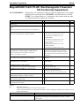
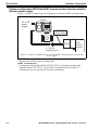
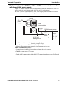
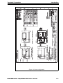
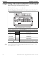
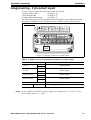
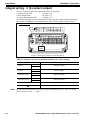
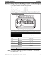
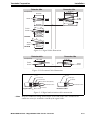
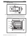
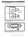
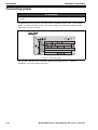
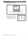
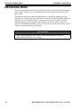
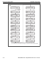
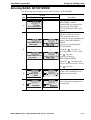
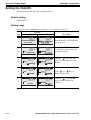
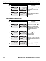
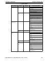
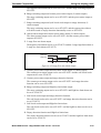
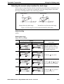
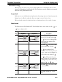
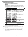
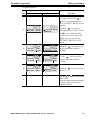
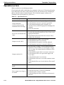
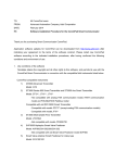
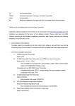
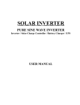
Installation
Yamatake Corporation
Integral wiring - 3 (2-contact output)
To wire a remote system, the following cables are required:
• Analog output cable
- see page 2-16
• Pulse output cable
- see page 2-17
• Contact input/output cable
- see page 2-17
The following pages provide information on selecting the correct cables and wiring
the system. A diagram of the terminal block for a remote system is shown below.
2-contact output
E
STATUS OUT 2 STATUS OUT 1
SB
+
+
P. OUT
POWER AC
X
Y
+
L
N
E
STATUS OUT 2 STATUS OUT 1
SB
+
+
P. OUT
POWER AC
X
Y
+
L
N
SA
C
I. OUT
+
-
SA
A
B
C
A
I. OUT
+
-
B
AC
POWER
Figure 2-6 Integral converter terminal block
Table 2-3 Remote converter terminal descriptions (2-contact output)
Symbol
I. OUT
P. OUT
STATUS OUT 1
STATUS OUT 2
E
Description
+
–
+
–
+
–
+
–
Analog output
Pulse output
Contact output 1
Contact output 2
Not used
Grounding (grounding resistance must be < 100 Ω)
~ Note
2-8
In case of DC24V and DC110V power supply, the symbol of the “L” and “N” of the
power supply become “+” and “–”.
Model MGG10C/14C - MagneW3000 FLEX+/PLUS+ Converter