1
Intel Architecture
Software Developer’s
Manual
Volume 2:
Instruction Set Reference
NOTE: The Intel Architecture Software Developer’s Manual consists of
three volumes: Basic Architecture, Order Number 243190; Instruction Set
Reference, Order Number 243191; and the System Programming Guide,
Order Number 243192.
Please refer to all three volumes when evaluating your design needs.
1999
Information in this document is provided in connection with Intel products. No license, express or implied, by estoppel
or otherwise, to any intellectual property rights is granted by this document. Except as provided in Intel’s Terms and
Conditions of Sale for such products, Intel assumes no liability whatsoever, and Intel disclaims any express or implied
warranty, relating to sale and/or use of Intel products including liability or warranties relating to fitness for a particular
purpose, merchantability, or infringement of any patent, copyright or other intellectual property right. Intel products are
not intended for use in medical, life saving, or life sustaining applications.
Intel may make changes to specifications and product descriptions at any time, without notice.
Designers must not rely on the absence or characteristics of any features or instructions marked “reserved” or
“undefined.” Intel reserves these for future definition and shall have no responsibility whatsoever for conflicts or
incompatibilities arising from future changes to them.
Intel’s Intel Architecture processors (e.g., Pentium®, Pentium® II, Pentium® III, and Pentium® Pro processors) may
contain design defects or errors known as errata which may cause the product to deviate from published
specifications. Current characterized errata are available on request.
Contact your local Intel sales office or your distributor to obtain the latest specifications and before placing your
product order.
Copies of documents which have an ordering number and are referenced in this document, or other Intel literature,
may be obtained by calling 1-800-548-4725, or by visiting Intel's literature center at http://www.intel.com.
COPYRIGHT © INTEL CORPORATION 1999
*THIRD-PARTY BRANDS AND NAMES ARE THE PROPERTY OF THEIR RESPECTIVE OWNERS.
TABLE OF CONTENTS
CHAPTER 1
ABOUT THIS MANUAL
1.1.
OVERVIEW OF THE INTEL ARCHITECTURE SOFTWARE DEVELOPER’S MANUAL,
1-1
VOLUME 2: INSTRUCTION SET REFERENCE
1.2.
OVERVIEW OF THE INTEL ARCHITECTURE SOFTWARE DEVELOPER’S MANUAL,
VOLUME 1: BASIC ARCHITECTURE
1-2
1.3.
OVERVIEW OF THE INTEL ARCHITECTURE SOFTWARE DEVELOPER’S MANUAL,
1-3
VOLUME 3: SYSTEM PROGRAMMING GUIDE
1.4.
NOTATIONAL CONVENTIONS . . . . . . . . . . . . . . . . . . . . . . . . . . . . . . . . . . . . . . . . 1-5
1.4.1.
Bit and Byte Order . . . . . . . . . . . . . . . . . . . . . . . . . . . . . . . . . . . . . . . . . . . . . . . . .1-5
1.4.2.
Reserved Bits and Software Compatibility . . . . . . . . . . . . . . . . . . . . . . . . . . . . . .1-6
1.4.3.
Instruction Operands . . . . . . . . . . . . . . . . . . . . . . . . . . . . . . . . . . . . . . . . . . . . . . .1-7
1.4.4.
Hexadecimal and Binary Numbers . . . . . . . . . . . . . . . . . . . . . . . . . . . . . . . . . . . .1-7
1.4.5.
Segmented Addressing . . . . . . . . . . . . . . . . . . . . . . . . . . . . . . . . . . . . . . . . . . . . .1-7
1.4.6.
Exceptions . . . . . . . . . . . . . . . . . . . . . . . . . . . . . . . . . . . . . . . . . . . . . . . . . . . . . . .1-8
1.5.
RELATED LITERATURE . . . . . . . . . . . . . . . . . . . . . . . . . . . . . . . . . . . . . . . . . . . . . 1-9
CHAPTER 2
INSTRUCTION FORMAT
2.1.
GENERAL INSTRUCTION FORMAT . . . . . . . . . . . . . . . . . . . . . . . . . . . . . . . . . . .
2.2.
INSTRUCTION PREFIXES . . . . . . . . . . . . . . . . . . . . . . . . . . . . . . . . . . . . . . . . . . .
2.3.
OPCODE . . . . . . . . . . . . . . . . . . . . . . . . . . . . . . . . . . . . . . . . . . . . . . . . . . . . . . . . .
2.4.
MODR/M AND SIB BYTES . . . . . . . . . . . . . . . . . . . . . . . . . . . . . . . . . . . . . . . . . . .
2.5.
DISPLACEMENT AND IMMEDIATE BYTES . . . . . . . . . . . . . . . . . . . . . . . . . . . . . .
2.6.
ADDRESSING-MODE ENCODING OF MODR/M AND SIB BYTES . . . . . . . . . . . .
2-1
2-1
2-2
2-2
2-3
2-3
CHAPTER 3
INSTRUCTION SET REFERENCE
3.1.
INTERPRETING THE INSTRUCTION REFERENCE PAGES . . . . . . . . . . . . . . . . 3-1
3.1.1.
Instruction Format . . . . . . . . . . . . . . . . . . . . . . . . . . . . . . . . . . . . . . . . . . . . . . . . .3-1
3.1.1.1.
Opcode Column . . . . . . . . . . . . . . . . . . . . . . . . . . . . . . . . . . . . . . . . . . . . . . . .3-2
3.1.1.2.
Instruction Column . . . . . . . . . . . . . . . . . . . . . . . . . . . . . . . . . . . . . . . . . . . . . .3-3
3.1.1.3.
Description Column . . . . . . . . . . . . . . . . . . . . . . . . . . . . . . . . . . . . . . . . . . . . .3-5
3.1.1.4.
Description . . . . . . . . . . . . . . . . . . . . . . . . . . . . . . . . . . . . . . . . . . . . . . . . . . . .3-5
3.1.2.
Operation. . . . . . . . . . . . . . . . . . . . . . . . . . . . . . . . . . . . . . . . . . . . . . . . . . . . . . . .3-6
3.1.3.
Intel C/C++ Compiler Intrinsics Equivalent . . . . . . . . . . . . . . . . . . . . . . . . . . . . . .3-9
3.1.3.1.
The Intrinsics API . . . . . . . . . . . . . . . . . . . . . . . . . . . . . . . . . . . . . . . . . . . . . . .3-9
3.1.3.2.
MMX™ Technology Intrinsics . . . . . . . . . . . . . . . . . . . . . . . . . . . . . . . . . . . . .3-10
3.1.3.3.
SIMD Floating-Point Intrinsics . . . . . . . . . . . . . . . . . . . . . . . . . . . . . . . . . . . .3-10
3.1.4.
Flags Affected . . . . . . . . . . . . . . . . . . . . . . . . . . . . . . . . . . . . . . . . . . . . . . . . . . .3-11
3.1.5.
FPU Flags Affected . . . . . . . . . . . . . . . . . . . . . . . . . . . . . . . . . . . . . . . . . . . . . . .3-12
3.1.6.
Protected Mode Exceptions. . . . . . . . . . . . . . . . . . . . . . . . . . . . . . . . . . . . . . . . .3-12
3.1.7.
Real-Address Mode Exceptions . . . . . . . . . . . . . . . . . . . . . . . . . . . . . . . . . . . . .3-12
3.1.8.
Virtual-8086 Mode Exceptions. . . . . . . . . . . . . . . . . . . . . . . . . . . . . . . . . . . . . . .3-13
3.1.9.
Floating-Point Exceptions . . . . . . . . . . . . . . . . . . . . . . . . . . . . . . . . . . . . . . . . . .3-14
3.1.10.
SIMD Floating-Point Exceptions - Streaming SIMD Extensions Only . . . . . . . . .3-14
iii
TABLE OF CONTENTS
3.2.
iv
INSTRUCTION REFERENCE . . . . . . . . . . . . . . . . . . . . . . . . . . . . . . . . . . . . . . . . 3-16
AAA—ASCII Adjust After Addition . . . . . . . . . . . . . . . . . . . . . . . . . . . . . . . . . . . . . . . .3-17
AAD—ASCII Adjust AX Before Division . . . . . . . . . . . . . . . . . . . . . . . . . . . . . . . . . . . .3-18
AAM—ASCII Adjust AX After Multiply . . . . . . . . . . . . . . . . . . . . . . . . . . . . . . . . . . . . .3-19
AAS—ASCII Adjust AL After Subtraction . . . . . . . . . . . . . . . . . . . . . . . . . . . . . . . . . . .3-20
ADC—Add with Carry. . . . . . . . . . . . . . . . . . . . . . . . . . . . . . . . . . . . . . . . . . . . . . . . . .3-21
ADD—Add . . . . . . . . . . . . . . . . . . . . . . . . . . . . . . . . . . . . . . . . . . . . . . . . . . . . . . . . . .3-23
ADDPS—Packed Single-FP Add . . . . . . . . . . . . . . . . . . . . . . . . . . . . . . . . . . . . . . . . .3-25
ADDSS—Scalar Single-FP Add . . . . . . . . . . . . . . . . . . . . . . . . . . . . . . . . . . . . . . . . . .3-27
AND—Logical AND . . . . . . . . . . . . . . . . . . . . . . . . . . . . . . . . . . . . . . . . . . . . . . . . . . .3-30
ANDNPS—Bit-wise Logical And Not For Single-FP. . . . . . . . . . . . . . . . . . . . . . . . . . .3-32
ANDPS—Bit-wise Logical And For Single FP . . . . . . . . . . . . . . . . . . . . . . . . . . . . . . .3-34
ARPL—Adjust RPL Field of Segment Selector . . . . . . . . . . . . . . . . . . . . . . . . . . . . . .3-36
BOUND—Check Array Index Against Bounds . . . . . . . . . . . . . . . . . . . . . . . . . . . . . . .3-38
BSF—Bit Scan Forward . . . . . . . . . . . . . . . . . . . . . . . . . . . . . . . . . . . . . . . . . . . . . . . .3-40
BSR—Bit Scan Reverse. . . . . . . . . . . . . . . . . . . . . . . . . . . . . . . . . . . . . . . . . . . . . . . .3-42
BSWAP—Byte Swap . . . . . . . . . . . . . . . . . . . . . . . . . . . . . . . . . . . . . . . . . . . . . . . . . .3-44
BT—Bit Test . . . . . . . . . . . . . . . . . . . . . . . . . . . . . . . . . . . . . . . . . . . . . . . . . . . . . . . . .3-45
BTC—Bit Test and Complement . . . . . . . . . . . . . . . . . . . . . . . . . . . . . . . . . . . . . . . . .3-47
BTR—Bit Test and Reset . . . . . . . . . . . . . . . . . . . . . . . . . . . . . . . . . . . . . . . . . . . . . . .3-49
BTS—Bit Test and Set . . . . . . . . . . . . . . . . . . . . . . . . . . . . . . . . . . . . . . . . . . . . . . . . .3-51
CALL—Call Procedure . . . . . . . . . . . . . . . . . . . . . . . . . . . . . . . . . . . . . . . . . . . . . . . . .3-53
CBW/CWDE—Convert Byte to Word/Convert Word to Doubleword . . . . . . . . . . . . . .3-64
CDQ—Convert Double to Quad . . . . . . . . . . . . . . . . . . . . . . . . . . . . . . . . . . . . . . . . . .3-65
CLC—Clear Carry Flag . . . . . . . . . . . . . . . . . . . . . . . . . . . . . . . . . . . . . . . . . . . . . . . .3-66
CLD—Clear Direction Flag. . . . . . . . . . . . . . . . . . . . . . . . . . . . . . . . . . . . . . . . . . . . . .3-67
CLI—Clear Interrupt Flag . . . . . . . . . . . . . . . . . . . . . . . . . . . . . . . . . . . . . . . . . . . . . . .3-68
CLTS—Clear Task-Switched Flag in CR0 . . . . . . . . . . . . . . . . . . . . . . . . . . . . . . . . . .3-70
CMC—Complement Carry Flag . . . . . . . . . . . . . . . . . . . . . . . . . . . . . . . . . . . . . . . . . .3-71
CMOVcc—Conditional Move . . . . . . . . . . . . . . . . . . . . . . . . . . . . . . . . . . . . . . . . . . . .3-72
CMP—Compare Two Operands . . . . . . . . . . . . . . . . . . . . . . . . . . . . . . . . . . . . . . . . .3-76
CMPPS—Packed Single-FP Compare . . . . . . . . . . . . . . . . . . . . . . . . . . . . . . . . . . . .3-78
CMPS/CMPSB/CMPSW/CMPSD—Compare String Operands. . . . . . . . . . . . . . . . . .3-87
CMPSS—Scalar Single-FP Compare . . . . . . . . . . . . . . . . . . . . . . . . . . . . . . . . . . . . .3-90
CMPXCHG—Compare and Exchange. . . . . . . . . . . . . . . . . . . . . . . . . . . . . . . . . . . .3-100
CMPXCHG8B—Compare and Exchange 8 Bytes . . . . . . . . . . . . . . . . . . . . . . . . . . .3-102
COMISS—Scalar Ordered Single-FP Compare and Set EFLAGS . . . . . . . . . . . . . .3-104
CPUID—CPU Identification . . . . . . . . . . . . . . . . . . . . . . . . . . . . . . . . . . . . . . . . . . . .3-111
CVTPI2PS—Packed Signed INT32 to Packed Single-FP Conversion . . . . . . . . . . .3-119
CVTPS2PI—Packed Single-FP to Packed INT32 Conversion. . . . . . . . . . . . . . . . . .3-123
CVTSI2SS—Scalar Signed INT32 to Single-FP Conversion . . . . . . . . . . . . . . . . . . .3-127
CVTSS2SI—Scalar Single-FP to Signed INT32 Conversion . . . . . . . . . . . . . . . . . . .3-130
CVTTPS2PI—Packed Single-FP to Packed INT32 Conversion (Truncate). . . . . . . .3-133
CVTTSS2SI—Scalar Single-FP to Signed INT32 Conversion (Truncate) . . . . . . . . .3-137
CWD/CDQ—Convert Word to Doubleword/Convert Doubleword
to Quadword. . . . . . . . . . . . . . . . . . . . . . . . . . . . . . . . . . . . . . . . . . . . . . . . . . . . . . . .3-141
CWDE—Convert Word to Doubleword . . . . . . . . . . . . . . . . . . . . . . . . . . . . . . . . . . .3-142
TABLE OF CONTENTS
DAA—Decimal Adjust AL after Addition . . . . . . . . . . . . . . . . . . . . . . . . . . . . . . . . . .
DAS—Decimal Adjust AL after Subtraction . . . . . . . . . . . . . . . . . . . . . . . . . . . . . . .
DEC—Decrement by 1 . . . . . . . . . . . . . . . . . . . . . . . . . . . . . . . . . . . . . . . . . . . . . . .
DIV—Unsigned Divide . . . . . . . . . . . . . . . . . . . . . . . . . . . . . . . . . . . . . . . . . . . . . . .
DIVPS—Packed Single-FP Divide . . . . . . . . . . . . . . . . . . . . . . . . . . . . . . . . . . . . . .
DIVSS—Scalar Single-FP Divide . . . . . . . . . . . . . . . . . . . . . . . . . . . . . . . . . . . . . . .
EMMS—Empty MMX™ State. . . . . . . . . . . . . . . . . . . . . . . . . . . . . . . . . . . . . . . . . .
ENTER—Make Stack Frame for Procedure Parameters . . . . . . . . . . . . . . . . . . . . .
F2XM1—Compute 2x–1 . . . . . . . . . . . . . . . . . . . . . . . . . . . . . . . . . . . . . . . . . . . . . .
FABS—Absolute Value . . . . . . . . . . . . . . . . . . . . . . . . . . . . . . . . . . . . . . . . . . . . . .
FADD/FADDP/FIADD—Add . . . . . . . . . . . . . . . . . . . . . . . . . . . . . . . . . . . . . . . . . . .
FBLD—Load Binary Coded Decimal . . . . . . . . . . . . . . . . . . . . . . . . . . . . . . . . . . . .
FBSTP—Store BCD Integer and Pop. . . . . . . . . . . . . . . . . . . . . . . . . . . . . . . . . . . .
FCHS—Change Sign . . . . . . . . . . . . . . . . . . . . . . . . . . . . . . . . . . . . . . . . . . . . . . . .
FCLEX/FNCLEX—Clear Exceptions . . . . . . . . . . . . . . . . . . . . . . . . . . . . . . . . . . . .
FCMOVcc—Floating-Point Conditional Move. . . . . . . . . . . . . . . . . . . . . . . . . . . . . .
FCOM/FCOMP/FCOMPP—Compare Real . . . . . . . . . . . . . . . . . . . . . . . . . . . . . . .
FCOMI/FCOMIP/ FUCOMI/FUCOMIP—Compare Real and Set EFLAGS . . . . . . .
FCOS—Cosine . . . . . . . . . . . . . . . . . . . . . . . . . . . . . . . . . . . . . . . . . . . . . . . . . . . . .
FDECSTP—Decrement Stack-Top Pointer . . . . . . . . . . . . . . . . . . . . . . . . . . . . . . .
FDIV/FDIVP/FIDIV—Divide . . . . . . . . . . . . . . . . . . . . . . . . . . . . . . . . . . . . . . . . . . .
FDIVR/FDIVRP/FIDIVR—Reverse Divide . . . . . . . . . . . . . . . . . . . . . . . . . . . . . . . .
FFREE—Free Floating-Point Register . . . . . . . . . . . . . . . . . . . . . . . . . . . . . . . . . . .
FICOM/FICOMP—Compare Integer. . . . . . . . . . . . . . . . . . . . . . . . . . . . . . . . . . . . .
FILD—Load Integer . . . . . . . . . . . . . . . . . . . . . . . . . . . . . . . . . . . . . . . . . . . . . . . . .
FINCSTP—Increment Stack-Top Pointer . . . . . . . . . . . . . . . . . . . . . . . . . . . . . . . . .
FINIT/FNINIT—Initialize Floating-Point Unit . . . . . . . . . . . . . . . . . . . . . . . . . . . . . . .
FIST/FISTP—Store Integer . . . . . . . . . . . . . . . . . . . . . . . . . . . . . . . . . . . . . . . . . . .
FLD—Load Real. . . . . . . . . . . . . . . . . . . . . . . . . . . . . . . . . . . . . . . . . . . . . . . . . . . .
FLD1/FLDL2T/FLDL2E/FLDPI/FLDLG2/FLDLN2/FLDZ—Load Constant . . . . . . . .
FLDCW—Load Control Word . . . . . . . . . . . . . . . . . . . . . . . . . . . . . . . . . . . . . . . . . .
FLDENV—Load FPU Environment. . . . . . . . . . . . . . . . . . . . . . . . . . . . . . . . . . . . . .
FMUL/FMULP/FIMUL—Multiply . . . . . . . . . . . . . . . . . . . . . . . . . . . . . . . . . . . . . . . .
FNOP—No Operation. . . . . . . . . . . . . . . . . . . . . . . . . . . . . . . . . . . . . . . . . . . . . . . .
FPATAN—Partial Arctangent . . . . . . . . . . . . . . . . . . . . . . . . . . . . . . . . . . . . . . . . . .
FPREM—Partial Remainder. . . . . . . . . . . . . . . . . . . . . . . . . . . . . . . . . . . . . . . . . . .
FPREM1—Partial Remainder. . . . . . . . . . . . . . . . . . . . . . . . . . . . . . . . . . . . . . . . . .
FPTAN—Partial Tangent . . . . . . . . . . . . . . . . . . . . . . . . . . . . . . . . . . . . . . . . . . . . .
FRNDINT—Round to Integer . . . . . . . . . . . . . . . . . . . . . . . . . . . . . . . . . . . . . . . . . .
FRSTOR—Restore FPU State . . . . . . . . . . . . . . . . . . . . . . . . . . . . . . . . . . . . . . . . .
FSAVE/FNSAVE—Store FPU State. . . . . . . . . . . . . . . . . . . . . . . . . . . . . . . . . . . . .
FSCALE—Scale . . . . . . . . . . . . . . . . . . . . . . . . . . . . . . . . . . . . . . . . . . . . . . . . . . . .
FSIN—Sine. . . . . . . . . . . . . . . . . . . . . . . . . . . . . . . . . . . . . . . . . . . . . . . . . . . . . . . .
FSINCOS—Sine and Cosine . . . . . . . . . . . . . . . . . . . . . . . . . . . . . . . . . . . . . . . . . .
FSQRT—Square Root . . . . . . . . . . . . . . . . . . . . . . . . . . . . . . . . . . . . . . . . . . . . . . .
FST/FSTP—Store Real . . . . . . . . . . . . . . . . . . . . . . . . . . . . . . . . . . . . . . . . . . . . . .
FSTCW/FNSTCW—Store Control Word . . . . . . . . . . . . . . . . . . . . . . . . . . . . . . . . .
3-143
3-145
3-146
3-148
3-151
3-154
3-156
3-158
3-161
3-163
3-165
3-169
3-171
3-174
3-176
3-178
3-180
3-183
3-186
3-188
3-189
3-193
3-197
3-198
3-200
3-202
3-203
3-205
3-208
3-210
3-212
3-214
3-216
3-220
3-221
3-223
3-226
3-229
3-231
3-232
3-235
3-238
3-240
3-242
3-244
3-246
3-249
v
TABLE OF CONTENTS
FSTENV/FNSTENV—Store FPU Environment . . . . . . . . . . . . . . . . . . . . . . . . . . . . .3-251
FSTSW/FNSTSW—Store Status Word . . . . . . . . . . . . . . . . . . . . . . . . . . . . . . . . . . .3-254
FSUB/FSUBP/FISUB—Subtract . . . . . . . . . . . . . . . . . . . . . . . . . . . . . . . . . . . . . . . .3-257
FSUBR/FSUBRP/FISUBR—Reverse Subtract . . . . . . . . . . . . . . . . . . . . . . . . . . . . .3-261
FTST—TEST . . . . . . . . . . . . . . . . . . . . . . . . . . . . . . . . . . . . . . . . . . . . . . . . . . . . . . .3-265
FUCOM/FUCOMP/FUCOMPP—Unordered Compare Real . . . . . . . . . . . . . . . . . . .3-267
FWAIT—Wait . . . . . . . . . . . . . . . . . . . . . . . . . . . . . . . . . . . . . . . . . . . . . . . . . . . . . . .3-270
FXAM—Examine . . . . . . . . . . . . . . . . . . . . . . . . . . . . . . . . . . . . . . . . . . . . . . . . . . . .3-271
FXCH—Exchange Register Contents . . . . . . . . . . . . . . . . . . . . . . . . . . . . . . . . . . . .3-273
FXRSTOR—Restore FP and MMX™ State and
Streaming SIMD Extension State. . . . . . . . . . . . . . . . . . . . . . . . . . . . . . . . . . . . . . . .3-275
FXSAVE—Store FP and MMX™ State and Streaming SIMD Extension State . . . . .3-279
FXTRACT—Extract Exponent and Significand . . . . . . . . . . . . . . . . . . . . . . . . . . . . .3-285
FYL2X—Compute y * log2x . . . . . . . . . . . . . . . . . . . . . . . . . . . . . . . . . . . . . . . . . . . .3-287
FYL2XP1—Compute y * log2(x +1) . . . . . . . . . . . . . . . . . . . . . . . . . . . . . . . . . . . . . .3-289
HLT—Halt. . . . . . . . . . . . . . . . . . . . . . . . . . . . . . . . . . . . . . . . . . . . . . . . . . . . . . . . . .3-291
IDIV—Signed Divide. . . . . . . . . . . . . . . . . . . . . . . . . . . . . . . . . . . . . . . . . . . . . . . . . .3-292
IMUL—Signed Multiply. . . . . . . . . . . . . . . . . . . . . . . . . . . . . . . . . . . . . . . . . . . . . . . .3-295
IN—Input from Port . . . . . . . . . . . . . . . . . . . . . . . . . . . . . . . . . . . . . . . . . . . . . . . . . .3-299
INC—Increment by 1 . . . . . . . . . . . . . . . . . . . . . . . . . . . . . . . . . . . . . . . . . . . . . . . . .3-301
INS/INSB/INSW/INSD—Input from Port to String . . . . . . . . . . . . . . . . . . . . . . . . . . .3-303
INT n/INTO/INT 3—Call to Interrupt Procedure . . . . . . . . . . . . . . . . . . . . . . . . . . . . .3-306
INVD—Invalidate Internal Caches . . . . . . . . . . . . . . . . . . . . . . . . . . . . . . . . . . . . . . .3-318
INVLPG—Invalidate TLB Entry . . . . . . . . . . . . . . . . . . . . . . . . . . . . . . . . . . . . . . . . .3-320
IRET/IRETD—Interrupt Return. . . . . . . . . . . . . . . . . . . . . . . . . . . . . . . . . . . . . . . . . .3-321
Jcc—Jump if Condition Is Met . . . . . . . . . . . . . . . . . . . . . . . . . . . . . . . . . . . . . . . . . .3-329
JMP—Jump . . . . . . . . . . . . . . . . . . . . . . . . . . . . . . . . . . . . . . . . . . . . . . . . . . . . . . . .3-333
LAHF—Load Status Flags into AH Register . . . . . . . . . . . . . . . . . . . . . . . . . . . . . . .3-341
LAR—Load Access Rights Byte. . . . . . . . . . . . . . . . . . . . . . . . . . . . . . . . . . . . . . . . .3-342
LDMXCSR—Load Streaming SIMD Extension Control/Status . . . . . . . . . . . . . . . . .3-345
LDS/LES/LFS/LGS/LSS—Load Far Pointer. . . . . . . . . . . . . . . . . . . . . . . . . . . . . . . .3-349
LEA—Load Effective Address . . . . . . . . . . . . . . . . . . . . . . . . . . . . . . . . . . . . . . . . . .3-353
LEAVE—High Level Procedure Exit. . . . . . . . . . . . . . . . . . . . . . . . . . . . . . . . . . . . . .3-355
LES—Load Full Pointer . . . . . . . . . . . . . . . . . . . . . . . . . . . . . . . . . . . . . . . . . . . . . . .3-357
LFS—Load Full Pointer . . . . . . . . . . . . . . . . . . . . . . . . . . . . . . . . . . . . . . . . . . . . . . .3-358
LGDT/LIDT—Load Global/Interrupt Descriptor Table Register . . . . . . . . . . . . . . . . .3-359
LGS—Load Full Pointer . . . . . . . . . . . . . . . . . . . . . . . . . . . . . . . . . . . . . . . . . . . . . . .3-361
LLDT—Load Local Descriptor Table Register . . . . . . . . . . . . . . . . . . . . . . . . . . . . . .3-362
LIDT—Load Interrupt Descriptor Table Register . . . . . . . . . . . . . . . . . . . . . . . . . . . .3-364
LMSW—Load Machine Status Word . . . . . . . . . . . . . . . . . . . . . . . . . . . . . . . . . . . . .3-365
LOCK—Assert LOCK# Signal Prefix . . . . . . . . . . . . . . . . . . . . . . . . . . . . . . . . . . . . .3-367
LODS/LODSB/LODSW/LODSD—Load String. . . . . . . . . . . . . . . . . . . . . . . . . . . . . .3-369
LOOP/LOOPcc—Loop According to ECX Counter . . . . . . . . . . . . . . . . . . . . . . . . . .3-372
LSL—Load Segment Limit . . . . . . . . . . . . . . . . . . . . . . . . . . . . . . . . . . . . . . . . . . . . .3-375
LSS—Load Full Pointer . . . . . . . . . . . . . . . . . . . . . . . . . . . . . . . . . . . . . . . . . . . . . . .3-379
LTR—Load Task Register . . . . . . . . . . . . . . . . . . . . . . . . . . . . . . . . . . . . . . . . . . . . .3-380
MASKMOVQ—Byte Mask Write . . . . . . . . . . . . . . . . . . . . . . . . . . . . . . . . . . . . . . . .3-382
vi
TABLE OF CONTENTS
MAXPS—Packed Single-FP Maximum . . . . . . . . . . . . . . . . . . . . . . . . . . . . . . . . . .
MAXSS—Scalar Single-FP Maximum . . . . . . . . . . . . . . . . . . . . . . . . . . . . . . . . . . .
MINPS—Packed Single-FP Minimum . . . . . . . . . . . . . . . . . . . . . . . . . . . . . . . . . . .
MINSS—Scalar Single-FP Minimum . . . . . . . . . . . . . . . . . . . . . . . . . . . . . . . . . . . .
MOV—Move . . . . . . . . . . . . . . . . . . . . . . . . . . . . . . . . . . . . . . . . . . . . . . . . . . . . . . .
MOV—Move to/from Control Registers . . . . . . . . . . . . . . . . . . . . . . . . . . . . . . . . . .
MOV—Move to/from Debug Registers . . . . . . . . . . . . . . . . . . . . . . . . . . . . . . . . . . .
MOVAPS—Move Aligned Four Packed Single-FP. . . . . . . . . . . . . . . . . . . . . . . . . .
MOVD—Move 32 Bits . . . . . . . . . . . . . . . . . . . . . . . . . . . . . . . . . . . . . . . . . . . . . . .
MOVHLPS— High to Low Packed Single-FP. . . . . . . . . . . . . . . . . . . . . . . . . . . . . .
MOVHPS—Move High Packed Single-FP . . . . . . . . . . . . . . . . . . . . . . . . . . . . . . . .
MOVLHPS—Move Low to High Packed Single-FP . . . . . . . . . . . . . . . . . . . . . . . . .
MOVLPS—Move Low Packed Single-FP . . . . . . . . . . . . . . . . . . . . . . . . . . . . . . . . .
MOVMSKPS—Move Mask To Integer . . . . . . . . . . . . . . . . . . . . . . . . . . . . . . . . . . .
MOVNTPS—Move Aligned Four Packed Single-FP Non Temporal. . . . . . . . . . . . .
MOVNTQ—Move 64 Bits Non Temporal . . . . . . . . . . . . . . . . . . . . . . . . . . . . . . . . .
MOVQ—Move 64 Bits . . . . . . . . . . . . . . . . . . . . . . . . . . . . . . . . . . . . . . . . . . . . . . .
MOVS/MOVSB/MOVSW/MOVSD—Move Data from String to String . . . . . . . . . . .
MOVSS—Move Scalar Single-FP . . . . . . . . . . . . . . . . . . . . . . . . . . . . . . . . . . . . . .
MOVSX—Move with Sign-Extension . . . . . . . . . . . . . . . . . . . . . . . . . . . . . . . . . . . .
MOVUPS—Move Unaligned Four Packed Single-FP . . . . . . . . . . . . . . . . . . . . . . .
MOVZX—Move with Zero-Extend . . . . . . . . . . . . . . . . . . . . . . . . . . . . . . . . . . . . . .
MUL—Unsigned Multiply . . . . . . . . . . . . . . . . . . . . . . . . . . . . . . . . . . . . . . . . . . . . .
MULPS—Packed Single-FP Multiply . . . . . . . . . . . . . . . . . . . . . . . . . . . . . . . . . . . .
MULSS—Scalar Single-FP Multiply . . . . . . . . . . . . . . . . . . . . . . . . . . . . . . . . . . . . .
NEG—Two's Complement Negation . . . . . . . . . . . . . . . . . . . . . . . . . . . . . . . . . . . .
NOP—No Operation. . . . . . . . . . . . . . . . . . . . . . . . . . . . . . . . . . . . . . . . . . . . . . . . .
NOT—One's Complement Negation . . . . . . . . . . . . . . . . . . . . . . . . . . . . . . . . . . . .
OR—Logical Inclusive OR . . . . . . . . . . . . . . . . . . . . . . . . . . . . . . . . . . . . . . . . . . . .
ORPS—Bit-wise Logical OR for Single-FP Data . . . . . . . . . . . . . . . . . . . . . . . . . . .
OUT—Output to Port . . . . . . . . . . . . . . . . . . . . . . . . . . . . . . . . . . . . . . . . . . . . . . . .
OUTS/OUTSB/OUTSW/OUTSD—Output String to Port . . . . . . . . . . . . . . . . . . . . .
PACKSSWB/PACKSSDW—Pack with Signed Saturation . . . . . . . . . . . . . . . . . . . .
PACKUSWB—Pack with Unsigned Saturation. . . . . . . . . . . . . . . . . . . . . . . . . . . . .
PADDB/PADDW/PADDD—Packed Add . . . . . . . . . . . . . . . . . . . . . . . . . . . . . . . . .
PADDSB/PADDSW—Packed Add with Saturation . . . . . . . . . . . . . . . . . . . . . . . . .
PADDUSB/PADDUSW—Packed Add Unsigned with Saturation . . . . . . . . . . . . . . .
PAND—Logical AND . . . . . . . . . . . . . . . . . . . . . . . . . . . . . . . . . . . . . . . . . . . . . . . .
PANDN—Logical AND NOT . . . . . . . . . . . . . . . . . . . . . . . . . . . . . . . . . . . . . . . . . . .
PAVGB/PAVGW—Packed Average . . . . . . . . . . . . . . . . . . . . . . . . . . . . . . . . . . . . .
PCMPEQB/PCMPEQW/PCMPEQD—Packed Compare for Equal . . . . . . . . . . . . .
PCMPGTB/PCMPGTW/PCMPGTD—Packed Compare for Greater Than . . . . . . .
PEXTRW—Extract Word . . . . . . . . . . . . . . . . . . . . . . . . . . . . . . . . . . . . . . . . . . . . .
PINSRW—Insert Word . . . . . . . . . . . . . . . . . . . . . . . . . . . . . . . . . . . . . . . . . . . . . . .
PMADDWD—Packed Multiply and Add . . . . . . . . . . . . . . . . . . . . . . . . . . . . . . . . . .
PMAXSW—Packed Signed Integer Word Maximum . . . . . . . . . . . . . . . . . . . . . . . .
PMAXUB—Packed Unsigned Integer Byte Maximum . . . . . . . . . . . . . . . . . . . . . . .
3-386
3-390
3-394
3-398
3-402
3-407
3-409
3-411
3-414
3-417
3-419
3-422
3-424
3-427
3-429
3-431
3-433
3-435
3-438
3-441
3-443
3-446
3-448
3-450
3-452
3-454
3-456
3-457
3-459
3-461
3-463
3-465
3-469
3-472
3-475
3-479
3-482
3-485
3-487
3-489
3-493
3-497
3-501
3-503
3-505
3-508
3-511
vii
TABLE OF CONTENTS
PMINSW—Packed Signed Integer Word Minimum . . . . . . . . . . . . . . . . . . . . . . . . . .3-514
PMINUB—Packed Unsigned Integer Byte Minimum . . . . . . . . . . . . . . . . . . . . . . . . .3-517
PMOVMSKB—Move Byte Mask To Integer . . . . . . . . . . . . . . . . . . . . . . . . . . . . . . . .3-520
PMULHUW—Packed Multiply High Unsigned . . . . . . . . . . . . . . . . . . . . . . . . . . . . . .3-522
PMULHW—Packed Multiply High . . . . . . . . . . . . . . . . . . . . . . . . . . . . . . . . . . . . . . .3-525
PMULLW—Packed Multiply Low . . . . . . . . . . . . . . . . . . . . . . . . . . . . . . . . . . . . . . . .3-528
POP—Pop a Value from the Stack . . . . . . . . . . . . . . . . . . . . . . . . . . . . . . . . . . . . . .3-531
POPA/POPAD—Pop All General-Purpose Registers . . . . . . . . . . . . . . . . . . . . . . . .3-536
POPF/POPFD—Pop Stack into EFLAGS Register . . . . . . . . . . . . . . . . . . . . . . . . . .3-538
POR—Bitwise Logical OR . . . . . . . . . . . . . . . . . . . . . . . . . . . . . . . . . . . . . . . . . . . . .3-541
PREFETCH—Prefetch . . . . . . . . . . . . . . . . . . . . . . . . . . . . . . . . . . . . . . . . . . . . . . .3-543
PSADBW—Packed Sum of Absolute Differences . . . . . . . . . . . . . . . . . . . . . . . . . . .3-545
PSHUFW—Packed Shuffle Word . . . . . . . . . . . . . . . . . . . . . . . . . . . . . . . . . . . . . . .3-548
PSLLW/PSLLD/PSLLQ—Packed Shift Left Logical . . . . . . . . . . . . . . . . . . . . . . . . . .3-550
PSRAW/PSRAD—Packed Shift Right Arithmetic. . . . . . . . . . . . . . . . . . . . . . . . . . . .3-555
PSRLW/PSRLD/PSRLQ—Packed Shift Right Logical. . . . . . . . . . . . . . . . . . . . . . . .3-558
PSUBB/PSUBW/PSUBD—Packed Subtract . . . . . . . . . . . . . . . . . . . . . . . . . . . . . . .3-563
PSUBSB/PSUBSW—Packed Subtract with Saturation . . . . . . . . . . . . . . . . . . . . . . .3-567
PSUBUSB/PSUBUSW—Packed Subtract Unsigned with Saturation . . . . . . . . . . . .3-570
PUNPCKHBW/PUNPCKHWD/PUNPCKHDQ—Unpack High Packed Data . . . . . . .3-573
PUNPCKLBW/PUNPCKLWD/PUNPCKLDQ—Unpack Low Packed Data . . . . . . . .3-577
PUSH—Push Word or Doubleword Onto the Stack. . . . . . . . . . . . . . . . . . . . . . . . . .3-581
PUSHA/PUSHAD—Push All General-Purpose Registers . . . . . . . . . . . . . . . . . . . . .3-584
PUSHF/PUSHFD—Push EFLAGS Register onto the Stack . . . . . . . . . . . . . . . . . . .3-587
PXOR—Logical Exclusive OR . . . . . . . . . . . . . . . . . . . . . . . . . . . . . . . . . . . . . . . . . .3-589
RCL/RCR/ROL/ROR-—Rotate. . . . . . . . . . . . . . . . . . . . . . . . . . . . . . . . . . . . . . . . . .3-591
RCPPS—Packed Single-FP Reciprocal . . . . . . . . . . . . . . . . . . . . . . . . . . . . . . . . . .3-596
RCPSS—Scalar Single-FP Reciprocal . . . . . . . . . . . . . . . . . . . . . . . . . . . . . . . . . . .3-598
RDMSR—Read from Model Specific Register . . . . . . . . . . . . . . . . . . . . . . . . . . . . . .3-600
RDPMC—Read Performance-Monitoring Counters. . . . . . . . . . . . . . . . . . . . . . . . . .3-602
RDTSC—Read Time-Stamp Counter . . . . . . . . . . . . . . . . . . . . . . . . . . . . . . . . . . . .3-604
REP/REPE/REPZ/REPNE /REPNZ—Repeat String Operation Prefix . . . . . . . . . . .3-605
RET—Return from Procedure . . . . . . . . . . . . . . . . . . . . . . . . . . . . . . . . . . . . . . . . . .3-608
ROL/ROR—Rotate. . . . . . . . . . . . . . . . . . . . . . . . . . . . . . . . . . . . . . . . . . . . . . . . . . .3-615
RSM—Resume from System Management Mode . . . . . . . . . . . . . . . . . . . . . . . . . . .3-616
RSQRTPS—Packed Single-FP Square Root Reciprocal . . . . . . . . . . . . . . . . . . . . .3-617
RSQRTSS—Scalar Single-FP Square Root Reciprocal . . . . . . . . . . . . . . . . . . . . . .3-619
SAHF—Store AH into Flags . . . . . . . . . . . . . . . . . . . . . . . . . . . . . . . . . . . . . . . . . . . .3-621
SAL/SAR/SHL/SHR—Shift. . . . . . . . . . . . . . . . . . . . . . . . . . . . . . . . . . . . . . . . . . . . .3-622
SBB—Integer Subtraction with Borrow . . . . . . . . . . . . . . . . . . . . . . . . . . . . . . . . . . .3-627
SCAS/SCASB/SCASW/SCASD—Scan String . . . . . . . . . . . . . . . . . . . . . . . . . . . . .3-629
SETcc—Set Byte on Condition . . . . . . . . . . . . . . . . . . . . . . . . . . . . . . . . . . . . . . . . .3-632
SFENCE—Store Fence . . . . . . . . . . . . . . . . . . . . . . . . . . . . . . . . . . . . . . . . . . . . . . .3-634
SGDT/SIDT—Store Global/Interrupt Descriptor Table Register . . . . . . . . . . . . . . . .3-636
SHL/SHR—Shift Instructions . . . . . . . . . . . . . . . . . . . . . . . . . . . . . . . . . . . . . . . . . . .3-639
SHLD—Double Precision Shift Left . . . . . . . . . . . . . . . . . . . . . . . . . . . . . . . . . . . . . .3-640
SHRD—Double Precision Shift Right. . . . . . . . . . . . . . . . . . . . . . . . . . . . . . . . . . . . .3-643
viii
TABLE OF CONTENTS
SHUFPS—Shuffle Single-FP . . . . . . . . . . . . . . . . . . . . . . . . . . . . . . . . . . . . . . . . . .
SIDT—Store Interrupt Descriptor Table Register . . . . . . . . . . . . . . . . . . . . . . . . . . .
SLDT—Store Local Descriptor Table Register . . . . . . . . . . . . . . . . . . . . . . . . . . . . .
SMSW—Store Machine Status Word . . . . . . . . . . . . . . . . . . . . . . . . . . . . . . . . . . . .
SQRTPS—Packed Single-FP Square Root . . . . . . . . . . . . . . . . . . . . . . . . . . . . . .
SQRTSS—Scalar Single-FP Square Root . . . . . . . . . . . . . . . . . . . . . . . . . . . . . . . .
STC—Set Carry Flag . . . . . . . . . . . . . . . . . . . . . . . . . . . . . . . . . . . . . . . . . . . . . . . .
STD—Set Direction Flag . . . . . . . . . . . . . . . . . . . . . . . . . . . . . . . . . . . . . . . . . . . . .
STI—Set Interrupt Flag. . . . . . . . . . . . . . . . . . . . . . . . . . . . . . . . . . . . . . . . . . . . . . .
STMXCSR—Store Streaming SIMD Extension Control/Status . . . . . . . . . . . . . . . .
STOS/STOSB/STOSW/STOSD—Store String. . . . . . . . . . . . . . . . . . . . . . . . . . . . .
STR—Store Task Register . . . . . . . . . . . . . . . . . . . . . . . . . . . . . . . . . . . . . . . . . . . .
SUB—Subtract . . . . . . . . . . . . . . . . . . . . . . . . . . . . . . . . . . . . . . . . . . . . . . . . . . . . .
SUBPS—Packed Single-FP Subtract. . . . . . . . . . . . . . . . . . . . . . . . . . . . . . . . . . . .
SUBSS—Scalar Single-FP Subtract. . . . . . . . . . . . . . . . . . . . . . . . . . . . . . . . . . . . .
SYSENTER—Fast Transition to System Call Entry Point . . . . . . . . . . . . . . . . . . . .
SYSEXIT—Fast Transition from System Call Entry Point . . . . . . . . . . . . . . . . . . . .
TEST—Logical Compare . . . . . . . . . . . . . . . . . . . . . . . . . . . . . . . . . . . . . . . . . . . . .
UCOMISS—Unordered Scalar Single-FP compare and set EFLAGS . . . . . . . . . . .
UD2—Undefined Instruction. . . . . . . . . . . . . . . . . . . . . . . . . . . . . . . . . . . . . . . . . . .
UNPCKHPS—Unpack High Packed Single-FP Data . . . . . . . . . . . . . . . . . . . . . . . .
UNPCKLPS—Unpack Low Packed Single-FP Data . . . . . . . . . . . . . . . . . . . . . . . .
VERR/VERW—Verify a Segment for Reading or Writing. . . . . . . . . . . . . . . . . . . . .
WAIT/FWAIT—Wait . . . . . . . . . . . . . . . . . . . . . . . . . . . . . . . . . . . . . . . . . . . . . . . . .
WBINVD—Write Back and Invalidate Cache . . . . . . . . . . . . . . . . . . . . . . . . . . . . . .
WRMSR—Write to Model Specific Register . . . . . . . . . . . . . . . . . . . . . . . . . . . . . . .
XADD—Exchange and Add . . . . . . . . . . . . . . . . . . . . . . . . . . . . . . . . . . . . . . . . . . .
XCHG—Exchange Register/Memory with Register . . . . . . . . . . . . . . . . . . . . . . . . .
XLAT/XLATB—Table Look-up Translation. . . . . . . . . . . . . . . . . . . . . . . . . . . . . . . .
XOR—Logical Exclusive OR . . . . . . . . . . . . . . . . . . . . . . . . . . . . . . . . . . . . . . . . . .
XORPS—Bit-wise Logical Xor for Single-FP Data . . . . . . . . . . . . . . . . . . . . . . . . . .
3-646
3-651
3-652
3-654
3-656
3-659
3-662
3-663
3-664
3-666
3-668
3-671
3-673
3-675
3-678
3-681
3-685
3-688
3-690
3-697
3-698
3-701
3-704
3-707
3-708
3-710
3-712
3-714
3-716
3-718
3-720
APPENDIX A
OPCODE MAP
A.1.
KEY TO ABBREVIATIONS . . . . . . . . . . . . . . . . . . . . . . . . . . . . . . . . . . . . . . . . . . . A-1
A.1.1.
Codes for Addressing Method . . . . . . . . . . . . . . . . . . . . . . . . . . . . . . . . . . . . . . . A-1
A.1.2.
Codes for Operand Type . . . . . . . . . . . . . . . . . . . . . . . . . . . . . . . . . . . . . . . . . . . A-3
A.1.3.
Register Codes . . . . . . . . . . . . . . . . . . . . . . . . . . . . . . . . . . . . . . . . . . . . . . . . . . A-3
A.2.
OPCODE LOOK-UP EXAMPLES . . . . . . . . . . . . . . . . . . . . . . . . . . . . . . . . . . . . . . A-3
A.2.1.
One-Byte Opcode Instructions. . . . . . . . . . . . . . . . . . . . . . . . . . . . . . . . . . . . . . . A-4
A.2.2.
Two-Byte Opcode Instructions. . . . . . . . . . . . . . . . . . . . . . . . . . . . . . . . . . . . . . . A-4
A.2.3.
Opcode Map Shading . . . . . . . . . . . . . . . . . . . . . . . . . . . . . . . . . . . . . . . . . . . . . A-5
A.2.4.
Opcode Map Notes . . . . . . . . . . . . . . . . . . . . . . . . . . . . . . . . . . . . . . . . . . . . . . . A-5
A.2.5.
Opcode Extensions For One- And Two-byte Opcodes . . . . . . . . . . . . . . . . . . . A-10
A.2.6.
Escape Opcode Instructions . . . . . . . . . . . . . . . . . . . . . . . . . . . . . . . . . . . . . . . A-12
A.2.6.1.
Opcodes with ModR/M Bytes in the 00H through BFH Range . . . . . . . . . . . A-12
A.2.6.2.
Opcodes with ModR/M Bytes outside the 00H through BFH Range. . . . . . . A-12
A.2.6.3.
Escape Opcodes with D8 as First Byte. . . . . . . . . . . . . . . . . . . . . . . . . . . . . A-12
A.2.6.4.
Escape Opcodes with D9 as First Byte. . . . . . . . . . . . . . . . . . . . . . . . . . . . . A-14
ix
TABLE OF CONTENTS
A.2.6.5.
A.2.6.6.
A.2.6.7.
A.2.6.8.
A.2.6.9.
A.2.6.10.
Escape Opcodes with DA as First Byte
Escape Opcodes with DB as First Byte
Escape Opcodes with DC as First Byte
Escape Opcodes with DD as First Byte
Escape Opcodes with DE as First Byte
Escape Opcodes with DF As First Byte
............................
............................
............................
............................
............................
............................
A-15
A-16
A-18
A-19
A-21
A-22
APPENDIX B
INSTRUCTION FORMATS AND ENCODINGS
B.1.
MACHINE INSTRUCTION FORMAT . . . . . . . . . . . . . . . . . . . . . . . . . . . . . . . . . . . . B-1
B.1.1.
Reg Field (reg). . . . . . . . . . . . . . . . . . . . . . . . . . . . . . . . . . . . . . . . . . . . . . . . . . . B-2
B.1.2.
Encoding of Operand Size Bit (w) . . . . . . . . . . . . . . . . . . . . . . . . . . . . . . . . . . . . B-3
B.1.3.
Sign Extend (s) Bit. . . . . . . . . . . . . . . . . . . . . . . . . . . . . . . . . . . . . . . . . . . . . . . . B-3
B.1.4.
Segment Register Field (sreg). . . . . . . . . . . . . . . . . . . . . . . . . . . . . . . . . . . . . . . B-4
B.1.5.
Special-Purpose Register (eee) Field . . . . . . . . . . . . . . . . . . . . . . . . . . . . . . . . . B-4
B.1.6.
Condition Test Field (tttn) . . . . . . . . . . . . . . . . . . . . . . . . . . . . . . . . . . . . . . . . . . B-5
B.1.7.
Direction (d) Bit . . . . . . . . . . . . . . . . . . . . . . . . . . . . . . . . . . . . . . . . . . . . . . . . . . B-5
B.2.
INTEGER INSTRUCTION FORMATS AND ENCODINGS . . . . . . . . . . . . . . . . . . . B-6
B.3.
MMX™ INSTRUCTION FORMATS AND ENCODINGS . . . . . . . . . . . . . . . . . . . . B-19
B.3.1.
Granularity Field (gg). . . . . . . . . . . . . . . . . . . . . . . . . . . . . . . . . . . . . . . . . . . . . B-19
B.3.2.
MMX™ and General-Purpose Register Fields
(mmxreg and reg) . . . . . . . . . . . . . . . . . . . . . . . . . . . . . . . . . . . . . . . . . . . . . . . B-19
B.3.3.
MMX™ Instruction Formats and Encodings Table . . . . . . . . . . . . . . . . . . . . . . B-20
B.4.
STREAMING SIMD EXTENSION FORMATS AND ENCODINGS TABLE . . . . . . B-24
B.4.1.
Instruction Prefixes . . . . . . . . . . . . . . . . . . . . . . . . . . . . . . . . . . . . . . . . . . . . . . B-24
B.4.2.
Notations . . . . . . . . . . . . . . . . . . . . . . . . . . . . . . . . . . . . . . . . . . . . . . . . . . . . . . B-26
B.4.3.
Formats and Encodings. . . . . . . . . . . . . . . . . . . . . . . . . . . . . . . . . . . . . . . . . . . B-27
B.5.
FLOATING-POINT INSTRUCTION FORMATS AND ENCODINGS . . . . . . . . . . . B-36
APPENDIX C
COMPILER INTRINSICS AND FUNCTIONAL EQUIVALENTS
C.1.
SIMPLE INTRINSICS. . . . . . . . . . . . . . . . . . . . . . . . . . . . . . . . . . . . . . . . . . . . . . . . C-2
C.2.
COMPOSITE INTRINSICS . . . . . . . . . . . . . . . . . . . . . . . . . . . . . . . . . . . . . . . . . . C-11
x
TABLE OF FIGURES
Figure 1-1.
Figure 2-1.
Figure 3-1.
Figure 3-2.
Figure 3-3.
Figure 3-4.
Figure 3-5.
Figure 3-6.
Figure 3-7.
Figure 3-8.
Figure 3-9.
Figure 3-10.
Figure 3-11.
Figure 3-12.
Figure 3-13.
Figure 3-14.
Figure 3-15.
Figure 3-16.
Figure 3-17.
Figure 3-18.
Figure 3-19.
Figure 3-20.
Figure 3-21.
Figure 3-22.
Figure 3-23.
Figure 3-24.
Figure 3-25.
Figure 3-26.
Figure 3-27.
Figure 3-28.
Figure 3-29.
Figure 3-30.
Figure 3-31.
Figure 3-32.
Figure 3-33.
Figure 3-34.
Figure 3-35.
Figure 3-36.
Figure 3-37.
Figure 3-38.
Figure 3-39.
Figure 3-40.
Figure 3-41.
Figure 3-42.
Figure 3-43.
Figure 3-44.
Figure 3-45.
Figure 3-46.
Figure 3-47.
Bit and Byte Order . . . . . . . . . . . . . . . . . . . . . . . . . . . . . . . . . . . . . . . . . . . . . .1-6
Intel Architecture Instruction Format. . . . . . . . . . . . . . . . . . . . . . . . . . . . . . . . .2-1
Bit Offset for BIT[EAX,21] . . . . . . . . . . . . . . . . . . . . . . . . . . . . . . . . . . . . . . . . .3-8
Memory Bit Indexing . . . . . . . . . . . . . . . . . . . . . . . . . . . . . . . . . . . . . . . . . . . .3-12
Operation of the ADDPS Instruction . . . . . . . . . . . . . . . . . . . . . . . . . . . . . . . .3-25
Operation of the ADDSS Instruction . . . . . . . . . . . . . . . . . . . . . . . . . . . . . . . .3-27
Operation of the ANDNPS Instruction . . . . . . . . . . . . . . . . . . . . . . . . . . . . . .3-32
Operation of the ANDPS Instruction . . . . . . . . . . . . . . . . . . . . . . . . . . . . . . . .3-34
Operation of the CMPPS (Imm8=0) Instruction . . . . . . . . . . . . . . . . . . . . . . .3-78
Operation of the CMPPS (Imm8=1) Instruction . . . . . . . . . . . . . . . . . . . . . . .3-78
Operation of the CMPPS (Imm8=2) Instruction . . . . . . . . . . . . . . . . . . . . . . .3-79
Operation of the CMPPS (Imm8=3) Instruction . . . . . . . . . . . . . . . . . . . . . . .3-79
Operation of the CMPPS (Imm8=4) Instruction . . . . . . . . . . . . . . . . . . . . . . .3-80
Operation of the CMPPS (Imm8=5) Instruction . . . . . . . . . . . . . . . . . . . . . . .3-80
Operation of the CMPPS (Imm8=6) Instruction . . . . . . . . . . . . . . . . . . . . . . .3-81
Operation of the CMPPS (Imm8=7) Instruction . . . . . . . . . . . . . . . . . . . . . . .3-81
Operation of the CMPSS (Imm8=0) Instruction . . . . . . . . . . . . . . . . . . . . . . .3-92
Operation of the CMPSS (Imm8=1) Instruction . . . . . . . . . . . . . . . . . . . . . . .3-92
Operation of the CMPSS (Imm8=2) Instruction . . . . . . . . . . . . . . . . . . . . . . .3-93
Operation of the CMPSS (Imm8=3) Instruction . . . . . . . . . . . . . . . . . . . . . . .3-93
Operation of the CMPSS (Imm8=4) Instruction . . . . . . . . . . . . . . . . . . . . . . .3-94
Operation of the CMPSS (Imm8=5) Instruction . . . . . . . . . . . . . . . . . . . . . . .3-94
Operation of the CMPSS (Imm8=6) Instruction . . . . . . . . . . . . . . . . . . . . . . .3-95
Operation of the CMPSS (Imm8=7) Instruction . . . . . . . . . . . . . . . . . . . . . . .3-95
Operation of the COMISS Instruction, Condition One . . . . . . . . . . . . . . . . .3-104
Operation of the COMISS Instruction, Condition Two . . . . . . . . . . . . . . . . .3-105
Operation of the COMISS Instruction, Condition Three . . . . . . . . . . . . . . . .3-105
Operation of the COMISS Instruction, Condition Four . . . . . . . . . . . . . . . . .3-106
Version and Feature Information in Registers EAX and EDX. . . . . . . . . . . .3-112
Operation of the CVTPI2PS Instruction . . . . . . . . . . . . . . . . . . . . . . . . . . . .3-119
Operation of the CVTPS2PI Instruction . . . . . . . . . . . . . . . . . . . . . . . . . . . .3-123
Operation of the CVTSI2SS Instruction . . . . . . . . . . . . . . . . . . . . . . . . . . . .3-127
Operation of the CVTSS2SI Instruction . . . . . . . . . . . . . . . . . . . . . . . . . . . .3-130
Operation of the CVTTPS2PI Instruction . . . . . . . . . . . . . . . . . . . . . . . . . . .3-133
Operation of the CVTTSS2SI Instruction . . . . . . . . . . . . . . . . . . . . . . . . . . .3-137
Operation of the DIVPS Instruction. . . . . . . . . . . . . . . . . . . . . . . . . . . . . . . .3-151
Operation of the DIVSS Instruction. . . . . . . . . . . . . . . . . . . . . . . . . . . . . . . .3-154
Operation of the MAXPS Instruction. . . . . . . . . . . . . . . . . . . . . . . . . . . . . . .3-386
Operation of the MAXSS Instruction. . . . . . . . . . . . . . . . . . . . . . . . . . . . . . .3-390
Operation of the MINPS Instruction . . . . . . . . . . . . . . . . . . . . . . . . . . . . . . .3-394
Operation of the MINSS Instruction . . . . . . . . . . . . . . . . . . . . . . . . . . . . . . .3-398
Operation of the MOVAPS Instruction . . . . . . . . . . . . . . . . . . . . . . . . . . . . .3-411
Operation of the MOVD Instruction. . . . . . . . . . . . . . . . . . . . . . . . . . . . . . . .3-414
Operation of the MOVHLPS Instruction . . . . . . . . . . . . . . . . . . . . . . . . . . . .3-417
Operation of the MOVHPS Instruction . . . . . . . . . . . . . . . . . . . . . . . . . . . . .3-419
Operation of the MOVLHPS Instruction . . . . . . . . . . . . . . . . . . . . . . . . . . . .3-422
Operation of the MOVLPS Instruction . . . . . . . . . . . . . . . . . . . . . . . . . . . . .3-424
Operation of the MOVMSKPS Instruction. . . . . . . . . . . . . . . . . . . . . . . . . . .3-427
Operation of the MOVQ Instructions. . . . . . . . . . . . . . . . . . . . . . . . . . . . . . .3-433
xi
TABLE OF FIGURES
Figure 3-48.
Figure 3-49.
Figure 3-50.
Figure 3-51.
Figure 3-52.
Figure 3-53.
Figure 3-54.
Figure 3-55.
Figure 3-56.
Figure 3-57.
Figure 3-58.
Figure 3-59.
Figure 3-60.
Figure 3-61.
Figure 3-62.
Figure 3-63.
Figure 3-64.
Figure 3-65.
Figure 3-66.
Figure 3-67.
Figure 3-68.
Figure 3-69.
Figure 3-70.
Figure 3-71.
Figure 3-72.
Figure 3-73.
Figure 3-74.
Figure 3-75.
Figure 3-76.
Figure 3-77.
Figure 3-78.
Figure 3-79.
Figure 3-80.
Figure 3-81.
Figure 3-82.
Figure 3-83.
Figure 3-84.
Figure 3-85.
Figure 3-86.
Figure 3-87.
Figure 3-88.
Figure 3-89.
Figure 3-90.
Figure 3-91.
Figure 3-92.
Figure 3-93.
Figure 3-94.
Figure 3-95.
Figure 3-96.
Figure 3-97.
xii
Operation of the MOVSS Instruction . . . . . . . . . . . . . . . . . . . . . . . . . . . . . .3-438
Operation of the MOVUPS Instruction . . . . . . . . . . . . . . . . . . . . . . . . . . . . .3-443
Operation of the MULPS Instruction . . . . . . . . . . . . . . . . . . . . . . . . . . . . . . .3-450
Operation of the MULSS Instruction . . . . . . . . . . . . . . . . . . . . . . . . . . . . . . .3-452
Operation of the ORPS Instruction . . . . . . . . . . . . . . . . . . . . . . . . . . . . . . . .3-461
Operation of the PACKSSDW Instruction. . . . . . . . . . . . . . . . . . . . . . . . . . .3-469
Operation of the PACKUSWB Instruction. . . . . . . . . . . . . . . . . . . . . . . . . . .3-472
Operation of the PADDW Instruction . . . . . . . . . . . . . . . . . . . . . . . . . . . . . .3-475
Operation of the PADDSW Instruction . . . . . . . . . . . . . . . . . . . . . . . . . . . . .3-479
Operation of the PADDUSB Instruction . . . . . . . . . . . . . . . . . . . . . . . . . . . .3-482
Operation of the PAND Instruction . . . . . . . . . . . . . . . . . . . . . . . . . . . . . . . .3-485
Operation of the PANDN Instruction. . . . . . . . . . . . . . . . . . . . . . . . . . . . . . .3-487
Operation of the PAVGB/PAVGW Instruction. . . . . . . . . . . . . . . . . . . . . . . .3-489
Operation of the PCMPEQW Instruction . . . . . . . . . . . . . . . . . . . . . . . . . . .3-493
Operation of the PCMPGTW Instruction. . . . . . . . . . . . . . . . . . . . . . . . . . . .3-497
Operation of the PEXTRW Instruction . . . . . . . . . . . . . . . . . . . . . . . . . . . . .3-501
Operation of the PINSRW Instruction . . . . . . . . . . . . . . . . . . . . . . . . . . . . . .3-503
Operation of the PMADDWD Instruction . . . . . . . . . . . . . . . . . . . . . . . . . . .3-505
Operation of the PMAXSW Instruction . . . . . . . . . . . . . . . . . . . . . . . . . . . . .3-508
Operation of the PMAXUB Instruction . . . . . . . . . . . . . . . . . . . . . . . . . . . . .3-511
Operation of the PMINSW Instruction. . . . . . . . . . . . . . . . . . . . . . . . . . . . . .3-514
Operation of the PMINUB Instruction . . . . . . . . . . . . . . . . . . . . . . . . . . . . . .3-517
Operation of the PMOVMSKB Instruction. . . . . . . . . . . . . . . . . . . . . . . . . . .3-520
Operation of the PMULHUW Instruction. . . . . . . . . . . . . . . . . . . . . . . . . . . .3-522
Operation of the PMULHW Instruction . . . . . . . . . . . . . . . . . . . . . . . . . . . . .3-525
Operation of the PMULLW Instruction . . . . . . . . . . . . . . . . . . . . . . . . . . . . .3-528
Operation of the POR Instruction.. . . . . . . . . . . . . . . . . . . . . . . . . . . . . . . . .3-541
Operation of the PSADBW Instruction . . . . . . . . . . . . . . . . . . . . . . . . . . . . .3-545
Operation of the PSHUFW Instruction . . . . . . . . . . . . . . . . . . . . . . . . . . . . .3-548
Operation of the PSLLW Instruction . . . . . . . . . . . . . . . . . . . . . . . . . . . . . . .3-550
Operation of the PSRAW Instruction . . . . . . . . . . . . . . . . . . . . . . . . . . . . . .3-555
Operation of the PSRLW Instruction. . . . . . . . . . . . . . . . . . . . . . . . . . . . . . .3-558
Operation of the PSUBW Instruction . . . . . . . . . . . . . . . . . . . . . . . . . . . . . .3-563
Operation of the PSUBSW Instruction . . . . . . . . . . . . . . . . . . . . . . . . . . . . .3-567
Operation of the PSUBUSB Instruction . . . . . . . . . . . . . . . . . . . . . . . . . . . .3-570
High-Order Unpacking and Interleaving of Bytes
With the PUNPCKHBW Instruction. . . . . . . . . . . . . . . . . . . . . . . . . . . . . . . .3-573
Low-Order Unpacking and Interleaving of Bytes
With the PUNPCKLBW Instruction . . . . . . . . . . . . . . . . . . . . . . . . . . . . . . . .3-577
Operation of the PXOR Instruction . . . . . . . . . . . . . . . . . . . . . . . . . . . . . . . .3-589
Operation of the RCPPS Instruction . . . . . . . . . . . . . . . . . . . . . . . . . . . . . . .3-596
Operation of the RCPSS Instruction . . . . . . . . . . . . . . . . . . . . . . . . . . . . . . .3-598
Operation of the RSQRTPS Instruction . . . . . . . . . . . . . . . . . . . . . . . . . . . .3-617
Operation of the RSQRTSS Instruction . . . . . . . . . . . . . . . . . . . . . . . . . . . .3-619
Operation of the SHUFPS Instruction. . . . . . . . . . . . . . . . . . . . . . . . . . . . . .3-647
Operation of the SQRTPS Instruction. . . . . . . . . . . . . . . . . . . . . . . . . . . . . .3-656
Operation of the SQRTSS Instruction. . . . . . . . . . . . . . . . . . . . . . . . . . . . . .3-659
Operation of the SUBPS Instruction . . . . . . . . . . . . . . . . . . . . . . . . . . . . . . .3-675
Operation of the SUBSS Instruction . . . . . . . . . . . . . . . . . . . . . . . . . . . . . . .3-678
Operation of the UCOMISS Instruction, Condition One . . . . . . . . . . . . . . . .3-690
Operation of the UCOMISS Instruction, Condition Two . . . . . . . . . . . . . . . .3-691
Operation of the UCOMISS Instruction, Condition Three . . . . . . . . . . . . . . .3-691
TABLE OF FIGURES
Figure 3-98.
Figure 3-99.
Figure 3-100.
Figure 3-101.
Figure A-1.
Figure B-1.
Figure B-2.
Figure B-3.
Operation of the UCOMISS Instruction, Condition Four . . . . . . . . . . . . . . . 3-692
Operation of the UNPCKHPS Instruction . . . . . . . . . . . . . . . . . . . . . . . . . . 3-699
Operation of the UNPCKLPS Instruction . . . . . . . . . . . . . . . . . . . . . . . . . . 3-702
Operation of the XORPS Instruction . . . . . . . . . . . . . . . . . . . . . . . . . . . . . . 3-720
ModR/M Byte nnn Field (Bits 5, 4, and 3) . . . . . . . . . . . . . . . . . . . . . . . . . . . A-10
General Machine Instruction Format. . . . . . . . . . . . . . . . . . . . . . . . . . . . . . . . B-1
Key to Codes for MMX™ Data Type Cross-Reference. . . . . . . . . . . . . . . . . B-20
Key to Codes for Streaming SIMD Extensions Data Type Cross-Reference B-27
xiii
TABLE OF FIGURES
xiv
TABLE OF TABLES
Table 2-1.
Table 2-2.
Table 2-3.
Table 3-1.
Table 3-2.
Table 3-3.
Table 3-4.
Table 3-5.
Table 3-6.
Table 3-7.
Table 3-8.
Table 3-9.
Table A-1.
Table A-2.
Table A-3.
Table A-4.
Table A-5.
Table A-6.
Table A-7.
Table A-8.
Table A-9.
Table A-10.
Table A-11.
Table A-12.
Table A-13.
Table A-14.
Table A-15.
Table A-16.
Table A-17.
Table A-18.
Table A-19.
Table A-20.
Table A-21.
Table A-22.
Table B-1.
Table B-2.
Table B-3.
Table B-4.
Table B-5.
Table B-6.
Table B-7.
Table B-8.
Table B-9.
Table B-10.
Table B-11.
Table B-12.
Table B-13.
Table B-14.
xv
16-Bit Addressing Forms with the ModR/M Byte . . . . . . . . . . . . . . . . . . . . . . .2-5
32-Bit Addressing Forms with the ModR/M Byte . . . . . . . . . . . . . . . . . . . . . . .2-6
32-Bit Addressing Forms with the SIB Byte . . . . . . . . . . . . . . . . . . . . . . . . . . .2-7
Register Encodings Associated with the +rb, +rw, and +rd Nomenclature. . . .3-3
Exception Mnemonics, Names, and Vector Numbers . . . . . . . . . . . . . . . . . .3-13
Floating-Point Exception Mnemonics and Names . . . . . . . . . . . . . . . . . . . . .3-14
SIMD Floating-Point Exception Mnemonics and Names . . . . . . . . . . . . . . . .3-15
Streaming SIMD Extensions Faults (Interrupts 6 & 7) . . . . . . . . . . . . . . . . . .3-16
Information Returned by CPUID Instruction . . . . . . . . . . . . . . . . . . . . . . . . .3-111
Processor Type Field . . . . . . . . . . . . . . . . . . . . . . . . . . . . . . . . . . . . . . . . . .3-113
Feature Flags Returned in EDX Register . . . . . . . . . . . . . . . . . . . . . . . . . . .3-114
Encoding of Cache and TLB Descriptors . . . . . . . . . . . . . . . . . . . . . . . . . . .3-116
Notes on Instruction Set Encoding Tables . . . . . . . . . . . . . . . . . . . . . . . . . . . A-5
One-byte Opcode Map (Left) . . . . . . . . . . . . . . . . . . . . . . . . . . . . . . . . . . . . . A-6
One-byte Opcode Map (Right) . . . . . . . . . . . . . . . . . . . . . . . . . . . . . . . . . . . . A-7
Two-byte Opcode Map (Left) (First Byte is OFH) . . . . . . . . . . . . . . . . . . . . . . A-8
Two-byte Opcode Map (Right) (First Byte is OFH). . . . . . . . . . . . . . . . . . . . . A-9
Opcode Extensions for One- and Two-byte Opcodes by Group Number. . . A-11
D8 Opcode Map When ModR/M Byte is Within 00H to BFH1 . . . . . . . . . . . A-12
D8 Opcode Map When ModR/M Byte is Outside 00H to BFH1 . . . . . . . . . . A-13
D9 Opcode Map When ModR/M Byte is Within 00H to BFH1. . . . . . . . . . . . A-14
D9 Opcode Map When ModR/M Byte is Outside 00H to BFH1 . . . . . . . . . . A-15
DA Opcode Map When ModR/M Byte is Within 00H to BFH1 . . . . . . . . . . . A-15
DA Opcode Map When ModR/M Byte is Outside 00H to BFH1 . . . . . . . . . . A-16
DB Opcode Map When ModR/M Byte is Within 00H to BFH1 . . . . . . . . . . . A-17
DB Opcode Map When ModR/M Byte is Outside 00H to BFH1 . . . . . . . . . . A-17
DC Opcode Map When ModR/M Byte is Within 00H to BFH1 . . . . . . . . . . . A-18
DC Opcode Map When ModR/M Byte is Outside 00H to BFH4 . . . . . . . . . . A-19
DD Opcode Map When ModR/M Byte is Within 00H to BFH1 . . . . . . . . . . . A-20
DD Opcode Map When ModR/M Byte is Outside 00H to BFH1 . . . . . . . . . . A-20
DE Opcode Map When ModR/M Byte is Within 00H to BFH1 . . . . . . . . . . . A-21
DE Opcode Map When ModR/M Byte is Outside 00H to BFH1 . . . . . . . . . . A-22
DF Opcode Map When ModR/M Byte is Within 00H to BFH1 . . . . . . . . . . . A-23
DF Opcode Map When ModR/M Byte is Outside 00H to BFH1 . . . . . . . . . . A-23
Special Fields Within Instruction Encodings . . . . . . . . . . . . . . . . . . . . . . . . . . B-2
Encoding of reg Field When w Field is Not Present in Instruction . . . . . . . . . B-2
Encoding of reg Field When w Field is Present in Instruction. . . . . . . . . . . . . B-3
Encoding of Operand Size (w) Bit. . . . . . . . . . . . . . . . . . . . . . . . . . . . . . . . . . B-3
Encoding of Sign-Extend (s) Bit . . . . . . . . . . . . . . . . . . . . . . . . . . . . . . . . . . . B-3
Encoding of the Segment Register (sreg) Field . . . . . . . . . . . . . . . . . . . . . . . B-4
Encoding of Special-Purpose Register (eee) Field. . . . . . . . . . . . . . . . . . . . . B-4
Encoding of Conditional Test (tttn) Field. . . . . . . . . . . . . . . . . . . . . . . . . . . . . B-5
Encoding of Operation Direction (d) Bit . . . . . . . . . . . . . . . . . . . . . . . . . . . . . B-6
Integer Instruction Formats and Encodings . . . . . . . . . . . . . . . . . . . . . . . . . . B-6
Encoding of Granularity of Data Field (gg) . . . . . . . . . . . . . . . . . . . . . . . . . . B-19
Encoding of the MMX™ Register Field (mmxreg) . . . . . . . . . . . . . . . . . . . . B-19
Encoding of the General-Purpose Register Field (reg)
When Used in MMX™ Instructions. . . . . . . . . . . . . . . . . . . . . . . . . . . . . . . . B-20
MMX™ Instruction Formats and Encodings . . . . . . . . . . . . . . . . . . . . . . . . . B-21
TABLE OF TABLES
Table B-15.
Table B-16.
Table B-17.
Table B-18.
Table B-19.
Table B-20.
Table B-21.
Table B-22.
Table B-23.
Table C-1.
Table C-2.
xvi
Streaming SIMD Extensions Instruction Behavior with Prefixes . . . . . . . . . B-25
SIMD Integer Instructions - Behavior with Prefixes . . . . . . . . . . . . . . . . . . . B-25
Cacheability Control Instruction Behavior with Prefixes . . . . . . . . . . . . . . . B-25
Key to Streaming SIMD Extensions Naming Convention . . . . . . . . . . . . . . . B-26
Encoding of the SIMD Floating-Point Register Field . . . . . . . . . . . . . . . . . . B-27
Encoding of the SIMD-Integer Register Field . . . . . . . . . . . . . . . . . . . . . . . . B-34
Encoding of the Streaming SIMD Extensions
Cacheability Control Register Field . . . . . . . . . . . . . . . . . . . . . . . . . . . . . . . B-35
General Floating-Point Instruction Formats . . . . . . . . . . . . . . . . . . . . . . . . . B-36
Floating-Point Instruction Formats and Encodings . . . . . . . . . . . . . . . . . . . . B-37
Simple Intrinsics . . . . . . . . . . . . . . . . . . . . . . . . . . . . . . . . . . . . . . . . . . . . . . . C-2
Composite Intrinsics . . . . . . . . . . . . . . . . . . . . . . . . . . . . . . . . . . . . . . . . . . . C-11
1
About This Manual
CHAPTER 1
ABOUT THIS MANUAL
The Intel Architecture Software Developer’s Manual, Volume 2: Instruction Set Reference
(Order Number 243191) is part of a three-volume set that describes the architecture and
programming environment of all Intel Architecture processors. The other two volumes in this
set are:
•
The Intel Architecture Software Developer’s Manual, Volume 1: Basic Architecture (Order
Number 243190).
•
The Intel Architecture Software Developer’s Manual, Volume 3: System Programing Guide
(Order Number 243192).
The Intel Architecture Software Developer’s Manual, Volume 1, describes the basic architecture
and programming environment of an Intel Architecture processor; the Intel Architecture Software Developer’s Manual, Volume 2, describes the instructions set of the processor and the
opcode structure. These two volumes are aimed at application programmers who are writing
programs to run under existing operating systems or executives. The Intel Architecture Software
Developer’s Manual, Volume 3, describes the operating-system support environment of an Intel
Architecture processor, including memory management, protection, task management, interrupt
and exception handling, and system management mode. It also provides Intel Architecture
processor compatibility information. This volume is aimed at operating-system and BIOS
designers and programmers.
1.1.
OVERVIEW OF THE INTEL ARCHITECTURE SOFTWARE
DEVELOPER’S MANUAL, VOLUME 2: INSTRUCTION SET
REFERENCE
The contents of this manual are as follows:
Chapter 1 — About This Manual. Gives an overview of all three volumes of the Intel Architecture Software Developer’s Manual. It also describes the notational conventions in these
manuals and lists related Intel manuals and documentation of interest to programmers and hardware designers.
Chapter 2 — Instruction Format. Describes the machine-level instruction format used for all
Intel Architecture instructions and gives the allowable encodings of prefixes, the operand-identifier byte (ModR/M byte), the addressing-mode specifier byte (SIB byte), and the displacement
and immediate bytes.
Chapter 3 — Instruction Set Reference. Describes each of the Intel Architecture instructions
in detail, including an algorithmic description of operations, the effect on flags, the effect of
operand- and address-size attributes, and the exceptions that may be generated. The instructions
1-1
ABOUT THIS MANUAL
are arranged in alphabetical order. The FPU, MMX™ Technology instructions, and Streaming
SIMD Extensions are included in this chapter.
Appendix A — Opcode Map. Gives an opcode map for the Intel Architecture instruction set.
Appendix B — Instruction Formats and Encodings. Gives the binary encoding of each form
of each Intel Architecture instruction.
Appendix C — Compiler Intrinsics and Functional Equivalents. Gives the Intel C/C++
compiler intrinsics and functional equivalents for the MMX™ Technology instructions and
Streaming SIMD Extensions.
1.2.
OVERVIEW OF THE INTEL ARCHITECTURE SOFTWARE
DEVELOPER’S MANUAL, VOLUME 1: BASIC
ARCHITECTURE
The contents of the Intel Architecture Software Developer’s Manual, Volume 1, are as follows:
Chapter 1 — About This Manual. Gives an overview of all three volumes of the Intel Architecture Software Developer’s Manual. It also describes the notational conventions in these
manuals and lists related Intel manuals and documentation of interest to programmers and hardware designers.
Chapter 2 — Introduction to the Intel Architecture. Introduces the Intel Architecture and the
families of Intel processors that are based on this architecture. It also gives an overview of the
common features found in these processors and brief history of the Intel Architecture.
Chapter 3 — Basic Execution Environment. Introduces the models of memory organization
and describes the register set used by applications.
Chapter 4 — Procedure Calls, Interrupts, and Exceptions. Describes the procedure stack
and the mechanisms provided for making procedure calls and for servicing interrupts and
exceptions.
Chapter 5 — Data Types and Addressing Modes. Describes the data types and addressing
modes recognized by the processor.
Chapter 6 — Instruction Set Summary. Gives an overview of all the Intel Architecture
instructions except those executed by the processor’s floating-point unit. The instructions are
presented in functionally related groups.
Chapter 7 — Floating-Point Unit. Describes the Intel Architecture floating-point unit,
including the floating-point registers and data types; gives an overview of the floating-point
instruction set; and describes the processor’s floating-point exception conditions.
Chapter 8 — Programming with Intel MMX™ Technology. Describes the Intel MMX™
technology, including registers and data types, and gives an overview of the MMX™ technology
instruction set.
Chapter 9 — Programming with the Streaming SIMD Extensions. Describes the Intel
Streaming SIMD Extensions, including the registers and data types.
1-2
ABOUT THIS MANUAL
Chapter 10 — Input/Output. Describes the processor’s I/O architecture, including I/O port
addressing, the I/O instructions, and the I/O protection mechanism.
Chapter 11 — Processor Identification and Feature Determination. Describes how to determine the CPU type and the features that are available in the processor.
Appendix A — EFLAGS Cross-Reference. Summarizes how the Intel Architecture instructions affect the flags in the EFLAGS register.
Appendix B — EFLAGS Condition Codes. Summarizes how the conditional jump, move, and
byte set on condition code instructions use the condition code flags (OF, CF, ZF, SF, and PF) in
the EFLAGS register.
Appendix C — Floating-Point Exceptions Summary. Summarizes the exceptions that can be
raised by floating-point instructions.
Appendix D — SIMD Floating-Point Exceptions Summary. Provides the Streaming SIMD
Extensions mnemonics, and the exceptions that each instruction can cause.
Appendix E — Guidelines for Writing FPU Exception Handlers. Describes how to design
and write MS-DOS* compatible exception handling facilities for FPU and SIMD floating-point
exceptions, including both software and hardware requirements and assembly-language code
examples. This appendix also describes general techniques for writing robust FPU exception
handlers.
Appendix F — Guidelines for Writing SIMD-FP Exception Handlers. Provides guidelines
for the Streaming SIMD Extensions instructions that can generate numeric (floating-point)
exceptions, and gives an overview of the necessary support for handling such exceptions.
1.3.
OVERVIEW OF THE INTEL ARCHITECTURE SOFTWARE
DEVELOPER’S MANUAL, VOLUME 3: SYSTEM
PROGRAMMING GUIDE
The contents of the Intel Architecture Software Developer’s Manual, Volume 3, are as follows:
Chapter 1 — About This Manual. Gives an overview of all three volumes of the Intel Architecture Software Developer’s Manual. It also describes the notational conventions in these
manuals and lists related Intel manuals and documentation of interest to programmers and hardware designers.
Chapter 2 — System Architecture Overview. Describes the modes of operation of an Intel
Architecture processor and the mechanisms provided in the Intel Architecture to support operating systems and executives, including the system-oriented registers and data structures and the
system-oriented instructions. The steps necessary for switching between real-address and
protected modes are also identified.
Chapter 3 — Protected-Mode Memory Management. Describes the data structures, registers,
and instructions that support segmentation and paging and explains how they can be used to
implement a “flat” (unsegmented) memory model or a segmented memory model.
1-3
ABOUT THIS MANUAL
Chapter 4 — Protection. Describes the support for page and segment protection provided in
the Intel Architecture. This chapter also explains the implementation of privilege rules, stack
switching, pointer validation, user and supervisor modes.
Chapter 5 — Interrupt and Exception Handling. Describes the basic interrupt mechanisms
defined in the Intel Architecture, shows how interrupts and exceptions relate to protection, and
describes how the architecture handles each exception type. Reference information for each
Intel Architecture exception is given at the end of this chapter.
Chapter 6 — Task Management. Describes the mechanisms the Intel Architecture provides to
support multitasking and inter-task protection.
Chapter 7 — Multiple Processor Management. Describes the instructions and flags that
support multiple processors with shared memory, memory ordering, and the advanced programmable interrupt controller (APIC).
Chapter 8 — Processor Management and Initialization. Defines the state of an Intel Architecture processor and its floating-point and SIMD floating-point units after reset initialization.
This chapter also explains how to set up an Intel Architecture processor for real-address mode
operation and protected- mode operation, and how to switch between modes.
Chapter 9 — Memory Cache Control. Describes the general concept of caching and the
caching mechanisms supported by the Intel Architecture. This chapter also describes the
memory type range registers (MTRRs) and how they can be used to map memory types of physical memory. MTRRs were introduced into the Intel Architecture with the Pentium® Pro
processor. It also presents information on using the new cache control and memory streaming
instructions introduced with the Pentium® III processor.
Chapter 10 — MMX™ Technology System Programming. Describes those aspects of the
Intel MMX™ technology that must be handled and considered at the system programming level,
including task switching, exception handling, and compatibility with existing system environments. The MMX™ technology was introduced into the Intel Architecture with the Pentium®
processor.
Chapter 11 — Streaming SIMD Extensions System Programming. Describes those aspects
of Streaming SIMD Extensions that must be handled and considered at the system programming
level, including task switching, exception handling, and compatibility with existing system
environments. Streaming SIMD Extensions were introduced into the Intel Architecture with the
Pentium® processor.
Chapter 12 — System Management Mode (SMM). Describes the Intel Architecture’s system
management mode (SMM), which can be used to implement power management functions.
Chapter 13 — Machine-Check Architecture. Describes the machine-check architecture,
which was introduced into the Intel Architecture with the Pentium® processor.
Chapter 14 — Code Optimization. Discusses general optimization techniques for programming an Intel Architecture processor.
Chapter 15 — Debugging and Performance Monitoring. Describes the debugging registers
and other debug mechanism provided in the Intel Architecture. This chapter also describes the
time-stamp counter and the performance-monitoring counters.
1-4
ABOUT THIS MANUAL
Chapter 16 — 8086 Emulation. Describes the real-address and virtual-8086 modes of the Intel
Architecture.
Chapter 17 — Mixing 16-Bit and 32-Bit Code. Describes how to mix 16-bit and 32-bit code
modules within the same program or task.
Chapter 18 — Intel Architecture Compatibility. Describes the programming differences
between the Intel 286™, Intel386™, Intel486™, Pentium®, and P6 family processors. The
differences among the 32-bit Intel Architecture processors (the Intel386™, Intel486™,
Pentium®, and P6 family processors) are described throughout the three volumes of the Intel
Architecture Software Developer’s Manual, as relevant to particular features of the architecture.
This chapter provides a collection of all the relevant compatibility information for all Intel
Architecture processors and also describes the basic differences with respect to the 16-bit Intel
Architecture processors (the Intel 8086 and Intel 286 processors).
Appendix A — Performance-Monitoring Events. Lists the events that can be counted with
the performance-monitoring counters and the codes used to select these events. Both Pentium®
processor and P6 family processor events are described.
Appendix B — Model-Specific Registers (MSRs). Lists the MSRs available in the Pentium®
and P6 family processors and their functions.
Appendix C — Dual-Processor (DP) Bootup Sequence Example (Specific to Pentium®
Processors). Gives an example of how to use the DP protocol to boot two Pentium® processors
(a primary processor and a secondary processor) in a DP system and initialize their APICs.
Appendix D — Multiple-Processor (MP) Bootup Sequence Example (Specific to P6 Family
Processors). Gives an example of how to use of the MP protocol to boot two P6 family processors in a MP system and initialize their APICs.
Appendix E — Programming the LINT0 and LINT1 Inputs. Gives an example of how to
program the LINT0 and LINT1 pins for specific interrupt vectors.
1.4.
NOTATIONAL CONVENTIONS
This manual uses special notation for data-structure formats, for symbolic representation of
instructions, and for hexadecimal numbers. A review of this notation makes the manual easier
to read.
1.4.1.
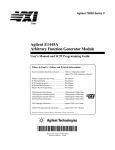
Bit and Byte Order
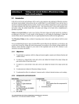
In illustrations of data structures in memory, smaller addresses appear toward the bottom of the
figure; addresses increase toward the top. Bit positions are numbered from right to left. The
numerical value of a set bit is equal to two raised to the power of the bit position. Intel Architecture processors are “little endian” machines; this means the bytes of a word are numbered
starting from the least significant byte. Figure 1-1 illustrates these conventions.
1-5
ABOUT THIS MANUAL
Highest
31
Address
Data Structure
8 7
24 23
16 15
Byte 3
Byte 2
Byte 1
Bit offset
0
Byte 0
28
24
20
16
12
8
4
0
Lowest
Address
Byte Offset
Figure 1-1. Bit and Byte Order
1.4.2.
Reserved Bits and Software Compatibility
In many register and memory layout descriptions, certain bits are marked as reserved. When
bits are marked as reserved, it is essential for compatibility with future processors that software
treat these bits as having a future, though unknown, effect. The behavior of reserved bits should
be regarded as not only undefined, but unpredictable. Software should follow these guidelines
in dealing with reserved bits:
•
Do not depend on the states of any reserved bits when testing the values of registers which
contain such bits. Mask out the reserved bits before testing.
•
•
•
Do not depend on the states of any reserved bits when storing to memory or to a register.
Do not depend on the ability to retain information written into any reserved bits.
When loading a register, always load the reserved bits with the values indicated in the
documentation, if any, or reload them with values previously read from the same register.
NOTE
Avoid any software dependence upon the state of reserved bits in Intel Architecture registers. Depending upon the values of reserved register bits will
make software dependent upon the unspecified manner in which the
processor handles these bits. Programs that depend upon reserved values risk
incompatibility with future processors.
1-6
ABOUT THIS MANUAL
1.4.3.
Instruction Operands
When instructions are represented symbolically, a subset of the Intel Architecture assembly
language is used. In this subset, an instruction has the following format:
label: mnemonic argument1, argument2, argument3
where:
•
•
A label is an identifier which is followed by a colon.
•
The operands argument1, argument2, and argument3 are optional. There may be from zero
to three operands, depending on the opcode. When present, they take the form of either
literals or identifiers for data items. Operand identifiers are either reserved names of
registers or are assumed to be assigned to data items declared in another part of the
program (which may not be shown in the example).
A mnemonic is a reserved name for a class of instruction opcodes which have the same
function.
When two operands are present in an arithmetic or logical instruction, the right operand is the
source and the left operand is the destination.
For example:
LOADREG: MOV EAX, SUBTOTAL
In this example, LOADREG is a label, MOV is the mnemonic identifier of an opcode, EAX is
the destination operand, and SUBTOTAL is the source operand. Some assembly languages put
the source and destination in reverse order.
1.4.4.
Hexadecimal and Binary Numbers
Base 16 (hexadecimal) numbers are represented by a string of hexadecimal digits followed by
the character H (for example, F82EH). A hexadecimal digit is a character from the following
set: 0, 1, 2, 3, 4, 5, 6, 7, 8, 9, A, B, C, D, E, and F.
Base 2 (binary) numbers are represented by a string of 1s and 0s, sometimes followed by the
character B (for example, 1010B). The “B” designation is only used in situations where confusion as to the type of number might arise.
1.4.5.
Segmented Addressing
The processor uses byte addressing. This means memory is organized and accessed as a
sequence of bytes. Whether one or more bytes are being accessed, a byte address is used to
locate the byte or bytes of memory. The range of memory that can be addressed is called an
address space.
1-7
ABOUT THIS MANUAL
The processor also supports segmented addressing. This is a form of addressing where a
program may have many independent address spaces, called segments. For example, a program
can keep its code (instructions) and stack in separate segments. Code addresses would always
refer to the code space, and stack addresses would always refer to the stack space. The following
notation is used to specify a byte address within a segment:
Segment-register:Byte-address
For example, the following segment address identifies the byte at address FF79H in the segment
pointed by the DS register:
DS:FF79H
The following segment address identifies an instruction address in the code segment. The CS
register points to the code segment and the EIP register contains the address of the instruction.
CS:EIP
1.4.6.
Exceptions
An exception is an event that typically occurs when an instruction causes an error. For example,
an attempt to divide by zero generates an exception. However, some exceptions, such as breakpoints, occur under other conditions. Some types of exceptions may provide error codes. An
error code reports additional information about the error. An example of the notation used to
show an exception and error code is shown below.
#PF(fault code)
This example refers to a page-fault exception under conditions where an error code naming a
type of fault is reported. Under some conditions, exceptions which produce error codes may not
be able to report an accurate code. In this case, the error code is zero, as shown below for a
general-protection exception.
#GP(0)
Refer to Chapter 5, Interrupt and Exception Handling, in the Intel Architecture Software Developer’s Manual, Volume 3, for a list of exception mnemonics and their descriptions.
1-8
ABOUT THIS MANUAL
1.5.
RELATED LITERATURE
The following books contain additional material related to Intel processors:
•
•
•
•
•
Intel Pentium® II Processor Specification Update, Order Number 243337-010.
•
Pentium® Pro Processor Family Developer’s Manual, Volume 1: Specifications, Order
Number 242690-001.
•
•
•
•
•
•
•
•
Pentium® Processor Family Developer’s Manual, Order Number 241428.
•
•
•
•
•
•
376 Embedded Processor Programmer’s Reference Manual, Order Number 240314.
Intel Pentium® Pro Processor Specification Update, Order Number 242689.
Intel Pentium® Processor Specification Update, Order Number 242480.
AP-485, Intel Processor Identification and the CPUID Instruction, Order Number 241618.
AP-578, Software and Hardware Considerations for FPU Exception Handlers for Intel
Architecture Processors, Order Number 242415-001.
Intel486™ Microprocessor Data Book, Order Number 240440.
Intel486™ SX CPU/Intel487™ SX Math Coprocessor Data Book, Order Number 240950.
Intel486™ DX2 Microprocessor Data Book, Order Number 241245.
Intel486™ Microprocessor Product Brief Book, Order Number 240459.
Intel386™ Processor Hardware Reference Manual, Order Number 231732.
Intel386™ Processor System Software Writer's Guide, Order Number 231499.
Intel386™ High-Performance 32-Bit CHMOS Microprocessor with Integrated Memory
Management, Order Number 231630.
80387 DX User’s Manual Programmer’s Reference, Order Number 231917.
376 High-Performance 32-Bit Embedded Processor, Order Number 240182.
Intel386™ SX Microprocessor, Order Number 240187.
Microprocessor and Peripheral Handbook (Vol. 1), Order Number 230843.
AP-528, Optimizations for Intel’s 32-Bit Processors, Order Number 242816-001.
1-9
ABOUT THIS MANUAL
1-10
2
Instruction Format
CHAPTER 2
INSTRUCTION FORMAT
This chapter describes the instruction format for all Intel Architecture processors.
2.1.
GENERAL INSTRUCTION FORMAT
All Intel Architecture instruction encodings are subsets of the general instruction format shown
in Figure 2-1. Instructions consist of optional instruction prefixes (in any order), one or two
primary opcode bytes, an addressing-form specifier (if required) consisting of the ModR/M byte
and sometimes the SIB (Scale-Index-Base) byte, a displacement (if required), and an immediate
data field (if required).
Instruction
Prefixes
Opcode
ModR/M
SIB
Displacement
Immediate
Up to four
prefixes of
1-byte each
(optional)
1 or 2 byte
opcode
1 byte
(if required)
1 byte
(if required)
Address
displacement
of 1, 2, or 4
bytes or none
Immediate
data of
1, 2, or 4
bytes or none
7
3 2
7
32
0
Reg/
R/M
Opcode
65
Mod
6 5
Scale
Index
0
Base
Figure 2-1. Intel Architecture Instruction Format
2.2.
INSTRUCTION PREFIXES
The instruction prefixes are divided into four groups, each with a set of allowable prefix codes:
•
Lock and repeat prefixes.
— F0H—LOCK prefix.
— F2H—REPNE/REPNZ prefix (used only with string instructions).
— F3H—REP prefix (used only with string instructions).
— F3H—REPE/REPZ prefix (used only with string instructions).
— F3H—Streaming SIMD Extensions prefix.
2-1
INSTRUCTION FORMAT
•
Segment override.
— 2EH—CS segment override prefix.
— 36H—SS segment override prefix.
— 3EH—DS segment override prefix.
— 26H—ES segment override prefix.
— 64H—FS segment override prefix.
— 65H—GS segment override prefix.
•
•
Operand-size override, 66H
Address-size override, 67H
For each instruction, one prefix may be used from each of these groups and be placed in any
order. The effect of redundant prefixes (more than one prefix from a group) is undefined and
may vary from processor to processor.
•
Streaming SIMD Extensions prefix, 0FH
The nature of Streaming SIMD Extensions allows the use of existing instruction formats.
Instructions use the ModR/M format and are preceded by the 0F prefix byte. In general, operations are not duplicated to provide two directions (i.e. separate load and store variants). For more
information, see Section B.4.1., “Instruction Prefixes” in Appendix B, Instruction Formats and
Encodings.
2.3.
OPCODE
The primary opcode is either 1 or 2 bytes. An additional 3-bit opcode field is sometimes encoded
in the ModR/M byte. Smaller encoding fields can be defined within the primary opcode. These
fields define the direction of the operation, the size of displacements, the register encoding,
condition codes, or sign extension. The encoding of fields in the opcode varies, depending on
the class of operation.
2.4.
MODR/M AND SIB BYTES
Most instructions that refer to an operand in memory have an addressing-form specifier byte
(called the ModR/M byte) following the primary opcode. The ModR/M byte contains three
fields of information:
•
The mod field combines with the r/m field to form 32 possible values: eight registers and
24 addressing modes.
•
The reg/opcode field specifies either a register number or three more bits of opcode information. The purpose of the reg/opcode field is specified in the primary opcode.
•
The r/m field can specify a register as an operand or can be combined with the mod field to
encode an addressing mode.
2-2
INSTRUCTION FORMAT
Certain encodings of the ModR/M byte require a second addressing byte, the SIB byte, to fully
specify the addressing form. The base-plus-index and scale-plus-index forms of 32-bit
addressing require the SIB byte. The SIB byte includes the following fields:
•
•
•
The scale field specifies the scale factor.
The index field specifies the register number of the index register.
The base field specifies the register number of the base register.
Refer to Section 2.6. for the encodings of the ModR/M and SIB bytes.
2.5.
DISPLACEMENT AND IMMEDIATE BYTES
Some addressing forms include a displacement immediately following either the ModR/M or
SIB byte. If a displacement is required, it can be 1, 2, or 4 bytes.
If the instruction specifies an immediate operand, the operand always follows any displacement
bytes. An immediate operand can be 1, 2, or 4 bytes.
2.6.
ADDRESSING-MODE ENCODING OF MODR/M AND SIB
BYTES
The values and the corresponding addressing forms of the ModR/M and SIB bytes are shown in
Tables 2-1 through 2-3. The 16-bit addressing forms specified by the ModR/M byte are in Table
2-1, and the 32-bit addressing forms specified by the ModR/M byte are in Table 2-2. Table 2-3
shows the 32-bit addressing forms specified by the SIB byte.
In Tables 2-1 and 2-2, the first column (labeled “Effective Address”) lists 32 different effective
addresses that can be assigned to one operand of an instruction by using the Mod and R/M fields
of the ModR/M byte. The first 24 give the different ways of specifying a memory location; the
last eight (specified by the Mod field encoding 11B) give the ways of specifying the general
purpose, MMX™ technology, and SIMD floating-point registers. Each of the register encodings
list five possible registers. For example, the first register-encoding (selected by the R/M field
encoding of 000B) indicates the general-purpose registers EAX, AX or AL, the MMX™ technology register MM0, or the SIMD floating-point register XMM0. Which of these five registers
is used is determined by the opcode byte and the operand-size attribute, which select either the
EAX register (32 bits) or AX register (16 bits).
The second and third columns in Tables 2-1 and 2-2 gives the binary encodings of the Mod and
R/M fields in the ModR/M byte, respectively, required to obtain the associated effective address
listed in the first column. All 32 possible combinations of the Mod and R/M fields are listed.
Across the top of Tables 2-1 and 2-2, the eight possible values of the 3-bit Reg/Opcode field are
listed, in decimal (sixth row from top) and in binary (seventh row from top). The seventh row is
labeled “REG=”, which represents the use of these three bits to give the location of a second
operand, which must be a general-purpose register, an MMX™ technology register, or a SIMD
floating-point register. If the instruction does not require a second operand to be specified, then
the 3 bits of the Reg/Opcode field may be used as an extension of the opcode, which is repre-
2-3
INSTRUCTION FORMAT
sented by the sixth row, labeled “/digit (Opcode)”. The five rows above give the byte, word, and
doubleword general-purpose registers; the MMX™ technology registers; the Streaming SIMD
Extensions registers; and SIMD floating-point registers that correspond to the register numbers,
with the same assignments as for the R/M field when Mod field encoding is 11B. As with the
R/M field register options, which of the five possible registers is used is determined by the
opcode byte along with the operand-size attribute.
The body of Tables 2-1 and 2-2 (under the label “Value of ModR/M Byte (in Hexadecimal)”)
contains a 32 by 8 array giving all of the 256 values of the ModR/M byte, in hexadecimal. Bits
3, 4 and 5 are specified by the column of the table in which a byte resides, and the row specifies
bits 0, 1 and 2, and also bits 6 and 7.
2-4
INSTRUCTION FORMAT
Table 2-1. 16-Bit Addressing Forms with the ModR/M Byte
AL
AX
EAX
MM0
XMM0
0
000
r8(/r)
r16(/r)
r32(/r)
mm(/r)
xmm(/r)
/digit (Opcode)
REG =
Effective
Address
CL
CX
ECX
MM1
XMM1
1
001
DL
DX
EDX
MM2
XMM2
2
010
BL
BX
EBX
MM3
XMM3
3
011
AH
SP
ESP
MM4
XMM4
4
100
CH
BP1
EBP
MM5
XMM5
5
101
DH
SI
ESI
MM6
XMM6
6
110
BH
DI
EDI
MM7
XMM7
7
111
Mod
R/M
Value of ModR/M Byte (in Hexadecimal)
[BX+SI]
[BX+DI]
[BP+SI]
[BP+DI]
[SI]
[DI]
disp162
[BX]
00
000
001
010
011
100
101
110
111
00
01
02
03
04
05
06
07
08
09
0A
0B
0C
0D
0E
0F
10
11
12
13
14
15
16
17
18
19
1A
1B
1C
1D
1E
1F
20
21
22
23
24
25
26
27
28
29
2A
2B
2C
2D
2E
2F
30
31
32
33
34
35
36
37
38
39
3A
3B
3C
3D
3E
3F
[BX+SI]+disp83
[BX+DI]+disp8
[BP+SI]+disp8
[BP+DI]+disp8
[SI]+disp8
[DI]+disp8
[BP]+disp8
[BX]+disp8
01
000
001
010
011
100
101
110
111
40
41
42
43
44
45
46
47
48
49
4A
4B
4C
4D
4E
4F
50
51
52
53
54
55
56
57
58
59
5A
5B
5C
5D
5E
5F
60
61
62
63
64
65
66
67
68
69
6A
6B
6C
6D
6E
6F
70
71
72
73
74
75
76
77
78
79
7A
7B
7C
7D
7E
7F
[BX+SI]+disp16
[BX+DI]+disp16
[BP+SI]+disp16
[BP+DI]+disp16
[SI]+disp16
[DI]+disp16
[BP]+disp16
[BX]+disp16
10
000
001
010
011
100
101
110
111
80
81
82
83
84
85
86
87
88
89
8A
8B
8C
8D
8E
8F
90
91
92
93
94
95
96
97
98
99
9A
9B
9C
9D
9E
9F
A0
A1
A2
A3
A4
A5
A6
A7
A8
A9
AA
AB
AC
AD
AE
AF
B0
B1
B2
B3
B4
B5
B6
B7
B8
B9
BA
BB
BC
BD
BE
BF
EAX/AX/AL/MM0/XMM0
ECX/CX/CL/MM1/XMM1
EDX/DX/DL/MM2/XMM2
EBX/BX/BL/MM3/XMM3
ESP/SP/AHMM4/XMM4
EBP/BP/CH/MM5/XMM5
ESI/SI/DH/MM6/XMM6
EDI/DI/BH/MM7/XMM7
11
000
001
010
011
100
101
110
111
C0
C1
C2
C3
C4
C5
C6
C7
C8
C9
CA
CB
CC
CD
CE
CF
D0
D1
D2
D3
D4
D5
D6
D7
D8
D9
DA
DB
DC
DD
DE
DF
E0
EQ
E2
E3
E4
E5
E6
E7
E8
E9
EA
EB
EC
ED
EE
EF
F0
F1
F2
F3
F4
F5
F6
F7
F8
F9
FA
FB
FC
FD
FE
FF
NOTES:
1. The default segment register is SS for the effective addresses containing a BP index, DS for other effective addresses.
2. The “disp16” nomenclature denotes a 16-bit displacement following the ModR/M byte, to be added to the
index.
3. The “disp8” nomenclature denotes an 8-bit displacement following the ModR/M byte, to be sign-extended
and added to the index.
2-5
INSTRUCTION FORMAT
Table 2-2. 32-Bit Addressing Forms with the ModR/M Byte
AL
AX
EAX
MM0
XMM0
0
000
r8(/r)
r16(/r)
r32(/r)
mm(/r)
xmm(/r)
/digit (Opcode)
REG =
Effective
Address
CL
CX
ECX
MM1
XMM1
1
001
DL
DX
EDX
MM2
XMM2
2
010
BL
BX
EBX
MM3
XMM3
3
011
AH
SP
ESP
MM4
XMM4
4
100
CH
BP
EBP
MM5
XMM5
5
101
DH
SI
ESI
MM6
XMM6
6
110
BH
DI
EDI
MM7
XMM7
7
111
Mod
R/M
Value of ModR/M Byte (in Hexadecimal)
[EAX]
[ECX]
[EDX]
[EBX]
[--][--]1
disp322
[ESI]
[EDI]
00
000
001
010
011
100
101
110
111
00
01
02
03
04
05
06
07
08
09
0A
0B
0C
0D
0E
0F
10
11
12
13
14
15
16
17
18
19
1A
1B
1C
1D
1E
1F
20
21
22
23
24
25
26
27
28
29
2A
2B
2C
2D
2E
2F
30
31
32
33
34
35
36
37
38
39
3A
3B
3C
3D
3E
3F
disp8[EAX]3
disp8[ECX]
disp8[EDX]
disp8[EBX];
disp8[--][--]
disp8[EBP]
disp8[ESI]
disp8[EDI]
01
000
001
010
011
100
101
110
111
40
41
42
43
44
45
46
47
48
49
4A
4B
4C
4D
4E
4F
50
51
52
53
54
55
56
57
58
59
5A
5B
5C
5D
5E
5F
60
61
62
63
64
65
66
67
68
69
6A
6B
6C
6D
6E
6F
70
71
72
73
74
75
76
77
78
79
7A
7B
7C
7D
7E
7F
disp32[EAX]
disp32[ECX]
disp32[EDX]
disp32[EBX]
disp32[--][--]
disp32[EBP]
disp32[ESI]
disp32[EDI]
10
000
001
010
011
100
101
110
111
80
81
82
83
84
85
86
87
88
89
8A
8B
8C
8D
8E
8F
90
91
92
93
94
95
96
97
98
99
9A
9B
9C
9D
9E
9F
A0
A1
A2
A3
A4
A5
A6
A7
A8
A9
AA
AB
AC
AD
AE
AF
B0
B1
B2
B3
B4
B5
B6
B7
B8
B9
BA
BB
BC
BD
BE
BF
EAX/AX/AL/MM0/XMM0
ECX/CX/CL/MM1/XMM1
EDX/DX/DL/MM2XMM2
EBX/BX/BL/MM3/XMM3
ESP/SP/AH/MM4/XMM4
EBP/BP/CH/MM5/XMM5
ESI/SI/DH/MM6/XMM6
EDI/DI/BH/MM7/XMM7
11
000
001
010
011
100
101
110
111
C0
C1
C2
C3
C4
C5
C6
C7
C8
C9
CA
CB
CC
CD
CE
CF
D0
D1
D2
D3
D4
D5
D6
D7
D8
D9
DA
DB
DC
DD
DE
DF
E0
E1
E2
E3
E4
E5
E6
E7
E8
E9
EA
EB
EC
ED
EE
EF
F0
F1
F2
F3
F4
F5
F6
F7
F8
F9
FA
FB
FC
FD
FE
FF
NOTES:
1. The [--][--] nomenclature means a SIB follows the ModR/M byte.
2. The disp32 nomenclature denotes a 32-bit displacement following the SIB byte, to be added to the index.
3. The disp8 nomenclature denotes an 8-bit displacement following the SIB byte, to be sign-extended and
added to the index.
2-6
INSTRUCTION FORMAT
Table 2-3 is organized similarly to Tables 2-1 and 2-2, except that its body gives the 256 possible
values of the SIB byte, in hexadecimal. Which of the 8 general-purpose registers will be used as
base is indicated across the top of the table, along with the corresponding values of the base field
(bits 0, 1 and 2) in decimal and binary. The rows indicate which register is used as the index
(determined by bits 3, 4 and 5) along with the scaling factor (determined by bits 6 and 7).
Table 2-3. 32-Bit Addressing Forms with the SIB Byte
EAX
0
000
r32
Base =
Base =
Scaled Index
ECX
1
001
EDX
2
010
EBX
3
011
ESP
4
100
[*]
5
101
ESI
6
110
EDI
7
111
SS
Index
Value of SIB Byte (in Hexadecimal)
[EAX]
[ECX]
[EDX]
[EBX]
none
[EBP]
[ESI]
[EDI]
00
000
001
010
011
100
101
110
111
00
08
10
18
20
28
30
38
01
09
11
19
21
29
31
39
02
0A
12
1A
22
2A
32
3A
03
0B
13
1B
23
2B
33
3B
04
0C
14
1C
24
2C
34
3C
05
0D
15
1D
25
2D
35
3D
06
0E
16
1E
26
2E
36
3E
07
0F
17
1F
27
2F
37
3F
[EAX*2]
[ECX*2]
[EDX*2]
[EBX*2]
none
[EBP*2]
[ESI*2]
[EDI*2]
01
000
001
010
011
100
101
110
111
40
48
50
58
60
68
70
78
41
49
51
59
61
69
71
79
42
4A
52
5A
62
6A
72
7A
43
4B
53
5B
63
6B
73
7B
44
4C
54
5C
64
6C
74
7C
45
4D
55
5D
65
6D
75
7D
46
4E
56
5E
66
6E
76
7E
47
4F
57
5F
67
6F
77
7F
[EAX*4]
[ECX*4]
[EDX*4]
[EBX*4]
none
[EBP*4]
[ESI*4]
[EDI*4]
10
000
001
010
011
100
101
110
111
80
88
90
98
A0
A8
B0
B8
81
89
91
89
A1
A9
B1
B9
82
8A
92
9A
A2
AA
B2
BA
83
8B
93
9B
A3
AB
B3
BB
84
8C
94
9C
A4
AC
B4
BC
85
8D
95
9D
A5
AD
B5
BD
86
8E
96
9E
A6
AE
B6
BE
87
8F
97
9F
A7
AF
B7
BF
[EAX*8]
[ECX*8]
[EDX*8]
[EBX*8]
none
[EBP*8]
[ESI*8]
[EDI*8]
11
000
001
010
011
100
101
110
111
C0
C8
D0
D8
E0
E8
F0
F8
C1
C9
D1
D9
E1
E9
F1
F9
C2
CA
D2
DA
E2
EA
F2
FA
C3
CB
D3
DB
E3
EB
F3
FB
C4
CC
D4
DC
E4
EC
F4
FC
C5
CD
D5
DD
E5
ED
F5
FD
C6
CE
D6
DE
E6
EE
F6
FE
C7
CF
D7
DF
E7
EF
F7
FF
NOTE:
1. The [*] nomenclature means a disp32 with no base if MOD is 00, [EBP] otherwise. This provides the
following addressing modes:
disp32[index]
disp8[EBP][index]
disp32[EBP][index]
(MOD=00).
(MOD=01).
(MOD=10).
2-7
INSTRUCTION FORMAT
2-8
3
Instruction Set
Reference
CHAPTER 3
INSTRUCTION SET REFERENCE
This chapter describes the complete Intel Architecture instruction set, including the integer,
floating-point, MMX™ technology, Streaming SIMD Extensions, and system instructions. The
instruction descriptions are arranged in alphabetical order. For each instruction, the forms are
given for each operand combination, including the opcode, operands required, and a description.
Also given for each instruction are a description of the instruction and its operands, an operational description, a description of the effect of the instructions on flags in the EFLAGS register,
and a summary of the exceptions that can be generated.
3.1.
INTERPRETING THE INSTRUCTION REFERENCE PAGES
This section describes the information contained in the various sections of the instruction reference pages that make up the majority of this chapter. It also explains the notational conventions
and abbreviations used in these sections.
3.1.1.
Instruction Format
The following is an example of the format used for each Intel Architecture instruction description in this chapter:
3-1
INSTRUCTION SET REFERENCE
CMC—Complement Carry Flag
Opcode
Instruction
Description
F5
CMC
Complement carry flag
3.1.1.1.
OPCODE COLUMN
The “Opcode” column gives the complete object code produced for each form of the instruction.
When possible, the codes are given as hexadecimal bytes, in the same order in which they appear
in memory. Definitions of entries other than hexadecimal bytes are as follows:
•
/digit—A digit between 0 and 7 indicates that the ModR/M byte of the instruction uses
only the r/m (register or memory) operand. The reg field contains the digit that provides an
extension to the instruction's opcode.
•
/r—Indicates that the ModR/M byte of the instruction contains both a register operand and
an r/m operand.
•
cb, cw, cd, cp—A 1-byte (cb), 2-byte (cw), 4-byte (cd), or 6-byte (cp) value following the
opcode that is used to specify a code offset and possibly a new value for the code segment
register.
•
ib, iw, id—A 1-byte (ib), 2-byte (iw), or 4-byte (id) immediate operand to the instruction
that follows the opcode, ModR/M bytes or scale-indexing bytes. The opcode determines if
the operand is a signed value. All words and doublewords are given with the low-order
byte first.
•
+rb, +rw, +rd—A register code, from 0 through 7, added to the hexadecimal byte given at
the left of the plus sign to form a single opcode byte. The register codes are given in Table
3-1.
•
+i—A number used in floating-point instructions when one of the operands is ST(i) from
the FPU register stack. The number i (which can range from 0 to 7) is added to the
hexadecimal byte given at the left of the plus sign to form a single opcode byte.
3-2
INSTRUCTION SET REFERENCE
Table 3-1. Register Encodings Associated with the +rb, +rw, and +rd Nomenclature
rb
rw
rd
AL
=
0
AX
=
0
EAX
=
0
CL
=
1
CX
=
1
ECX
=
1
DL
=
2
DX
=
2
EDX
=
2
BL
=
3
BX
=
3
EBX
=
3
rb
rw
rd
AH
=
4
SP
=
4
ESP
=
4
CH
=
5
BP
=
5
EBP
=
5
DH
=
6
SI
=
6
ESI
=
6
BH
=
7
DI
=
7
EDI
=
7
3.1.1.2.
INSTRUCTION COLUMN
The “Instruction” column gives the syntax of the instruction statement as it would appear in an
ASM386 program. The following is a list of the symbols used to represent operands in the
instruction statements:
•
rel8—A relative address in the range from 128 bytes before the end of the instruction to
127 bytes after the end of the instruction.
•
rel16 and rel32—A relative address within the same code segment as the instruction
assembled. The rel16 symbol applies to instructions with an operand-size attribute of 16
bits; the rel32 symbol applies to instructions with an operand-size attribute of 32 bits.
•
ptr16:16 and ptr16:32—A far pointer, typically in a code segment different from that of
the instruction. The notation 16:16 indicates that the value of the pointer has two parts. The
value to the left of the colon is a 16-bit selector or value destined for the code segment
register. The value to the right corresponds to the offset within the destination segment.
The ptr16:16 symbol is used when the instruction's operand-size attribute is 16 bits; the
ptr16:32 symbol is used when the operand-size attribute is 32 bits.
•
•
•
r8—One of the byte general-purpose registers AL, CL, DL, BL, AH, CH, DH, or BH.
•
imm8—An immediate byte value. The imm8 symbol is a signed number between –128
and +127 inclusive. For instructions in which imm8 is combined with a word or
doubleword operand, the immediate value is sign-extended to form a word or doubleword.
The upper byte of the word is filled with the topmost bit of the immediate value.
•
imm16—An immediate word value used for instructions whose operand-size attribute is
16 bits. This is a number between –32,768 and +32,767 inclusive.
r16—One of the word general-purpose registers AX, CX, DX, BX, SP, BP, SI, or DI.
r32—One of the doubleword general-purpose registers EAX, ECX, EDX, EBX, ESP, EBP,
ESI, or EDI.
3-3
INSTRUCTION SET REFERENCE
•
imm32—An immediate doubleword value used for instructions whose operandsize attribute is 32 bits. It allows the use of a number between +2,147,483,647 and
–2,147,483,648 inclusive.
•
r/m8—A byte operand that is either the contents of a byte general-purpose register (AL,
BL, CL, DL, AH, BH, CH, and DH), or a byte from memory.
•
r/m16—A word general-purpose register or memory operand used for instructions whose
operand-size attribute is 16 bits. The word general-purpose registers are: AX, BX, CX,
DX, SP, BP, SI, and DI. The contents of memory are found at the address provided by the
effective address computation.
•
r/m32—A doubleword general-purpose register or memory operand used for instructions
whose operand-size attribute is 32 bits. The doubleword general-purpose registers are:
EAX, EBX, ECX, EDX, ESP, EBP, ESI, and EDI. The contents of memory are found at the
address provided by the effective address computation.
•
•
m—A 16- or 32-bit operand in memory.
•
m16—A word operand in memory, usually expressed as a variable or array name, but
pointed to by the DS:(E)SI or ES:(E)DI registers. This nomenclature is used only with the
string instructions.
•
m32—A doubleword operand in memory, usually expressed as a variable or array name,
but pointed to by the DS:(E)SI or ES:(E)DI registers. This nomenclature is used only with
the string instructions.
•
m64—A memory quadword operand in memory. This nomenclature is used only with the
CMPXCHG8B instruction.
•
m128—A memory double quadword operand in memory. This nomenclature is used only
with the Streaming SIMD Extensions.
•
m16:16, m16:32—A memory operand containing a far pointer composed of two numbers.
The number to the left of the colon corresponds to the pointer's segment selector. The
number to the right corresponds to its offset.
•
m16&32, m16&16, m32&32—A memory operand consisting of data item pairs whose
sizes are indicated on the left and the right side of the ampersand. All memory addressing
modes are allowed. The m16&16 and m32&32 operands are used by the BOUND
instruction to provide an operand containing an upper and lower bounds for array indices.
The m16&32 operand is used by LIDT and LGDT to provide a word with which to load
the limit field, and a doubleword with which to load the base field of the corresponding
GDTR and IDTR registers.
•
moffs8, moffs16, moffs32—A simple memory variable (memory offset) of type byte,
word, or doubleword used by some variants of the MOV instruction. The actual address is
given by a simple offset relative to the segment base. No ModR/M byte is used in the
3-4
m8—A byte operand in memory, usually expressed as a variable or array name, but
pointed to by the DS:(E)SI or ES:(E)DI registers. This nomenclature is used only with the
string instructions and the XLAT instruction.
INSTRUCTION SET REFERENCE
instruction. The number shown with moffs indicates its size, which is determined by the
address-size attribute of the instruction.
•
Sreg—A segment register. The segment register bit assignments are ES=0, CS=1, SS=2,
DS=3, FS=4, and GS=5.
•
m32real, m64real, m80real—A single-, double-, and extended-real (respectively)
floating-point operand in memory.
•
m16int, m32int, m64int—A word-, short-, and long-integer (respectively) floating-point
operand in memory.
•
•
•
ST or ST(0)—The top element of the FPU register stack.
•
xmm—A SIMD floating-point register. The 128-bit SIMD floating-point registers are:
XMM0 through XMM7.
•
mm/m32—The low order 32 bits of an MMX™ technology register or a 32-bit memory
operand. The 64-bit MMX™ technology registers are: MM0 through MM7. The contents
of memory are found at the address provided by the effective address computation.
•
mm/m64—An MMX™ technology register or a 64-bit memory operand. The 64-bit
MMX™ technology registers are: MM0 through MM7. The contents of memory are found
at the address provided by the effective address computation.
•
xmm/m32—A SIMD floating-points register or a 32-bit memory operand. The 128-bit
SIMD floating-point registers are XMM0 through XMM7. The contents of memory are
found at the address provided by the effective address computation.
•
xmm/m64—A SIMD floating-point register or a 64-bit memory operand. The 64-bit
SIMD floating-point registers are XMM0 through XMM7. The contents of memory are
found at the address provided by the effective address computation.
•
xmm/m128—A SIMD floating-point register or a 128-bit memory operand. The 128-bit
SIMD floating-point registers are XMM0 through XMM7. The contents of memory are
found at the address provided by the effective address computation.
ST(i)—The ith element from the top of the FPU register stack. (i = 0 through 7)
mm—An MMX™ technology register. The 64-bit MMX™ technology registers are:
MM0 through MM7.
3.1.1.3.
DESCRIPTION COLUMN
The “Description” column following the “Instruction” column briefly explains the various
forms of the instruction. The following “Description” and “Operation” sections contain more
details of the instruction's operation.
3.1.1.4.
DESCRIPTION
The “Description” section describes the purpose of the instructions and the required operands.
It also discusses the effect of the instruction on flags.
3-5
INSTRUCTION SET REFERENCE
3.1.2.
Operation
The “Operation” section contains an algorithmic description (written in pseudo-code) of the
instruction. The pseudo-code uses a notation similar to the Algol or Pascal language. The algorithms are composed of the following elements:
•
•
Comments are enclosed within the symbol pairs “(*” and “*)”.
•
A register name implies the contents of the register. A register name enclosed in brackets
implies the contents of the location whose address is contained in that register. For
example, ES:[DI] indicates the contents of the location whose ES segment relative address
is in register DI. [SI] indicates the contents of the address contained in register SI relative
to SI’s default segment (DS) or overridden segment.
•
Parentheses around the “E” in a general-purpose register name, such as (E)SI, indicates
that an offset is read from the SI register if the current address-size attribute is 16 or is read
from the ESI register if the address-size attribute is 32.
•
Brackets are also used for memory operands, where they mean that the contents of the
memory location is a segment-relative offset. For example, [SRC] indicates that the
contents of the source operand is a segment-relative offset.
•
•
A ← B; indicates that the value of B is assigned to A.
•
Compound statements are enclosed in keywords, such as IF, THEN, ELSE, and FI for an if
statement, DO and OD for a do statement, or CASE ... OF and ESAC for a case statement.
The symbols =, ≠, ≥, and ≤ are relational operators used to compare two values, meaning
equal, not equal, greater or equal, less or equal, respectively. A relational expression such
as A = B is TRUE if the value of A is equal to B; otherwise it is FALSE.
The expression “<< COUNT” and “>> COUNT” indicates that the destination operand
should be shifted left or right, respectively, by the number of bits indicated by the count
operand.
The following identifiers are used in the algorithmic descriptions:
•
OperandSize and AddressSize—The OperandSize identifier represents the operand-size
attribute of the instruction, which is either 16 or 32 bits. The AddressSize identifier
represents the address-size attribute, which is either 16 or 32 bits. For example, the
following pseudo-code indicates that the operand-size attribute depends on the form of the
CMPS instruction used.
IF instruction = CMPSW
THEN OperandSize ← 16;
ELSE
IF instruction = CMPSD
THEN OperandSize ← 32;
FI;
FI;
3-6
INSTRUCTION SET REFERENCE
Refer to Section 3.8., Operand-Size and Address-Size Attributes in Chapter 3, Basic
Execution Environment of the Intel Architecture Software Developer’s Manual, Volume 1,
for general guidelines on how these attributes are determined.
•
StackAddrSize—Represents the stack address-size attribute associated with the
instruction, which has a value of 16 or 32 bits. For more information, refer to Section
4.2.3., Address-Size Attributes for Stack Accesses in Chapter 4, Procedure Calls,
Interrupts, and Exceptions of the Intel Architecture Software Developer’s Manual, Volume
1.
•
•
SRC—Represents the source operand.
DEST—Represents the destination operand.
The following functions are used in the algorithmic descriptions:
•
ZeroExtend(value)—Returns a value zero-extended to the operand-size attribute of the
instruction. For example, if the operand-size attribute is 32, zero extending a byte value of
–10 converts the byte from F6H to a doubleword value of 000000F6H. If the value passed
to the ZeroExtend function and the operand-size attribute are the same size, ZeroExtend
returns the value unaltered.
•
SignExtend(value)—Returns a value sign-extended to the operand-size attribute of the
instruction. For example, if the operand-size attribute is 32, sign extending a byte
containing the value –10 converts the byte from F6H to a doubleword value of
FFFFFFF6H. If the value passed to the SignExtend function and the operand-size attribute
are the same size, SignExtend returns the value unaltered.
•
SaturateSignedWordToSignedByte—Converts a signed 16-bit value to a signed 8-bit
value. If the signed 16-bit value is less than –128, it is represented by the saturated value
–128 (80H); if it is greater than 127, it is represented by the saturated value 127 (7FH).
•
SaturateSignedDwordToSignedWord—Converts a signed 32-bit value to a signed 16-bit
value. If the signed 32-bit value is less than –32768, it is represented by the saturated value
–32768 (8000H); if it is greater than 32767, it is represented by the saturated value 32767
(7FFFH).
•
SaturateSignedWordToUnsignedByte—Converts a signed 16-bit value to an unsigned
8-bit value. If the signed 16-bit value is less than zero, it is represented by the saturated
value zero (00H); if it is greater than 255, it is represented by the saturated value 255
(FFH).
•
SaturateToSignedByte—Represents the result of an operation as a signed 8-bit value. If
the result is less than –128, it is represented by the saturated value –128 (80H); if it is
greater than 127, it is represented by the saturated value 127 (7FH).
•
SaturateToSignedWord—Represents the result of an operation as a signed 16-bit value.
If the result is less than –32768, it is represented by the saturated value –32768 (8000H); if
it is greater than 32767, it is represented by the saturated value 32767 (7FFFH).
•
SaturateToUnsignedByte—Represents the result of an operation as a signed 8-bit value.
If the result is less than zero it is represented by the saturated value zero (00H); if it is
greater than 255, it is represented by the saturated value 255 (FFH).
3-7
INSTRUCTION SET REFERENCE
•
SaturateToUnsignedWord—Represents the result of an operation as a signed 16-bit
value. If the result is less than zero it is represented by the saturated value zero (00H); if it
is greater than 65535, it is represented by the saturated value 65535 (FFFFH).
•
LowOrderWord(DEST * SRC)—Multiplies a word operand by a word operand and
stores the least significant word of the doubleword result in the destination operand.
•
HighOrderWord(DEST * SRC)—Multiplies a word operand by a word operand and
stores the most significant word of the doubleword result in the destination operand.
•
Push(value)—Pushes a value onto the stack. The number of bytes pushed is determined by
the operand-size attribute of the instruction. Refer to the “Operation” section in
“PUSH—Push Word or Doubleword Onto the Stack” in this chapter for more information
on the push operation.
•
Pop() removes the value from the top of the stack and returns it. The statement EAX ←
Pop(); assigns to EAX the 32-bit value from the top of the stack. Pop will return either a
word or a doubleword depending on the operand-size attribute. Refer to the “Operation”
section in “POP—Pop a Value from the Stack” in this chapter for more information on the
pop operation.
•
PopRegisterStack—Marks the FPU ST(0) register as empty and increments the FPU
register stack pointer (TOP) by 1.
•
•
Switch-Tasks—Performs a task switch.
Bit(BitBase, BitOffset)—Returns the value of a bit within a bit string, which is a sequence
of bits in memory or a register. Bits are numbered from low-order to high-order within
registers and within memory bytes. If the base operand is a register, the offset can be in the
range 0..31. This offset addresses a bit within the indicated register. An example, the
function Bit[EAX, 21] is illustrated in Figure 3-1.
31
21
0
BitOffset = 21
Figure 3-1. Bit Offset for BIT[EAX,21]
If BitBase is a memory address, BitOffset can range from –2 GBits to 2 GBits. The
addressed bit is numbered (Offset MOD 8) within the byte at address (BitBase + (BitOffset
DIV 8)), where DIV is signed division with rounding towards negative infinity, and MOD
returns a positive number. This operation is illustrated in Figure 3-2.
3-8
INSTRUCTION SET REFERENCE
3.1.3.
Intel C/C++ Compiler Intrinsics Equivalent
The Pentium® with MMX™ technology, Pentium® II, and Pentium® III processors have characteristics that enable the development of advanced multimedia applications. This section
describes the compiler intrinsic equivalents that can be used with the Intel C/C++ Compiler.
Intrinsics are special coding extensions that allow using the syntax of C function calls and C
variables instead of hardware registers. Using these intrinsics frees programmers from having
to manage registers and assembly programming. Further, the compiler optimizes the instruction
scheduling so that executables runs faster.
The following sections discuss the intrinsics API and the MMX™ technology and SIMD
floating-point intrinsics. Each intrinsic equivalent is listed with the instruction description.
There may be additional intrinsics that do not have an instruction equivalent. It is strongly
recommended that the reader reference the compiler documentation for the complete list of
supported intrinsics. Please refer to the Intel C/C++ Compiler User’s Guide for Win32* Systems With
Streaming SIMD Extension Support (Order Number 718195-00B). Refer to Appendix C, Compiler Intrinsics and Functional Equivalents for more information on using intrinsics.
Most of the intrinsics that use __m64 operands have two different names. If two intrinsic names
are shown for the same equivalent, the first name is the intrinsic for Intel C/C++ Compiler versions prior to 4.0 and the second name should be used with the Intel C/C++ Compiler version
4.0 and future versions. The Intel C/C++ Compiler version 4.0 will support the old intrinsic
names. Programs written using pre-4.0 intrinsic names will compile with version 4.0. Version
4.0 intrinsic names will not compile on pre-4.0 compilers.
3.1.3.1.
THE INTRINSICS API
The benefit of coding with MMX™ technology intrinsics and SIMD floating-point intrinsics is
that you can use the syntax of C function calls and C variables instead of hardware registers.
This frees you from managing registers and programming assembly. Further, the compiler optimizes the instruction scheduling so that your executable runs faster. For each computational and
data manipulation instruction in the new instruction set, there is a corresponding C intrinsic that
implements it directly. The intrinsics allow you to specify the underlying implementation
(instruction selection) of an algorithm yet leave instruction scheduling and register allocation to
the compiler.
3-9
INSTRUCTION SET REFERENCE
3.1.3.2.
MMX™ TECHNOLOGY INTRINSICS
The MMX™ technology intrinsics are based on a new __m64 data type to represent the specific
contents of an MMX™ technology register. You can specify values in bytes, short integers, 32bit values, or a 64-bit object. The __m64 data type, however, is not a basic ANSI C data type,
and therefore you must observe the following usage restrictions:
•
Use __m64 data only on the left-hand side of an assignment, as a return value, or as a
parameter. You cannot use it with other arithmetic expressions ("+", ">>", and so on).
•
Use __m64 objects in aggregates, such as unions to access the byte elements and structures; the
address of an __m64 object may be taken.
•
Use __m64 data only with the MMX™ technology intrinsics described in this guide and
the Intel C/C++ Compiler User’s Guide for Win32* Systems With Streaming SIMD Extension
Support (Order Number 718195-00B). Refer to Appendix C, Compiler Intrinsics and Functional
Equivalents for more information on using intrinsics.
3.1.3.3.
SIMD FLOATING-POINT INTRINSICS
The __m128 data type is used to represent the contents of an xmm register, which is either four
packed single-precision floating-point values or one scalar single-precision number. The
__m128 data type is not a basic ANSI C datatype and therefore some restrictions are placed on
its usage:
•
Use __m128 only on the left-hand side of an assignment, as a return value, or as a
parameter. Do not use it in other arithmetic expressions such as "+" and ">>".
•
•
Do not initialize __m128 with literals; there is no way to express 128-bit constants.
•
Use __m128 data only with the intrinsics described in this user’s guide. Refer to
Appendix C, Compiler Intrinsics and Functional Equivalents for more information on using
intrinsics.
Use __m128 objects in aggregates, such as unions (for example, to access the float
elements) and structures. The address of an __m128 object may be taken.
The compiler aligns __m128 local data to 16B boundaries on the stack. Global __m128 data is
also 16B-aligned. (To align float arrays, you can use the alignment declspec described in the
following section.) Because the new instruction set treats the SIMD floating-point registers in
the same way whether you are using packed or scalar data, there is no __m32 datatype to represent scalar data as you might expect. For scalar operations, you should use the __m128 objects
and the “scalar” forms of the intrinsics; the compiler and the processor implement these operations with 32-bit memory references.
The suffixes ps and ss are used to denote “packed single” and “scalar single” precision operations. The packed floats are represented in right-to-left order, with the lowest word (right-most)
being used for scalar operations: [z, y, x, w]. To explain how memory storage reflects this,
consider the following example.
3-10
INSTRUCTION SET REFERENCE
The operation
float a[4] = { 1.0, 2.0, 3.0, 4.0 };
__m128 t = _mm_load_ps(a);
produces the same result as follows:
__m128 t = _mm_set_ps(4.0, 3.0, 2.0, 1.0);
In other words,
t = [ 4.0, 3.0, 2.0, 1.0 ]
where the “scalar” element is 1.0.
Some intrinsics are “composites” because they require more than one instruction to implement
them. You should be familiar with the hardware features provided by the Streaming SIMD
Extensions and MMX™ technology when writing programs with the intrinsics.
Keep the following three important issues in mind:
•
Certain intrinsics, such as _mm_loadr_ps and _mm_cmpgt_ss, are not directly
supported by the instruction set. While these intrinsics are convenient programming
aids, be mindful of their implementation cost.
•
Floating-point data loaded or stored as __m128 objects must generally be 16-bytealigned.
•
Some intrinsics require that their argument be immediates, that is, constant integers
(literals), due to the nature of the instruction.
•
The result of arithmetic operations acting on two NaN (Not a Number) arguments is
undefined. Therefore, FP operations using NaN arguments will not match the expected
behavior of the corresponding assembly instructions.
For a more detailed description of each intrinsic and additional information related to its usage,
refer to the Intel C/C++ Compiler User’s Guide for Win32* Systems With Streaming SIMD Extension
Support (Order Number 718195-00B). Refer to Appendix C, Compiler Intrinsics and Functional Equivalents for more information on using intrinsics.
3.1.4.
Flags Affected
The “Flags Affected” section lists the flags in the EFLAGS register that are affected by the
instruction. When a flag is cleared, it is equal to 0; when it is set, it is equal to 1. The arithmetic
and logical instructions usually assign values to the status flags in a uniform manner. For more
information, refer to Appendix A, EFLAGS Cross-Reference, of the Intel Architecture Software
Developer’s Manual, Volume 1. Non-conventional assignments are described in the “Operation”
section. The values of flags listed as undefined may be changed by the instruction in an indeterminate manner. Flags that are not listed are unchanged by the instruction.
3-11
INSTRUCTION SET REFERENCE
7
5
0 7
BitBase + 1
0 7
0
BitBase − 1
BitBase
BitOffset = +13
7
0 7
BitBase
0 7
BitBase − 1
5
0
BitBase − 2
BitOffset = −11
Figure 3-2. Memory Bit Indexing
3.1.5.
FPU Flags Affected
The floating-point instructions have an “FPU Flags Affected” section that describes how each
instruction can affect the four condition code flags of the FPU status word.
3.1.6.
Protected Mode Exceptions
The “Protected Mode Exceptions” section lists the exceptions that can occur when the instruction is executed in protected mode and the reasons for the exceptions. Each exception is given
a mnemonic that consists of a pound sign (#) followed by two letters and an optional error code
in parentheses. For example, #GP(0) denotes a general protection exception with an error code
of 0. Table 3-2 associates each two-letter mnemonic with the corresponding interrupt vector
number and exception name. Refer to Chapter 5, Interrupt and Exception Handling, of the Intel
Architecture Software Developer’s Manual, Volume 3, for a detailed description of the exceptions.
Application programmers should consult the documentation provided with their operating
systems to determine the actions taken when exceptions occur.
3.1.7.
Real-Address Mode Exceptions
The “Real-Address Mode Exceptions” section lists the exceptions that can occur when the
instruction is executed in real-address mode.
3-12
INSTRUCTION SET REFERENCE
Table 3-2. Exception Mnemonics, Names, and Vector Numbers
Vector
No.
Mnemonic
Name
Source
0
#DE
Divide Error
DIV and IDIV instructions.
1
#DB
Debug
Any code or data reference.
3
#BP
Breakpoint
INT 3 instruction.
4
#OF
Overflow
INTO instruction.
5
#BR
BOUND Range Exceeded
BOUND instruction.
6
#UD
Invalid Opcode (Undefined
Opcode)
UD2 instruction or reserved opcode.1
7
#NM
Device Not Available (No Math
Coprocessor)
Floating-point or WAIT/FWAIT
instruction.
8
#DF
Double Fault
Any instruction that can generate an
exception, an NMI, or an INTR.
10
#TS
Invalid TSS
Task switch or TSS access.
11
#NP
Segment Not Present
Loading segment registers or accessing
system segments.
12
#SS
Stack Segment Fault
Stack operations and SS register loads.
13
#GP
General Protection
Any memory reference and other
protection checks.
14
#PF
Page Fault
Any memory reference.
16
#MF
Floating-Point Error (Math Fault)
Floating-point or WAIT/FWAIT
instruction.
17
#AC
Alignment Check
Any data reference in memory.2
18
#MC
Machine Check
Model dependent.3
19
#XF
SIMD Floating-Point Numeric
Error
Streaming SIMD Extensions4
NOTES:
1. The UD2 instruction was introduced in the Pentium® Pro processor.
2. This exception was introduced in the Intel486™ processor.
3. This exception was introduced in the Pentium® processor and enhanced in the Pentium® Pro processor.
4. This exception was introduced in the Pentium® III processor.
3.1.8.
Virtual-8086 Mode Exceptions
The “Virtual-8086 Mode Exceptions” section lists the exceptions that can occur when the
instruction is executed in virtual-8086 mode.
3-13
INSTRUCTION SET REFERENCE
3.1.9.
Floating-Point Exceptions
The “Floating-Point Exceptions” section lists additional exceptions that can occur when a
floating-point instruction is executed in any mode. All of these exception conditions result in a
floating-point error exception (#MF, vector number 16) being generated. Table 3-3 associates
each one- or two-letter mnemonic with the corresponding exception name. Refer to Section 7.8.,
Floating-Point Exception Conditions in Chapter 7, Floating-Point Unit of the Intel Architecture
Software Developer’s Manual, Volume 1, for a detailed description of these exceptions.
Table 3-3. Floating-Point Exception Mnemonics and Names
Vector
No.
Mnemonic
Name
Source
#IS
#IA
Floating-point invalid operation:
- Stack overflow or underflow
- Invalid arithmetic operation
- FPU stack overflow or underflow
- Invalid FPU arithmetic operation
16
#Z
Floating-point divide-by-zero
FPU divide-by-zero
16
#D
Floating-point denormalized
operation
Attempting to operate on a denormal
number
16
#O
Floating-point numeric overflow
FPU numeric overflow
16
#U
Floating-point numeric underflow
FPU numeric underflow
16
#P
Floating-point inexact result
(precision)
Inexact result (precision)
16
3.1.10. SIMD Floating-Point Exceptions - Streaming SIMD
Extensions Only
The “SIMD Floating-Point Exceptions” section lists additional exceptions that can occur when
a SIMD floating-point instruction is executed in any mode. All of these exception conditions
result in a SIMD floating-point error exception (#XF, vector number 19) being generated. Table
3-4 associates each one-or two-letter mnemonic with the corresponding exception name. For a
detailed description of these exceptions, refer to Chapter 9, Programming with the Streaming
SIMD Extensions, of the Intel Architecture Software Developer’s Manual, Volume 1.
3-14
INSTRUCTION SET REFERENCE
Table 3-4. SIMD Floating-Point Exception Mnemonics and Names
Vector No.
Mnemonic
Name
Source
6
#UD
Invalid opcode
Memory access
6
#UD
Invalid opcode
Refer to Note 1 &
Table 3-5
7
#NM
Device not
available
Refer to Note 1 &
Table 3-5
12
#SS
Stack exception
Memory access
13
#GP
General
protection
Refer to Note 2
14
#PF
Page fault
Memory access
17
#AC
Alignment check
Refer to Note 3
19
#I
Invalid operation
Refer to Note 4
19
#Z
Divide-by-zero
Refer to Note 4
19
#D
Denormalized
operand
Refer to Note 4
19
#O
Numeric overflow
Refer to Note 5
19
#U
Numeric
underflow
Refer to Note 5
19
#P
Inexact result
Refer to Note 5
Note 1:These are system exceptions. Table 3-5 lists the causes for Interrupt 6 and Interrupt 7 with Streaming SIMD Extensions.
Note 2:Executing a Streaming SIMD Extension with a misaligned 128-bit memory reference generates a
general protection exception; a 128-bit reference within the stack segment, which is not aligned to a 16byte boundary will also generate a GP fault, not a stack exception (SS). However, the MOVUPS instruction, which performs an unaligned 128-bit load or store, will not generate an exception for data that is not
aligned to a 16-byte boundary.
Note 3:This type of alignment check is done for operands which are less than 128-bits in size: 32-bit scalar
single and 16-bit/32-bit/64-bit integer MMX™ technology; the exception is the MOVUPS instruction,
which performs a 128-bit unaligned load or store, is also covered by this alignment check. There are
three conditions that must be true to enable #AC interrupt generation.
Note 4:Invalid, Divide-by-zero and Denormal exceptions are pre-computation exceptions, i.e., they are
detected before any arithmetic operation occurs.
Note 5:Underflow, Overflow and Precision exceptions are post-computation exceptions.
3-15
INSTRUCTION SET REFERENCE
Table 3-5. Streaming SIMD Extensions Faults (Interrupts 6 & 7)
3.2.
CR0.EM
CR0.TS
CR4.OSFXSR
CPUID.XMM
Exception
1
-
-
-
#UD Interrupt 6
0
1
1
1
#NM Interrupt 7
-
-
0
-
#UD Interrupt 6
-
-
-
0
#UD Interrupt 6
INSTRUCTION REFERENCE
The remainder of this chapter provides detailed descriptions of each of the Intel Architecture
instructions.
3-16
INSTRUCTION SET REFERENCE
AAA—ASCII Adjust After Addition
Opcode
Instruction
Description
37
AAA
ASCII adjust AL after addition
Description
This instruction adjusts the sum of two unpacked BCD values to create an unpacked BCD result.
The AL register is the implied source and destination operand for this instruction. The AAA
instruction is only useful when it follows an ADD instruction that adds (binary addition) two
unpacked BCD values and stores a byte result in the AL register. The AAA instruction then
adjusts the contents of the AL register to contain the correct 1-digit unpacked BCD result.
If the addition produces a decimal carry, the AH register is incremented by 1, and the CF and
AF flags are set. If there was no decimal carry, the CF and AF flags are cleared and the AH
register is unchanged. In either case, bits 4 through 7 of the AL register are cleared to 0.
Operation
IF ((AL AND 0FH) > 9) OR (AF = 1)
THEN
AL ← (AL + 6);
AH ← AH + 1;
AF ← 1;
CF ← 1;
ELSE
AF ← 0;
CF ← 0;
FI;
AL ← AL AND 0FH;
Flags Affected
The AF and CF flags are set to 1 if the adjustment results in a decimal carry; otherwise they are
cleared to 0. The OF, SF, ZF, and PF flags are undefined.
Exceptions (All Operating Modes)
None.
3-17
INSTRUCTION SET REFERENCE
AAD—ASCII Adjust AX Before Division
Opcode
Instruction
Description
D5 0A
AAD
ASCII adjust AX before division
D5 ib
(No mnemonic)
Adjust AX before division to number base imm8
Description
This instruction adjusts two unpacked BCD digits (the least-significant digit in the AL register
and the most-significant digit in the AH register) so that a division operation performed on the
result will yield a correct unpacked BCD value. The AAD instruction is only useful when it
precedes a DIV instruction that divides (binary division) the adjusted value in the AX register
by an unpacked BCD value.
The AAD instruction sets the value in the AL register to (AL + (10 * AH)), and then clears the
AH register to 00H. The value in the AX register is then equal to the binary equivalent of the
original unpacked two-digit (base 10) number in registers AH and AL.
The generalized version of this instruction allows adjustment of two unpacked digits of any
number base (refer to the “Operation” section below), by setting the imm8 byte to the selected
number base (for example, 08H for octal, 0AH for decimal, or 0CH for base 12 numbers). The
AAD mnemonic is interpreted by all assemblers to mean adjust ASCII (base 10) values. To
adjust values in another number base, the instruction must be hand coded in machine code (D5
imm8).
Operation
tempAL ← AL;
tempAH ← AH;
AL ← (tempAL + (tempAH ∗ imm8)) AND FFH; (* imm8 is set to 0AH for the AAD mnemonic *)
AH ← 0
The immediate value (imm8) is taken from the second byte of the instruction.
Flags Affected
The SF, ZF, and PF flags are set according to the result; the OF, AF, and CF flags are undefined.
Exceptions (All Operating Modes)
None.
3-18
INSTRUCTION SET REFERENCE
AAM—ASCII Adjust AX After Multiply
Opcode
Instruction
Description
D4 0A
AAM
ASCII adjust AX after multiply
D4 ib
(No mnemonic)
Adjust AX after multiply to number base imm8
Description
This instruction adjusts the result of the multiplication of two unpacked BCD values to create a
pair of unpacked (base 10) BCD values. The AX register is the implied source and destination
operand for this instruction. The AAM instruction is only useful when it follows an MUL
instruction that multiplies (binary multiplication) two unpacked BCD values and stores a word
result in the AX register. The AAM instruction then adjusts the contents of the AX register to
contain the correct 2-digit unpacked (base 10) BCD result.
The generalized version of this instruction allows adjustment of the contents of the AX to create
two unpacked digits of any number base (refer to the “Operation” section below). Here, the
imm8 byte is set to the selected number base (for example, 08H for octal, 0AH for decimal, or
0CH for base 12 numbers). The AAM mnemonic is interpreted by all assemblers to mean adjust
to ASCII (base 10) values. To adjust to values in another number base, the instruction must be
hand coded in machine code (D4 imm8).
Operation
tempAL ← AL;
AH ← tempAL / imm8; (* imm8 is set to 0AH for the AAD mnemonic *)
AL ← tempAL MOD imm8;
The immediate value (imm8) is taken from the second byte of the instruction.
Flags Affected
The SF, ZF, and PF flags are set according to the result. The OF, AF, and CF flags are undefined.
Exceptions (All Operating Modes)
None with the default immediate value of 0AH. If, however, an immediate value of 0 is used, it
will cause a #DE (divide error) exception.
3-19
INSTRUCTION SET REFERENCE
AAS—ASCII Adjust AL After Subtraction
Opcode
Instruction
Description
3F
AAS
ASCII adjust AL after subtraction
Description
This instruction adjusts the result of the subtraction of two unpacked BCD values to create a
unpacked BCD result. The AL register is the implied source and destination operand for this
instruction. The AAS instruction is only useful when it follows a SUB instruction that subtracts
(binary subtraction) one unpacked BCD value from another and stores a byte result in the AL
register. The AAA instruction then adjusts the contents of the AL register to contain the correct
1-digit unpacked BCD result.
If the subtraction produced a decimal carry, the AH register is decremented by 1, and the CF and
AF flags are set. If no decimal carry occurred, the CF and AF flags are cleared, and the AH
register is unchanged. In either case, the AL register is left with its top nibble set to 0.
Operation
IF ((AL AND 0FH) > 9) OR (AF = 1)
THEN
AL ← AL – 6;
AH ← AH – 1;
AF ← 1;
CF ← 1;
ELSE
CF ← 0;
AF ← 0;
FI;
AL ← AL AND 0FH;
Flags Affected
The AF and CF flags are set to 1 if there is a decimal borrow; otherwise, they are cleared to 0.
The OF, SF, ZF, and PF flags are undefined.
Exceptions (All Operating Modes)
None.
3-20
INSTRUCTION SET REFERENCE
ADC—Add with Carry
Opcode
Instruction
Description
14 ib
ADC AL,imm8
Add with carry imm8 to AL
15 iw
ADC AX,imm16
Add with carry imm16 to AX
15 id
ADC EAX,imm32
Add with carry imm32 to EAX
80 /2 ib
ADC r/m8,imm8
Add with carry imm8 to r/m8
81 /2 iw
ADC r/m16,imm16
Add with carry imm16 to r/m16
81 /2 id
ADC r/m32,imm32
Add with CF imm32 to r/m32
83 /2 ib
ADC r/m16,imm8
Add with CF sign-extended imm8 to r/m16
83 /2 ib
ADC r/m32,imm8
Add with CF sign-extended imm8 into r/m32
10 /r
ADC r/m8,r8
Add with carry byte register to r/m8
11 /r
ADC r/m16,r16
Add with carry r16 to r/m16
11 /r
ADC r/m32,r32
Add with CF r32 to r/m32
12 /r
ADC r8,r/m8
Add with carry r/m8 to byte register
13 /r
ADC r16,r/m16
Add with carry r/m16 to r16
13 /r
ADC r32,r/m32
Add with CF r/m32 to r32
Description
This instruction adds the destination operand (first operand), the source operand (second
operand), and the carry (CF) flag and stores the result in the destination operand. The destination
operand can be a register or a memory location; the source operand can be an immediate, a
register, or a memory location. (However, two memory operands cannot be used in one instruction.) The state of the CF flag represents a carry from a previous addition. When an immediate
value is used as an operand, it is sign-extended to the length of the destination operand format.
The ADC instruction does not distinguish between signed or unsigned operands. Instead, the
processor evaluates the result for both data types and sets the OF and CF flags to indicate a carry
in the signed or unsigned result, respectively. The SF flag indicates the sign of the signed result.
The ADC instruction is usually executed as part of a multibyte or multiword addition in which
an ADD instruction is followed by an ADC instruction.
Operation
DEST ← DEST + SRC + CF;
Flags Affected
The OF, SF, ZF, AF, CF, and PF flags are set according to the result.
3-21
INSTRUCTION SET REFERENCE
ADC—Add with Carry (Continued)
Protected Mode Exceptions
#GP(0)
If the destination is located in a nonwritable segment.
If a memory operand effective address is outside the CS, DS, ES, FS, or
GS segment limit.
If the DS, ES, FS, or GS register is used to access memory and it contains
a null segment selector.
#SS(0)
If a memory operand effective address is outside the SS segment limit.
#PF(fault-code)
If a page fault occurs.
#AC(0)
If alignment checking is enabled and an unaligned memory reference is
made while the current privilege level is 3.
Real-Address Mode Exceptions
#GP
If a memory operand effective address is outside the CS, DS, ES, FS, or
GS segment limit.
#SS
If a memory operand effective address is outside the SS segment limit.
Virtual-8086 Mode Exceptions
#GP(0)
If a memory operand effective address is outside the CS, DS, ES, FS, or
GS segment limit.
#SS(0)
If a memory operand effective address is outside the SS segment limit.
#PF(fault-code)
If a page fault occurs.
#AC(0)
If alignment checking is enabled and an unaligned memory reference is
made.
3-22
INSTRUCTION SET REFERENCE
ADD—Add
Opcode
Instruction
Description
04 ib
ADD AL,imm8
Add imm8 to AL
05 iw
ADD AX,imm16
Add imm16 to AX
05 id
ADD EAX,imm32
Add imm32 to EAX
80 /0 ib
ADD r/m8,imm8
Add imm8 to r/m8
81 /0 iw
ADD r/m16,imm16
Add imm16 to r/m16
81 /0 id
ADD r/m32,imm32
Add imm32 to r/m32
83 /0 ib
ADD r/m16,imm8
Add sign-extended imm8 to r/m16
83 /0 ib
ADD r/m32,imm8
Add sign-extended imm8 to r/m32
00 /r
ADD r/m8,r8
Add r8 to r/m8
01 /r
ADD r/m16,r16
Add r16 to r/m16
01 /r
ADD r/m32,r32
Add r32 to r/m32
02 /r
ADD r8,r/m8
Add r/m8 to r8
03 /r
ADD r16,r/m16
Add r/m16 to r16
03 /r
ADD r32,r/m32
Add r/m32 to r32
Description
This instruction adds the first operand (destination operand) and the second operand (source
operand) and stores the result in the destination operand. The destination operand can be a
register or a memory location; the source operand can be an immediate, a register, or a memory
location. (However, two memory operands cannot be used in one instruction.) When an immediate value is used as an operand, it is sign-extended to the length of the destination operand
format.
The ADD instruction does not distinguish between signed or unsigned operands. Instead, the
processor evaluates the result for both data types and sets the OF and CF flags to indicate a carry
in the signed or unsigned result, respectively. The SF flag indicates the sign of the signed result.
Operation
DEST ← DEST + SRC;
Flags Affected
The OF, SF, ZF, AF, CF, and PF flags are set according to the result.
3-23
INSTRUCTION SET REFERENCE
ADD—Add (Continued)
Protected Mode Exceptions
#GP(0)
If the destination is located in a nonwritable segment.
If a memory operand effective address is outside the CS, DS, ES, FS, or
GS segment limit.
If the DS, ES, FS, or GS register is used to access memory and it contains
a null segment selector.
#SS(0)
If a memory operand effective address is outside the SS segment limit.
#PF(fault-code)
If a page fault occurs.
#AC(0)
If alignment checking is enabled and an unaligned memory reference is
made while the current privilege level is 3.
Real-Address Mode Exceptions
#GP
If a memory operand effective address is outside the CS, DS, ES, FS, or
GS segment limit.
#SS
If a memory operand effective address is outside the SS segment limit.
Virtual-8086 Mode Exceptions
#GP(0)
If a memory operand effective address is outside the CS, DS, ES, FS, or
GS segment limit.
#SS(0)
If a memory operand effective address is outside the SS segment limit.
#PF(fault-code)
If a page fault occurs.
#AC(0)
If alignment checking is enabled and an unaligned memory reference is
made.
3-24
INSTRUCTION SET REFERENCE
ADDPS—Packed Single-FP Add
Opcode
Instruction
Description
0F,58,/r
ADDPS xmm1, xmm2/m128
Add packed SP FP numbers from XMM2/Mem to XMM1.
Description
The ADDPS instruction adds the packed SP FP numbers of both their operands.
ADD PS xmm1, xmm2/M128
Xmm1
Xmm2/
m128
Xmm1
4.0
3.0
+
+
+
1.0
2.0
3.0
4.0
=
=
=
=
5.0
5.0
5.0
5.0
Figure 3-3. Operation of the ADDPS Instruction
Operation
DEST[31-0]
DEST[63-32]
DEST[95-64]
DEST[127-96]
= DEST[31-0] + SRC/m128[31-0];
= DEST[63-32] + SRC/m128[63-32];
= DEST[95-64] + SRC/m128[95-64];
= DEST[127-96] + SRC/m128[127-96];
Intel C/C++ Compiler Intrinsic Equivalent
__m128 _mm_add_ps(__m128 a, __m128 b)
Adds the four SP FP values of a and b.
3-25
INSTRUCTION SET REFERENCE
ADDPS—Packed Single-FP Add (Continued)
Exceptions
General protection exception if not aligned on 16-byte boundary, regardless of segment.
Numeric Exceptions
Overflow, Underflow, Invalid, Precision, Denormal.
Protected Mode Exceptions
#GP(0)
For an illegal memory operand effective address in the CS, DS, ES, FS, or
GS segments.
#SS(0)
For an illegal address in the SS segment.
#PF(fault-code)
For a page fault
#UD
If CR0.EM = 1.
#NM
If TS bit in CR0 is set.
#XM
For an unmasked Streaming SIMD Extension numeric exception
(CR4.OSXMMEXCPT =1).
#UD
For an unmasked Streaming SIMD Extension numeric exception
(CR4.OSXMMEXCPT =0).
#UD
If CR4.OSFXSR(bit 9) = 0.
#UD
If CPUID.XMM(EDX bit 25) = 0.
Real Address Mode Exceptions
Interrupt 13
If any part of the operand would lie outside of the effective address space
from 0 to 0FFFFH.
#UD
If CR0.EM = 1.
#NM
If TS bit in CR0 is set.
#XM
For an unmasked Streaming SIMD Extension numeric exception
(CR4.OSXMMEXCPT =1).
#UD
For an unmasked Streaming SIMD Extension numeric exception
(CR4.OSXMMEXCPT =0).
Virtual 8086 Mode Exceptions
Same exceptions as in Real Address Mode.
#PF(fault-code)
3-26
For a page fault.
INSTRUCTION SET REFERENCE
ADDSS—Scalar Single-FP Add
Opcode
Instruction
Description
F3,0F,58, /r
ADDSS xmm1, xmm2/m32
Add the lower SP FP number from XMM2/Mem to XMM1.
Description
The ADDSS instruction adds the lower SP FP numbers of both their operands; the upper three
fields are passed through from xmm1.
ADD SS xmm1, xmm2/m32
Xmm1
+
Xmm2/
m32
+
+
4.0
=
=
=
Xmm1
=
5.0
Figure 3-4. Operation of the ADDSS Instruction
Operation
DEST[31-0]
DEST[63-32]
DEST[95-64]
DEST[127-96]
= DEST[31-0] + SRC/m32[31-0];
= DEST[63-32];
= DEST[95-64];
= DEST[127-96];
Intel C/C++ Compiler Intrinsic Equivalent
__m128 _mm_add_ss(__m128 a, __m128 b)
Adds the lower SP FP (single-precision, floating-point) values of a and b; the upper three SP FP
values are passed through from a.
3-27
INSTRUCTION SET REFERENCE
ADDSS—Scalar Single-FP Add (Continued)
Exceptions
None.
Numeric Exceptions
Overflow, Underflow, Invalid, Precision, Denormal.
Protected Mode Exceptions
#GP(0)
For an illegal memory operand effective address in the CS, DS, ES,
FS, or GS segments.
#SS(0)
For an illegal address in the SS segment.
#PF(fault-code)
For a page fault.
#UD
If CR0.EM = 1.
#NM
If TS bit in CR0 is set.
#AC
For unaligned memory reference. To enable #AC exceptions, three
conditions must be true (CR0.AM is set; EFLAGS.AC is set; and
current CPL is 3).
#XM
For an unmasked Streaming SIMD Extension numeric exception
(CR4.OSXMMEXCPT =1).
#UD
For an unmasked Streaming SIMD Extension numeric exception
(CR4.OSXMMEXCPT =0).
#UD
If CR4.OSFXSR(bit 9) = 0.
#UD
If CPUID.XMM(EDX bit 25) = 0.
3-28
INSTRUCTION SET REFERENCE
ADDSS—Scalar Single-FP Add (Continued)
Real Address Mode Exceptions
Interrupt 13
If any part of the operand would lie outside of the effective address space
from 0 to 0FFFFH.
#UD
If CR0.EM = 1.
#NM
If TS bit in CR0 is set.
#XM
For an unmasked Streaming SIMD Extension numeric exception
(CR4.OSXMMEXCPT =1).
#UD
For an unmasked Streaming SIMD Extension numeric exception
(CR4.OSXMMEXCPT =0).
#UD
If CR4.OSFXSR(bit 9) = 0.
#UD
If CPUID.XMM(EDX bit 25) = 0.
Virtual 8086 Mode Exceptions
Same exceptions as in Real Address Mode.
#AC
For unaligned memory reference if the current privilege level is 3.
#PF (fault-code)
For a page fault.
3-29
INSTRUCTION SET REFERENCE
AND—Logical AND
Opcode
Instruction
Description
24 ib
AND AL,imm8
AL AND imm8
25 iw
AND AX,imm16
AX AND imm16
25 id
AND EAX,imm32
EAX AND imm32
80 /4 ib
AND r/m8,imm8
81 /4 iw
AND r/m16,imm16
81 /4 id
AND r/m32,imm32
83 /4 ib
AND r/m16,imm8
83 /4 ib
AND r/m32,imm8
20 /r
AND r/m8,r8
21 /r
AND r/m16,r16
21 /r
AND r/m32,r32
22 /r
AND r8,r/m8
23 /r
AND r16,r/m16
23 /r
AND r32,r/m32
r/m8 AND imm8
r/m16 AND imm16
r/m32 AND imm32
r/m16 AND imm8 (sign-extended)
r/m32 AND imm8 (sign-extended)
r/m8 AND r8
r/m16 AND r16
r/m32 AND r32
r8 AND r/m8
r16 AND r/m16
r32 AND r/m32
Description
This instruction performs a bitwise AND operation on the destination (first) and source (second)
operands and stores the result in the destination operand location. The source operand can be an
immediate, a register, or a memory location; the destination operand can be a register or a
memory location. Two memory operands cannot, however, be used in one instruction. Each bit
of the instruction result is a 1 if both corresponding bits of the operands are 1; otherwise, it
becomes a 0.
Operation
DEST ← DEST AND SRC;
Flags Affected
The OF and CF flags are cleared; the SF, ZF, and PF flags are set according to the result. The
state of the AF flag is undefined.
3-30
INSTRUCTION SET REFERENCE
AND—Logical AND (Continued)
Protected Mode Exceptions
#GP(0)
If the destination operand points to a nonwritable segment.
If a memory operand effective address is outside the CS, DS, ES, FS, or
GS segment limit.
If the DS, ES, FS, or GS register contains a null segment selector.
#SS(0)
If a memory operand effective address is outside the SS segment limit.
#PF(fault-code)
If a page fault occurs.
#AC(0)
If alignment checking is enabled and an unaligned memory reference is
made while the current privilege level is 3.
Real-Address Mode Exceptions
#GP
If a memory operand effective address is outside the CS, DS, ES, FS, or
GS segment limit.
#SS
If a memory operand effective address is outside the SS segment limit.
Virtual-8086 Mode Exceptions
#GP(0)
If a memory operand effective address is outside the CS, DS, ES, FS, or
GS segment limit.
#SS(0)
If a memory operand effective address is outside the SS segment limit.
#PF(fault-code)
If a page fault occurs.
#AC(0)
If alignment checking is enabled and an unaligned memory reference is
made.
3-31
INSTRUCTION SET REFERENCE
ANDNPS—Bit-wise Logical And Not For Single-FP
Opcode
Instruction
Description
0F,55,/r
ANDNPS xmm1, xmm2/m128
Invert the 128 bits in XMM1and then AND the result
with 128 bits from XMM2/Mem.
Description
The ANDNPS instructions returns a bit-wise logical AND between the complement of XMM1
and XMM2/Mem.
ANDNPS xmm1, xmm2/M128
Xmm1
Xmm2/
m128
Xmm1
0x00001111
0x11110000
&
&
&
0x11110000
0x00001111
0x11110000
0x00001111
=
=
=
=
0x00001111
0x11110000
0x00001111
0x11110000
Figure 3-5. Operation of the ANDNPS Instruction
Operation
DEST[127-0] = NOT (DEST[127-0]) AND SRC/m128[127-0];
Intel C/C++ Compiler Intrinsic Equivalent
__m128 _mm_andnot_ps(__m128 a, __m128 b)
Computes the bitwise AND-NOT of the four SP FP values of a and b.
3-32
INSTRUCTION SET REFERENCE
ANDNPS—Bit-wise Logical And Not for Single-FP (Continued)
Exceptions
General protection exception if not aligned on 16-byte boundary, regardless of segment.
Numeric Exceptions
None.
Protected Mode Exceptions
#GP(0)
For an illegal memory operand effective address in the CS, DS, ES, FS, or
GS segments.
#SS(0)
For an illegal address in the SS segment.
#PF(fault-code)
For a page fault.
#UD
If CR0.EM = 1.
#NM
If TS bit in CR0 is set.
#UD
If CR4.OSFXSR(bit 9) = 0.
#UD
If CPUID.XMM(EDX bit 25) = 0.
Real-Address Mode Exceptions
Interrupt 13
If any part of the operand would lie outside of the effective address space
from 0 to 0FFFFH
#UD
If CR0.EM = 1.
#NM
If TS bit in CR0 is set.
Virtual-8086 Mode Exceptions
Same exceptions as in Real Address Mode.
#PF(fault-code)
For a page fault.
#UD
If CR4.OSFXSR(bit 9) = 0.
#UD
If CPUID.XMM(EDX bit 25) = 0.
Comments
The usage of Repeat Prefix (F3H) with ANDNPS is reserved. Different processor implementations may handle this prefix differently. Usage of this prefix with ANDNPS risks incompatibility
with future processors.
3-33
INSTRUCTION SET REFERENCE
ANDPS—Bit-wise Logical And For Single FP
Opcode
Instruction
Description
0F,54,/r
ANDPS xmm1, xmm2/m128
Logical AND of 128 bits from XMM2/Mem to XMM1
register.
Description
The ANDPS instruction returns a bit-wise logical AND between XMM1 and XMM2/Mem.
ANDPS xmm1, xmm2/m128
Xmm1
0x00001111
0x11110000
&
&
0x00001111
&
0x11110000
&
Xmm2/
m128
0x11110000
=
=
=
=
Xmm1
0X00000000
0X00000000
0X00000000
0X00000000
0x00001111
0x11110000
0x00001111
Figure 3-6. Operation of the ANDPS Instruction
Operation
DEST[127-0] AND= SRC/m128[127-0];
Intel C/C++ Compiler Intrinsic Equivalent
__m128 _mm_and_ps(__m128 a, __m128 b)
Computes the bitwise And of the four SP FP values of a and b.
Exceptions
General protection exception if not aligned on 16-byte boundary, regardless of segment.
3-34
INSTRUCTION SET REFERENCE
ANDPS—Bit-wise Logical And for Single-FP (Continued)
Numeric Exceptions
None.
Protected Mode Exceptions
#GP(0)
For an illegal memory operand effective address in the CS, DS, ES, FS, or
GS segments
#SS(0)
For an illegal address in the SS segment.
#PF(fault-code)
For a page fault.
#UD
If CR0.EM = 1.
#NM
If TS bit in CR0 is set.
#UD
If CR4.OSFXSR(bit 9) = 0.
#UD
If CPUID.XMM(EDX bit 25) = 0.
Real-Address Mode Exceptions
Interrupt 13
If any part of the operand would lie outside of the effective address space
from 0 to 0FFFFH.
#UD
If CR0.EM = 1.
#NM
If TS bit in CR0 is set.
#UD
If CR4.OSFXSR(bit 9) = 0.
#UD
If CPUID.XMM(EDX bit 25) = 0.
Virtual-8086 Mode Exceptions
Same exceptions as in Real Address Mode.
#PF(fault-code)
For a page fault.
Comments
The usage of Repeat Prefix (F3H) with ANDPS is reserved. Different processor implementations may handle this prefix differently. Usage of this prefix with ANDPS risks incompatibility
with future processors.
3-35
INSTRUCTION SET REFERENCE
ARPL—Adjust RPL Field of Segment Selector
Opcode
Instruction
Description
63 /r
ARPL r/m16,r16
Adjust RPL of r/m16 to not less than RPL of r16
Description
This instruction compares the RPL fields of two segment selectors. The first operand (the destination operand) contains one segment selector and the second operand (source operand)
contains the other. (The RPL field is located in bits 0 and 1 of each operand.) If the RPL field of
the destination operand is less than the RPL field of the source operand, the ZF flag is set and
the RPL field of the destination operand is increased to match that of the source operand. Otherwise, the ZF flag is cleared and no change is made to the destination operand. (The destination
operand can be a word register or a memory location; the source operand must be a word
register.)
The ARPL instruction is provided for use by operating-system procedures (however, it can also
be used by applications). It is generally used to adjust the RPL of a segment selector that has
been passed to the operating system by an application program to match the privilege level of
the application program. Here the segment selector passed to the operating system is placed in
the destination operand and segment selector for the application program’s code segment is
placed in the source operand. (The RPL field in the source operand represents the privilege level
of the application program.) Execution of the ARPL instruction then insures that the RPL of the
segment selector received by the operating system is no lower (does not have a higher privilege)
than the privilege level of the application program. (The segment selector for the application
program’s code segment can be read from the stack following a procedure call.)
Refer to Section 4.10.4., Checking Caller Access Privileges (ARPL Instruction) in Chapter 4,
Protection of the Intel Architecture Software Developer’s Manual, Volume 3, for more information about the use of this instruction.
Operation
IF DEST(RPL) < SRC(RPL)
THEN
ZF ← 1;
DEST(RPL) ← SRC(RPL);
ELSE
ZF ← 0;
FI;
Flags Affected
The ZF flag is set to 1 if the RPL field of the destination operand is less than that of the source
operand; otherwise, is cleared to 0.
3-36
INSTRUCTION SET REFERENCE
ARPL—Adjust RPL Field of Segment Selector (Continued)
Protected Mode Exceptions
#GP(0)
If the destination is located in a nonwritable segment.
If a memory operand effective address is outside the CS, DS, ES, FS, or
GS segment limit.
If the DS, ES, FS, or GS register is used to access memory and it contains
a null segment selector.
#SS(0)
If a memory operand effective address is outside the SS segment limit.
#PF(fault-code)
If a page fault occurs.
#AC(0)
If alignment checking is enabled and an unaligned memory reference is
made while the current privilege level is 3.
Real-Address Mode Exceptions
#UD
The ARPL instruction is not recognized in real-address mode.
Virtual-8086 Mode Exceptions
#UD
The ARPL instruction is not recognized in virtual-8086 mode.
3-37
INSTRUCTION SET REFERENCE
BOUND—Check Array Index Against Bounds
Opcode
Instruction
Description
62 /r
BOUND r16,m16&16
Check if r16 (array index) is within bounds specified by
m16&16
62 /r
BOUND r32,m32&32
Check if r32 (array index) is within bounds specified by
m16&16
Description
This instruction determines if the first operand (array index) is within the bounds of an array
specified the second operand (bounds operand). The array index is a signed integer located in a
register. The bounds operand is a memory location that contains a pair of signed doublewordintegers (when the operand-size attribute is 32) or a pair of signed word-integers (when the
operand-size attribute is 16). The first doubleword (or word) is the lower bound of the array and
the second doubleword (or word) is the upper bound of the array. The array index must be
greater than or equal to the lower bound and less than or equal to the upper bound plus the
operand size in bytes. If the index is not within bounds, a BOUND range exceeded exception
(#BR) is signaled. (When a this exception is generated, the saved return instruction pointer
points to the BOUND instruction.)
The bounds limit data structure (two words or doublewords containing the lower and upper
limits of the array) is usually placed just before the array itself, making the limits addressable
via a constant offset from the beginning of the array. Because the address of the array already
will be present in a register, this practice avoids extra bus cycles to obtain the effective address
of the array bounds.
Operation
IF (ArrayIndex < LowerBound OR ArrayIndex > (UppderBound + OperandSize/8]))
(* Below lower bound or above upper bound *)
THEN
#BR;
FI;
Flags Affected
None.
3-38
INSTRUCTION SET REFERENCE
BOUND—Check Array Index Against Bounds (Continued)
Protected Mode Exceptions
#BR
If the bounds test fails.
#UD
If second operand is not a memory location.
#GP(0)
If a memory operand effective address is outside the CS, DS, ES, FS, or
GS segment limit.
If the DS, ES, FS, or GS register contains a null segment selector.
#SS(0)
If a memory operand effective address is outside the SS segment limit.
#PF(fault-code)
If a page fault occurs.
#AC(0)
If alignment checking is enabled and an unaligned memory reference is
made while the current privilege level is 3.
Real-Address Mode Exceptions
#BR
If the bounds test fails.
#UD
If second operand is not a memory location.
#GP
If a memory operand effective address is outside the CS, DS, ES, FS, or
GS segment limit.
#SS
If a memory operand effective address is outside the SS segment limit.
Virtual-8086 Mode Exceptions
#BR
If the bounds test fails.
#UD
If second operand is not a memory location.
#GP(0)
If a memory operand effective address is outside the CS, DS, ES, FS, or
GS segment limit.
#SS(0)
If a memory operand effective address is outside the SS segment limit.
#PF(fault-code)
If a page fault occurs.
#AC(0)
If alignment checking is enabled and an unaligned memory reference is
made.
3-39
INSTRUCTION SET REFERENCE
BSF—Bit Scan Forward
Opcode
Instruction
Description
0F BC
BSF r16,r/m16
Bit scan forward on r/m16
0F BC
BSF r32,r/m32
Bit scan forward on r/m32
Description
This instruction searches the source operand (second operand) for the least significant set bit (1
bit). If a least significant 1 bit is found, its bit index is stored in the destination operand (first
operand). The source operand can be a register or a memory location; the destination operand is
a register. The bit index is an unsigned offset from bit 0 of the source operand. If the contents
source operand are 0, the contents of the destination operand is undefined.
Operation
IF SRC = 0
THEN
ZF ← 1;
DEST is undefined;
ELSE
ZF ← 0;
temp ← 0;
WHILE Bit(SRC, temp) = 0
DO
temp ← temp + 1;
DEST ← temp;
OD;
FI;
Flags Affected
The ZF flag is set to 1 if all the source operand is 0; otherwise, the ZF flag is cleared. The CF,
OF, SF, AF, and PF, flags are undefined.
Protected Mode Exceptions
#GP(0)
If a memory operand effective address is outside the CS, DS, ES, FS, or
GS segment limit.
If the DS, ES, FS, or GS register contains a null segment selector.
#SS(0)
If a memory operand effective address is outside the SS segment limit.
#PF(fault-code)
If a page fault occurs.
#AC(0)
If alignment checking is enabled and an unaligned memory reference is
made while the current privilege level is 3.
3-40
INSTRUCTION SET REFERENCE
BSF—Bit Scan Forward (Continued)
Real-Address Mode Exceptions
#GP
If a memory operand effective address is outside the CS, DS, ES, FS, or
GS segment limit.
#SS
If a memory operand effective address is outside the SS segment limit.
Virtual-8086 Mode Exceptions
#GP(0)
If a memory operand effective address is outside the CS, DS, ES, FS, or
GS segment limit.
#SS(0)
If a memory operand effective address is outside the SS segment limit.
#PF(fault-code)
If a page fault occurs.
#AC(0)
If alignment checking is enabled and an unaligned memory reference is
made.
3-41
INSTRUCTION SET REFERENCE
BSR—Bit Scan Reverse
Opcode
Instruction
Description
0F BD
BSR r16,r/m16
Bit scan reverse on r/m16
0F BD
BSR r32,r/m32
Bit scan reverse on r/m32
Description
This instruction searches the source operand (second operand) for the most significant set bit (1
bit). If a most significant 1 bit is found, its bit index is stored in the destination operand (first
operand). The source operand can be a register or a memory location; the destination operand is
a register. The bit index is an unsigned offset from bit 0 of the source operand. If the contents
source operand are 0, the contents of the destination operand is undefined.
Operation
IF SRC = 0
THEN
ZF ← 1;
DEST is undefined;
ELSE
ZF ← 0;
temp ← OperandSize – 1;
WHILE Bit(SRC, temp) = 0
DO
temp ← temp − 1;
DEST ← temp;
OD;
FI;
Flags Affected
The ZF flag is set to 1 if all the source operand is 0; otherwise, the ZF flag is cleared. The CF,
OF, SF, AF, and PF, flags are undefined.
Protected Mode Exceptions
#GP(0)
If a memory operand effective address is outside the CS, DS, ES, FS, or
GS segment limit.
If the DS, ES, FS, or GS register contains a null segment selector.
#SS(0)
If a memory operand effective address is outside the SS segment limit.
#PF(fault-code)
If a page fault occurs.
#AC(0)
If alignment checking is enabled and an unaligned memory reference is
made while the current privilege level is 3.
3-42
INSTRUCTION SET REFERENCE
BSR—Bit Scan Reverse (Continued)
Real-Address Mode Exceptions
#GP
If a memory operand effective address is outside the CS, DS, ES, FS, or
GS segment limit.
#SS
If a memory operand effective address is outside the SS segment limit.
Virtual-8086 Mode Exceptions
#GP(0)
If a memory operand effective address is outside the CS, DS, ES, FS, or
GS segment limit.
#SS(0)
If a memory operand effective address is outside the SS segment limit.
#PF(fault-code)
If a page fault occurs.
#AC(0)
If alignment checking is enabled and an unaligned memory reference is
made.
3-43
INSTRUCTION SET REFERENCE
BSWAP—Byte Swap
Opcode
Instruction
Description
0F C8+rd
BSWAP r32
Reverses the byte order of a 32-bit register.
Description
This instruction reverses the byte order of a 32-bit (destination) register: bits 0 through 7 are
swapped with bits 24 through 31, and bits 8 through 15 are swapped with bits 16 through 23.
This instruction is provided for converting little-endian values to big-endian format and vice
versa.
To swap bytes in a word value (16-bit register), use the XCHG instruction. When the BSWAP
instruction references a 16-bit register, the result is undefined.
Intel Architecture Compatibility
The BSWAP instruction is not supported on Intel Architecture processors earlier than the
Intel486™ processor family. For compatibility with this instruction, include functionally
equivalent code for execution on Intel processors earlier than the Intel486™ processor family.
Operation
TEMP ← DEST
DEST(7..0) ← TEMP(31..24)
DEST(15..8) ← TEMP(23..16)
DEST(23..16) ← TEMP(15..8)
DEST(31..24) ← TEMP(7..0)
Flags Affected
None.
Exceptions (All Operating Modes)
None.
3-44
INSTRUCTION SET REFERENCE
BT—Bit Test
Opcode
Instruction
Description
0F A3
BT r/m16,r16
Store selected bit in CF flag
0F A3
BT r/m32,r32
Store selected bit in CF flag
0F BA /4 ib
BT r/m16,imm8
Store selected bit in CF flag
0F BA /4 ib
BT r/m32,imm8
Store selected bit in CF flag
Description
This instruction selects the bit in a bit string (specified with the first operand, called the bit base)
at the bit-position designated by the bit offset operand (second operand) and stores the value of
the bit in the CF flag. The bit base operand can be a register or a memory location; the bit offset
operand can be a register or an immediate value. If the bit base operand specifies a register, the
instruction takes the modulo 16 or 32 (depending on the register size) of the bit offset operand,
allowing any bit position to be selected in a 16- or 32-bit register, respectively (refer to Figure
3-1). If the bit base operand specifies a memory location, it represents the address of the byte in
memory that contains the bit base (bit 0 of the specified byte) of the bit string (refer to Figure
3-2). The offset operand then selects a bit position within the range −231 to 231 − 1 for a register
offset and 0 to 31 for an immediate offset.
Some assemblers support immediate bit offsets larger than 31 by using the immediate bit offset
field in combination with the displacement field of the memory operand. In this case, the loworder three or five bits (three for 16-bit operands, five for 32-bit operands) of the immediate bit
offset are stored in the immediate bit offset field, and the high-order bits are shifted and
combined with the byte displacement in the addressing mode by the assembler. The processor
will ignore the high order bits if they are not zero.
When accessing a bit in memory, the processor may access four bytes starting from the memory
address for a 32-bit operand size, using by the following relationship:
Effective Address + (4 ∗ (BitOffset DIV 32))
Or, it may access two bytes starting from the memory address for a 16-bit operand, using this
relationship:
Effective Address + (2 ∗ (BitOffset DIV 16))
It may do so even when only a single byte needs to be accessed to reach the given bit. When
using this bit addressing mechanism, software should avoid referencing areas of memory close
to address space holes. In particular, it should avoid references to memory-mapped I/O registers.
Instead, software should use the MOV instructions to load from or store to these addresses, and
use the register form of these instructions to manipulate the data.
Operation
CF ← Bit(BitBase, BitOffset)
3-45
INSTRUCTION SET REFERENCE
BT—Bit Test (Continued)
Flags Affected
The CF flag contains the value of the selected bit. The OF, SF, ZF, AF, and PF flags are
undefined.
Protected Mode Exceptions
#GP(0)
If a memory operand effective address is outside the CS, DS, ES, FS, or
GS segment limit.
If the DS, ES, FS, or GS register contains a null segment selector.
#SS(0)
If a memory operand effective address is outside the SS segment limit.
#PF(fault-code)
If a page fault occurs.
#AC(0)
If alignment checking is enabled and an unaligned memory reference is
made while the current privilege level is 3.
Real-Address Mode Exceptions
#GP
If a memory operand effective address is outside the CS, DS, ES, FS, or
GS segment limit.
#SS
If a memory operand effective address is outside the SS segment limit.
Virtual-8086 Mode Exceptions
#GP(0)
If a memory operand effective address is outside the CS, DS, ES, FS, or
GS segment limit.
#SS(0)
If a memory operand effective address is outside the SS segment limit.
#PF(fault-code)
If a page fault occurs.
#AC(0)
If alignment checking is enabled and an unaligned memory reference is
made.
3-46
INSTRUCTION SET REFERENCE
BTC—Bit Test and Complement
Opcode
Instruction
Description
0F BB
BTC r/m16,r16
Store selected bit in CF flag and complement
0F BB
BTC r/m32,r32
Store selected bit in CF flag and complement
0F BA /7 ib
BTC r/m16,imm8
Store selected bit in CF flag and complement
0F BA /7 ib
BTC r/m32,imm8
Store selected bit in CF flag and complement
Description
This instruction selects the bit in a bit string (specified with the first operand, called the bit base)
at the bit-position designated by the bit offset operand (second operand), stores the value of the
bit in the CF flag, and complements the selected bit in the bit string. The bit base operand can
be a register or a memory location; the bit offset operand can be a register or an immediate value.
If the bit base operand specifies a register, the instruction takes the modulo 16 or 32 (depending
on the register size) of the bit offset operand, allowing any bit position to be selected in a 16- or
32-bit register, respectively (refer to Figure 3-1). If the bit base operand specifies a memory
location, it represents the address of the byte in memory that contains the bit base (bit 0 of the
specified byte) of the bit string (refer to Figure 3-2). The offset operand then selects a bit position
within the range −231 to 231 − 1 for a register offset and 0 to 31 for an immediate offset.
Some assemblers support immediate bit offsets larger than 31 by using the immediate bit offset
field in combination with the displacement field of the memory operand. Refer to “BT—Bit
Test” in this chapter for more information on this addressing mechanism.
Operation
CF ← Bit(BitBase, BitOffset)
Bit(BitBase, BitOffset) ← NOT Bit(BitBase, BitOffset);
Flags Affected
The CF flag contains the value of the selected bit before it is complemented. The OF, SF, ZF,
AF, and PF flags are undefined.
3-47
INSTRUCTION SET REFERENCE
BTC—Bit Test and Complement (Continued)
Protected Mode Exceptions
#GP(0)
If the destination operand points to a nonwritable segment.
If a memory operand effective address is outside the CS, DS, ES, FS, or
GS segment limit.
If the DS, ES, FS, or GS register contains a null segment selector.
#SS(0)
If a memory operand effective address is outside the SS segment limit.
#PF(fault-code)
If a page fault occurs.
#AC(0)
If alignment checking is enabled and an unaligned memory reference is
made while the current privilege level is 3.
Real-Address Mode Exceptions
#GP
If a memory operand effective address is outside the CS, DS, ES, FS, or
GS segment limit.
#SS
If a memory operand effective address is outside the SS segment limit.
Virtual-8086 Mode Exceptions
#GP(0)
If a memory operand effective address is outside the CS, DS, ES, FS, or
GS segment limit.
#SS(0)
If a memory operand effective address is outside the SS segment limit.
#PF(fault-code)
If a page fault occurs.
#AC(0)
If alignment checking is enabled and an unaligned memory reference is
made.
3-48
INSTRUCTION SET REFERENCE
BTR—Bit Test and Reset
Opcode
Instruction
Description
0F B3
BTR r/m16,r16
Store selected bit in CF flag and clear
0F B3
BTR r/m32,r32
Store selected bit in CF flag and clear
0F BA /6 ib
BTR r/m16,imm8
Store selected bit in CF flag and clear
0F BA /6 ib
BTR r/m32,imm8
Store selected bit in CF flag and clear
Description
This instruction selects the bit in a bit string (specified with the first operand, called the bit base)
at the bit-position designated by the bit offset operand (second operand), stores the value of the
bit in the CF flag, and clears the selected bit in the bit string to 0. The bit base operand can be a
register or a memory location; the bit offset operand can be a register or an immediate value. If
the bit base operand specifies a register, the instruction takes the modulo 16 or 32 (depending
on the register size) of the bit offset operand, allowing any bit position to be selected in a 16- or
32-bit register, respectively (refer to Figure 3-1). If the bit base operand specifies a memory
location, it represents the address of the byte in memory that contains the bit base (bit 0 of the
specified byte) of the bit string (refer to Figure 3-2). The offset operand then selects a bit position
within the range −231 to 231 − 1 for a register offset and 0 to 31 for an immediate offset.
Some assemblers support immediate bit offsets larger than 31 by using the immediate bit offset
field in combination with the displacement field of the memory operand. Refer to “BT—Bit
Test” in this chapter for more information on this addressing mechanism.
Operation
CF ← Bit(BitBase, BitOffset)
Bit(BitBase, BitOffset) ← 0;
Flags Affected
The CF flag contains the value of the selected bit before it is cleared. The OF, SF, ZF, AF, and
PF flags are undefined.
3-49
INSTRUCTION SET REFERENCE
BTR—Bit Test and Reset (Continued)
Protected Mode Exceptions
#GP(0)
If the destination operand points to a nonwritable segment.
If a memory operand effective address is outside the CS, DS, ES, FS, or
GS segment limit.
If the DS, ES, FS, or GS register contains a null segment selector.
#SS(0)
If a memory operand effective address is outside the SS segment limit.
#PF(fault-code)
If a page fault occurs.
#AC(0)
If alignment checking is enabled and an unaligned memory reference is
made while the current privilege level is 3.
Real-Address Mode Exceptions
#GP
If a memory operand effective address is outside the CS, DS, ES, FS, or
GS segment limit.
#SS
If a memory operand effective address is outside the SS segment limit.
Virtual-8086 Mode Exceptions
#GP(0)
If a memory operand effective address is outside the CS, DS, ES, FS, or
GS segment limit.
#SS(0)
If a memory operand effective address is outside the SS segment limit.
#PF(fault-code)
If a page fault occurs.
#AC(0)
If alignment checking is enabled and an unaligned memory reference is
made.
3-50
INSTRUCTION SET REFERENCE
BTS—Bit Test and Set
Opcode
Instruction
Description
0F AB
BTS r/m16,r16
Store selected bit in CF flag and set
0F AB
BTS r/m32,r32
Store selected bit in CF flag and set
0F BA /5 ib
BTS r/m16,imm8
Store selected bit in CF flag and set
0F BA /5 ib
BTS r/m32,imm8
Store selected bit in CF flag and set
Description
This instruction selects the bit in a bit string (specified with the first operand, called the bit base)
at the bit-position designated by the bit offset operand (second operand), stores the value of the
bit in the CF flag, and sets the selected bit in the bit string to 1. The bit base operand can be a
register or a memory location; the bit offset operand can be a register or an immediate value. If
the bit base operand specifies a register, the instruction takes the modulo 16 or 32 (depending
on the register size) of the bit offset operand, allowing any bit position to be selected in a 16- or
32-bit register, respectively (refer to Figure 3-1). If the bit base operand specifies a memory
location, it represents the address of the byte in memory that contains the bit base (bit 0 of the
specified byte) of the bit string (refer to Figure 3-2). The offset operand then selects a bit position
within the range −231 to 231 − 1 for a register offset and 0 to 31 for an immediate offset.
Some assemblers support immediate bit offsets larger than 31 by using the immediate bit offset
field in combination with the displacement field of the memory operand. Refer to “BT—Bit
Test” in this chapter for more information on this addressing mechanism.
Operation
CF ← Bit(BitBase, BitOffset)
Bit(BitBase, BitOffset) ← 1;
Flags Affected
The CF flag contains the value of the selected bit before it is set. The OF, SF, ZF, AF, and PF
flags are undefined.
3-51
INSTRUCTION SET REFERENCE
BTS—Bit Test and Set (Continued)
Protected Mode Exceptions
#GP(0)
If the destination operand points to a nonwritable segment.
If a memory operand effective address is outside the CS, DS, ES, FS, or
GS segment limit.
If the DS, ES, FS, or GS register contains a null segment selector.
#SS(0)
If a memory operand effective address is outside the SS segment limit.
#PF(fault-code)
If a page fault occurs.
#AC(0)
If alignment checking is enabled and an unaligned memory reference is
made while the current privilege level is 3.
Real-Address Mode Exceptions
#GP
If a memory operand effective address is outside the CS, DS, ES, FS, or
GS segment limit.
#SS
If a memory operand effective address is outside the SS segment limit.
Virtual-8086 Mode Exceptions
#GP
If a memory operand effective address is outside the CS, DS, ES, FS, or
GS segment limit.
#SS
If a memory operand effective address is outside the SS segment limit.
#PF(fault-code)
If a page fault occurs.
#AC(0)
If alignment checking is enabled and an unaligned memory reference is
made.
3-52
INSTRUCTION SET REFERENCE
CALL—Call Procedure
Opcode
Instruction
Description
E8 cw
CALL rel16
Call near, relative, displacement relative to next instruction
E8 cd
CALL rel32
Call near, relative, displacement relative to next instruction
FF /2
CALL r/m16
Call near, absolute indirect, address given in r/m16
FF /2
CALL r/m32
Call near, absolute indirect, address given in r/m32
9A cd
CALL ptr16:16
Call far, absolute, address given in operand
9A cp
CALL ptr16:32
Call far, absolute, address given in operand
FF /3
CALL m16:16
Call far, absolute indirect, address given in m16:16
FF /3
CALL m16:32
Call far, absolute indirect, address given in m16:32
Description
This instruction saves procedure linking information on the stack and branches to the procedure
(called procedure) specified with the destination (target) operand. The target operand specifies
the address of the first instruction in the called procedure. This operand can be an immediate
value, a general-purpose register, or a memory location.
This instruction can be used to execute four different types of calls:
•
Near call—A call to a procedure within the current code segment (the segment currently
pointed to by the CS register), sometimes referred to as an intrasegment call.
•
Far call—A call to a procedure located in a different segment than the current code
segment, sometimes referred to as an intersegment call.
•
Inter-privilege-level far call—A far call to a procedure in a segment at a different privilege
level than that of the currently executing program or procedure.
•
Task switch—A call to a procedure located in a different task.
The latter two call types (inter-privilege-level call and task switch) can only be executed in
protected mode. Refer to Section 4.3., Calling Procedures Using CALL and RET in Chapter 4,
Procedure Calls, Interrupts, and Exceptions of the Intel Architecture Software Developer’s
Manual, Volume 1, for additional information on near, far, and inter-privilege-level calls. Refer
to Chapter 6, Task Management, of the Intel Architecture Software Developer’s Manual,
Volume 3, for information on performing task switches with the CALL instruction.
Near Call. When executing a near call, the processor pushes the value of the EIP register
(which contains the offset of the instruction following the CALL instruction) onto the stack (for
use later as a return-instruction pointer). The processor then branches to the address in the
current code segment specified with the target operand. The target operand specifies either an
absolute offset in the code segment (that is an offset from the base of the code segment) or a
relative offset (a signed displacement relative to the current value of the instruction pointer in
the EIP register, which points to the instruction following the CALL instruction). The CS
register is not changed on near calls.
3-53
INSTRUCTION SET REFERENCE
CALL—Call Procedure (Continued)
For a near call, an absolute offset is specified indirectly in a general-purpose register or a
memory location (r/m16 or r/m32). The operand-size attribute determines the size of the target
operand (16 or 32 bits). Absolute offsets are loaded directly into the EIP register. If the operandsize attribute is 16, the upper two bytes of the EIP register are cleared to 0s, resulting in a
maximum instruction pointer size of 16 bits. (When accessing an absolute offset indirectly using
the stack pointer [ESP] as a base register, the base value used is the value of the ESP before the
instruction executes.)
A relative offset (rel16 or rel32) is generally specified as a label in assembly code, but at the
machine code level, it is encoded as a signed, 16- or 32-bit immediate value. This value is added
to the value in the EIP register. As with absolute offsets, the operand-size attribute determines
the size of the target operand (16 or 32 bits).
Far Calls in Real-Address or Virtual-8086 Mode. When executing a far call in realaddress or virtual-8086 mode, the processor pushes the current value of both the CS and EIP
registers onto the stack for use as a return-instruction pointer. The processor then performs a “far
branch” to the code segment and offset specified with the target operand for the called procedure. Here the target operand specifies an absolute far address either directly with a pointer
(ptr16:16 or ptr16:32) or indirectly with a memory location (m16:16 or m16:32). With the
pointer method, the segment and offset of the called procedure is encoded in the instruction,
using a 4-byte (16-bit operand size) or 6-byte (32-bit operand size) far address immediate. With
the indirect method, the target operand specifies a memory location that contains a 4-byte (16-bit
operand size) or 6-byte (32-bit operand size) far address. The operand-size attribute determines
the size of the offset (16 or 32 bits) in the far address. The far address is loaded directly into the
CS and EIP registers. If the operand-size attribute is 16, the upper two bytes of the EIP register
are cleared to 0s.
Far Calls in Protected Mode. When the processor is operating in protected mode, the CALL
instruction can be used to perform the following three types of far calls:
•
•
•
Far call to the same privilege level.
Far call to a different privilege level (inter-privilege level call).
Task switch (far call to another task).
In protected mode, the processor always uses the segment selector part of the far address to
access the corresponding descriptor in the GDT or LDT. The descriptor type (code segment, call
gate, task gate, or TSS) and access rights determine the type of call operation to be performed.
If the selected descriptor is for a code segment, a far call to a code segment at the same privilege
level is performed. (If the selected code segment is at a different privilege level and the code
segment is non-conforming, a general-protection exception is generated.) A far call to the same
privilege level in protected mode is very similar to one carried out in real-address or virtual-8086
mode. The target operand specifies an absolute far address either directly with a pointer
(ptr16:16 or ptr16:32) or indirectly with a memory location (m16:16 or m16:32). The operandsize attribute determines the size of the offset (16 or 32 bits) in the far address. The new code
segment selector and its descriptor are loaded into CS register, and the offset from the instruction
is loaded into the EIP register.
3-54
INSTRUCTION SET REFERENCE
CALL—Call Procedure (Continued)
Note that a call gate (described in the next paragraph) can also be used to perform far call to a
code segment at the same privilege level. Using this mechanism provides an extra level of indirection and is the preferred method of making calls between 16-bit and 32-bit code segments.
When executing an inter-privilege-level far call, the code segment for the procedure being called
must be accessed through a call gate. The segment selector specified by the target operand identifies the call gate. Here again, the target operand can specify the call gate segment selector
either directly with a pointer (ptr16:16 or ptr16:32) or indirectly with a memory location
(m16:16 or m16:32). The processor obtains the segment selector for the new code segment and
the new instruction pointer (offset) from the call gate descriptor. (The offset from the target
operand is ignored when a call gate is used.) On inter-privilege-level calls, the processor
switches to the stack for the privilege level of the called procedure. The segment selector for the
new stack segment is specified in the TSS for the currently running task. The branch to the new
code segment occurs after the stack switch. (Note that when using a call gate to perform a far
call to a segment at the same privilege level, no stack switch occurs.) On the new stack, the
processor pushes the segment selector and stack pointer for the calling procedure’s stack, an
(optional) set of parameters from the calling procedures stack, and the segment selector and
instruction pointer for the calling procedure’s code segment. (A value in the call gate descriptor
determines how many parameters to copy to the new stack.) Finally, the processor branches to
the address of the procedure being called within the new code segment.
Executing a task switch with the CALL instruction, is somewhat similar to executing a call
through a call gate. Here the target operand specifies the segment selector of the task gate for
the task being switched to (and the offset in the target operand is ignored.) The task gate in turn
points to the TSS for the task, which contains the segment selectors for the task’s code and stack
segments. The TSS also contains the EIP value for the next instruction that was to be executed
before the task was suspended. This instruction pointer value is loaded into EIP register so that
the task begins executing again at this next instruction.
The CALL instruction can also specify the segment selector of the TSS directly, which eliminates the indirection of the task gate. Refer to Chapter 6, Task Management, of the Intel Architecture Software Developer’s Manual, Volume 3, for detailed information on the mechanics of a
task switch.
Note that when you execute at task switch with a CALL instruction, the nested task flag (NT) is
set in the EFLAGS register and the new TSS’s previous task link field is loaded with the old
tasks TSS selector. Code is expected to suspend this nested task by executing an IRET instruction, which, because the NT flag is set, will automatically use the previous task link to return to
the calling task. Refer to Section 6.4., Task Linking in Chapter 6, Task Management of the Intel
Architecture Software Developer’s Manual, Volume 3, for more information on nested tasks.
Switching tasks with the CALL instruction differs in this regard from the JMP instruction which
does not set the NT flag and therefore does not expect an IRET instruction to suspend the task.
3-55
INSTRUCTION SET REFERENCE
CALL—Call Procedure (Continued)
Mixing 16-Bit and 32-Bit Calls. When making far calls between 16-bit and 32-bit code
segments, the calls should be made through a call gate. If the far call is from a 32-bit code
segment to a 16-bit code segment, the call should be made from the first 64 KBytes of the 32bit code segment. This is because the operand-size attribute of the instruction is set to 16, so only
a 16-bit return address offset is saved. Also, the call should be made using a 16-bit call gate so
that 16-bit values will be pushed on the stack. Refer to Chapter 17, Mixing 16-Bit and 32-Bit
Code, of the Intel Architecture Software Developer’s Manual, Volume 3, for more information
on making calls between 16-bit and 32-bit code segments.
Operation
IF near call
THEN IF near relative call
IF the instruction pointer is not within code segment limit THEN #GP(0); FI;
THEN IF OperandSize = 32
THEN
IF stack not large enough for a 4-byte return address THEN #SS(0); FI;
Push(EIP);
EIP ← EIP + DEST; (* DEST is rel32 *)
ELSE (* OperandSize = 16 *)
IF stack not large enough for a 2-byte return address THEN #SS(0); FI;
Push(IP);
EIP ← (EIP + DEST) AND 0000FFFFH; (* DEST is rel16 *)
FI;
FI;
ELSE (* near absolute call *)
IF the instruction pointer is not within code segment limit THEN #GP(0); FI;
IF OperandSize = 32
THEN
IF stack not large enough for a 4-byte return address THEN #SS(0); FI;
Push(EIP);
EIP ← DEST; (* DEST is r/m32 *)
ELSE (* OperandSize = 16 *)
IF stack not large enough for a 2-byte return address THEN #SS(0); FI;
Push(IP);
EIP ← DEST AND 0000FFFFH; (* DEST is r/m16 *)
FI;
FI:
FI;
IF far call AND (PE = 0 OR (PE = 1 AND VM = 1)) (* real-address or virtual-8086 mode *)
THEN
IF OperandSize = 32
THEN
IF stack not large enough for a 6-byte return address THEN #SS(0); FI;
IF the instruction pointer is not within code segment limit THEN #GP(0); FI;
3-56
INSTRUCTION SET REFERENCE
CALL—Call Procedure (Continued)
Push(CS); (* padded with 16 high-order bits *)
Push(EIP);
CS ← DEST[47:32]; (* DEST is ptr16:32 or [m16:32] *)
EIP ← DEST[31:0]; (* DEST is ptr16:32 or [m16:32] *)
ELSE (* OperandSize = 16 *)
IF stack not large enough for a 4-byte return address THEN #SS(0); FI;
IF the instruction pointer is not within code segment limit THEN #GP(0); FI;
Push(CS);
Push(IP);
CS ← DEST[31:16]; (* DEST is ptr16:16 or [m16:16] *)
EIP ← DEST[15:0]; (* DEST is ptr16:16 or [m16:16] *)
EIP ← EIP AND 0000FFFFH; (* clear upper 16 bits *)
FI;
FI;
IF far call AND (PE = 1 AND VM = 0) (* Protected mode, not virtual-8086 mode *)
THEN
IF segment selector in target operand null THEN #GP(0); FI;
IF segment selector index not within descriptor table limits
THEN #GP(new code segment selector);
FI;
Read type and access rights of selected segment descriptor;
IF segment type is not a conforming or nonconforming code segment, call gate,
task gate, or TSS THEN #GP(segment selector); FI;
Depending on type and access rights
GO TO CONFORMING-CODE-SEGMENT;
GO TO NONCONFORMING-CODE-SEGMENT;
GO TO CALL-GATE;
GO TO TASK-GATE;
GO TO TASK-STATE-SEGMENT;
FI;
CONFORMING-CODE-SEGMENT:
IF DPL > CPL THEN #GP(new code segment selector); FI;
IF segment not present THEN #NP(new code segment selector); FI;
IF OperandSize = 32
THEN
IF stack not large enough for a 6-byte return address THEN #SS(0); FI;
IF the instruction pointer is not within code segment limit THEN #GP(0); FI;
Push(CS); (* padded with 16 high-order bits *)
Push(EIP);
CS ← DEST(NewCodeSegmentSelector);
(* segment descriptor information also loaded *)
CS(RPL) ← CPL
EIP ← DEST(offset);
3-57
INSTRUCTION SET REFERENCE
CALL—Call Procedure (Continued)
ELSE (* OperandSize = 16 *)
IF stack not large enough for a 4-byte return address THEN #SS(0); FI;
IF the instruction pointer is not within code segment limit THEN #GP(0); FI;
Push(CS);
Push(IP);
CS ← DEST(NewCodeSegmentSelector);
(* segment descriptor information also loaded *)
CS(RPL) ← CPL
EIP ← DEST(offset) AND 0000FFFFH; (* clear upper 16 bits *)
FI;
END;
NONCONFORMING-CODE-SEGMENT:
IF (RPL > CPL) OR (DPL ≠ CPL) THEN #GP(new code segment selector); FI;
IF segment not present THEN #NP(new code segment selector); FI;
IF stack not large enough for return address THEN #SS(0); FI;
tempEIP ← DEST(offset)
IF OperandSize=16
THEN
tempEIP ← tempEIP AND 0000FFFFH; (* clear upper 16 bits *)
FI;
IF tempEIP outside code segment limit THEN #GP(0); FI;
IF OperandSize = 32
THEN
Push(CS); (* padded with 16 high-order bits *)
Push(EIP);
CS ← DEST(NewCodeSegmentSelector);
(* segment descriptor information also loaded *)
CS(RPL) ← CPL;
EIP ← tempEIP;
ELSE (* OperandSize = 16 *)
Push(CS);
Push(IP);
CS ← DEST(NewCodeSegmentSelector);
(* segment descriptor information also loaded *)
CS(RPL) ← CPL;
EIP ← tempEIP;
FI;
END;
CALL-GATE:
IF call gate DPL < CPL or RPL THEN #GP(call gate selector); FI;
IF call gate not present THEN #NP(call gate selector); FI;
IF call gate code-segment selector is null THEN #GP(0); FI;
3-58
INSTRUCTION SET REFERENCE
CALL—Call Procedure (Continued)
IF call gate code-segment selector index is outside descriptor table limits
THEN #GP(code segment selector); FI;
Read code segment descriptor;
IF code-segment segment descriptor does not indicate a code segment
OR code-segment segment descriptor DPL > CPL
THEN #GP(code segment selector); FI;
IF code segment not present THEN #NP(new code segment selector); FI;
IF code segment is non-conforming AND DPL < CPL
THEN go to MORE-PRIVILEGE;
ELSE go to SAME-PRIVILEGE;
FI;
END;
MORE-PRIVILEGE:
IF current TSS is 32-bit TSS
THEN
TSSstackAddress ← new code segment (DPL ∗ 8) + 4
IF (TSSstackAddress + 7) > TSS limit
THEN #TS(current TSS selector); FI;
newSS ← TSSstackAddress + 4;
newESP ← stack address;
ELSE (* TSS is 16-bit *)
TSSstackAddress ← new code segment (DPL ∗ 4) + 2
IF (TSSstackAddress + 4) > TSS limit
THEN #TS(current TSS selector); FI;
newESP ← TSSstackAddress;
newSS ← TSSstackAddress + 2;
FI;
IF stack segment selector is null THEN #TS(stack segment selector); FI;
IF stack segment selector index is not within its descriptor table limits
THEN #TS(SS selector); FI
Read code segment descriptor;
IF stack segment selector’s RPL ≠ DPL of code segment
OR stack segment DPL ≠ DPL of code segment
OR stack segment is not a writable data segment
THEN #TS(SS selector); FI
IF stack segment not present THEN #SS(SS selector); FI;
IF CallGateSize = 32
THEN
IF stack does not have room for parameters plus 16 bytes
THEN #SS(SS selector); FI;
IF CallGate(InstructionPointer) not within code segment limit THEN #GP(0); FI;
SS ← newSS;
(* segment descriptor information also loaded *)
3-59
INSTRUCTION SET REFERENCE
CALL—Call Procedure (Continued)
ESP ← newESP;
CS:EIP ← CallGate(CS:InstructionPointer);
(* segment descriptor information also loaded *)
Push(oldSS:oldESP); (* from calling procedure *)
temp ← parameter count from call gate, masked to 5 bits;
Push(parameters from calling procedure’s stack, temp)
Push(oldCS:oldEIP); (* return address to calling procedure *)
ELSE (* CallGateSize = 16 *)
IF stack does not have room for parameters plus 8 bytes
THEN #SS(SS selector); FI;
IF (CallGate(InstructionPointer) AND FFFFH) not within code segment limit
THEN #GP(0); FI;
SS ← newSS;
(* segment descriptor information also loaded *)
ESP ← newESP;
CS:IP ← CallGate(CS:InstructionPointer);
(* segment descriptor information also loaded *)
Push(oldSS:oldESP); (* from calling procedure *)
temp ← parameter count from call gate, masked to 5 bits;
Push(parameters from calling procedure’s stack, temp)
Push(oldCS:oldEIP); (* return address to calling procedure *)
FI;
CPL ← CodeSegment(DPL)
CS(RPL) ← CPL
END;
SAME-PRIVILEGE:
IF CallGateSize = 32
THEN
IF stack does not have room for 8 bytes
THEN #SS(0); FI;
IF EIP not within code segment limit then #GP(0); FI;
CS:EIP ← CallGate(CS:EIP) (* segment descriptor information also loaded *)
Push(oldCS:oldEIP); (* return address to calling procedure *)
ELSE (* CallGateSize = 16 *)
IF stack does not have room for parameters plus 4 bytes
THEN #SS(0); FI;
IF IP not within code segment limit THEN #GP(0); FI;
CS:IP ← CallGate(CS:instruction pointer)
(* segment descriptor information also loaded *)
Push(oldCS:oldIP); (* return address to calling procedure *)
FI;
CS(RPL) ← CPL
END;
3-60
INSTRUCTION SET REFERENCE
CALL—Call Procedure (Continued)
TASK-GATE:
IF task gate DPL < CPL or RPL
THEN #GP(task gate selector);
FI;
IF task gate not present
THEN #NP(task gate selector);
FI;
Read the TSS segment selector in the task-gate descriptor;
IF TSS segment selector local/global bit is set to local
OR index not within GDT limits
THEN #GP(TSS selector);
FI;
Access TSS descriptor in GDT;
IF TSS descriptor specifies that the TSS is busy (low-order 5 bits set to 00001)
THEN #GP(TSS selector);
FI;
IF TSS not present
THEN #NP(TSS selector);
FI;
SWITCH-TASKS (with nesting) to TSS;
IF EIP not within code segment limit
THEN #GP(0);
FI;
END;
TASK-STATE-SEGMENT:
IF TSS DPL < CPL or RPL
OR TSS descriptor indicates TSS not available
THEN #GP(TSS selector);
FI;
IF TSS is not present
THEN #NP(TSS selector);
FI;
SWITCH-TASKS (with nesting) to TSS
IF EIP not within code segment limit
THEN #GP(0);
FI;
END;
Flags Affected
All flags are affected if a task switch occurs; no flags are affected if a task switch does not occur.
3-61
INSTRUCTION SET REFERENCE
CALL—Call Procedure (Continued)
Protected Mode Exceptions
#GP(0)
If target offset in destination operand is beyond the new code segment
limit.
If the segment selector in the destination operand is null.
If the code segment selector in the gate is null.
If a memory operand effective address is outside the CS, DS, ES, FS, or
GS segment limit.
If the DS, ES, FS, or GS register is used to access memory and it contains
a null segment selector.
#GP(selector)
If code segment or gate or TSS selector index is outside descriptor table
limits.
If the segment descriptor pointed to by the segment selector in the
destination operand is not for a conforming-code segment, nonconforming-code segment, call gate, task gate, or task state segment.
If the DPL for a nonconforming-code segment is not equal to the CPL or
the RPL for the segment’s segment selector is greater than the CPL.
If the DPL for a conforming-code segment is greater than the CPL.
If the DPL from a call-gate, task-gate, or TSS segment descriptor is less
than the CPL or than the RPL of the call-gate, task-gate, or TSS’s segment
selector.
If the segment descriptor for a segment selector from a call gate does not
indicate it is a code segment.
If the segment selector from a call gate is beyond the descriptor table
limits.
If the DPL for a code-segment obtained from a call gate is greater than the
CPL.
If the segment selector for a TSS has its local/global bit set for local.
If a TSS segment descriptor specifies that the TSS is busy or not available.
#SS(0)
If pushing the return address, parameters, or stack segment pointer onto
the stack exceeds the bounds of the stack segment, when no stack switch
occurs.
If a memory operand effective address is outside the SS segment limit.
#SS(selector)
3-62
If pushing the return address, parameters, or stack segment pointer onto
the stack exceeds the bounds of the stack segment, when a stack switch
occurs.
INSTRUCTION SET REFERENCE
CALL—Call Procedure (Continued)
If the SS register is being loaded as part of a stack switch and the segment
pointed to is marked not present.
If stack segment does not have room for the return address, parameters, or
stack segment pointer, when stack switch occurs.
#NP(selector)
If a code segment, data segment, stack segment, call gate, task gate, or
TSS is not present.
#TS(selector)
If the new stack segment selector and ESP are beyond the end of the TSS.
If the new stack segment selector is null.
If the RPL of the new stack segment selector in the TSS is not equal to the
DPL of the code segment being accessed.
If DPL of the stack segment descriptor for the new stack segment is not
equal to the DPL of the code segment descriptor.
If the new stack segment is not a writable data segment.
If segment-selector index for stack segment is outside descriptor table
limits.
#PF(fault-code)
If a page fault occurs.
#AC(0)
If an unaligned memory access occurs when the CPL is 3 and alignment
checking is enabled.
Real-Address Mode Exceptions
#GP
If a memory operand effective address is outside the CS, DS, ES, FS, or
GS segment limit.
If the target offset is beyond the code segment limit.
Virtual-8086 Mode Exceptions
#GP(0)
If a memory operand effective address is outside the CS, DS, ES, FS, or
GS segment limit.
If the target offset is beyond the code segment limit.
#PF(fault-code)
If a page fault occurs.
#AC(0)
If an unaligned memory access occurs when alignment checking is
enabled.
3-63
INSTRUCTION SET REFERENCE
CBW/CWDE—Convert Byte to Word/Convert Word to Doubleword
Opcode
Instruction
98
CBW
Description
AX ← sign-extend of AL
98
CWDE
EAX ← sign-extend of AX
Description
These instructions double the size of the source operand by means of sign extension (refer to
Figure 6-5 in Chapter 6, Instruction Set Summary of the Intel Architecture Software Developer’s
Manual, Volume 1). The CBW (convert byte to word) instruction copies the sign (bit 7) in the
source operand into every bit in the AH register. The CWDE (convert word to doubleword)
instruction copies the sign (bit 15) of the word in the AX register into the higher 16 bits of the
EAX register.
The CBW and CWDE mnemonics reference the same opcode. The CBW instruction is intended
for use when the operand-size attribute is 16 and the CWDE instruction for when the operandsize attribute is 32. Some assemblers may force the operand size to 16 when CBW is used and
to 32 when CWDE is used. Others may treat these mnemonics as synonyms (CBW/CWDE) and
use the current setting of the operand-size attribute to determine the size of values to be
converted, regardless of the mnemonic used.
The CWDE instruction is different from the CWD (convert word to double) instruction. The
CWD instruction uses the DX:AX register pair as a destination operand; whereas, the CWDE
instruction uses the EAX register as a destination.
Operation
IF OperandSize = 16 (* instruction = CBW *)
THEN AX ← SignExtend(AL);
ELSE (* OperandSize = 32, instruction = CWDE *)
EAX ← SignExtend(AX);
FI;
Flags Affected
None.
Exceptions (All Operating Modes)
None.
3-64
INSTRUCTION SET REFERENCE
CDQ—Convert Double to Quad
Refer to entry for CWD/CDQ — Convert Word to Doubleword/Convert Doubleword to Quadword.
3-65
INSTRUCTION SET REFERENCE
CLC—Clear Carry Flag
Opcode
Instruction
Description
F8
CLC
Clear CF flag
Description
This instruction clears the CF flag in the EFLAGS register.
Operation
CF ← 0;
Flags Affected
The CF flag is cleared to 0. The OF, ZF, SF, AF, and PF flags are unaffected.
Exceptions (All Operating Modes)
None.
3-66
INSTRUCTION SET REFERENCE
CLD—Clear Direction Flag
Opcode
Instruction
Description
FC
CLD
Clear DF flag
Description
This instruction clears the DF flag in the EFLAGS register. When the DF flag is set to 0, string
operations increment the index registers (ESI and/or EDI).
Operation
DF ← 0;
Flags Affected
The DF flag is cleared to 0. The CF, OF, ZF, SF, AF, and PF flags are unaffected.
Exceptions (All Operating Modes)
None.
3-67
INSTRUCTION SET REFERENCE
CLI—Clear Interrupt Flag
Opcode
Instruction
Description
FA
CLI
Clear interrupt flag; interrupts disabled when interrupt
flag cleared
Description
This instruction clears the IF flag in the EFLAGS register. No other flags are affected. Clearing
the IF flag causes the processor to ignore maskable external interrupts. The IF flag and the CLI
and STI instruction have no affect on the generation of exceptions and NMI interrupts.
The following decision table indicates the action of the CLI instruction (bottom of the table)
depending on the processor’s mode of operating and the CPL and IOPL of the currently running
program or procedure (top of the table).
PE =
0
1
1
1
1
VM =
X
0
X
0
1
CPL
X
≤ IOPL
X
> IOPL
X
IOPL
X
X
=3
X
<3
IF ← 0
Y
Y
Y
N
N
#GP(0)
N
N
N
Y
Y
NOTES:
X Don’t care
N Action in column 1 not taken
Y Action in column 1 taken
3-68
INSTRUCTION SET REFERENCE
CLI—Clear Interrupt Flag (Continued)
Operation
IF PE = 0 (* Executing in real-address mode *)
THEN
IF ← 0;
ELSE
IF VM = 0 (* Executing in protected mode *)
THEN
IF CPL ≤ IOPL
THEN
IF ← 0;
ELSE
#GP(0);
FI;
FI;
ELSE (* Executing in Virtual-8086 mode *)
IF IOPL = 3
THEN
IF ← 0
ELSE
#GP(0);
FI;
FI;
FI;
Flags Affected
The IF is cleared to 0 if the CPL is equal to or less than the IOPL; otherwise, it is not affected.
The other flags in the EFLAGS register are unaffected.
Protected Mode Exceptions
#GP(0)
If the CPL is greater (has less privilege) than the IOPL of the current
program or procedure.
Real-Address Mode Exceptions
None.
Virtual-8086 Mode Exceptions
#GP(0)
If the CPL is greater (has less privilege) than the IOPL of the current
program or procedure.
3-69
INSTRUCTION SET REFERENCE
CLTS—Clear Task-Switched Flag in CR0
Opcode
Instruction
Description
0F 06
CLTS
Clears TS flag in CR0
Description
This instruction clears the task-switched (TS) flag in the CR0 register. This instruction is
intended for use in operating-system procedures. It is a privileged instruction that can only be
executed at a CPL of 0. It is allowed to be executed in real-address mode to allow initialization
for protected mode.
The processor sets the TS flag every time a task switch occurs. The flag is used to synchronize
the saving of FPU context in multitasking applications. Refer to the description of the TS flag
in Section 2.5., Control Registers in Chapter 2, System Architecture Overview of the Intel Architecture Software Developer’s Manual, Volume 3, for more information about this flag.
Operation
CR0(TS) ← 0;
Flags Affected
The TS flag in CR0 register is cleared.
Protected Mode Exceptions
#GP(0)
If the CPL is greater than 0.
Real-Address Mode Exceptions
None.
Virtual-8086 Mode Exceptions
#GP(0)
3-70
If the CPL is greater than 0.
INSTRUCTION SET REFERENCE
CMC—Complement Carry Flag
Opcode
Instruction
Description
F5
CMC
Complement CF flag
Description
This instruction complements the CF flag in the EFLAGS register.
Operation
CF ← NOT CF;
Flags Affected
The CF flag contains the complement of its original value. The OF, ZF, SF, AF, and PF flags are
unaffected.
Exceptions (All Operating Modes)
None.
3-71
INSTRUCTION SET REFERENCE
CMOVcc—Conditional Move
Opcode
Instruction
Description
0F 47 /r
CMOVA r16, r/m16
Move if above (CF=0 and ZF=0)
0F 47 /r
CMOVA r32, r/m32
Move if above (CF=0 and ZF=0)
0F 43 /r
CMOVAE r16, r/m16
Move if above or equal (CF=0)
0F 43 /r
CMOVAE r32, r/m32
Move if above or equal (CF=0)
0F 42 /r
CMOVB r16, r/m16
Move if below (CF=1)
0F 42 /r
CMOVB r32, r/m32
Move if below (CF=1)
0F 46 /r
CMOVBE r16, r/m16
Move if below or equal (CF=1 or ZF=1)
0F 46 /r
CMOVBE r32, r/m32
Move if below or equal (CF=1 or ZF=1)
0F 42 /r
CMOVC r16, r/m16
Move if carry (CF=1)
0F 42 /r
CMOVC r32, r/m32
Move if carry (CF=1)
0F 44 /r
CMOVE r16, r/m16
Move if equal (ZF=1)
0F 44 /r
CMOVE r32, r/m32
Move if equal (ZF=1)
0F 4F /r
CMOVG r16, r/m16
Move if greater (ZF=0 and SF=OF)
0F 4F /r
CMOVG r32, r/m32
Move if greater (ZF=0 and SF=OF)
0F 4D /r
CMOVGE r16, r/m16
Move if greater or equal (SF=OF)
0F 4D /r
CMOVGE r32, r/m32
Move if greater or equal (SF=OF)
0F 4C /r
CMOVL r16, r/m16
Move if less (SF<>OF)
0F 4C /r
CMOVL r32, r/m32
Move if less (SF<>OF)
0F 4E /r
CMOVLE r16, r/m16
Move if less or equal (ZF=1 or SF<>OF)
0F 4E /r
CMOVLE r32, r/m32
Move if less or equal (ZF=1 or SF<>OF)
0F 46 /r
CMOVNA r16, r/m16
Move if not above (CF=1 or ZF=1)
0F 46 /r
CMOVNA r32, r/m32
Move if not above (CF=1 or ZF=1)
0F 42 /r
CMOVNAE r16, r/m16
Move if not above or equal (CF=1)
0F 42 /r
CMOVNAE r32, r/m32
Move if not above or equal (CF=1)
0F 43 /r
CMOVNB r16, r/m16
Move if not below (CF=0)
0F 43 /r
CMOVNB r32, r/m32
Move if not below (CF=0)
0F 47 /r
CMOVNBE r16, r/m16
Move if not below or equal (CF=0 and ZF=0)
0F 47 /r
CMOVNBE r32, r/m32
Move if not below or equal (CF=0 and ZF=0)
0F 43 /r
CMOVNC r16, r/m16
Move if not carry (CF=0)
0F 43 /r
CMOVNC r32, r/m32
Move if not carry (CF=0)
0F 45 /r
CMOVNE r16, r/m16
Move if not equal (ZF=0)
0F 45 /r
CMOVNE r32, r/m32
Move if not equal (ZF=0)
0F 4E /r
CMOVNG r16, r/m16
Move if not greater (ZF=1 or SF<>OF)
0F 4E /r
CMOVNG r32, r/m32
Move if not greater (ZF=1 or SF<>OF)
0F 4C /r
CMOVNGE r16, r/m16
Move if not greater or equal (SF<>OF)
0F 4C /r
CMOVNGE r32, r/m32
Move if not greater or equal (SF<>OF)
0F 4D /r
CMOVNL r16, r/m16
Move if not less (SF=OF)
0F 4D /r
CMOVNL r32, r/m32
Move if not less (SF=OF)
0F 4F /r
CMOVNLE r16, r/m16
Move if not less or equal (ZF=0 and SF=OF)
0F 4F /r
CMOVNLE r32, r/m32
Move if not less or equal (ZF=0 and SF=OF)
3-72
INSTRUCTION SET REFERENCE
CMOVcc—Conditional Move (Continued)
Opcode
Instruction
Description
0F 41 /r
CMOVNO r16, r/m16
Move if not overflow (OF=0)
0F 41 /r
CMOVNO r32, r/m32
Move if not overflow (OF=0)
0F 4B /r
CMOVNP r16, r/m16
Move if not parity (PF=0)
0F 4B /r
CMOVNP r32, r/m32
Move if not parity (PF=0)
0F 49 /r
CMOVNS r16, r/m16
Move if not sign (SF=0)
0F 49 /r
CMOVNS r32, r/m32
Move if not sign (SF=0)
0F 45 /r
CMOVNZ r16, r/m16
Move if not zero (ZF=0)
0F 45 /r
CMOVNZ r32, r/m32
Move if not zero (ZF=0)
0F 40 /r
CMOVO r16, r/m16
Move if overflow (OF=0)
0F 40 /r
CMOVO r32, r/m32
Move if overflow (OF=0)
0F 4A /r
CMOVP r16, r/m16
Move if parity (PF=1)
0F 4A /r
CMOVP r32, r/m32
Move if parity (PF=1)
0F 4A /r
CMOVPE r16, r/m16
Move if parity even (PF=1)
0F 4A /r
CMOVPE r32, r/m32
Move if parity even (PF=1)
0F 4B /r
CMOVPO r16, r/m16
Move if parity odd (PF=0)
0F 4B /r
CMOVPO r32, r/m32
Move if parity odd (PF=0)
0F 48 /r
CMOVS r16, r/m16
Move if sign (SF=1)
0F 48 /r
CMOVS r32, r/m32
Move if sign (SF=1)
0F 44 /r
CMOVZ r16, r/m16
Move if zero (ZF=1)
0F 44 /r
CMOVZ r32, r/m32
Move if zero (ZF=1)
Description
The CMOVcc instructions check the state of one or more of the status flags in the EFLAGS
register (CF, OF, PF, SF, and ZF) and perform a move operation if the flags are in a specified
state (or condition). A condition code (cc) is associated with each instruction to indicate the
condition being tested for. If the condition is not satisfied, a move is not performed and execution continues with the instruction following the CMOVcc instruction.
These instructions can move a 16- or 32-bit value from memory to a general-purpose register or
from one general-purpose register to another. Conditional moves of 8-bit register operands are
not supported.
The conditions for each CMOVcc mnemonic is given in the description column of the above
table. The terms “less” and “greater” are used for comparisons of signed integers and the terms
“above” and “below” are used for unsigned integers.
Because a particular state of the status flags can sometimes be interpreted in two ways, two
mnemonics are defined for some opcodes. For example, the CMOVA (conditional move if
above) instruction and the CMOVNBE (conditional move if not below or equal) instruction are
alternate mnemonics for the opcode 0F 47H.
3-73
INSTRUCTION SET REFERENCE
CMOVcc—Conditional Move (Continued)
The CMOVcc instructions are new for the Pentium® Pro processor family; however, they may
not be supported by all the processors in the family. Software can determine if the CMOVcc
instructions are supported by checking the processor’s feature information with the CPUID
instruction (refer to “COMISS—Scalar Ordered Single-FP Compare and Set EFLAGS” in this
chapter).
Operation
temp ← DEST
IF condition TRUE
THEN
DEST ← SRC
ELSE
DEST ← temp
FI;
Flags Affected
None.
Protected Mode Exceptions
#GP(0)
If a memory operand effective address is outside the CS, DS, ES, FS, or
GS segment limit.
If the DS, ES, FS, or GS register contains a null segment selector.
#SS(0)
If a memory operand effective address is outside the SS segment limit.
#PF(fault-code)
If a page fault occurs.
#AC(0)
If alignment checking is enabled and an unaligned memory reference is
made while the current privilege level is 3.
Real-Address Mode Exceptions
#GP
If a memory operand effective address is outside the CS, DS, ES, FS, or
GS segment limit.
#SS
If a memory operand effective address is outside the SS segment limit.
3-74
INSTRUCTION SET REFERENCE
CMOVcc—Conditional Move (Continued)
Virtual-8086 Mode Exceptions
#GP(0)
If a memory operand effective address is outside the CS, DS, ES, FS, or
GS segment limit.
#SS(0)
If a memory operand effective address is outside the SS segment limit.
#PF(fault-code)
If a page fault occurs.
#AC(0)
If alignment checking is enabled and an unaligned memory reference is
made.
3-75
INSTRUCTION SET REFERENCE
CMP—Compare Two Operands
Opcode
Instruction
Description
3C ib
CMP AL, imm8
Compare imm8 with AL
3D iw
CMP AX, imm16
Compare imm16 with AX
3D id
CMP EAX, imm32
Compare imm32 with EAX
80 /7 ib
CMP r/m8, imm8
Compare imm8 with r/m8
81 /7 iw
CMP r/m16, imm16
Compare imm16 with r/m16
81 /7 id
CMP r/m32,imm32
Compare imm32 with r/m32
83 /7 ib
CMP r/m16,imm8
Compare imm8 with r/m16
83 /7 ib
CMP r/m32,imm8
Compare imm8 with r/m32
38 /r
CMP r/m8,r8
Compare r8 with r/m8
39 /r
CMP r/m16,r16
Compare r16 with r/m16
39 /r
CMP r/m32,r32
Compare r32 with r/m32
3A /r
CMP r8,r/m8
Compare r/m8 with r8
3B /r
CMP r16,r/m16
Compare r/m16 with r16
3B /r
CMP r32,r/m32
Compare r/m32 with r32
Description
This instruction compares the first source operand with the second source operand and sets the
status flags in the EFLAGS register according to the results. The comparison is performed by
subtracting the second operand from the first operand and then setting the status flags in the
same manner as the SUB instruction. When an immediate value is used as an operand, it is signextended to the length of the first operand.
The CMP instruction is typically used in conjunction with a conditional jump (Jcc), condition
move (CMOVcc), or SETcc instruction. The condition codes used by the Jcc, CMOVcc, and
SETcc instructions are based on the results of a CMP instruction. Appendix B, EFLAGS Condition Codes, in the Intel Architecture Software Developer’s Manual, Volume 1, shows the relationship of the status flags and the condition codes.
Operation
temp ← SRC1 − SignExtend(SRC2);
ModifyStatusFlags; (* Modify status flags in the same manner as the SUB instruction*)
Flags Affected
The CF, OF, SF, ZF, AF, and PF flags are set according to the result.
3-76
INSTRUCTION SET REFERENCE
CMP—Compare Two Operands (Continued)
Protected Mode Exceptions
#GP(0)
If a memory operand effective address is outside the CS, DS, ES, FS, or
GS segment limit.
If the DS, ES, FS, or GS register contains a null segment selector.
#SS(0)
If a memory operand effective address is outside the SS segment limit.
#PF(fault-code)
If a page fault occurs.
#AC(0)
If alignment checking is enabled and an unaligned memory reference is
made while the current privilege level is 3.
Real-Address Mode Exceptions
#GP
If a memory operand effective address is outside the CS, DS, ES, FS, or
GS segment limit.
#SS
If a memory operand effective address is outside the SS segment limit.
Virtual-8086 Mode Exceptions
#GP(0)
If a memory operand effective address is outside the CS, DS, ES, FS, or
GS segment limit.
#SS(0)
If a memory operand effective address is outside the SS segment limit.
#PF(fault-code)
If a page fault occurs.
#AC(0)
If alignment checking is enabled and an unaligned memory reference is
made.
3-77
INSTRUCTION SET REFERENCE
CMPPS—Packed Single-FP Compare
Opcode
Instruction
Description
0F,C2,/r,ib
CMPPS xmm1,
xmm2/m128, imm8
Compare packed SP FP numbers from XMM2/Mem to packed SP
FP numbers in XMM1 register using imm8 as predicate.
Description
For each individual pair of SP FP numbers, the CMPPS instruction returns an all "1" 32-bit mask
or an all "0" 32-bit mask, using the comparison predicate specified by imm8.
CMPPS xmm1, xmm2/m128, imm8
Xmm1
Xmm2/
m128
Xmm1
10.0
(imm8=0)
2.0
==
==
10.0
9.0
11111111
True
==
00000000
11111111
00000000
False
True
False
Figure 3-7. Operation of the CMPPS (Imm8=0) Instruction
CMPPS xmm1, xmm2/m128,imm8
Xmm1
(Imm8=1)
10.0
2.0
9.0
1.0
<
<
<
<
Xmm2/
m128
3.0
11.0
9.0
4.0
Xmm1
00000000
11111111
True
00000000
11111111
True
False
False
Figure 3-8. Operation of the CMPPS (Imm8=1) Instruction
3-78
INSTRUCTION SET REFERENCE
CMPPS—Packed Single-FP Compare (Continued)
CMPPS xmm1, xmm2/m128, imm8
Xmm1
10.0
2.0
<=
Xmm2/
m128
Xmm1
(imm8=2)
<=
3.0
<=
9.0
00000000
11111111
11111111
False
True
True
11111111
True
Figure 3-9. Operation of the CMPPS (Imm8=2) Instruction
CMPPS xmm1, xmm2/m128,imm8
Xmm1
(Imm8=3)
10.0
QNaN
9.0
1.0
?
?
?
?
Xmm2/
m128
3.0
11.0
9.0
QNaN
Xmm1
00000000
11111111
00000000
11111111
False
True
False
True
Figure 3-10. Operation of the CMPPS (Imm8=3) Instruction
3-79
INSTRUCTION SET REFERENCE
CMPPS—Packed Single-FP Compare (Continued)
CMPPS xmm1, xmm2/m128, imm8
Xmm1
10.0
(imm8=4)
2.0
!=
!=
Xmm2/
m128
3.0
9.0
Xmm1
11111111
11111111
00000000
True
True
False
!=
11111111
True
Figure 3-11. Operation of the CMPPS (Imm8=4) Instruction
CMPPS xmm1, xmm2/m128,imm8
Xmm1
10.0
2.0
(Imm8=5)
9.0
1.0
4.0
!<
!<
Xmm2/
m128
3.0
11.0
9.0
Xmm1
11111111
00000000
11111111
True
False
True
00000000
Figure 3-12. Operation of the CMPPS (Imm8=5) Instruction
3-80
False
INSTRUCTION SET REFERENCE
CMPPS—Packed Single-FP Compare (Continued)
CMPPS xmm1, xmm2/m128, imm8
Xmm1
10.0
(imm8=6)
2.0
!<=
Xmm2/
m128
3.0
Xmm1
11111111
00000000
True
False
!<=
9.0
00000000
False
00000000
False
Figure 3-13. Operation of the CMPPS (Imm8=6) Instruction
CMPPS xmm1, xmm2/m128,imm8
Xmm1
10.0
QNaN
(Imm8=7)
9.0
1.0
QNaN
!?
!?
Xmm2/
m128
3.0
11.0
9.0
Xmm1
11111111
00000000
11111111
True
False
True
00000000
False
Figure 3-14. Operation of the CMPPS (Imm8=7) Instruction
3-81
INSTRUCTION SET REFERENCE
CMPPS—Packed Single-FP Compare (Continued)
Note that a subsequent computational instruction which uses this mask as an input operand will
not generate a fault, since a mask of all "0’s" corresponds to an FP value of +0.0 and a mask of
all "1’s" corresponds to an FP value of -qNaN. Some of the comparisons can be achieved only
through software emulation. For these comparisons the programmer must swap the operands,
copying registers when necessary to protect the data that will now be in the destination, and then
perform the compare using a different predicate. The predicate to be used for these emulations
is listed in the table under the heading "Emulation". The following table shows the different
comparison types:
:
Predicate
Description
Relation
Emulation
imm8
Encoding
Result if
NaN
Operand
Q/SNaN
Operand
Signals
Invalid
eq
equal
xmm1 ==
xmm2
000B
False
No
lt
less-than
xmm1 <
xmm2
001B
False
Yes
le
less-than-or-equal
xmm1 <=
xmm2
010B
False
Yes
greater than
xmm1 >
xmm2
swap,
protect, lt
False
Yes
greater-than-orequal
xmm1 >=
xmm2
swap
protect, le
False
Yes
unord
unordered
xmm1 ?
xmm2
011B
True
No
neq
not-equal
!(xmm1 ==
xmm2)
100B
True
No
nlt
not-less-than
!(xmm1 <
xmm2)
101B
True
Yes
nle
not-less-than-orequal
!(xmm1 <=
xmm2)
110B
True
Yes
not-greater-than
!(xmm1 >
xmm2)
swap,
protect, nlt
True
Yes
not-greater-than-orequal
!(xmm1 >=
xmm2)
swap,
protect, nle
True
Yes
ordered
!(xmm1 ?
xmm2)
False
No
ord
111B
NOTE:
The greater-than, greater-than-or-equal, not-greater-than, and not-greater-than-or-equal relations are not
directly implemented in hardware.
3-82
INSTRUCTION SET REFERENCE
CMPPS—Packed Single-FP Compare (Continued)
Operation
IF (imm8 = 0) THEN
OP = "EQ";
ELSE
IF (imm8 = 1) THEN
OP = "LT";
ELSE
IF (imm8 = 2) THEN
OP = "LE";
ELSE
IF (imm8 = 3) THEN
OP = "UNORD";
ELSE
IF (imm8 = 4) THEN
OP = "NE";
ELSE
IF (imm8 = 5) THEN
OP = "NLT";
ELSE
IF (imm8 = 6) THEN
OP = "NLE";
ELSE
IF (imm8 = 7) THEN
OP = "ORD";
FI
FI
FI
FI
FI
FI
FI
FI
CMP0 = DEST[31-0] OP SRC/m128[31-0];
CMP1 = DEST[63-32] OP SRC/m128[63-32];
CMP2 = DEST [95-64] OP SRC/m128[95-64];
CMP3 = DEST[127-96] OP SRC/m128[127-96];
IF (CMP0 = TRUE) THEN
DEST[31-0] = 0XFFFFFFFF;
DEST[63-32] = 0XFFFFFFFF;
DEST[95-64] = 0XFFFFFFFF;
DEST[127-96] = 0XFFFFFFFF;
3-83
INSTRUCTION SET REFERENCE
CMPPS—Packed Single-FP Compare (Continued)
ELSE
DEST[31-0] = 0X00000000;
DEST[63-32] = 0X00000000;
DEST[95-64] = 0X00000000;
DEST[127-96] = 0X00000000;
FI
Intel C/C++ Compiler Intrinsic Equivalents
__m128 _mm_cmpeq_ps(__m128 a, __m128 b)
Compare for equality.
__m128 _mm_cmplt_ps(__m128 a, __m128 b)
Compare for less-than.
__m128 _mm_cmple_ps(__m128 a, __m128 b)
Compare for less-than-or-equal.
__m128 _mm_cmpgt_ps(__m128 a, __m128 b)
Compare for greater-than.
__m128 _mm_cmpge_ps(__m128 a, __m128 b)
Compare for greater-than-or-equal.
__m128 _mm_cmpneq_ps(__m128 a, __m128 b)
Compare for inequality.
__m128 _mm_cmpnlt_ps(__m128 a, __m128 b)
Compare for not-less-than.
__m128 _mm_cmpngt_ps(__m128 a, __m128 b)
Compare for not-greater-than.
__m128 _mm_cmpnge_ps(__m128 a, __m128 b)
Compare for not-greater-than-or-equal.
__m128 _mm_cmpord_ps(__m128 a, __m128 b)
Compare for ordered.
__m128 _mm_cmpunord_ps(__m128 a, __m128 b)
Compare for unordered.
__m128 _mm_cmpnle_ps(__m128 a, __m128 b)
Compare for not-less-than-or-equal.
3-84
INSTRUCTION SET REFERENCE
CMPPS—Packed Single-FP Compare (Continued)
Exceptions
General protection exception if not aligned on 16-byte boundary, regardless of segment.
Numeric Exceptions
Invalid, if sNaN operands, denormal.
Protected Mode Exceptions
#GP(0)
For an illegal memory operand effective address in the CS, DS, ES, FS, or
GS segments.
#SS(0)
For an illegal address in the SS segment.
#PF(fault-code)
For a page fault.
#UD
If CR0.EM = 1.
#NM
If TS bit in CR0 is set.
#XM
For an unmasked Streaming SIMD Extension numeric exception
(CR4.OSXMMEXCPT =1).
#UD
For an unmasked Streaming SIMD Extension numeric exception
(CR4.OSXMMEXCPT =0).
#UD
If CR4.OSFXSR(bit 9) = 0.
#UD
If CPUID.XMM(EDX bit 25) = 0.
Real Address Mode Exceptions
Interrupt 13
If any part of the operand would lie outside of the effective address space
from 0 to 0FFFFH.
#UD
If CR0.EM = 1.
#NM
If TS bit in CR0 is set.
#XM
For an unmasked Streaming SIMD Extension numeric exception
(CR4.OSXMMEXCPT =1).
#UD
For an unmasked Streaming SIMD Extension numeric exception
(CR4.OSXMMEXCPT =0).
#UD
If CR4.OSFXSR(bit 9) = 0.
#UD
If CPUID.XMM(EDX bit 25) = 0.
3-85
INSTRUCTION SET REFERENCE
CMPPS—Packed Single-FP Compare (Continued)
Virtual Mode Exceptions
Same exceptions as in Real Address Mode.
#PF(fault-code)
For a page fault.
Comments
Compilers and assemblers should implement the following 2-operand pseudo-ops in addition to
the 3-operand CMPPS instruction:
Pseudo-Op
Implementation
CMPEQPS xmm1, xmm2
CMPPS xmm1,xmm2, 0
CMPLTPS xmm1, xmm2
CMPPS xmm1,xmm2, 1
CMPLEPS xmm1, xmm2
CMPPS xmm1,xmm2, 2
CMPUNORDPS xmm1, xmm2
CMPPS xmm1,xmm2, 3
CMPNEQPS xmm1, xmm2
CMPPS xmm1,xmm2, 4
CMPNLTPS xmm1, xmm2
CMPPS xmm1,xmm2, 5
CMPNLEPS xmm1, xmm2
CMPPS xmm1,xmm2, 6
CMPORDPS xmm1, xmm2
CMPPS xmm1,xmm2, 7
The greater-than relations not implemented in hardware require more than one instruction to
emulate in software and therefore should not be implemented as pseudo-ops. (For these, the
programmer should reverse the operands of the corresponding less than relations and use move
instructions to ensure that the mask is moved to the correct destination register and that the
source operand is left intact.)
Bits 7-4 of the immediate field are reserved. Different processors may handle them differently.
Usage of these bits risks incompatibility with future processors.
3-86
INSTRUCTION SET REFERENCE
CMPS/CMPSB/CMPSW/CMPSD—Compare String Operands
Opcode
Instruction
Description
A6
CMPS m8, m8
Compares byte at address DS:(E)SI with byte at address
ES:(E)DI and sets the status flags accordingly
A7
CMPS m16, m16
Compares word at address DS:(E)SI with word at address
ES:(E)DI and sets the status flags accordingly
A7
CMPS m32, m32
Compares doubleword at address DS:(E)SI with doubleword
at address ES:(E)DI and sets the status flags accordingly
A6
CMPSB
Compares byte at address DS:(E)SI with byte at address
ES:(E)DI and sets the status flags accordingly
A7
CMPSW
Compares word at address DS:(E)SI with word at address
ES:(E)DI and sets the status flags accordingly
A7
CMPSD
Compares doubleword at address DS:(E)SI with doubleword
at address ES:(E)DI and sets the status flags accordingly
Description
This instruction compares the byte, word, or double word specified with the first source operand
with the byte, word, or double word specified with the second source operand and sets the status
flags in the EFLAGS register according to the results. Both the source operands are located in
memory. The address of the first source operand is read from either the DS:ESI or the DS:SI
registers (depending on the address-size attribute of the instruction, 32 or 16, respectively). The
address of the second source operand is read from either the ES:EDI or the ES:DI registers
(again depending on the address-size attribute of the instruction). The DS segment may be overridden with a segment override prefix, but the ES segment cannot be overridden.
At the assembly-code level, two forms of this instruction are allowed: the “explicit-operands”
form and the “no-operands” form. The explicit-operands form (specified with the CMPS
mnemonic) allows the two source operands to be specified explicitly. Here, the source operands
should be symbols that indicate the size and location of the source values. This explicit-operands
form is provided to allow documentation; however, note that the documentation provided by this
form can be misleading. That is, the source operand symbols must specify the correct type (size)
of the operands (bytes, words, or doublewords), but they do not have to specify the correct location. The locations of the source operands are always specified by the DS:(E)SI and ES:(E)DI
registers, which must be loaded correctly before the compare string instruction is executed.
The no-operands form provides “short forms” of the byte, word, and doubleword versions of the
CMPS instructions. Here also the DS:(E)SI and ES:(E)DI registers are assumed by the processor
to specify the location of the source operands. The size of the source operands is selected with
the mnemonic: CMPSB (byte comparison), CMPSW (word comparison), or CMPSD (doubleword comparison).
3-87
INSTRUCTION SET REFERENCE
CMPS/CMPSB/CMPSW/CMPSD—Compare String Operands
(Continued)
After the comparison, the (E)SI and (E)DI registers are incremented or decremented automatically according to the setting of the DF flag in the EFLAGS register. (If the DF flag is 0, the
(E)SI and (E)DI register are incremented; if the DF flag is 1, the (E)SI and (E)DI registers are
decremented.) The registers are incremented or decremented by one for byte operations, by two
for word operations, or by four for doubleword operations.
The CMPS, CMPSB, CMPSW, and CMPSD instructions can be preceded by the REP prefix for
block comparisons of ECX bytes, words, or doublewords. More often, however, these instructions will be used in a LOOP construct that takes some action based on the setting of the status
flags before the next comparison is made. Refer to “REP/REPE/REPZ/REPNE
/REPNZ—Repeat String Operation Prefix” in this chapter for a description of the REP prefix.
Operation
temp ←SRC1 − SRC2;
SetStatusFlags(temp);
IF (byte comparison)
THEN IF DF = 0
THEN
(E)SI ← (E)SI + 1;
(E)DI ← (E)DI + 1;
ELSE
(E)SI ← (E)SI – 1;
(E)DI ← (E)DI – 1;
FI;
ELSE IF (word comparison)
THEN IF DF = 0
(E)SI ← (E)SI + 2;
(E)DI ← (E)DI + 2;
ELSE
(E)SI ← (E)SI – 2;
(E)DI ← (E)DI – 2;
FI;
ELSE (* doubleword comparison*)
THEN IF DF = 0
(E)SI ← (E)SI + 4;
(E)DI ← (E)DI + 4;
ELSE
(E)SI ← (E)SI – 4;
(E)DI ← (E)DI – 4;
FI;
FI;
3-88
INSTRUCTION SET REFERENCE
CMPS/CMPSB/CMPSW/CMPSD—Compare String Operands
(Continued)
Flags Affected
The CF, OF, SF, ZF, AF, and PF flags are set according to the temporary result of the comparison.
Protected Mode Exceptions
#GP(0)
If a memory operand effective address is outside the CS, DS, ES, FS, or
GS segment limit.
If the DS, ES, FS, or GS register contains a null segment selector.
#SS(0)
If a memory operand effective address is outside the SS segment limit.
#PF(fault-code)
If a page fault occurs.
#AC(0)
If alignment checking is enabled and an unaligned memory reference is
made while the current privilege level is 3.
Real-Address Mode Exceptions
#GP
If a memory operand effective address is outside the CS, DS, ES, FS, or
GS segment limit.
#SS
If a memory operand effective address is outside the SS segment limit.
Virtual-8086 Mode Exceptions
#GP(0)
If a memory operand effective address is outside the CS, DS, ES, FS, or
GS segment limit.
#SS(0)
If a memory operand effective address is outside the SS segment limit.
#PF(fault-code)
If a page fault occurs.
#AC(0)
If alignment checking is enabled and an unaligned memory reference is
made.
3-89
INSTRUCTION SET REFERENCE
CMPSS—Scalar Single-FP Compare
Opcode
Instruction
Description
F3,0F,C2,/r,ib
CMPSS xmm1,
xmm2/m32, imm8
Compare lowest SP FP number from XMM2/Mem to lowest
SP FP number in XMM1 register using imm8 as predicate.
Description
For the lowest pair of SP FP numbers, the CMPSS instruction returns an all "1" 32-bit mask or
an all "0" 32-bit mask, using the comparison predicate specified by imm8. The values for the
upper three pairs of SP FP numbers are not compared. Note that a subsequent computational
instruction, which uses this mask as an input operand, will not generate a fault, since a mask of
all "0"s corresponds to an FP value of +0.0, and a mask of all "1’s" corresponds to an FP value
of -qNaN. Some comparisons can be achieved only through software emulation. For those
comparisons, the programmer must swap the operands, copying registers when necessary to
protect the data that will now be in the destination, and then perform the compare using a
different predicate. The predicate to be used for these emulations is listed under the heading
"Emulation."
3-90
INSTRUCTION SET REFERENCE
CMPSS—Scalar Single-FP Compare (Continued)
The following table shows the different comparison types:
Predicate
Description
Relation
Emulation
imm8
Encoding
Result if
NaN
Operand
qNaN
Operand
Signals
Invalid
eq
equal
xmm1 == xmm2
000B
False
No
lt
less-than
xmm1 < xmm2
001B
False
Yes
le
less-than-or-equal
xmm1 <= xmm2
False
Yes
greater than
xmm1 > xmm2
swap,
protect, lt
False
Yes
greater-than-or-equal
xmm1 >= xmm2
swap
protect, le
False
Yes
unord
unordered
xmm1 ? xmm2
011B
True
No
neq
not-equal
!(xmm1 == xmm2)
100B
True
No
nlt
not-less-than
!(xmm1 < xmm2)
101B
True
Yes
nle
not-less-than-or-equal
!(xmm1 <= xmm2)
True
Yes
not-greater-than
!(xmm1 > xmm2)
swap,
protect, nlt
True
Yes
not-greater-than-or-equal
!(xmm1 >= xmm2)
swap,
protect, nle
True
Yes
ordered
!(xmm1 ? xmm2)
False
No
ord
010B
110B
111B
NOTE:
* The greater-than, greater-than-or-equal, not-greater-than, and not-greater-than-or-equal relations are not
directly implemented in hardware.
3-91
INSTRUCTION SET REFERENCE
CMPSS—Scalar Single-FP Compare (Continued)
CMPSS xmm1, xmm2/m32, imm8
(imm8=0)
Xmm1
==
Xmm2/
m32
Xmm1
00000000
False
Figure 3-15. Operation of the CMPSS (Imm8=0) Instruction
CMPSS xmm1, xmm2/m32,imm8
(Imm8=1)
Xmm1
1.0
Xmm2/
m32
4.0
Xmm1
True
Figure 3-16. Operation of the CMPSS (Imm8=1) Instruction
3-92
INSTRUCTION SET REFERENCE
CMPSS—Scalar Single-FP Compare (Continued)
CMPSS xmm1, xmm2/m32, imm8
(imm8=2)
Xmm1
<=
Xmm2/
m32
Xmm1
True
Figure 3-17. Operation of the CMPSS (Imm8=2) Instruction
CMPSS xmm1, xmm2/m32,imm8
(Imm8=3)
Xmm1
QNaN
Xmm2/
m32
4.0
Xmm1
True
Figure 3-18. Operation of the CMPSS (Imm8=3) Instruction
3-93
INSTRUCTION SET REFERENCE
CMPSS—Scalar Single-FP Compare (Continued)
CMPSS xmm1, xmm2/m32, imm8
(imm8=4)
Xmm1
!=
Xmm2/
m32
Xmm1
True
Figure 3-19. Operation of the CMPSS (Imm8=4) Instruction
CMPSS xmm1, xmm2/m32,imm8
(Imm8=5)
Xmm1
1.0
Xmm2/
m32
4.0
Xmm1
False
Figure 3-20. Operation of the CMPSS (Imm8=5) Instruction
3-94
INSTRUCTION SET REFERENCE
CMPSS—Scalar Single-FP Compare (Continued)
CMPSS xmm1, xmm2/m32, imm8
(imm8=6)
Xmm1
!<=
Xmm2/
m32
Xmm1
False
Figure 3-21. Operation of the CMPSS (Imm8=6) Instruction
CMPSS xmm1, xmm2/m32,imm8
(Imm8=7)
Xmm1
1.0
Xmm2/
m32
QNaN
Xmm1
False
Figure 3-22. Operation of the CMPSS (Imm8=7) Instruction
3-95
INSTRUCTION SET REFERENCE
CMPSS—Scalar Single-FP Compare (Continued)
Operation
IF (imm8 = 0) THEN
OP = "EQ";
ELSE
IF (imm8 = 1) THEN
OP = "LT";
ELSE
IF (imm8 = 2) THEN
OP = "LE";
ELSE
IF (imm8 = 3) THEN
OP = "UNORD";
ELSE
IF (imm8 = 4) THEN
OP = "NE";
ELSE
IF (imm8 = 5) THEN
OP = "NLT";
ELSE
IF (imm8 = 6) THEN
OP = "NLE";
ELSE
IF (imm8 = 7) THEN
OP = "ORD";
FI
FI
FI
FI
FI
FI
FI
FI
CMP0 = DEST[31-0] OP SRC/m128[31-0];
IF (CMP0 = TRUE) THEN
DEST[31-0] = 0XFFFFFFFF;
DEST[63-32] = DEST[63-32];
DEST[95-64] = DEST[95-64];
DEST[127-96] = DEST[127-96];
ELSE
DEST[31-0] = 0X00000000;
DEST[63-32] = DEST[63-32];
DEST[95-64] = DEST[95-64];
DEST[127-96] = DEST[127-96];
FI
3-96
INSTRUCTION SET REFERENCE
CMPSS—Scalar Single-FP Compare (Continued)
Intel C/C++ Compiler Intrinsic Equivalents
__m128 _mm_cmpeq_ss(__m128 a, __m128 b)
Compare for equality.
__m128 _mm_cmplt_ss(__m128 a, __m128 b)
Compare for less-than.
__m128 _mm_cmple_ss(__m128 a, __m128 b)
Compare for less-than-or-equal.
__m128 _mm_cmpgt_ss(__m128 a, __m128 b)
Compare for greater-than.
__m128 _mm_cmpge_ss(__m128 a, __m128 b)
Compare for greater-than-or-equal.
__m128 _mm_cmpneq_ss(__m128 a, __m128 b)
Compare for inequality.
__m128 _mm_cmpnlt_ss(__m128 a, __m128 b)
Compare for not-less-than.
__m128 _mm_cmpnle_ss(__m128 a, __m128 b)
Compare for not-less-than-or-equal.
__m128 _mm_cmpngt_ss(__m128 a, __m128 b)
Compare for not-greater-than.
__m128 _mm_cmpnge_ss(__m128 a, __m128 b)
Compare for not-greater-than-or-equal.
__m128 _mm_cmpord_ss(__m128 a, __m128 b)
Compare for ordered.
__m128 _mm_cmpunord_ss(__m128 a, __m128 b)
Compare for unordered.
3-97
INSTRUCTION SET REFERENCE
CMPSS—Scalar Single-FP Compare (Continued)
Exceptions
None.
Numeric Exceptions
Invalid if sNaN operand, invalid if qNaN and predicate as listed in above table, denormal.
Protected Mode Exceptions
#GP(0)
For an illegal memory operand effective address in the CS, DS, ES, FS, or
GS segments.
#SS(0)
For an illegal address in the SS segment.
#PF (fault-code)
For a page fault.
#UD
If CR0.EM = 1.
#NM
If TS bit in CR0 is set.
#AC
For unaligned memory reference. To enable #AC exceptions, three conditions must be true (CR0.AM is set; EFLAGS.AC is set; current CPL is 3).
#XM
For an unmasked Streaming SIMD Extension numeric exception
(CR4.OSXMMEXCPT =1).
#UD
For an unmasked Streaming SIMD Extension numeric exception
(CR4.OSXMMEXCPT =0).
#UD
If CR4.OSFXSR(bit 9) = 0.
#UD
If CPUID.XMM(EDX bit 25) = 0.
Real Address Mode Exceptions
Interrupt 13
If any part of the operand would lie outside of the effective address space
from 0 to 0FFFFH.
#UD
If CR0.EM = 1.
#NM
If TS bit in CR0 is set.
#XM
For an unmasked Streaming SIMD Extension numeric exception
(CR4.OSXMMEXCPT =1).
#UD
For an unmasked Streaming SIMD Extension numeric exception
(CR4.OSXMMEXCPT =0).
#UD
If CR4.OSFXSR(bit 9) = 0.
#UD
If CPUID.XMM(EDX bit 25) = 0.
3-98
INSTRUCTION SET REFERENCE
CMPSS—Scalar Single-FP Compare (Continued)
Virtual 8086 Mode Exceptions
Same exceptions as in Real Address Mode.
#AC
For unaligned memory reference if the current privilege level is 3.
#PF (fault-code)
For a page fault.
Comments
Compilers and assemblers should implement the following 2-operand pseudo-ops in addition to
the 3-operand CMPSS instruction.
Pseudo-Op
Implementation
CMPEQSS xmm1, xmm2
CMPSS xmm1,xmm2, 0
CMPLTSS xmm1, xmm2
CMPSS xmm1,xmm2, 1
CMPLESS xmm1, xmm2
CMPSS xmm1,xmm2, 2
CMPUNORDSS xmm1, xmm2
CMPSS xmm1,xmm2, 3
CMPNEQSS xmm1, xmm2
CMPSS xmm1,xmm2, 4
CMPNLTSS xmm1, xmm2
CMPSS xmm1,xmm2, 5
CMPNLESS xmm1, xmm2
CMPSS xmm1,xmm2, 6
CMPORDSS xmm1, xmm2
CMPSS xmm1,xmm2, 7
The greater-than relations not implemented in hardware require more than one instruction to
emulate in software and therefore should not be implemented as pseudo-ops. (For these, the
programmer should reverse the operands of the corresponding less than relations and use move
instructions to ensure that the mask is moved to the correct destination register and that the
source operand is left intact.)
Bits 7-4 of the immediate field are reserved. Different processors may handle them differently.
Usage of these bits risks incompatibility with future processors.
3-99
INSTRUCTION SET REFERENCE
CMPXCHG—Compare and Exchange
Opcode
Instruction
Description
0F B0/r
CMPXCHG r/m8,r8
Compare AL with r/m8. If equal, ZF is set and r8 is loaded
into r/m8. Else, clear ZF and load r/m8 into AL.
0F B1/r
CMPXCHG r/m16,r16
Compare AX with r/m16. If equal, ZF is set and r16 is
loaded into r/m16. Else, clear ZF and load r/m16 into AL
0F B1/r
CMPXCHG r/m32,r32
Compare EAX with r/m32. If equal, ZF is set and r32 is
loaded into r/m32. Else, clear ZF and load r/m32 into AL
Description
This instruction compares the value in the AL, AX, or EAX register (depending on the size of
the operand) with the first operand (destination operand). If the two values are equal, the second
operand (source operand) is loaded into the destination operand. Otherwise, the destination
operand is loaded into the AL, AX, or EAX register.
This instruction can be used with a LOCK prefix to allow the instruction to be executed atomically. To simplify the interface to the processor’s bus, the destination operand receives a write
cycle without regard to the result of the comparison. The destination operand is written back if
the comparison fails; otherwise, the source operand is written into the destination. (The
processor never produces a locked read without also producing a locked write.)
Intel Architecture Compatibility
This instruction is not supported on Intel processors earlier than the Intel486™ processors.
Operation
(* accumulator = AL, AX, or EAX, depending on whether *)
(* a byte, word, or doubleword comparison is being performed*)
IF accumulator = DEST
THEN
ZF ← 1
DEST ← SRC
ELSE
ZF ← 0
accumulator ← DEST
FI;
Flags Affected
The ZF flag is set if the values in the destination operand and register AL, AX, or EAX are equal;
otherwise it is cleared. The CF, PF, AF, SF, and OF flags are set according to the results of the
comparison operation.
3-100
INSTRUCTION SET REFERENCE
CMPXCHG—Compare and Exchange (Continued)
Protected Mode Exceptions
#GP(0)
If the destination is located in a nonwritable segment.
If a memory operand effective address is outside the CS, DS, ES, FS, or
GS segment limit.
If the DS, ES, FS, or GS register contains a null segment selector.
#SS(0)
If a memory operand effective address is outside the SS segment limit.
#PF(fault-code)
If a page fault occurs.
#AC(0)
If alignment checking is enabled and an unaligned memory reference is
made while the current privilege level is 3.
Real-Address Mode Exceptions
#GP
If a memory operand effective address is outside the CS, DS, ES, FS, or
GS segment limit.
#SS
If a memory operand effective address is outside the SS segment limit.
Virtual-8086 Mode Exceptions
#GP(0)
If a memory operand effective address is outside the CS, DS, ES, FS, or
GS segment limit.
#SS(0)
If a memory operand effective address is outside the SS segment limit.
#PF(fault-code)
If a page fault occurs.
#AC(0)
If alignment checking is enabled and an unaligned memory reference is
made.
3-101
INSTRUCTION SET REFERENCE
CMPXCHG8B—Compare and Exchange 8 Bytes
Opcode
Instruction
Description
0F C7 /1 m64
CMPXCHG8B m64
Compare EDX:EAX with m64. If equal, set ZF and load
ECX:EBX into m64. Else, clear ZF and load m64 into
EDX:EAX.
Description
This instruction compares the 64-bit value in EDX:EAX with the operand (destination operand).
If the values are equal, the 64-bit value in ECX:EBX is stored in the destination operand. Otherwise, the value in the destination operand is loaded into EDX:EAX. The destination operand is
an 8-byte memory location. For the EDX:EAX and ECX:EBX register pairs, EDX and ECX
contain the high-order 32 bits and EAX and EBX contain the low-order 32 bits of a 64-bit value.
This instruction can be used with a LOCK prefix to allow the instruction to be executed atomically. To simplify the interface to the processor’s bus, the destination operand receives a write
cycle without regard to the result of the comparison. The destination operand is written back if
the comparison fails; otherwise, the source operand is written into the destination. (The
processor never produces a locked read without also producing a locked write.)
Intel Architecture Compatibility
This instruction is not supported on Intel processors earlier than the Pentium® processors.
Operation
IF (EDX:EAX = DEST)
ZF ← 1
DEST ← ECX:EBX
ELSE
ZF ← 0
EDX:EAX ← DEST
Flags Affected
The ZF flag is set if the destination operand and EDX:EAX are equal; otherwise it is cleared.
The CF, PF, AF, SF, and OF flags are unaffected.
3-102
INSTRUCTION SET REFERENCE
CMPXCHG8B—Compare and Exchange 8 Bytes (Continued)
Protected Mode Exceptions
#UD
If the destination operand is not a memory location.
#GP(0)
If the destination is located in a nonwritable segment.
If a memory operand effective address is outside the CS, DS, ES, FS, or
GS segment limit.
If the DS, ES, FS, or GS register contains a null segment selector.
#SS(0)
If a memory operand effective address is outside the SS segment limit.
#PF(fault-code)
If a page fault occurs.
#AC(0)
If alignment checking is enabled and an unaligned memory reference is
made while the current privilege level is 3.
Real-Address Mode Exceptions
#UD
If the destination operand is not a memory location.
#GP
If a memory operand effective address is outside the CS, DS, ES, FS, or
GS segment limit.
#SS
If a memory operand effective address is outside the SS segment limit.
Virtual-8086 Mode Exceptions
#UD
If the destination operand is not a memory location.
#GP(0)
If a memory operand effective address is outside the CS, DS, ES, FS, or
GS segment limit.
#SS(0)
If a memory operand effective address is outside the SS segment limit.
#PF(fault-code)
If a page fault occurs.
#AC(0)
If alignment checking is enabled and an unaligned memory reference is
made.
3-103
INSTRUCTION SET REFERENCE
COMISS—Scalar Ordered Single-FP Compare and Set EFLAGS
Opcode
Instruction
Description
0F,2F,/r
COMISS xmm1,
xmm2/m32
Compare lower SP FP number in XMM1 register with lower SP
FP number in XMM2/Mem and set the status flags accordingly
Description
The COMISS instruction compares two SP FP numbers and sets the ZF,PF,CF bits in the
EFLAGS register as described above. Although the data type is packed single-FP, only the lower
SP numbers are compared. In addition, the OF, SF, and AF bits in the EFLAGS register are
zeroed out. The unordered predicate is returned if either input is a NaN (qNaN or sNaN).
COMISS xmm1, xmm2/m32
Xmm1
Xmm2/
m32
=
=
=
=
Xmm1
Figure 3-23. Operation of the COMISS Instruction, Condition One
EFLAGS: OF,SF,AF=000
EFLAGS: ZF,PF,CF=111
MXCSR flags: Invalid flag is set
3-104
INSTRUCTION SET REFERENCE
COMISS—Scalar Ordered Single-FP Compare And Set EFLAGS
(Continued)
COMISS xmm1, xmm2/m32
Xmm1
9.0
Xmm2/
m32
6.0
=
=
=
Xmm1
=
9.0
Figure 3-24. Operation of the COMISS Instruction, Condition Two
EFLAGS: OF,SF,AF=000
EFLAGS: ZF,PF,CF=000
MXCSR flags: Invalid flag is set
COMISS xmm1, xmm2/m32
Xmm1
Xmm2/
m32
=
=
=
=
Xmm1
Figure 3-25. Operation of the COMISS Instruction, Condition Three
EFLAGS: OF,SF,AF=000
EFLAGS: ZF,PF,CF=001
MXCSR flags: Invalid flag is set
3-105
INSTRUCTION SET REFERENCE
COMISS—Scalar Ordered Single-FP Compare And Set EFLAGS
(Continued)
COMISS xmm1, xmm2/m32
Xmm1
6.0
Xmm2/
m32
6.0
=
=
=
Xmm1
=
6.0
Figure 3-26. Operation of the COMISS Instruction, Condition Four
EFLAGS: OF,SF,AF=000
EFLAGS: ZF,PF,CF=100
MXCSR flags: Invalid flag is set
3-106
INSTRUCTION SET REFERENCE
COMISS—Scalar Ordered Single-FP Compare And Set EFLAGS
(Continued)
Operation
OF = 0;
SF = 0;
AF = 0;
IF ((DEST[31-0] UNORD SRC/m32[31-0]) = TRUE) THEN
ZF = 1;
PF = 1;
CF = 1;
ELSE
IF ((DEST[31-0] GTRTHAN SRC/m32[31-0]) = TRUE)THEN
ZF = 0;
PF = 0;
CF = 0;
ELSE
IF ((DEST[31-0] LESSTHAN SRC/m32[31-0]) = TRUE THEN
ZF = 0;
PF = 0;
CF = 1;
ELSE
ZF = 1;
PF = 0;
CF = 0;
FI
FI
FI
3-107
INSTRUCTION SET REFERENCE
COMISS—Scalar Ordered Single-FP Compare And Set EFLAGS
(Continued)
Intel C/C++ Compiler Intrinsic Equivalents
int_mm_comieq_ss(__m128 a, __m128 b)
Compares the lower SP FP value of a and b for a equal to b. If a and b are equal, 1 is returned.
Otherwise 0 is returned.
int_mm_comilt_ss(__m128 a, __m128 b)
Compares the lower SP FP value of a and b for a less than b. If a is less than b, 1 is returned.
Otherwise 0 is returned.
int_mm_comile_ss(__m128 a, __m128 b)
Compares the lower SP FP value of a and b for a less than or equal to b. If a is less than or equal
to b, 1 is returned. Otherwise 0 is returned.
int_mm_comigt_ss(__m128 a, __m128 b)
Compares the lower SP FP value of a and b for a greater than b. If a is greater than b are equal,
1 is returned. Otherwise 0 is returned.
int_mm_comige_ss(__m128 a, __m128 b)
Compares the lower SP FP value of a and b for a greater than or equal to b. If a is greater than
or equal to b, 1 is returned. Otherwise 0 is returned.
int_mm_comineq_ss(__m128 a, __m128 b)
Compares the lower SP FP value of a and b for a not equal to b. If a and b are not equal, 1 is
returned. Otherwise 0 is returned.
Exceptions
None.
3-108
INSTRUCTION SET REFERENCE
COMISS—Scalar Ordered Single-FP Compare And Set EFLAGS
(Continued)
Numeric Exceptions
Invalid (if sNaN or qNaN operands), Denormal. Integer EFLAGS values will not be updated in
the presence of unmasked numeric exceptions.
#GP(0)
For an illegal memory operand effective address in the CS, DS, ES, FS, or
GS segments.
#SS(0)
For an illegal address in the SS segment.
#PF (fault-code)
For a page fault.
#UD
If CR0.EM = 1.
#NM
If TS bit in CR0 is set.
#AC
For unaligned memory reference. To enable #AC exceptions, three conditions must be true(CR0.AM is set; EFLAGS.AC is set; current CPL is 3).
#XM
For an unmasked Streaming SIMD Extension numeric exception
(CR4.OSXMMEXCPT =1).
#UD
For an unmasked Streaming SIMD Extension numeric exception
(CR4.OSXMMEXCPT =0).
#UD
If CR4.OSFXSR(bit 9) = 0.
#UD
If CPUID.XMM(EDX bit 25) = 0.
Real Address Mode Exceptions
Interrupt 13
If any part of the operand would lie outside of the effective address space
from 0 to 0FFFFH.
#UD
If CR0.EM = 1.
#NM
If TS bit in CR0 is set.
#XM
For an unmasked Streaming SIMD Extension numeric exception
(CR4.OSXMMEXCPT =1).
#UD
For an unmasked Streaming SIMD Extension numeric exception
(CR4.OSXMMEXCPT =0).
#UD
If CR4.OSFXSR(bit 9) = 0.
#UD
If CPUID.XMM(EDX bit 25) = 0.
3-109
INSTRUCTION SET REFERENCE
COMISS—Scalar Ordered Single-FP Compare And Set EFLAGS
(Continued)
Virtual 8086 Mode Exceptions
Same exceptions as in Real Address Mode.
#AC
For unaligned memory reference if the current privilege level is 3.
#PF (fault-code)
For a page fault.
Comments
COMISS differs from UCOMISS and COMISS in that it signals an invalid numeric exception
when a source operand is either a qNaN or an sNaN operand; UCOMISS signals invalid only a
source operand is an sNaN.
The usage of Repeat (F2H, F3H) and Operand-Size (66H) prefixes with COMISS is reserved.
Different processor implementations may handle this prefix differently. Usage of this prefix
with COMISS risks incompatibility with future processors.
3-110
INSTRUCTION SET REFERENCE
CPUID—CPU Identification
Opcode
Instruction
Description
0F A2
CPUID
EAX ← Processor identification information
Description
This instruction provides processor identification information in registers EAX, EBX, ECX, and
EDX. This information identifies Intel as the vendor, gives the family, model, and stepping of
processor, feature information, and cache information. An input value loaded into the EAX
register determines what information is returned, as shown in Table 3-6.
Table 3-6. Information Returned by CPUID Instruction
Initial EAX
Value
Information Provided about the Processor
EBX
ECX
EDX
Maximum CPUID Input Value (2 for the P6 family processors and 1 for the
Pentium® processor and the later versions of Intel486™ processor that
support the CPUID instruction).
“Genu”
“ntel”
“ineI”
1
EAX
EBX
ECX
EDX
Version Information (Type, Family, Model, and Stepping ID)
Reserved
Reserved
Feature Information
2
EAX
EBX
ECX
EDX
Cache and TLB Information
Cache and TLB Information
Cache and TLB Information
Cache and TLB Information
0
EAX
The CPUID instruction can be executed at any privilege level to serialize instruction execution.
Serializing instruction execution guarantees that any modifications to flags, registers, and
memory for previous instructions are completed before the next instruction is fetched and
executed. For more information, refer to Section 7.4., Serializing Instructions in Chapter 7,
Multiple-Processor Management of the Intel Architecture Software Developer’s Manual,
Volume 3.
When the input value in register EAX is 0, the processor returns the highest value the CPUID
instruction recognizes in the EAX register (refer to Table 3-6). A vendor identification string is
returned in the EBX, EDX, and ECX registers. For Intel processors, the vendor identification
string is “GenuineIntel” as follows:
EBX ← 756e6547h (* "Genu", with G in the low nibble of BL *)
EDX ← 49656e69h (* "ineI", with i in the low nibble of DL *)
ECX ← 6c65746eh (* "ntel", with n in the low nibble of CL *)
3-111
INSTRUCTION SET REFERENCE
CPUID—CPU Identification (Continued)
When the input value is 1, the processor returns version information in the EAX register and
feature information in the EDX register (refer to Figure 3-27).
31
14 13 12 11
EAX
Family
8 7
4 3
Model
0
Stepping
ID
Processor Type
Family (0110B for the Pentium® Pro Processor Family)
Model (Beginning with 0001B)
Streaming SIMD Extensions
Figure 3-27. Version and Feature Information in Registers EAX and EDX
The version information consists of an Intel Architecture family identifier, a model identifier, a
stepping ID, and a processor type. The model, family, and processor type for the first processor
in the Intel Pentium® Pro family is as follows:
•
•
•
Model—0001B
Family—0110B
Processor Type—00B
3-112
INSTRUCTION SET REFERENCE
CPUID—CPU Identification (Continued)
Refer to AP-485, Intel Processor Identification and the CPUID Instruction (Order Number
241618), the Intel Pentium® Pro Processor Specification Update (Order Number 242689), and
the Intel Pentium® Processor Specification Update (Order Number 242480) for more information on identifying earlier Intel Architecture processors.
The available processor types are given in Table 3-7. Intel releases information on stepping IDs
as needed.
Table 3-7. Processor Type Field
Type
Encoding
Original OEM Processor
00B
Intel OverDrive® Processor
01B
Dual processor *
10B
Intel reserved.
11B
* Not applicable to Intel386™ and Intel486™ processors.
3-113
INSTRUCTION SET REFERENCE
CPUID—CPU Identification (Continued)
Table 3-8 shows the encoding of the feature flags in the EDX register. A feature flag set to 1
indicates the corresponding feature is supported. Software should identify Intel as the vendor to
properly interpret the feature flags.
Table 3-8. Feature Flags Returned in EDX Register
Bit
Feature
0
FPU—FloatingPoint Unit on Chip
Processor contains an FPU and executes the Intel 387 instruction set.
1
VME—Virtual8086 Mode
Enhancements
Processor supports the following virtual-8086 mode enhancements:
• CR4.VME bit enables virtual-8086 mode extensions.
• CR4.PVI bit enables protected-mode virtual interrupts.
• Expansion of the TSS with the software indirection bitmap.
• EFLAGS.VIF bit (virtual interrupt flag).
• EFLAGS.VIP bit (virtual interrupt pending flag).
2
DE—Debugging
Extensions
Processor supports I/O breakpoints, including the CR4.DE bit for enabling
debug extensions and optional trapping of access to the DR4 and DR5
registers.
3
PSE—Page Size
Extensions
Processor supports 4-Mbyte pages, including the CR4.PSE bit for enabling
page size extensions, the modified bit in page directory entries (PDEs), page
directory entries, and page table entries (PTEs).
4
TSC—Time
Stamp Counter
Processor supports the RDTSC (read time stamp counter) instruction, including
the CR4.TSD bit that, along with the CPL, controls whether the time stamp
counter can be read.
5
MSR—Model
Specific Registers
Processor supports the RDMSR (read model-specific register) and WRMSR
(write model-specific register) instructions.
6
PAE—Physical
Address
Extension
Processor supports physical addresses greater than 32 bits, the extended
page-table-entry format, an extra level in the page translation tables, and 2MByte pages. The CR4.PAE bit enables this feature. The number of address
bits is implementation specific. The Pentium® Pro processor supports 36 bits of
addressing when the PAE bit is set.
7
MCE—Machine
Check Exception
Processor supports the CR4.MCE bit, enabling machine check exceptions.
However, this feature does not define the model-specific implementations of
machine-check error logging, reporting, or processor shutdowns. Machinecheck exception handlers might have to check the processor version to do
model-specific processing of the exception or check for presence of the
machine-check feature.
8
CX8—CMPXCHG
8B Instruction
Processor supports the CMPXCHG8B (compare and exchange 8 bytes)
instruction.
9
APIC
Processor contains an on-chip Advanced Programmable Interrupt Controller
(APIC) and it has been enabled and is available for use.
10
Reserved
3-114
Description
INSTRUCTION SET REFERENCE
CPUID—CPU Identification (Continued)
Bit
Feature
11
SEP—Fast System Call
Indicates whether the processor supports the Fast System Call
instructions, SYSENTER and SYSEXIT.
12
MTRR—Memory Type
Range Registers
Processor supports machine-specific memory-type range registers
(MTRRs). The MTRRs contains bit fields that indicate the processor’s
MTRR capabilities, including which memory types the processor
supports, the number of variable MTRRs the processor supports, and
whether the processor supports fixed MTRRs.
13
PGE—PTE Global Flag
Processor supports the CR4.PGE flag enabling the global bit in both
PTDEs and PTEs. These bits are used to indicate translation lookaside
buffer (TLB) entries that are common to different tasks and need not be
flushed when control register CR3 is written.
14
MCA—Machine Check
Architecture
Processor supports the MCG_CAP (machine check global capability)
MSR. The MCG_CAP register indicates how many banks of error
reporting MSRs the processor supports.
15
CMOV—Conditional
Move and Compare
Instructions
Processor supports the CMOVcc instruction and, if the FPU feature flag
(bit 0) is also set, supports the FCMOVcc and FCOMI instructions.
16
FGPAT—Page Attribute
Table
Processor supports CMOVcc, and if the FPU feature flag (bit 0) is also
set, supports the FMOVCC and FCOMI instructions.
17
PSE-36—36-bit Page
Size Extension
Processor supports 4MB pages with 36 bit physical addresses.
18
PN—Processor
Number
Processor supports the 96-bit Processor Number feature, and the
feature is enabled
19-22
Description
Reserved
23
MMX™ Technology
Processor supports the MMX™ instruction set. These instructions
operate in parallel on multiple data elements (8 bytes, 4 words, or 2
doublewords) packed into quadword registers or memory locations.
24
FXSR—Fast
FP/MMX™
Technology/Streaming
SIMD Extensions
save/restore
Indicates whether the processor supports the FXSAVE and FXRSTOR
instructions for fast save and restore of the floating point context.
Presence of this bit also indicates that CR4.OSFXSR is available for an
operating system to indicate that it uses the fast save/restore
instructions.
25
XMM—Streaming
SIMD Extensions
Processor supports the Streaming SIMD Extensions instruction set.
26-31
Reserved
3-115
INSTRUCTION SET REFERENCE
CPUID—CPU Identification (Continued)
When the input value is 2, the processor returns information about the processor’s internal
caches and TLBs in the EAX, EBX, ECX, and EDX registers. The encoding of these registers
is as follows:
•
The least-significant byte in register EAX (register AL) indicates the number of times the
CPUID instruction must be executed with an input value of 2 to get a complete description
of the processor’s caches and TLBs. The Pentium® Pro family of processors will return a 1.
•
The most significant bit (bit 31) of each register indicates whether the register contains
valid information (cleared to 0) or is reserved (set to 1).
•
If a register contains valid information, the information is contained in one-byte
descriptors. Table 3-9 shows the encoding of these descriptors.
Table 3-9. Encoding of Cache and TLB Descriptors
Descriptor Value
3-116
Cache or TLB Description
00H
Null descriptor
01H
Instruction TLB: 4K-Byte Pages, 4-way set associative, 32 entries
02H
Instruction TLB: 4M-Byte Pages, fully associative, two entries
03H
Data TLB: 4K-Byte Pages, 4-way set associative, 64 entries
04H
Data TLB: 4M-Byte Pages, 4-way set associative, eight entries
06H
Instruction cache: 8K Bytes, 4-way set associative, 32 byte line size
08H
Instruction cache: 16K Bytes, 4-way set associative, 32 byte line size
0AH
Data cache: 8K Bytes, 2-way set associative, 32 byte line size
0CH
Data cache: 16K Bytes, 2-way or 4-way set associative, 32 byte line size
40H
No L2 Cache
41H
L2 Unified cache: 128K Bytes, 4-way set associative, 32 byte line size
42H
L2 Unified cache: 256K Bytes, 4-way set associative, 32 byte line size
43H
L2 Unified cache: 512K Bytes, 4-way set associative, 32 byte line size
44H
L2 Unified cache: 1M Byte, 4-way set associative, 32 byte line size
45H
L2 Unified cache: 2M Byte, 4-way set associative, 32 byte line size
INSTRUCTION SET REFERENCE
CPUID—CPU Identification (Continued)
The first member of the Pentium® Pro processor family will return the following information
about caches and TLBs when the CPUID instruction is executed with an input value of 2:
EAX
03 02 01 01H
EBX
0H
ECX
0H
EDX
06 04 0A 42H
These values are interpreted as follows:
•
The least-significant byte (byte 0) of register EAX is set to 01H, indicating that the CPUID
instruction needs to be executed only once with an input value of 2 to retrieve complete
information about the processor’s caches and TLBs.
•
The most-significant bit of all four registers (EAX, EBX, ECX, and EDX) is set to 0,
indicating that each register contains valid 1-byte descriptors.
•
Bytes 1, 2, and 3 of register EAX indicate that the processor contains the following:
— 01H—A 32-entry instruction TLB (4-way set associative) for mapping 4-KByte
pages.
— 02H—A 2-entry instruction TLB (fully associative) for mapping 4-MByte pages.
— 03H—A 64-entry data TLB (4-way set associative) for mapping 4-KByte pages.
•
•
The descriptors in registers EBX and ECX are valid, but contain null descriptors.
Bytes 0, 1, 2, and 3 of register EDX indicate that the processor contains the following:
— 42H—A 256-KByte unified cache (the L2 cache), 4-way set associative, with a
32-byte cache line size.
— 0AH—An 8-KByte data cache (the L1 data cache), 2-way set associative, with a
32-byte cache line size.
— 04H—An 8-entry data TLB (4-way set associative) for mapping 4M-byte pages.
— 06H—An 8-KByte instruction cache (the L1 instruction cache), 4-way set associative,
with a 32-byte cache line size.
Intel Architecture Compatibility
The CPUID instruction is not supported in early models of the Intel486™ processor or in any
Intel Architecture processor earlier than the Intel486™ processor. The ID flag in the EFLAGS
register can be used to determine if this instruction is supported. If a procedure is able to set or
clear this flag, the CPUID is supported by the processor running the procedure.
3-117
INSTRUCTION SET REFERENCE
CPUID—CPU Identification (Continued)
Operation
CASE (EAX) OF
EAX = 0:
EAX ← highest input value understood by CPUID; (* 2 for Pentium® Pro processor *)
EBX ← Vendor identification string;
EDX ← Vendor identification string;
ECX ← Vendor identification string;
BREAK;
EAX = 1:
EAX[3:0] ← Stepping ID;
EAX[7:4] ← Model;
EAX[11:8] ← Family;
EAX[13:12] ← Processor type;
EAX[31:12] ← Reserved;
EBX ← Reserved;ECX ← Reserved;
EDX ← Feature flags; (* Refer to Figure 3-27 *)
BREAK;
EAX = 2:
EAX ← Cache and TLB information;
EBX ← Cache and TLB information;
ECX ← Cache and TLB information;
EDX ← Cache and TLB information;
BREAK;
DEFAULT: (* EAX > highest value recognized by CPUID *)
EAX ← reserved, undefined;
EBX ← reserved, undefined;
ECX ← reserved, undefined;
EDX ← reserved, undefined;
BREAK;
ESAC;
Flags Affected
None.
Exceptions (All Operating Modes)
None.
3-118
INSTRUCTION SET REFERENCE
CVTPI2PS—Packed Signed INT32 to Packed Single-FP Conversion
Opcode
Instruction
Description
0F,2A,/r
CVTPI2PS xmm, mm/m64
Convert two 32-bit signed integers from MM/Mem to two SP
FP.
Description
The CVTPI2PS instruction converts signed 32-bit integers to SP FP numbers. When the conversion is inexact, rounding is done according to MXCSR. A #MF fault is signaled if there is a
pending x87 fault.
CVTPI2PS xmm1, xmm1/m64
Xmm1
Mm1/
m64
Float
Xmm1
Float
1.0
Figure 3-28. Operation of the CVTPI2PS Instruction
Operation
DEST[31-0]
DEST[63-32]
DEST[95-64]
DEST[127-96]
= (float) (SRC/m64[31-0]);
= (float) (SRC/m64[63-32]);
= DEST[95-64];
= DEST[127-96];
Intel C/C++ Compiler Intrinsic Equivalent
__m128 _mm_cvt_pi2ps(__m128 a, __m64 b)
__m128 _mm_cvtpi32_ps(__m128 a, __m64 b)
Convert the two 32-bit integer values in packed form in b to two SP FP values; the upper two
SP FP values are passed through from a.
3-119
INSTRUCTION SET REFERENCE
CVTPI2PS—Packed Signed INT32 to Packed Single-FP Conversion
(Continued)
Exceptions
None.
Numeric Exceptions
Precision.
Protected Mode Exceptions
#GP(0)
For an illegal memory operand effective address in the CS, DS, ES, FS, or
GS segments.
#SS(0)
For an illegal address in the SS segment.
#PF (fault-code)
For a page fault.
#UD
If CR0.EM = 1.
#NM
If TS bit in CR0 is set.
#MF
If there is a pending FPU exception.
#AC
For unaligned memory reference. To enable #AC exceptions, three conditions must be true(CR0.AM is set; EFLAGS.AC is set; current CPL is 3).
#XM
For an unmasked Streaming SIMD Extension numeric exception
(CR4.OSXMMEXCPT =1).
#UD
For an unmasked Streaming SIMD Extension numeric exception
(CR4.OSXMMEXCPT =0).
#UD
If CR4.OSFXSR(bit 9) = 0.
#UD
If CPUID.XMM(EDX bit 25) = 0.
3-120
INSTRUCTION SET REFERENCE
CVTPI2PS—Packed Signed INT32 to Packed Single-FP Conversion
(Continued)
Real Address Mode Exceptions
Interrupt 13
If any part of the operand would lie outside of the effective address space
from 0 to 0FFFFH.
#UD
If CR0.EM = 1.
#NM
If TS bit in CR0 is set.
#MF
If there is a pending FPU exception.
#AC
For unaligned memory reference.
#XM
For an unmasked Streaming SIMD Extension numeric exception
(CR4.OSXMMEXCPT =1).
#UD
For an unmasked Streaming SIMD Extension numeric exception
(CR4.OSXMMEXCPT =0).
#UD
If CR4.OSFXSR(bit 9) = 0.
#UD
If CPUID.XMM(EDX bit 25) = 0.
Virtual 8086 Mode Exceptions
Same exceptions as in Real Address Mode.
#AC
For unaligned memory reference if the current privilege level is 3.
#PF (fault-code)
For a page fault.
3-121
INSTRUCTION SET REFERENCE
CVTPI2PS—Packed Signed INT32 to Packed Single-FP Conversion
(Continued)
Comments
This instruction behaves identically to original MMX™ instructions, in the presence of x87-FP
instructions:
•
•
Transition from x87-FP to MMX™ technology (TOS=0, FP valid bits set to all valid).
MMX™ instructions write ones (1s) to the exponent part of the corresponding x87-FP
register.
However, the use of a memory source operand with this instruction will not result in the above
transition from x87-FP to MMX™ technology.
Prioritizing for fault and assist behavior for CVTPI2PS is as follows:
Memory source
1. Invalid opcode (CR0.EM=1)
2. DNA (CR0.TS=1)
3. #SS or #GP, for limit violation
4. #PF, page fault
5. Streaming SIMD Extensions numeric fault (i.e., precision)
Register source
1. Invalid opcode (CR0.EM=1)
2. DNA (CR0.TS=1)
3. #MF, pending x87-FP fault signaled
4. After returning from #MF, x87-FP->MMX™ technology transition
5. Streaming SIMD Extensions numeric fault (i.e., precision)
3-122
INSTRUCTION SET REFERENCE
CVTPS2PI—Packed Single-FP to Packed INT32 Conversion
Opcode
Instruction
Description
0F,2D,/r
CVTPS2PI mm, xmm/m64
Convert lower two SP FP from XMM/Mem to two 32-bit
signed integers in MM using rounding specified by
MXCSR.
Description
The CVTPS2PI instruction converts the lower two SP FP numbers in xmm/m64 to signed 32-bit
integers in mm. When the conversion is inexact, the value rounded according to the MXCSR is
returned. If the converted result(s) is/are larger than the maximum signed 32 bit value, the
Integer Indefinite value (0x80000000) will be returned.
CVTPS2PI xmm1, xmm1/m64
Xmm1
Xmm2/
m64
1.0
Int
Int
Mm1
Figure 3-29. Operation of the CVTPS2PI Instruction
Operation
DEST[31-0] = (int) (SRC/m64[31-0]);
DEST[63-32]= (int) (SRC/m64[63-32]);
Intel C/C++ Compiler Intrinsic Equivalent
__m64 _mm_cvt_ps2pi(__m128 a)
__m64 _mm_cvtps_pi32(__m128 a)
Convert the two lower SP FP values of a to two 32-bit integers with truncation, returning the
integers in packed form.
3-123
INSTRUCTION SET REFERENCE
CVTPS2PI—Packed Single-FP to Packed INT32 Conversion
(Continued)
Exceptions
None.
Numeric Exceptions
Invalid, Precision.
Protected Mode Exceptions
#GP(0)
For an illegal memory operand effective address in the CS, DS, ES, FS, or
GS segments.
#SS(0)
For an illegal address in the SS segment.
#PF (fault-code)
For a page fault.
#UD
If CR0.EM = 1.
#NM
If TS bit in CR0 is set.
#MF
If there is a pending FPU exception.
#AC
For unaligned memory reference. To enable #AC exceptions, three conditions must be true(CR0.AM is set; EFLAGS.AC is set; current CPL is 3).
#XM
For an unmasked Streaming SIMD Extension numeric exception
(CR4.OSXMMEXCPT =1).
#UD
For an unmasked Streaming SIMD Extension numeric exception
(CR4.OSXMMEXCPT =0).
#UD
If CR4.OSFXSR(bit 9) = 0.
#UD
If CPUID.XMM(EDX bit 25) = 0.
3-124
INSTRUCTION SET REFERENCE
CVTPS2PI—Packed Single-FP to Packed INT32 Conversion
(Continued)
Real Address Mode Exceptions
Interrupt 13
If any part of the operand would lie outside of the effective address space
from 0 to 0FFFFH.
#UD
If CR0.EM = 1.
#NM
If TS bit in CR0 is set.
#MF
If there is a pending FPU exception.
#XM
For an unmasked Streaming SIMD Extension numeric exception
(CR4.OSXMMEXCPT =1).
#UD
For an unmasked Streaming SIMD Extension numeric exception
(CR4.OSXMMEXCPT =0).
#UD
If CR4.OSFXSR(bit 9) = 0.
#UD
If CPUID.XMM(EDX bit 25) = 0.
Virtual 8086 Mode Exceptions
Same exceptions as in Real Address Mode.
#AC
For unaligned memory reference if the current privilege level is 3.
#PF (fault-code)
For a page fault.
3-125
INSTRUCTION SET REFERENCE
CVTPS2PI—Packed Single-FP to Packed INT32 Conversion
(Continued)
Comments
This instruction behaves identically to original MMX™ instructions, in the presence of x87-FP
instructions:
•
•
Transition from x87-FP to MMX™ technology (TOS=0, FP valid bits set to all valid).
MMX™ instructions write ones (1s) to the exponent part of the corresponding x87-FP
register.
Prioritizing for fault and assist behavior for CVTPS2PI is as follows:
Memory source
1. Invalid opcode (CR0.EM=1)
2. DNA (CR0.TS=1)
3. #MF, pending x87-FP fault signaled
4. After returning from #MF, x87-FP->MMX™ technology transition
5. #SS or #GP, for limit violation
6. #PF, page fault
7. Streaming SIMD Extensions numeric fault (i.e., invalid, precision)
Register source
1. Invalid opcode (CR0.EM=1)
2. DNA (CR0.TS=1)
3. #MF, pending x87-FP fault signaled
4. After returning from #MF, x87-FP->MMX™ technology transition
5. Streaming SIMD Extensions numeric fault (i.e., precision)
3-126
INSTRUCTION SET REFERENCE
CVTSI2SS—Scalar Signed INT32 to Single-FP Conversion
Opcode
Instruction
Description
F3,0F,2A,/r
CVTSI2SS xmm, r/m32
Convert one 32-bit signed integer from Integer Reg/Mem
to one SP FP.
Description
The CVTSI2SS instruction converts a signed 32-bit integer from memory or from a 32-bit
integer register to an SP FP number. When the conversion is inexact, rounding is done according
to the MXCSR.
CVTSI2SS xmm1, r/m32
Xmm1
R/m32
Float
Xmm1
Figure 3-30. Operation of the CVTSI2SS Instruction
Operation
DEST[31-0]
DEST[63-32]
DEST[95-64]
DEST[127-96]
= (float) (R/m32);
= DEST[63-32];
= DEST[95-64];
= DEST[127-96];
Intel C/C++ Compiler Intrinsic Equivalent
__m128 _mm_cvt_si2ss(__m128 a, int b)
__m128 _mm_cvtsi32_ss(__m128 a, int b)
Convert the 32-bit integer value b to an SP FP value; the upper three SP FP values are passed
through from a.
3-127
INSTRUCTION SET REFERENCE
CVTSI2SS—Scalar Signed INT32 to Single-FP Conversion
(Continued)
Exceptions
None.
Numeric Exceptions
Precision.
Protected Mode Exceptions
#GP(0)
For an illegal memory operand effective address in the CS, DS, ES, FS, or
GS segments.
#SS(0)
For an illegal address in the SS segment.
#PF (fault-code)
For a page fault.
#UD
If CR0.EM = 1.
#NM
If TS bit in CR0 is set.
#AC
For unaligned memory reference. To enable #AC exceptions, three conditions must be true(CR0.AM is set; EFLAGS.AC is set; current CPL is 3).
#XM
For an unmasked Streaming SIMD Extension numeric exception
(CR4.OSXMMEXCPT =1).
#UD
For an unmasked Streaming SIMD Extension numeric exception
(CR4.OSXMMEXCPT =0).
#UD
If CR4.OSFXSR(bit 9) = 0.
#UD
If CPUID.XMM(EDX bit 25) = 0.
3-128
INSTRUCTION SET REFERENCE
CVTSI2SS—Scalar Signed INT32 to Single-FP Conversion
(Continued)
Real Address Mode Exceptions
Interrupt 13
If any part of the operand would lie outside of the effective address space
from 0 to 0FFFFH.
#UD
If CR0.EM = 1.
#NM
If TS bit in CR0 is set.
#XM
For an unmasked Streaming SIMD Extension numeric exception
(CR4.OSXMMEXCPT =1).
#UD
For an unmasked Streaming SIMD Extension numeric exception
(CR4.OSXMMEXCPT =0).
#UD
If CR4.OSFXSR(bit 9) = 0.
#UD
If CPUID.XMM(EDX bit 25) = 0.
Virtual 8086 Mode Exceptions
Same exceptions as in Real Address Mode.
#AC
For unaligned memory reference if the current privilege level is 3.
#PF (fault-code)
For a page fault.
3-129
INSTRUCTION SET REFERENCE
CVTSS2SI—Scalar Single-FP to Signed INT32 Conversion
Opcode
Instruction
Description
F3,0F,2D,/r
CVTSS2SI r32, xmm/m32
Convert one SP FP from XMM/Mem to one 32 bit signed
integer using rounding mode specified by MXCSR, and
move the result to an integer register.
Description
The CVTSS2SI instruction converts an SP FP number to a signed 32-bit integer and returns it
in the 32-bit integer register. When the conversion is inexact, the rounded value according to the
MXCSR is returned. If the converted result is larger than the maximum signed 32 bit integer, the
Integer Indefinite value (0x80000000) will be returned.
CVTSS2SI r32, xmm1/m32
r32
Xmm1/
m32
r32
Figure 3-31. Operation of the CVTSS2SI Instruction
Operation
r32 = (int) (SRC/m32[31-0]);
Intel C/C++ Compiler Intrinsic Equivalent
int_mm_cvt_ss2si(__m128 a)
int_mm_cvtss_si32(__m128 a)
Convert the lower SP FP value of a to a 32-bit integer according to the current rounding mode.
3-130
INSTRUCTION SET REFERENCE
CVTSS2SI—Scalar Single-FP to Signed INT32 Conversion
(Continued)
Exceptions
None.
Numeric Exceptions
Invalid, Precision.
Protected Mode Exceptions
#GP(0)
For an illegal memory operand effective address in the CS, DS, ES, FS, or
GS segments.
#SS(0)
For an illegal address in the SS segment.
#PF (fault-code)
For a page fault.
#UD
If CR0.EM = 1.
#NM
If TS bit in CR0 is set.
#AC
For unaligned memory reference.To enable #AC exceptions, three conditions must be true(CR0.AM is set; EFLAGS.AC is set; current CPL is 3).
#XM
For an unmasked Streaming SIMD Extension numeric exception
(CR4.OSXMMEXCPT =1).
#UD
For an unmasked Streaming SIMD Extension numeric exception
(CR4.OSXMMEXCPT = 0).
#UD
If CR4.OSFXSR(bit 9) = 0.
#UD
If CPUID.XMM(EDX bit 25) = 0.
3-131
INSTRUCTION SET REFERENCE
CVTSS2SI—Scalar Single-FP to Signed INT32 Conversion
(Continued)
Real Address Mode Exceptions
Interrupt 13
If any part of the operand would lie outside of the effective address space
from 0 to 0FFFFH.
#UD
If CR0.EM = 1.
#NM
If TS bit in CR0 is set.
#XM
For an unmasked Streaming SIMD Extension numeric exception
(CR4.OSXMMEXCPT =1).
#UD
For an unmasked Streaming SIMD Extension numeric exception
(CR4.OSXMMEXCPT =0).
#UD
If CR4.OSFXSR(bit 9) = 0.
#UD
If CPUID.XMM(EDX bit 25) = 0.
Virtual 8086 Mode Exceptions
Same exceptions as in Real Address Mode.
#AC
For unaligned memory reference if the current privilege level is 3.
#PF (fault-code)
For a page fault.
3-132
INSTRUCTION SET REFERENCE
CVTTPS2PI—Packed Single-FP to Packed INT32 Conversion
(Truncate)
Opcode
Instruction
Description
0F,2C,/r
CVTTPS2PI mm, xmm/m64
Convert lower two SP FP from XMM/Mem to two 32-bit
signed integers in MM using truncate.
Description
The CVTTPS2PI instruction converts the lower two SP FP numbers in xmm/m64 to two 32-bit
signed integers in mm. If the conversion is inexact, the truncated result is returned. If the
converted result(s) is/are larger than the maximum signed 32 bit value, the Integer Indefinite
value (0x80000000) will be returned.
CVTTPS2PI mm1, xmm1/m64
Mm1
Xmm1/
m64
1.0
Int
Int
Mm1
Figure 3-32. Operation of the CVTTPS2PI Instruction
Operation
DEST[31-0] = (int) (SRC/m64[31-0]);
DEST[63-32]= (int) (SRC/m64[63-32]);
3-133
INSTRUCTION SET REFERENCE
CVTTPS2PI—Packed Single-FP to Packed INT32 Conversion
(Truncate) (Continued)
Intel C/C++ Compiler Intrinsic Equivalent
__m64 _mm_cvtt_ps2pi(__m128 a)
__m64 _mm_cvttps_pi32(__m128 a)
Convert the two lower SP FP values of a to two 32-bit integers according to the current rounding
mode, returning the integers in packed form.
Exceptions
None.
Numeric Exceptions
Invalid, Precision.
Protected Mode Exceptions
#GP(0)
For an illegal memory operand effective address in the CS, DS, ES, FS, or
GS segments.
#SS(0)
For an illegal address in the SS segment.
#PF (fault-code)
For a page fault.
#UD
If CR0.EM = 1.
#NM
If TS bit in CR0 is set.
#MF
If there is a pending FPU exception.
#AC
For unaligned memory reference. To enable #AC exceptions, three conditions must be true(CR0.AM is set; EFLAGS.AC is set; current CPL is 3).
#XM
For an unmasked Streaming SIMD Extension numeric exception
(CR4.OSXMMEXCPT =1).
#UD
For an unmasked Streaming SIMD Extension numeric exception
(CR4.OSXMMEXCPT =0).
#UD
If CR4.OSFXSR(bit 9) = 0.
#UD
If CPUID.XMM(EDX bit 25) = 0.
3-134
INSTRUCTION SET REFERENCE
CVTTPS2PI—Packed Single-FP to Packed INT32 Conversion
(Truncate) (Continued)
Real Address Mode Exceptions
Interrupt 13
If any part of the operand would lie outside of the effective address space
from 0 to 0FFFFH.
#UD
If CR0.EM = 1.
#NM
If TS bit in CR0 is set.
#MF
If there is a pending FPU exception.
#XM
For an unmasked Streaming SIMD Extension numeric exception
(CR4.OSXMMEXCPT =1).
#UD
For an unmasked Streaming SIMD Extension numeric exception
(CR4.OSXMMEXCPT =0).
#UD
If CR4.OSFXSR(bit 9) = 0.
#UD
If CPUID.XMM(EDX bit 25) = 0.
Virtual 8086 Mode Exceptions
Same exceptions as in Real Address Mode.
#AC
For unaligned memory reference if the current privilege level is 3.
#PF (fault-code)
For a page fault.
3-135
INSTRUCTION SET REFERENCE
CVTTPS2PI—Packed Single-FP to Packed INT32 Conversion
(Truncate) (Continued)
Comments
This instruction behaves identically to original MMX™ instructions, in the presence of x87-FP
instructions, including:
•
•
Transition from x87-FP to MMX™ technology (TOS=0, FP valid bits set to all valid).
MMX™ instructions write ones (1s) to the exponent part of the corresponding x87-FP
register.
Prioritizing for fault and assist behavior for CVTTPS2PI is as follows:
Memory source
1. Invalid opcode (CR0.EM=1)
2. DNA (CR0.TS=1)
3. #MF, pending x87-FP fault signaled
4. After returning from #MF, x87-FP->MMX™ technology transition
5. #SS or #GP, for limit violation
6. #PF, page fault
7. Streaming SIMD Extensions numeric fault (i.e., precision)
Register source
1. Invalid opcode (CR0.EM=1)
2. DNA (CR0.TS=1)
3. #MF, pending x87-FP fault signaled
4. After returning from #MF, x87-FP->MMX™ technology transition
5. Streaming SIMD Extensions numeric fault (i.e., precision)
3-136
INSTRUCTION SET REFERENCE
CVTTSS2SI—Scalar Single-FP to Signed INT32 Conversion
(Truncate)
Opcode
Instruction
Description
F3,0F,2C,/r
CVTTSS2SI r32, xmm/m32
Convert lowest SP FP from XMM/Mem to one 32 bit
signed integer using truncate, and move the result to
an integer register.
Description
The CVTTSS2SI instruction converts an SP FP number to a signed 32-bit integer and returns it
in the 32-bit integer register. If the conversion is inexact, the truncated result is returned. If the
converted result is larger than the maximum signed 32 bit value, the Integer Indefinite value
(0x80000000) will be returned.
CVTTSS2SI r321, xmm1/m32
R32
Xmm1/
m32
Int
R32
Figure 3-33. Operation of the CVTTSS2SI Instruction
Operation
r32 = (INT) (SRC/m32[31-0]);
3-137
INSTRUCTION SET REFERENCE
CVTTSS2SI—Scalar Single-FP to Signed INT32 Conversion
(Truncate) (Continued)
Intel C/C++ Compiler Intrinsic Equivalent
Version 4.0 and later Intel C/C++ Compiler intrinsic:
int_mm_cvtt_ss2si(__m128 a)
int_mm_cvttss_si32(__m128 a)
Convert the lower SP FP value of a to a 32-bit integer according to the current rounding mode.
Pre-4.0 Intel C/C++ Compiler intrinsic:
_m64_m_from_int(int_i)
Version 4.0 and later Intel C/C++ Compiler intrinsic:
_m64_mm_cvttsi32_si64(int_i)
Convert the integer object i to a 64-bit __m64 object. The integer value is zero extended to 64
bits.
Pre-4.0 Intel C/C++ Compiler intrinsic:
int_m_to_int(__m64_m)
Version 4.0 and later Intel C/C++ Compiler intrinsic:
int_mm_cvtsi64_si32(__m64_m)
Convert the lower 32 bits of the __m64 object m to an integer.
Exceptions
None.
Numeric Exceptions
Invalid, Precision.
3-138
INSTRUCTION SET REFERENCE
CVTTSS2SI—Scalar Single-FP to Signed INT32 Conversion
(Truncate) (Continued)
Protected Mode Exceptions
#GP(0)
For an illegal memory operand effective address in the CS, DS, ES, FS, or
GS segments.
#SS(0)
For an illegal address in the SS segment.
#PF (fault-code)
For a page fault.
#UD
If CR0.EM = 1.
#NM
If TS bit in CR0 is set.
#AC
For unaligned memory reference. To enable #AC exceptions, three conditions must be true(CR0.AM is set; EFLAGS.AC is set; current CPL is 3).
#XM
For an unmasked Streaming SIMD Extension numeric exception
(CR4.OSXMMEXCPT =1).
#UD
For an unmasked Streaming SIMD Extension numeric exception
(CR4.OSXMMEXCPT =0).
#UD
If CR4.OSFXSR(bit 9) = 0.
#UD
If CPUID.XMM(EDX bit 25) = 0.
Real Address Mode Exceptions
Interrupt 13
If any part of the operand would lie outside of the effective address space
from 0 to 0FFFFH.
#UD
If CR0.EM = 1.
#NM
If TS bit in CR0 is set.
#XM
For an unmasked Streaming SIMD Extension numeric exception
(CR4.OSXMMEXCPT =1).
#UD
For an unmasked Streaming SIMD Extension numeric exception
(CR4.OSXMMEXCPT =0).
#UD
If CR4.OSFXSR(bit 9) = 0.
#UD
If CPUID.XMM(EDX bit 25) = 0.
3-139
INSTRUCTION SET REFERENCE
CVTTSS2SI—Scalar Single-FP to Signed INT32 Conversion
(Truncate) (Continued)
Virtual 8086 Mode Exceptions
Same exceptions as in Real Address Mode.
#AC
For unaligned memory reference if the current privilege level is 3.
#PF (fault-code)
For a page fault.
3-140
INSTRUCTION SET REFERENCE
CWD/CDQ—Convert Word to Doubleword/Convert Doubleword
to Quadword
Opcode
Instruction
99
CWD
Description
DX:AX ← sign-extend of AX
99
CDQ
EDX:EAX ← sign-extend of EAX
Description
These instructions double the size of the operand in register AX or EAX (depending on the
operand size) by means of sign extension and stores the result in registers DX:AX or EDX:EAX,
respectively. The CWD instruction copies the sign (bit 15) of the value in the AX register into
every bit position in the DX register. For more information, refer to Figure 6-5 in Chapter 6,
Instruction Set Summaryof the Intel Architecture Software Developer’s Manual, Volume 1. The
CDQ instruction copies the sign (bit 31) of the value in the EAX register into every bit position
in the EDX register.
The CWD instruction can be used to produce a doubleword dividend from a word before a word
division, and the CDQ instruction can be used to produce a quadword dividend from a doubleword before doubleword division.
The CWD and CDQ mnemonics reference the same opcode. The CWD instruction is intended
for use when the operand-size attribute is 16 and the CDQ instruction for when the operand-size
attribute is 32. Some assemblers may force the operand size to 16 when CWD is used and to 32
when CDQ is used. Others may treat these mnemonics as synonyms (CWD/CDQ) and use the
current setting of the operand-size attribute to determine the size of values to be converted,
regardless of the mnemonic used.
Operation
IF OperandSize = 16 (* CWD instruction *)
THEN DX ← SignExtend(AX);
ELSE (* OperandSize = 32, CDQ instruction *)
EDX ← SignExtend(EAX);
FI;
Flags Affected
None.
Exceptions (All Operating Modes)
None.
3-141
INSTRUCTION SET REFERENCE
CWDE—Convert Word to Doubleword
Refer to entry for CBW/CWDE—Convert Byte to Word/Convert Word to Doubleword.
3-142
INSTRUCTION SET REFERENCE
DAA—Decimal Adjust AL after Addition
Opcode
Instruction
Description
27
DAA
Decimal adjust AL after addition
Description
This instruction adjusts the sum of two packed BCD values to create a packed BCD result. The
AL register is the implied source and destination operand. The DAA instruction is only useful
when it follows an ADD instruction that adds (binary addition) two 2-digit, packed BCD values
and stores a byte result in the AL register. The DAA instruction then adjusts the contents of the
AL register to contain the correct 2-digit, packed BCD result. If a decimal carry is detected, the
CF and AF flags are set accordingly.
Operation
IF (((AL AND 0FH) > 9) or AF = 1)
THEN
AL ← AL + 6;
CF ← CF OR CarryFromLastAddition; (* CF OR carry from AL ← AL + 6 *)
AF ← 1;
ELSE
AF ← 0;
FI;
IF ((AL AND F0H) > 90H) or CF = 1)
THEN
AL ← AL + 60H;
CF ← 1;
ELSE
CF ← 0;
FI;
Example
ADD AL, BL
DAA
Before: AL=79H BL=35H EFLAGS(OSZAPC)=XXXXXX
After: AL=AEH BL=35H EFLAGS(0SZAPC)=110000
Before: AL=2EH BL=35H EFLAGS(OSZAPC)=110000
After: AL=04H BL=35H EFLAGS(0SZAPC)=X00101
3-143
INSTRUCTION SET REFERENCE
DAA—Decimal Adjust AL after Addition (Continued)
Flags Affected
The CF and AF flags are set if the adjustment of the value results in a decimal carry in either
digit of the result (refer to the “Operation” section above). The SF, ZF, and PF flags are set
according to the result. The OF flag is undefined.
Exceptions (All Operating Modes)
None.
3-144
INSTRUCTION SET REFERENCE
DAS—Decimal Adjust AL after Subtraction
Opcode
Instruction
Description
2F
DAS
Decimal adjust AL after subtraction
Description
This instruction adjusts the result of the subtraction of two packed BCD values to create a
packed BCD result. The AL register is the implied source and destination operand. The DAS
instruction is only useful when it follows a SUB instruction that subtracts (binary subtraction)
one 2-digit, packed BCD value from another and stores a byte result in the AL register. The DAS
instruction then adjusts the contents of the AL register to contain the correct 2-digit, packed
BCD result. If a decimal borrow is detected, the CF and AF flags are set accordingly.
Operation
IF (AL AND 0FH) > 9 OR AF = 1
THEN
AL ← AL − 6;
CF ← CF OR BorrowFromLastSubtraction; (* CF OR borrow from AL ← AL − 6 *)
AF ← 1;
ELSE AF ← 0;
FI;
IF ((AL > 9FH) or CF = 1)
THEN
AL ← AL − 60H;
CF ← 1;
ELSE CF ← 0;
FI;
Example
SUB AL, BL
DAA
Before: AL=35H BL=47H EFLAGS(OSZAPC)=XXXXXX
After: AL=EEH BL=47H EFLAGS(0SZAPC)=010111
Before: AL=EEH BL=47H EFLAGS(OSZAPC)=010111
After: AL=88H BL=47H EFLAGS(0SZAPC)=X10111
Flags Affected
The CF and AF flags are set if the adjustment of the value results in a decimal borrow in either
digit of the result (refer to the “Operation” section above). The SF, ZF, and PF flags are set
according to the result. The OF flag is undefined.
Exceptions (All Operating Modes)
None.
3-145
INSTRUCTION SET REFERENCE
DEC—Decrement by 1
Opcode
Instruction
Description
FE /1
DEC r/m8
Decrement r/m8 by 1
FF /1
DEC r/m16
Decrement r/m16 by 1
FF /1
DEC r/m32
Decrement r/m32 by 1
48+rw
DEC r16
Decrement r16 by 1
48+rd
DEC r32
Decrement r32 by 1
Description
This instruction subtracts one from the destination operand, while preserving the state of the CF
flag. The destination operand can be a register or a memory location. This instruction allows a
loop counter to be updated without disturbing the CF flag. (To perform a decrement operation
that updates the CF flag, use a SUB instruction with an immediate operand of 1.)
Operation
DEST ← DEST – 1;
Flags Affected
The CF flag is not affected. The OF, SF, ZF, AF, and PF flags are set according to the result.
Protected Mode Exceptions
#GP(0)
If the destination operand is located in a nonwritable segment.
If a memory operand effective address is outside the CS, DS, ES, FS, or
GS segment limit.
If the DS, ES, FS, or GS register contains a null segment selector.
#SS(0)
If a memory operand effective address is outside the SS segment limit.
#PF(fault-code)
If a page fault occurs.
#AC(0)
If alignment checking is enabled and an unaligned memory reference is
made while the current privilege level is 3.
Real-Address Mode Exceptions
#GP
If a memory operand effective address is outside the CS, DS, ES, FS, or
GS segment limit.
#SS
If a memory operand effective address is outside the SS segment limit.
3-146
INSTRUCTION SET REFERENCE
DEC—Decrement by 1 (Continued)
Virtual-8086 Mode Exceptions
#GP(0)
If a memory operand effective address is outside the CS, DS, ES, FS, or
GS segment limit.
#SS(0)
If a memory operand effective address is outside the SS segment limit.
#PF(fault-code)
If a page fault occurs.
#AC(0)
If alignment checking is enabled and an unaligned memory reference is
made.
3-147
INSTRUCTION SET REFERENCE
DIV—Unsigned Divide
Opcode
Instruction
Description
F6 /6
DIV r/m8
Unsigned divide AX by r/m8; AL ← Quotient,
AH ← Remainder
F7 /6
DIV r/m16
Unsigned divide DX:AX by r/m16; AX ← Quotient,
DX ← Remainder
F7 /6
DIV r/m32
Unsigned divide EDX:EAX by r/m32 doubleword;
EAX ← Quotient, EDX ← Remainder
Description
This instruction divides (unsigned) the value in the AX register, DX:AX register pair, or
EDX:EAX register pair (dividend) by the source operand (divisor) and stores the result in the
AX (AH:AL), DX:AX, or EDX:EAX registers. The source operand can be a general-purpose
register or a memory location. The action of this instruction depends on the operand size, as
shown in the following table:
Operand Size
Word/byte
Dividend
AX
Divisor
r/m8
Quotient
AL
Remainder
AH
Maximum
Quotient
255
Doubleword/word
DX:AX
r/m16
AX
DX
65,535
Quadword/doubleword
EDX:EAX
r/m32
EAX
EDX
232 − 1
Non-integral results are truncated (chopped) towards 0. The remainder is always less than the
divisor in magnitude. Overflow is indicated with the #DE (divide error) exception rather than
with the CF flag.
3-148
INSTRUCTION SET REFERENCE
DIV—Unsigned Divide (Continued)
Operation
IF SRC = 0
THEN #DE; (* divide error *)
FI;
IF OpernadSize = 8 (* word/byte operation *)
THEN
temp ← AX / SRC;
IF temp > FFH
THEN #DE; (* divide error *) ;
ELSE
AL ← temp;
AH ← AX MOD SRC;
FI;
ELSE
IF OperandSize = 16 (* doubleword/word operation *)
THEN
temp ← DX:AX / SRC;
IF temp > FFFFH
THEN #DE; (* divide error *) ;
ELSE
AX ← temp;
DX ← DX:AX MOD SRC;
FI;
ELSE (* quadword/doubleword operation *)
temp ← EDX:EAX / SRC;
IF temp > FFFFFFFFH
THEN #DE; (* divide error *) ;
ELSE
EAX ← temp;
EDX ← EDX:EAX MOD SRC;
FI;
FI;
FI;
Flags Affected
The CF, OF, SF, ZF, AF, and PF flags are undefined.
3-149
INSTRUCTION SET REFERENCE
DIV—Unsigned Divide (Continued)
Protected Mode Exceptions
#DE
If the source operand (divisor) is 0
If the quotient is too large for the designated register.
#GP(0)
If a memory operand effective address is outside the CS, DS, ES, FS, or
GS segment limit.
If the DS, ES, FS, or GS register contains a null segment selector.
#SS(0)
If a memory operand effective address is outside the SS segment limit.
#PF(fault-code)
If a page fault occurs.
#AC(0)
If alignment checking is enabled and an unaligned memory reference is
made while the current privilege level is 3.
Real-Address Mode Exceptions
#DE
If the source operand (divisor) is 0.
If the quotient is too large for the designated register.
#GP
If a memory operand effective address is outside the CS, DS, ES, FS, or
GS segment limit.
If the DS, ES, FS, or GS register contains a null segment selector.
#SS(0)
If a memory operand effective address is outside the SS segment limit.
Virtual-8086 Mode Exceptions
#DE
If the source operand (divisor) is 0.
If the quotient is too large for the designated register.
#GP(0)
If a memory operand effective address is outside the CS, DS, ES, FS, or
GS segment limit.
#SS
If a memory operand effective address is outside the SS segment limit.
#PF(fault-code)
If a page fault occurs.
#AC(0)
If alignment checking is enabled and an unaligned memory reference is
made.
3-150
INSTRUCTION SET REFERENCE
DIVPS—Packed Single-FP Divide
Opcode
Instruction
Description
0F,5E,/r
DIVPS xmm1, xmm2/m128
Divide packed SP FP numbers in XMM1 by XMM2/Mem
Description
The DIVPS instruction divides the packed SP FP numbers of both their operands.
Xmm1
Xmm2/
m128
Xmm1
100.0
÷
1050.0
÷
10.0
25.0
=
=
25.0
36.0
÷
÷
=
=
10.0
4.0
Figure 3-34. Operation of the DIVPS Instruction
Operation
DEST[31-0]
DEST[63-32]
DEST[95-64]
DEST[127-96]
= DEST[31-0] / (SRC/m128[31-0]);
= DEST[63-32] / (SRC/m128[63-32]);
= DEST[95-64] / (SRC/m128[95-64]);
= DEST[127-96] / (SRC/m128[127-96]);
Intel C/C++ Compiler Intrinsic Equivalent
__m128 _mm_div_ps(__m128 a, __m128 b)
Divides the four SP FP values of a and b.
3-151
INSTRUCTION SET REFERENCE
DIVPS—Packed Single-FP Divide (Continued)
Exceptions
General protection exception if not aligned on 16-byte boundary, regardless of segment.
Numeric Exceptions
Overflow, Underflow, Invalid, Divide-by-Zero, Precision, Denormal.
Protected Mode Exceptions
#GP
If a memory operand effective address is outside the CS, DS, ES, FS, or
GS segment limit.
#GP
(0) for an illegal memory operand effective address in the CS, DS, ES, FS,
or GS segments.
#SS
(0) for an illegal address in the SS segment.
#PF
(fault-code) for a page fault.
#UD
If CR0.EM = 1.
#NM
If TS bit in CR0 is set.
#XM
For an unmasked Streaming SIMD Extension numeric exception
(CR4.OSXMMEXCPT =1)
#UD
For an unmasked Streaming SIMD Extension numeric exception
(CR4.OSXMMEXCPT =0).
#UD
If CR4.OSFXSR(bit 9) = 0.
#UD
If CPUID.XMM(EDX bit 25) = 0.
3-152
INSTRUCTION SET REFERENCE
DIVPS—Packed Single-FP Divide (Continued)
Real Address Mode Exceptions
Interrupt 13
If any part of the operand would lie outside of the effective address space
from 0 to 0FFFFH.
#UD
If CR0.EM = 1.
#NM
If TS bit in CR0 is set.
#XM
For an unmasked Streaming SIMD Extension numeric exception
(CR4.OSXMMEXCPT =1).
#UD
For an unmasked Streaming SIMD Extension numeric exception
(CR4.OSXMMEXCPT =0).
#UD
If CR4.OSFXSR(bit 9) = 0.
#UD
If CPUID.XMM(EDX bit 25) = 0.
Virtual 8086 Mode Exceptions
Same exceptions as in Real Address Mode.
#PF(fault-code).
If a page fault occurs.
3-153
INSTRUCTION SET REFERENCE
DIVSS—Scalar Single-FP Divide
Opcode
Instruction
Description
F3,0F,5E,/r
DIVSS xmm1, xmm2/m32
Divide lower SP FP numbers in XMM1 by XMM2/Mem
Description
The DIVSS instructions divide the lowest SP FP numbers of both operands; the upper three
fields are passed through from xmm1.
DIVSS xmm1, xmm2/m32
Xmm1
÷
Xmm2/
m32
=
Xmm1
Figure 3-35. Operation of the DIVSS Instruction
Operation
DEST[31-0]
DEST[63-32]
DEST[95-64]
DEST[127-96]
= DEST[31-0] / (SRC/m32[31-0]);
= DEST[63-32];
= DEST[95-64];
= DEST[127-96];
Intel C/C++ Compiler Intrinsic Equivalent
__m128 _mm_div_ss(__m128 a, __m128 b)
Divides the lower SP FP values of a and b; the upper three SP FP values are passed through from
a.
Exceptions
None. Overflow, Underflow, Invalid, Divide-by-Zero, Precision, Denormal.
3-154
INSTRUCTION SET REFERENCE
DIVSS—Scalar Single-FP Divide (Continued)
Protected Mode Exceptions
#GP(0)
For an illegal memory operand effective address in the CS, DS, ES, FS, or
GS segments.
#SS(0)
For an illegal address in the SS segment.
#PF (fault-code)
For a page fault.
#UD
If CR0.EM = 1.
#NM
If TS bit in CR0 is set.
#AC
For unaligned memory reference. To enable #AC exceptions, three conditions must be true(CR0.AM is set; EFLAGS.AC is set; current CPL is 3).
#XM
For an unmasked Streaming SIMD Extension numeric exception
(CR4.OSXMMEXCPT =1).
#UD
For an unmasked Streaming SIMD Extension numeric exception
(CR4.OSXMMEXCPT =0).
#UD
If CR4.OSFXSR(bit 9) = 0.
#UD
If CPUID.XMM(EDX bit 25) = 0.
Real Address Mode Exceptions
Interrupt 13
If any part of the operand would lie outside of the effective address space
from 0 to 0FFFFH.
#UD
If CR0.EM = 1.
#NM
If TS bit in CR0 is set.
#XM
For an unmasked Streaming SIMD Extension numeric exception
(CR4.OSXMMEXCPT =1).
#UD
For an unmasked Streaming SIMD Extension numeric exception
(CR4.OSXMMEXCPT =0).
#UD
If CR4.OSFXSR(bit 9) = 0.
#UD
If CPUID.XMM(EDX bit 25) = 0.
Virtual 8086 Mode Exceptions
Same exceptions as in Real Address Mode.
#AC
For unaligned memory reference if the current privilege level is 3.
#PF (fault-code)
For a page fault.
3-155
INSTRUCTION SET REFERENCE
EMMS—Empty MMX™ State
Opcode
Instruction
Description
0F 77
EMMS
Set the FP tag word to empty.
Description
This instruction sets the values of all the tags in the FPU tag word to empty (all ones). This operation marks the MMX™ technology registers as available, so they can subsequently be used by
floating-point instructions. Refer to Figure 7-11 in Chapter 7, Floating-Point Unit of the Intel
Architecture Software Developer’s Manual, Volume 1, for the format of the FPU tag word. All
other MMX™ instructions (other than the EMMS instruction) set all the tags in FPU tag word
to valid (all zeroes).
The EMMS instruction must be used to clear the MMX™ technology state at the end of all
MMX™ technology routines and before calling other procedures or subroutines that may
execute floating-point instructions. If a floating-point instruction loads one of the registers in the
FPU register stack before the FPU tag word has been reset by the EMMS instruction, a floatingpoint stack overflow can occur that will result in a floating-point exception or incorrect result.
Operation
FPUTagWord ← FFFF
Intel C/C++ Compiler Intrinsic Equivalent
Pre-4.0 Intel C/C++ Compiler intrinsic:
void_m_empty()
Version 4.0 and later Intel C/C++ Compiler intrinsic:
void_mm_empty()
Clears the MMX™ technology state.
Flags Affected
None.
Protected Mode Exceptions
#UD
If EM in CR0 is set.
#NM
If TS in CR0 is set.
#MF
If there is a pending FPU exception.
3-156
INSTRUCTION SET REFERENCE
EMMS—Empty MMX™ State (Continued)
Real-Address Mode Exceptions
#UD
If EM in CR0 is set.
#NM
If TS in CR0 is set.
#MF
If there is a pending FPU exception.
Virtual-8086 Mode Exceptions
#UD
If EM in CR0 is set.
#NM
If TS in CR0 is set.
#MF
If there is a pending FPU exception.
3-157
INSTRUCTION SET REFERENCE
ENTER—Make Stack Frame for Procedure Parameters
Opcode
Instruction
Description
C8 iw 00
ENTER imm16,0
Create a stack frame for a procedure
C8 iw 01
ENTER imm16,1
Create a nested stack frame for a procedure
C8 iw ib
ENTER imm16,imm8
Create a nested stack frame for a procedure
Description
This instruction creates a stack frame for a procedure. The first operand (size operand) specifies
the size of the stack frame (that is, the number of bytes of dynamic storage allocated on the stack
for the procedure). The second operand (nesting level operand) gives the lexical nesting level (0
to 31) of the procedure. The nesting level determines the number of stack frame pointers that are
copied into the “display area” of the new stack frame from the preceding frame. Both of these
operands are immediate values.
The stack-size attribute determines whether the BP (16 bits) or EBP (32 bits) register specifies
the current frame pointer and whether SP (16 bits) or ESP (32 bits) specifies the stack pointer.
The ENTER and companion LEAVE instructions are provided to support block structured
languages. The ENTER instruction (when used) is typically the first instruction in a procedure
and is used to set up a new stack frame for a procedure. The LEAVE instruction is then used at
the end of the procedure (just before the RET instruction) to release the stack frame.
If the nesting level is 0, the processor pushes the frame pointer from the EBP register onto the
stack, copies the current stack pointer from the ESP register into the EBP register, and loads the
ESP register with the current stack-pointer value minus the value in the size operand. For nesting
levels of one or greater, the processor pushes additional frame pointers on the stack before
adjusting the stack pointer. These additional frame pointers provide the called procedure with
access points to other nested frames on the stack. Refer to Section 4.5., Procedure Calls for
Block-Structured Languages in Chapter 4, Procedure Calls, Interrupts, and Exceptions of the
Intel Architecture Software Developer’s Manual, Volume 1, for more information about the
actions of the ENTER instruction.
3-158
INSTRUCTION SET REFERENCE
ENTER—Make Stack Frame for Procedure Parameters (Continued)
Operation
NestingLevel ← NestingLevel MOD 32
IF StackSize = 32
THEN
Push(EBP) ;
FrameTemp ← ESP;
ELSE (* StackSize = 16*)
Push(BP);
FrameTemp ← SP;
FI;
IF NestingLevel = 0
THEN GOTO CONTINUE;
FI;
IF (NestingLevel > 0)
FOR i ← 1 TO (NestingLevel − 1)
DO
IF OperandSize = 32
THEN
IF StackSize = 32
EBP ← EBP − 4;
Push([EBP]); (* doubleword push *)
ELSE (* StackSize = 16*)
BP ← BP − 4;
Push([BP]); (* doubleword push *)
FI;
ELSE (* OperandSize = 16 *)
IF StackSize = 32
THEN
EBP ← EBP − 2;
Push([EBP]); (* word push *)
ELSE (* StackSize = 16*)
BP ← BP − 2;
Push([BP]); (* word push *)
FI;
FI;
OD;
IF OperandSize = 32
THEN
Push(FrameTemp); (* doubleword push *)
ELSE (* OperandSize = 16 *)
Push(FrameTemp); (* word push *)
FI;
GOTO CONTINUE;
FI;
3-159
INSTRUCTION SET REFERENCE
ENTER—Make Stack Frame for Procedure Parameters (Continued)
CONTINUE:
IF StackSize = 32
THEN
EBP ← FrameTemp
ESP ← EBP − Size;
ELSE (* StackSize = 16*)
BP ← FrameTemp
SP ← BP − Size;
FI;
END;
Flags Affected
None.
Protected Mode Exceptions
#SS(0)
If the new value of the SP or ESP register is outside the stack segment
limit.
#PF(fault-code)
If a page fault occurs.
Real-Address Mode Exceptions
#SS(0)
If the new value of the SP or ESP register is outside the stack segment
limit.
Virtual-8086 Mode Exceptions
#SS(0)
If the new value of the SP or ESP register is outside the stack segment
limit.
#PF(fault-code)
If a page fault occurs.
3-160
INSTRUCTION SET REFERENCE
F2XM1—Compute 2x–1
Opcode
Instruction
Description
D9 F0
F2XM1
Replace ST(0) with (2ST(0) – 1)
Description
This instruction calculates the exponential value of 2 to the power of the source operand minus
1. The source operand is located in register ST(0) and the result is also stored in ST(0). The value
of the source operand must lie in the range –1.0 to +1.0. If the source value is outside this range,
the result is undefined.
The following table shows the results obtained when computing the exponential value of various
classes of numbers, assuming that neither overflow nor underflow occurs.
ST(0) SRC
ST(0) DEST
−1.0 to −0
−0.5 to −0
−0
−0
+0
+0
+0 to +1.0
+0 to 1.0
Values other than 2 can be exponentiated using the following formula:
xy = 2(y ∗ log2x)
Operation
ST(0) ← (2ST(0) − 1);
FPU Flags Affected
C1
Set to 0 if stack underflow occurred.
Indicates rounding direction if the inexact result exception (#P) is generated: 0 = not roundup; 1 = roundup.
C0, C2, C3
Undefined.
3-161
INSTRUCTION SET REFERENCE
F2XM1—Compute 2x–1 (Continued)
Floating-Point Exceptions
#IS
Stack underflow occurred.
#IA
Source operand is an sNaN value or unsupported format.
#D
Result is a denormal value.
#U
Result is too small for destination format.
#P
Value cannot be represented exactly in destination format.
Protected Mode Exceptions
#NM
EM or TS in CR0 is set.
Real-Address Mode Exceptions
#NM
EM or TS in CR0 is set.
Virtual-8086 Mode Exceptions
#NM
3-162
EM or TS in CR0 is set.
INSTRUCTION SET REFERENCE
FABS—Absolute Value
Opcode
Instruction
Description
D9 E1
FABS
Replace ST with its absolute value.
Description
This instruction clears the sign bit of ST(0) to create the absolute value of the operand. The
following table shows the results obtained when creating the absolute value of various classes
of numbers.
ST(0) SRC
ST(0) DEST
−∞
+∞
−F
+F
−0
+0
+0
+0
+F
+F
+∞
+∞
NaN
NaN
NOTE:
F Means finite-real number.
Operation
ST(0) ← |ST(0)|
FPU Flags Affected
C1
Set to 0 if stack underflow occurred; otherwise, cleared to 0.
C0, C2, C3
Undefined.
Floating-Point Exceptions
#IS
Stack underflow occurred.
Protected Mode Exceptions
#NM
EM or TS in CR0 is set.
3-163
INSTRUCTION SET REFERENCE
FABS—Absolute Value (Continued)
Real-Address Mode Exceptions
#NM
EM or TS in CR0 is set.
Virtual-8086 Mode Exceptions
#NM
3-164
EM or TS in CR0 is set.
INSTRUCTION SET REFERENCE
FADD/FADDP/FIADD—Add
Opcode
Instruction
Description
D8 /0
FADD m32 real
Add m32real to ST(0) and store result in ST(0)
DC /0
FADD m64real
Add m64real to ST(0) and store result in ST(0)
D8 C0+i
FADD ST(0), ST(i)
Add ST(0) to ST(i) and store result in ST(0)
DC C0+i
FADD ST(i), ST(0)
Add ST(i) to ST(0) and store result in ST(i)
DE C0+i
FADDP ST(i), ST(0)
Add ST(0) to ST(i), store result in ST(i), and pop the
register stack
DE C1
FADDP
Add ST(0) to ST(1), store result in ST(1), and pop the
register stack
DA /0
FIADD m32int
Add m32int to ST(0) and store result in ST(0)
DE /0
FIADD m16int
Add m16int to ST(0) and store result in ST(0)
Description
This instruction adds the destination and source operands and stores the sum in the destination
location. The destination operand is always an FPU register; the source operand can be a register
or a memory location. Source operands in memory can be in single-real, double-real, wordinteger, or short-integer formats.
The no-operand version of the instruction adds the contents of the ST(0) register to the ST(1)
register. The one-operand version adds the contents of a memory location (either a real or an
integer value) to the contents of the ST(0) register. The two-operand version, adds the contents
of the ST(0) register to the ST(i) register or vice versa. The value in ST(0) can be doubled by
coding:
FADD ST(0), ST(0);
The FADDP instructions perform the additional operation of popping the FPU register stack
after storing the result. To pop the register stack, the processor marks the ST(0) register as empty
and increments the stack pointer (TOP) by 1. (The no-operand version of the floating-point add
instructions always results in the register stack being popped. In some assemblers, the
mnemonic for this instruction is FADD rather than FADDP.)
The FIADD instructions convert an integer source operand to extended-real format before
performing the addition.
The table on the following page shows the results obtained when adding various classes of
numbers, assuming that neither overflow nor underflow occurs.
When the sum of two operands with opposite signs is 0, the result is +0, except for the round
toward −∞ mode, in which case the result is −0. When the source operand is an integer 0, it is
treated as a +0.
When both operand are infinities of the same sign, the result is ∞ of the expected sign. If both
operands are infinities of opposite signs, an invalid operation exception is generated.
3-165
INSTRUCTION SET REFERENCE
FADD/FADDP/FIADD—Add (Continued)
.
DEST
−∞
−F
−0
+0
+F
+∞
NaN
-∞
-∞
-∞
-∞
-∞
-∞
*
NaN
−F or −I
-∞
−F
SRC
SRC
±F or ±0
+∞
NaN
−0
-∞
DEST
−0
±0
DEST
+∞
NaN
+0
-∞
DEST
±0
+0
DEST
+∞
NaN
+F or +I
-∞
±F or ±0
SRC
SRC
+F
+∞
NaN
+∞
*
+∞
+∞
+∞
+∞
+∞
NaN
NaN
NaN
NaN
NaN
NaN
NaN
NaN
NaN
SRC
NOTES:
F Means finite-real number.
I Means integer.
* Indicates floating-point invalid-arithmetic-operand (#IA) exception.
Operation
IF instruction is FIADD
THEN
DEST ← DEST + ConvertExtendedReal(SRC);
ELSE (* source operand is real number *)
DEST ← DEST + SRC;
FI;
IF instruction = FADDP
THEN
PopRegisterStack;
FI;
FPU Flags Affected
C1
Set to 0 if stack underflow occurred.
Indicates rounding direction if the inexact result exception (#P) is generated: 0 = not roundup; 1 = roundup.
C0, C2, C3
3-166
Undefined.
INSTRUCTION SET REFERENCE
FADD/FADDP/FIADD—Add (Continued)
Floating-Point Exceptions
#IS
Stack underflow occurred.
#IA
Operand is an sNaN value or unsupported format.
Operands are infinities of unlike sign.
#D
Source operand is a denormal value.
#U
Result is too small for destination format.
#O
Result is too large for destination format.
#P
Value cannot be represented exactly in destination format.
Protected Mode Exceptions
#GP(0)
If a memory operand effective address is outside the CS, DS, ES, FS, or
GS segment limit.
If the DS, ES, FS, or GS register contains a null segment selector.
#SS(0)
If a memory operand effective address is outside the SS segment limit.
#NM
EM or TS in CR0 is set.
#PF(fault-code)
If a page fault occurs.
#AC(0)
If alignment checking is enabled and an unaligned memory reference is
made while the current privilege level is 3.
Real-Address Mode Exceptions
#GP
If a memory operand effective address is outside the CS, DS, ES, FS, or
GS segment limit.
#SS
If a memory operand effective address is outside the SS segment limit.
#NM
EM or TS in CR0 is set.
3-167
INSTRUCTION SET REFERENCE
FADD/FADDP/FIADD—Add (Continued)
Virtual-8086 Mode Exceptions
#GP(0)
If a memory operand effective address is outside the CS, DS, ES, FS, or
GS segment limit.
#SS(0)
If a memory operand effective address is outside the SS segment limit.
#NM
EM or TS in CR0 is set.
#PF(fault-code)
If a page fault occurs.
#AC(0)
If alignment checking is enabled and an unaligned memory reference is
made.
3-168
INSTRUCTION SET REFERENCE
FBLD—Load Binary Coded Decimal
Opcode
Instruction
Description
DF /4
FBLD m80 dec
Convert BCD value to real and push onto the FPU stack.
Description
This instruction converts the BCD source operand into extended-real format and pushes the
value onto the FPU stack. The source operand is loaded without rounding errors. The sign of the
source operand is preserved, including that of −0.
The packed BCD digits are assumed to be in the range 0 through 9; the instruction does not
check for invalid digits (AH through FH). Attempting to load an invalid encoding produces an
undefined result.
Operation
TOP ← TOP − 1;
ST(0) ← ExtendedReal(SRC);
FPU Flags Affected
C1
Set to 1 if stack overflow occurred; otherwise, cleared to 0.
C0, C2, C3
Undefined.
Floating-Point Exceptions
#IS
Stack overflow occurred.
Protected Mode Exceptions
#GP(0)
If a memory operand effective address is outside the CS, DS, ES, FS, or
GS segment limit.
If the DS, ES, FS, or GS register contains a null segment selector.
#SS(0)
If a memory operand effective address is outside the SS segment limit.
#NM
EM or TS in CR0 is set.
#PF(fault-code)
If a page fault occurs.
#AC(0)
If alignment checking is enabled and an unaligned memory reference is
made while the current privilege level is 3.
3-169
INSTRUCTION SET REFERENCE
FBLD—Load Binary Coded Decimal (Continued)
Real-Address Mode Exceptions
#GP
If a memory operand effective address is outside the CS, DS, ES, FS, or
GS segment limit.
#SS
If a memory operand effective address is outside the SS segment limit.
#NM
EM or TS in CR0 is set.
Virtual-8086 Mode Exceptions
#GP(0)
If a memory operand effective address is outside the CS, DS, ES, FS, or
GS segment limit.
#SS(0)
If a memory operand effective address is outside the SS segment limit.
#NM
EM or TS in CR0 is set.
#PF(fault-code)
If a page fault occurs.
#AC(0)
If alignment checking is enabled and an unaligned memory reference is
made.
3-170
INSTRUCTION SET REFERENCE
FBSTP—Store BCD Integer and Pop
Opcode
Instruction
Description
DF /6
FBSTP m80bcd
Store ST(0) in m80bcd and pop ST(0).
Description
This instruction converts the value in the ST(0) register to an 18-digit packed BCD integer,
stores the result in the destination operand, and pops the register stack. If the source value is a
non-integral value, it is rounded to an integer value, according to rounding mode specified by
the RC field of the FPU control word. To pop the register stack, the processor marks the ST(0)
register as empty and increments the stack pointer (TOP) by 1.
The destination operand specifies the address where the first byte destination value is to be
stored. The BCD value (including its sign bit) requires 10 bytes of space in memory.
The following table shows the results obtained when storing various classes of numbers in
packed BCD format.
ST(0)
DEST
-∞
*
−F < −1
−D
−1 < −F < −0
**
−0
−0
+0
+0
+0 < +F < +1
**
+F > +1
+D
+∞
*
NaN
*
NOTES:
F Means finite-real number.
D Means packed-BCD number.
* Indicates floating-point invalid operation (#IA) exception.
** ±0 or ±1, depending on the rounding mode.
If the source value is too large for the destination format and the invalid operation exception is
not masked, an invalid operation exception is generated and no value is stored in the destination
operand. If the invalid operation exception is masked, the packed BCD indefinite value is stored
in memory.
If the source value is a quiet NaN, an invalid operation exception is generated. Quiet NaNs do
not normally cause this exception to be generated.
3-171
INSTRUCTION SET REFERENCE
FBSTP—Store BCD Integer and Pop (Continued)
Operation
DEST ← BCD(ST(0));
PopRegisterStack;
FPU Flags Affected
C1
Set to 0 if stack underflow occurred.
Indicates rounding direction if the inexact exception (#P) is generated:
0 = not roundup; 1 = roundup.
C0, C2, C3
Undefined.
Floating-Point Exceptions
#IS
Stack underflow occurred.
#IA
Source operand is empty; contains a NaN, ±∞, or unsupported format; or
contains value that exceeds 18 BCD digits in length.
#P
Value cannot be represented exactly in destination format.
Protected Mode Exceptions
#GP(0)
If a segment register is being loaded with a segment selector that points to
a nonwritable segment.
If a memory operand effective address is outside the CS, DS, ES, FS, or
GS segment limit.
If the DS, ES, FS, or GS register contains a null segment selector.
#SS(0)
If a memory operand effective address is outside the SS segment limit.
#NM
EM or TS in CR0 is set.
#PF(fault-code)
If a page fault occurs.
#AC(0)
If alignment checking is enabled and an unaligned memory reference is
made while the current privilege level is 3.
Real-Address Mode Exceptions
#GP
If a memory operand effective address is outside the CS, DS, ES, FS, or
GS segment limit.
#SS
If a memory operand effective address is outside the SS segment limit.
#NM
EM or TS in CR0 is set.
3-172
INSTRUCTION SET REFERENCE
FBSTP—Store BCD Integer and Pop (Continued)
Virtual-8086 Mode Exceptions
#GP(0)
If a memory operand effective address is outside the CS, DS, ES, FS, or
GS segment limit.
#SS(0)
If a memory operand effective address is outside the SS segment limit.
#NM
EM or TS in CR0 is set.
#PF(fault-code)
If a page fault occurs.
#AC(0)
If alignment checking is enabled and an unaligned memory reference is
made.
3-173
INSTRUCTION SET REFERENCE
FCHS—Change Sign
Opcode
Instruction
Description
D9 E0
FCHS
Complements sign of ST(0)
Description
This instruction complements the sign bit of ST(0). This operation changes a positive value into
a negative value of equal magnitude or vice versa. The following table shows the results
obtained when changing the sign of various classes of numbers.
ST(0) SRC
ST(0) DEST
−∞
+∞
−F
+F
−0
+0
+0
−0
+F
−F
+∞
−∞
NaN
NaN
NOTE:
F Means finite-real number.
Operation
SignBit(ST(0)) ← NOT (SignBit(ST(0)))
FPU Flags Affected
C1
Set to 0 if stack underflow occurred; otherwise, cleared to 0.
C0, C2, C3
Undefined.
Floating-Point Exceptions
#IS
Stack underflow occurred.
Protected Mode Exceptions
#NM
3-174
EM or TS in CR0 is set.
INSTRUCTION SET REFERENCE
FCHS—Change Sign (Continued)
Real-Address Mode Exceptions
#NM
EM or TS in CR0 is set.
Virtual-8086 Mode Exceptions
#NM
EM or TS in CR0 is set.
3-175
INSTRUCTION SET REFERENCE
FCLEX/FNCLEX—Clear Exceptions
Opcode
Instruction
Description
9B DB E2
FCLEX
Clear floating-point exception flags after checking for
pending unmasked floating-point exceptions.
DB E2
FNCLEX*
Clear floating-point exception flags without checking for
pending unmasked floating-point exceptions.
NOTE:
* Refer to “Intel Architecture Compatibility” below.
Description
This instruction clears the floating-point exception flags (PE, UE, OE, ZE, DE, and IE), the
exception summary status flag (ES), the stack fault flag (SF), and the busy flag (B) in the FPU
status word. The FCLEX instruction checks for and handles any pending unmasked floatingpoint exceptions before clearing the exception flags; the FNCLEX instruction does not.
Intel Architecture Compatibility
When operating a Pentium® or Intel486™ processor in MS-DOS compatibility mode, it is
possible (under unusual circumstances) for an FNCLEX instruction to be interrupted prior to
being executed to handle a pending FPU exception. Refer to Section E.2.1.3, “No-Wait FPU
Instructions Can Get FPU Interrupt in Window” in Appendix E, Guidelines for Writing FPU
Exception Handlers of the Intel Architecture Software Developer’s Manual, Volume 1, for a
description of these circumstances. An FNCLEX instruction cannot be interrupted in this way
on a Pentium® Pro processor.
On a Pentium® III processor, the FCLEX/FNCLEX instructions operate the same as on a
Pentium® II processor. They have no effect on the Pentium® III processor SIMD floating-point
functional unit or control/status register.
Operation
FPUStatusWord[0..7] ← 0;
FPUStatusWord[15] ← 0;
FPU Flags Affected
The PE, UE, OE, ZE, DE, IE, ES, SF, and B flags in the FPU status word are cleared. The C0,
C1, C2, and C3 flags are undefined.
Floating-Point Exceptions
None.
3-176
INSTRUCTION SET REFERENCE
FCLEX/FNCLEX—Clear Exceptions (Continued)
Protected Mode Exceptions
#NM
EM or TS in CR0 is set.
Real-Address Mode Exceptions
#NM
EM or TS in CR0 is set.
Virtual-8086 Mode Exceptions
#NM
EM or TS in CR0 is set.
3-177
INSTRUCTION SET REFERENCE
FCMOVcc—Floating-Point Conditional Move
Opcode
Instruction
Description
DA C0+i
FCMOVB ST(0), ST(i)
Move if below (CF=1)
DA C8+i
FCMOVE ST(0), ST(i)
Move if equal (ZF=1)
DA D0+i
FCMOVBE ST(0), ST(i)
Move if below or equal (CF=1 or ZF=1)
DA D8+i
FCMOVU ST(0), ST(i)
Move if unordered (PF=1)
DB C0+i
FCMOVNB ST(0), ST(i)
Move if not below (CF=0)
DB C8+i
FCMOVNE ST(0), ST(i)
Move if not equal (ZF=0)
DB D0+i
FCMOVNBE ST(0), ST(i)
Move if not below or equal (CF=0 and ZF=0)
DB D8+i
FCMOVNU ST(0), ST(i)
Move if not unordered (PF=0)
Description
This instruction tests the status flags in the EFLAGS register and moves the source operand
(second operand) to the destination operand (first operand) if the given test condition is true. The
conditions for each mnemonic are given in the Description column above and in Table 6-4 in
Chapter 6, Instruction Set Summary of the Intel Architecture Software Developer’s Manual,
Volume 1. The source operand is always in the ST(i) register and the destination operand is
always ST(0).
The FCMOVcc instructions are useful for optimizing small IF constructions. They also help
eliminate branching overhead for IF operations and the possibility of branch mispredictions by
the processor.
A processor may not support the FCMOVcc instructions. Software can check if the FCMOVcc
instructions are supported by checking the processor’s feature information with the CPUID
instruction (refer to “COMISS—Scalar Ordered Single-FP Compare and Set EFLAGS” in this
chapter). If both the CMOV and FPU feature bits are set, the FCMOVcc instructions are
supported.
Intel Architecture Compatibility
The FCMOVcc instructions were introduced to the Intel Architecture in the Pentium® Pro
processor family and is not available in earlier Intel Architecture processors.
Operation
IF condition TRUE
ST(0) ← ST(i)
FI;
FPU Flags Affected
C1
Set to 0 if stack underflow occurred.
C0, C2, C3
Undefined.
3-178
INSTRUCTION SET REFERENCE
FCMOVcc—Floating-Point Conditional Move (Continued)
Floating-Point Exceptions
#IS
Stack underflow occurred.
Integer Flags Affected
None.
Protected Mode Exceptions
#NM
EM or TS in CR0 is set.
Real-Address Mode Exceptions
#NM
EM or TS in CR0 is set.
Virtual-8086 Mode Exceptions
#NM
EM or TS in CR0 is set.
3-179
INSTRUCTION SET REFERENCE
FCOM/FCOMP/FCOMPP—Compare Real
Opcode
Instruction
Description
D8 /2
FCOM m32real
Compare ST(0) with m32real.
DC /2
FCOM m64real
Compare ST(0) with m64real.
D8 D0+i
FCOM ST(i)
Compare ST(0) with ST(i).
D8 D1
FCOM
Compare ST(0) with ST(1).
D8 /3
FCOMP m32real
Compare ST(0) with m32real and pop register stack.
DC /3
FCOMP m64real
Compare ST(0) with m64real and pop register stack.
D8 D8+i
FCOMP ST(i)
Compare ST(0) with ST(i) and pop register stack.
D8 D9
FCOMP
Compare ST(0) with ST(1) and pop register stack.
DE D9
FCOMPP
Compare ST(0) with ST(1) and pop register stack twice.
Description
These instructions compare the contents of register ST(0) and source value and sets condition
code flags C0, C2, and C3 in the FPU status word according to the results (refer to the table
below). The source operand can be a data register or a memory location. If no source operand is
given, the value in ST(0) is compared with the value in ST(1). The sign of zero is ignored, so
that –0.0 = +0.0.
Condition
C3
C2
C0
ST(0) > SRC
0
0
0
ST(0) < SRC
0
0
1
ST(0) = SRC
1
0
0
Unordered*
1
1
1
NOTE:
* Flags not set if unmasked invalid-arithmetic-operand (#IA) exception is generated.
This instruction checks the class of the numbers being compared (refer to “FXAM—Examine”
in this chapter). If either operand is a NaN or is in an unsupported format, an invalid-arithmeticoperand exception (#IA) is raised and, if the exception is masked, the condition flags are set to
“unordered.” If the invalid-arithmetic-operand exception is unmasked, the condition code flags
are not set.
The FCOMP instruction pops the register stack following the comparison operation and the
FCOMPP instruction pops the register stack twice following the comparison operation. To pop
the register stack, the processor marks the ST(0) register as empty and increments the stack
pointer (TOP) by 1.
3-180
INSTRUCTION SET REFERENCE
FCOM/FCOMP/FCOMPP—Compare Real (Continued)
The FCOM instructions perform the same operation as the FUCOM instructions. The only
difference is how they handle qNaN operands. The FCOM instructions raise an invalid-arithmetic-operand exception (#IA) when either or both of the operands is a NaN value or is in an
unsupported format. The FUCOM instructions perform the same operation as the FCOM
instructions, except that they do not generate an invalid-arithmetic-operand exception for
qNaNs.
Operation
CASE (relation of operands) OF
ST > SRC:
C3, C2, C0 ← 000;
ST < SRC:
C3, C2, C0 ← 001;
ST = SRC:
C3, C2, C0 ← 100;
ESAC;
IF ST(0) or SRC = NaN or unsupported format
THEN
#IA
IF FPUControlWord.IM = 1
THEN
C3, C2, C0 ← 111;
FI;
FI;
IF instruction = FCOMP
THEN
PopRegisterStack;
FI;
IF instruction = FCOMPP
THEN
PopRegisterStack;
PopRegisterStack;
FI;
FPU Flags Affected
C1
Set to 0 if stack underflow occurred; otherwise, cleared to 0.
C0, C2, C3
Refer to table on previous page.
Floating-Point Exceptions
#IS
Stack underflow occurred.
#IA
One or both operands are NaN values or have unsupported formats.
Register is marked empty.
#D
One or both operands are denormal values.
3-181
INSTRUCTION SET REFERENCE
FCOM/FCOMP/FCOMPP—Compare Real (Continued)
Protected Mode Exceptions
#GP(0)
If a memory operand effective address is outside the CS, DS, ES, FS, or
GS segment limit.
If the DS, ES, FS, or GS register contains a null segment selector.
#SS(0)
If a memory operand effective address is outside the SS segment limit.
#NM
EM or TS in CR0 is set.
#PF(fault-code)
If a page fault occurs.
#AC(0)
If alignment checking is enabled and an unaligned memory reference is
made while the current privilege level is 3.
Real-Address Mode Exceptions
#GP
If a memory operand effective address is outside the CS, DS, ES, FS, or
GS segment limit.
#SS
If a memory operand effective address is outside the SS segment limit.
#NM
EM or TS in CR0 is set.
Virtual-8086 Mode Exceptions
#GP(0)
If a memory operand effective address is outside the CS, DS, ES, FS, or
GS segment limit.
#SS(0)
If a memory operand effective address is outside the SS segment limit.
#NM
EM or TS in CR0 is set.
#PF(fault-code)
If a page fault occurs.
#AC(0)
If alignment checking is enabled and an unaligned memory reference is
made.
3-182
INSTRUCTION SET REFERENCE
FCOMI/FCOMIP/ FUCOMI/FUCOMIP—Compare Real and Set
EFLAGS
Opcode
Instruction
Description
DB F0+i
FCOMI ST, ST(i)
Compare ST(0) with ST(i) and set status flags accordingly
DF F0+i
FCOMIP ST, ST(i)
Compare ST(0) with ST(i), set status flags accordingly, and
pop register stack
DB E8+i
FUCOMI ST, ST(i)
Compare ST(0) with ST(i), check for ordered values, and
set status flags accordingly
DF E8+i
FUCOMIP ST, ST(i)
Compare ST(0) with ST(i), check for ordered values, set
status flags accordingly, and pop register stack
Description
These instructions compare the contents of register ST(0) and ST(i) and sets the status flags ZF,
PF, and CF in the EFLAGS register according to the results (refer to the table below). The sign
of zero is ignored for comparisons, so that –0.0 = +0.0.
Comparison Results
ZF
PF
CF
ST0 > ST(i)
0
0
0
ST0 < ST(i)
0
0
1
ST0 = ST(i)
1
0
0
Unordered*
1
1
1
NOTE:
* Flags are set regardless, whether there is an unmasked invalid-arithmetic-operand (#IA) exception generated or not.
The FCOMI/FCOMIP instructions perform the same operation as the FUCOMI/FUCOMIP
instructions. The only difference is how they handle qNaN operands. The FCOMI/FCOMIP
instructions set the status flags to “unordered” and generate an invalid-arithmetic-operand
exception (#IA) when either or both of the operands is a NaN value (sNaN or qNaN) or is in an
unsupported format.
The FUCOMI/FUCOMIP instructions perform the same operation as the FCOMI/FCOMIP
instructions, except that they do not generate an invalid-arithmetic-operand exception for
qNaNs. Refer to “FXAM—Examine” in this chapter for additional information on unordered
comparisons.
If invalid operation exception is unmasked, the status flags are not set if the invalid-arithmeticoperand exception is generated.
The FCOMIP and FUCOMIP instructions also pop the register stack following the comparison
operation. To pop the register stack, the processor marks the ST(0) register as empty and increments the stack pointer (TOP) by 1.
3-183
INSTRUCTION SET REFERENCE
FCOMI/FCOMIP/ FUCOMI/FUCOMIP—Compare Real and Set
EFLAGS (Continued)
Intel Architecture Compatibility
The FCOMI/FCOMIP/FUCOMI/FUCOMIP instructions were introduced to the Intel Architecture in the Pentium® Pro processor family and are not available in earlier Intel Architecture
processors.
Operation
CASE (relation of operands) OF
ST(0) > ST(i):
ZF, PF, CF ← 000;
ST(0) < ST(i):
ZF, PF, CF ← 001;
ST(0) = ST(i):
ZF, PF, CF ← 100;
ESAC;
IF instruction is FCOMI or FCOMIP
THEN
IF ST(0) or ST(i) = NaN or unsupported format
THEN
#IA
IF FPUControlWord.IM = 1
THEN
ZF, PF, CF ← 111;
FI;
FI;
FI;
IF instruction is FUCOMI or FUCOMIP
THEN
IF ST(0) or ST(i) = QNaN, but not SNaN or unsupported format
THEN
ZF, PF, CF ← 111;
ELSE (* ST(0) or ST(i) is SNaN or unsupported format *)
#IA;
IF FPUControlWord.IM = 1
THEN
ZF, PF, CF ← 111;
FI;
FI;
FI;
IF instruction is FCOMIP or FUCOMIP
THEN
PopRegisterStack;
FI;
3-184
INSTRUCTION SET REFERENCE
FCOMI/FCOMIP/ FUCOMI/FUCOMIP—Compare Real and Set
EFLAGS (Continued)
FPU Flags Affected
C1
Set to 0 if stack underflow occurred; otherwise, cleared to 0.
C0, C2, C3
Not affected.
Floating-Point Exceptions
#IS
Stack underflow occurred.
#IA
(FCOMI or FCOMIP instruction) One or both operands are NaN values or
have unsupported formats.
(FUCOMI or FUCOMIP instruction) One or both operands are sNaN
values (but not qNaNs) or have undefined formats. Detection of a qNaN
value does not raise an invalid-operand exception.
Protected Mode Exceptions
#NM
EM or TS in CR0 is set.
Real-Address Mode Exceptions
#NM
EM or TS in CR0 is set.
Virtual-8086 Mode Exceptions
#NM
EM or TS in CR0 is set.
3-185
INSTRUCTION SET REFERENCE
FCOS—Cosine
Opcode
Instruction
Description
D9 FF
FCOS
Replace ST(0) with its cosine
Description
This instruction calculates the cosine of the source operand in register ST(0) and stores the result
in ST(0). The source operand must be given in radians and must be within the range −263 to +263.
The following table shows the results obtained when taking the cosine of various classes of
numbers, assuming that neither overflow nor underflow occurs.
ST(0) SRC
ST(0) DEST
−∞
*
−F
−1 to +1
−0
+1
+0
+1
+F
−1 to +1
+∞
*
NaN
NaN
NOTES:
F Means finite-real number.
* Indicates floating-point invalid-arithmetic-operand (#IA) exception.
If the source operand is outside the acceptable range, the C2 flag in the FPU status word is set,
and the value in register ST(0) remains unchanged. The instruction does not raise an exception
when the source operand is out of range. It is up to the program to check the C2 flag for out-ofrange conditions. Source values outside the range −263 to +263 can be reduced to the range of the
instruction by subtracting an appropriate integer multiple of 2π or by using the FPREM instruction with a divisor of 2π. Refer to Section 7.5.8., Pi in Chapter 7, Floating-Point Unit of the Intel
Architecture Software Developer’s Manual, Volume 1, for a discussion of the proper value to use
for π in performing such reductions.
Operation
IF |ST(0)| < 263
THEN
C2 ← 0;
ST(0) ← cosine(ST(0));
ELSE (*source operand is out-of-range *)
C2 ← 1;
FI;
3-186
INSTRUCTION SET REFERENCE
FCOS—Cosine (Continued)
FPU Flags Affected
C1
Set to 0 if stack underflow occurred.
Indicates rounding direction if the inexact result exception (#P) is generated: 0 = not roundup; 1 = roundup.
Undefined if C2 is 1.
C2
Set to 1 if source operand is outside the range −263 to +263; otherwise,
cleared to 0.
C0, C3
Undefined.
Floating-Point Exceptions
#IS
Stack underflow occurred.
#IA
Source operand is an sNaN value, ∞, or unsupported format.
#D
Result is a denormal value.
#U
Result is too small for destination format.
#P
Value cannot be represented exactly in destination format.
Protected Mode Exceptions
#NM
EM or TS in CR0 is set.
Real-Address Mode Exceptions
#NM
EM or TS in CR0 is set.
Virtual-8086 Mode Exceptions
#NM
EM or TS in CR0 is set.
3-187
INSTRUCTION SET REFERENCE
FDECSTP—Decrement Stack-Top Pointer
Opcode
Instruction
Description
D9 F6
FDECSTP
Decrement TOP field in FPU status word.
Description
This instruction subtracts one from the TOP field of the FPU status word (decrements the topof-stack pointer). If the TOP field contains a 0, it is set to 7. The effect of this instruction is to
rotate the stack by one position. The contents of the FPU data registers and tag register are not
affected.
Operation
IF TOP = 0
THEN TOP ← 7;
ELSE TOP ← TOP – 1;
FI;
FPU Flags Affected
The C1 flag is set to 0; otherwise, cleared to 0. The C0, C2, and C3 flags are undefined.
Floating-Point Exceptions
None.
Protected Mode Exceptions
#NM
EM or TS in CR0 is set.
Real-Address Mode Exceptions
#NM
EM or TS in CR0 is set.
Virtual-8086 Mode Exceptions
#NM
3-188
EM or TS in CR0 is set.
INSTRUCTION SET REFERENCE
FDIV/FDIVP/FIDIV—Divide
Opcode
Instruction
Description
D8 /6
FDIV m32real
Divide ST(0) by m32real and store result in ST(0)
DC /6
FDIV m64real
Divide ST(0) by m64real and store result in ST(0)
D8 F0+i
FDIV ST(0), ST(i)
Divide ST(0) by ST(i) and store result in ST(0)
DC F8+i
FDIV ST(i), ST(0)
Divide ST(i) by ST(0) and store result in ST(i)
DE F8+i
FDIVP ST(i), ST(0)
Divide ST(i) by ST(0), store result in ST(i), and pop the
register stack
DE F9
FDIVP
Divide ST(1) by ST(0), store result in ST(1), and pop the
register stack
DA /6
FIDIV m32int
Divide ST(0) by m32int and store result in ST(0)
DE /6
FIDIV m16int
Divide ST(0) by m16int and store result in ST(0)
Description
These instructions divide the destination operand by the source operand and stores the result in
the destination location. The destination operand (dividend) is always in an FPU register; the
source operand (divisor) can be a register or a memory location. Source operands in memory
can be in single-real, double-real, word-integer, or short-integer formats.
The no-operand version of the instruction divides the contents of the ST(1) register by the
contents of the ST(0) register. The one-operand version divides the contents of the ST(0) register
by the contents of a memory location (either a real or an integer value). The two-operand
version, divides the contents of the ST(0) register by the contents of the ST(i) register or vice
versa.
The FDIVP instructions perform the additional operation of popping the FPU register stack after
storing the result. To pop the register stack, the processor marks the ST(0) register as empty and
increments the stack pointer (TOP) by 1. The no-operand version of the floating-point divide
instructions always results in the register stack being popped. In some assemblers, the
mnemonic for this instruction is FDIV rather than FDIVP.
The FIDIV instructions convert an integer source operand to extended-real format before
performing the division. When the source operand is an integer 0, it is treated as a +0.
If an unmasked divide-by-zero exception (#Z) is generated, no result is stored; if the exception
is masked, an ∞ of the appropriate sign is stored in the destination operand.
The following table shows the results obtained when dividing various classes of numbers,
assuming that neither overflow nor underflow occurs.
3-189
INSTRUCTION SET REFERENCE
FDIV/FDIVP/FIDIV—Divide (Continued)
DEST
−∞
SRC
−F
−0
+0
+∞
NaN
-∞
*
+0
+0
−0
−0
*
NaN
−F
+∞
+F
+0
−0
−F
−∞
NaN
−I
+∞
+F
+0
−0
−F
−∞
NaN
−0
+∞
**
*
*
**
−∞
NaN
+0
−∞
**
*
*
**
+∞
NaN
+I
−∞
−F
−0
+0
+F
+∞
NaN
+F
−∞
−F
−0
+0
+F
+∞
NaN
+∞
*
−0
−0
+0
+0
*
NaN
NaN
NaN
NaN
NaN
NaN
NaN
NaN
NaN
NOTES:
F Means finite-real number.
I Means integer.
* Indicates floating-point invalid-arithmetic-operand (#IA) exception.
** Indicates floating-point zero-divide (#Z) exception.
Operation
IF SRC = 0
THEN
#Z
ELSE
IF instruction is FIDIV
THEN
DEST ← DEST / ConvertExtendedReal(SRC);
ELSE (* source operand is real number *)
DEST ← DEST / SRC;
FI;
FI;
IF instruction = FDIVP
THEN
PopRegisterStack
FI;
3-190
+F
INSTRUCTION SET REFERENCE
FDIV/FDIVP/FIDIV—Divide (Continued)
FPU Flags Affected
C1
Set to 0 if stack underflow occurred.
Indicates rounding direction if the inexact result exception (#P) is generated: 0 = not roundup; 1 = roundup.
C0, C2, C3
Undefined.
Floating-Point Exceptions
#IS
Stack underflow occurred.
#IA
Operand is an sNaN value or unsupported format.
±∞ / ±∞; ±0 / ±0
#D
Result is a denormal value.
#Z
DEST / ±0, where DEST is not equal to ±0.
#U
Result is too small for destination format.
#O
Result is too large for destination format.
#P
Value cannot be represented exactly in destination format.
Protected Mode Exceptions
#GP(0)
If a memory operand effective address is outside the CS, DS, ES, FS, or
GS segment limit.
If the DS, ES, FS, or GS register contains a null segment selector.
#SS(0)
If a memory operand effective address is outside the SS segment limit.
#NM
EM or TS in CR0 is set.
#PF(fault-code)
If a page fault occurs.
#AC(0)
If alignment checking is enabled and an unaligned memory reference is
made while the current privilege level is 3.
Real-Address Mode Exceptions
#GP
If a memory operand effective address is outside the CS, DS, ES, FS, or
GS segment limit.
#SS
If a memory operand effective address is outside the SS segment limit.
#NM
EM or TS in CR0 is set.
3-191
INSTRUCTION SET REFERENCE
FDIV/FDIVP/FIDIV—Divide (Continued)
Virtual-8086 Mode Exceptions
#GP(0)
If a memory operand effective address is outside the CS, DS, ES, FS, or
GS segment limit.
#SS(0)
If a memory operand effective address is outside the SS segment limit.
#NM
EM or TS in CR0 is set.
#PF(fault-code)
If a page fault occurs.
#AC(0)
If alignment checking is enabled and an unaligned memory reference is
made.
3-192
INSTRUCTION SET REFERENCE
FDIVR/FDIVRP/FIDIVR—Reverse Divide
Opcode
Instruction
Description
D8 /7
FDIVR m32real
Divide m32real by ST(0) and store result in ST(0)
DC /7
FDIVR m64real
Divide m64real by ST(0) and store result in ST(0)
D8 F8+i
FDIVR ST(0), ST(i)
Divide ST(i) by ST(0) and store result in ST(0)
DC F0+i
FDIVR ST(i), ST(0)
Divide ST(0) by ST(i) and store result in ST(i)
DE F0+i
FDIVRP ST(i), ST(0)
Divide ST(0) by ST(i), store result in ST(i), and pop the
register stack
DE F1
FDIVRP
Divide ST(0) by ST(1), store result in ST(1), and pop the
register stack
DA /7
FIDIVR m32int
Divide m32int by ST(0) and store result in ST(0)
DE /7
FIDIVR m16int
Divide m16int by ST(0) and store result in ST(0)
Description
These instructions divide the source operand by the destination operand and stores the result in
the destination location. The destination operand (divisor) is always in an FPU register; the
source operand (dividend) can be a register or a memory location. Source operands in memory
can be in single-real, double-real, word-integer, or short-integer formats.
These instructions perform the reverse operations of the FDIV, FDIVP, and FIDIV instructions.
They are provided to support more efficient coding.
The no-operand version of the instruction divides the contents of the ST(0) register by the
contents of the ST(1) register. The one-operand version divides the contents of a memory location (either a real or an integer value) by the contents of the ST(0) register. The two-operand
version, divides the contents of the ST(i) register by the contents of the ST(0) register or vice
versa.
The FDIVRP instructions perform the additional operation of popping the FPU register stack
after storing the result. To pop the register stack, the processor marks the ST(0) register as empty
and increments the stack pointer (TOP) by 1. The no-operand version of the floating-point
divide instructions always results in the register stack being popped. In some assemblers, the
mnemonic for this instruction is FDIVR rather than FDIVRP.
The FIDIVR instructions convert an integer source operand to extended-real format before
performing the division.
If an unmasked divide-by-zero exception (#Z) is generated, no result is stored; if the exception
is masked, an ∞ of the appropriate sign is stored in the destination operand.
The following table shows the results obtained when dividing various classes of numbers,
assuming that neither overflow nor underflow occurs.
3-193
INSTRUCTION SET REFERENCE
FDIVR/FDIVRP/FIDIVR—Reverse Divide (Continued)
DEST
SRC
−∞
−F
−0
+0
+F
−∞
*
+∞
+∞
−∞
−∞
*
NaN
−F
+0
+F
**
**
-F
−0
NaN
−I
+0
+F
**
**
-F
−0
NaN
−0
+0
+0
*
*
−0
−0
NaN
+0
−0
−0
*
*
+0
+0
NaN
+I
−0
-F
**
**
+F
+0
NaN
+F
−0
-F
**
**
+F
+0
NaN
+∞
*
−∞
−∞
+∞
+∞
*
NaN
NaN
NaN
NaN
NaN
NaN
NaN
NaN
NaN
NOTES:
F Means finite-real number.
I Means integer.
* Indicates floating-point invalid-arithmetic-operand (#IA) exception.
** Indicates floating-point zero-divide (#Z) exception.
When the source operand is an integer 0, it is treated as a +0.
Operation
IF DEST = 0
THEN
#Z
ELSE
IF instruction is FIDIVR
THEN
DEST ← ConvertExtendedReal(SRC) / DEST;
ELSE (* source operand is real number *)
DEST ← SRC / DEST;
FI;
FI;
IF instruction = FDIVRP
THEN
PopRegisterStack
FI;
3-194
+∞
NaN
INSTRUCTION SET REFERENCE
FDIVR/FDIVRP/FIDIVR—Reverse Divide (Continued)
FPU Flags Affected
C1
Set to 0 if stack underflow occurred.
Indicates rounding direction if the inexact result exception (#P) is generated: 0 = not roundup; 1 = roundup.
C0, C2, C3
Undefined.
Floating-Point Exceptions
#IS
Stack underflow occurred.
#IA
Operand is an sNaN value or unsupported format.
±∞ / ±∞; ±0 / ±0
#D
Result is a denormal value.
#Z
SRC / ±0, where SRC is not equal to ±0.
#U
Result is too small for destination format.
#O
Result is too large for destination format.
#P
Value cannot be represented exactly in destination format.
Protected Mode Exceptions
#GP(0)
If a memory operand effective address is outside the CS, DS, ES, FS, or
GS segment limit.
If the DS, ES, FS, or GS register contains a null segment selector.
#SS(0)
If a memory operand effective address is outside the SS segment limit.
#NM
EM or TS in CR0 is set.
#PF(fault-code)
If a page fault occurs.
#AC(0)
If alignment checking is enabled and an unaligned memory reference is
made while the current privilege level is 3.
Real-Address Mode Exceptions
#GP
If a memory operand effective address is outside the CS, DS, ES, FS, or
GS segment limit.
#SS
If a memory operand effective address is outside the SS segment limit.
#NM
EM or TS in CR0 is set.
3-195
INSTRUCTION SET REFERENCE
FDIVR/FDIVRP/FIDIVR—Reverse Divide (Continued)
Virtual-8086 Mode Exceptions
#GP(0)
If a memory operand effective address is outside the CS, DS, ES, FS, or
GS segment limit.
#SS(0)
If a memory operand effective address is outside the SS segment limit.
#NM
EM or TS in CR0 is set.
#PF(fault-code)
If a page fault occurs.
#AC(0)
If alignment checking is enabled and an unaligned memory reference is
made.
3-196
INSTRUCTION SET REFERENCE
FFREE—Free Floating-Point Register
Opcode
Instruction
Description
DD C0+i
FFREE ST(i)
Sets tag for ST(i) to empty
Description
This instruction sets the tag in the FPU tag register associated with register ST(i) to empty (11B).
The contents of ST(i) and the FPU stack-top pointer (TOP) are not affected.
Operation
TAG(i) ← 11B;
FPU Flags Affected
C0, C1, C2, C3 undefined.
Floating-Point Exceptions
None.
Protected Mode Exceptions
#NM
EM or TS in CR0 is set.
Real-Address Mode Exceptions
#NM
EM or TS in CR0 is set.
Virtual-8086 Mode Exceptions
#NM
EM or TS in CR0 is set.
3-197
INSTRUCTION SET REFERENCE
FICOM/FICOMP—Compare Integer
Opcode
Instruction
Description
DE /2
FICOM m16int
Compare ST(0) with m16int
DA /2
FICOM m32int
Compare ST(0) with m32int
DE /3
FICOMP m16int
Compare ST(0) with m16int and pop stack register
DA /3
FICOMP m32int
Compare ST(0) with m32int and pop stack register
Description
These instruction compare the value in ST(0) with an integer source operand and sets the condition code flags C0, C2, and C3 in the FPU status word according to the results (refer to table
below). The integer value is converted to extended-real format before the comparison is made.
Condition
C3
C2
C0
ST(0) > SRC
0
0
0
ST(0) < SRC
0
0
1
ST(0) = SRC
1
0
0
Unordered
1
1
1
These instructions perform an “unordered comparison.” An unordered comparison also checks
the class of the numbers being compared (refer to “FXAM—Examine” in this chapter). If either
operand is a NaN or is in an undefined format, the condition flags are set to “unordered.”
The sign of zero is ignored, so that –0.0 = +0.0.
The FICOMP instructions pop the register stack following the comparison. To pop the register
stack, the processor marks the ST(0) register empty and increments the stack pointer (TOP) by 1.
Operation
CASE (relation of operands) OF
ST(0) > SRC:
C3, C2, C0 ← 000;
ST(0) < SRC:
C3, C2, C0 ← 001;
ST(0) = SRC:
C3, C2, C0 ← 100;
Unordered:
C3, C2, C0 ← 111;
ESAC;
IF instruction = FICOMP
THEN
PopRegisterStack;
FI;
3-198
INSTRUCTION SET REFERENCE
FICOM/FICOMP—Compare Integer (Continued)
FPU Flags Affected
C1
Set to 0 if stack underflow occurred; otherwise, set to 0.
C0, C2, C3
Refer to table on previous page.
Floating-Point Exceptions
#IS
Stack underflow occurred.
#IA
One or both operands are NaN values or have unsupported formats.
#D
One or both operands are denormal values.
Protected Mode Exceptions
#GP(0)
If a memory operand effective address is outside the CS, DS, ES, FS, or
GS segment limit.
If the DS, ES, FS, or GS register contains a null segment selector.
#SS(0)
If a memory operand effective address is outside the SS segment limit.
#NM
EM or TS in CR0 is set.
#PF(fault-code)
If a page fault occurs.
#AC(0)
If alignment checking is enabled and an unaligned memory reference is
made while the current privilege level is 3.
Real-Address Mode Exceptions
#GP
If a memory operand effective address is outside the CS, DS, ES, FS, or
GS segment limit.
#SS
If a memory operand effective address is outside the SS segment limit.
#NM
EM or TS in CR0 is set.
Virtual-8086 Mode Exceptions
#GP(0)
If a memory operand effective address is outside the CS, DS, ES, FS, or
GS segment limit.
#SS(0)
If a memory operand effective address is outside the SS segment limit.
#NM
EM or TS in CR0 is set.
#PF(fault-code)
If a page fault occurs.
#AC(0)
If alignment checking is enabled and an unaligned memory reference is
made.
3-199
INSTRUCTION SET REFERENCE
FILD—Load Integer
Opcode
Instruction
Description
DF /0
FILD m16int
Push m16int onto the FPU register stack.
DB /0
FILD m32int
Push m32int onto the FPU register stack.
DF /5
FILD m64int
Push m64int onto the FPU register stack.
Description
This instruction converts the signed-integer source operand into extended-real format and
pushes the value onto the FPU register stack. The source operand can be a word, short, or long
integer value. It is loaded without rounding errors. The sign of the source operand is preserved.
Operation
TOP ← TOP − 1;
ST(0) ← ExtendedReal(SRC);
FPU Flags Affected
C1
Set to 1 if stack overflow occurred; cleared to 0 otherwise.
C0, C2, C3
Undefined.
Floating-Point Exceptions
#IS
Stack overflow occurred.
Protected Mode Exceptions
#GP(0)
If a memory operand effective address is outside the CS, DS, ES, FS, or
GS segment limit.
If the DS, ES, FS, or GS register contains a null segment selector.
#SS(0)
If a memory operand effective address is outside the SS segment limit.
#NM
EM or TS in CR0 is set.
#PF(fault-code)
If a page fault occurs.
#AC(0)
If alignment checking is enabled and an unaligned memory reference is
made while the current privilege level is 3.
3-200
INSTRUCTION SET REFERENCE
FILD—Load Integer (Continued)
Real-Address Mode Exceptions
#GP
If a memory operand effective address is outside the CS, DS, ES, FS, or
GS segment limit.
#SS
If a memory operand effective address is outside the SS segment limit.
#NM
EM or TS in CR0 is set.
Virtual-8086 Mode Exceptions
#GP(0)
If a memory operand effective address is outside the CS, DS, ES, FS, or
GS segment limit.
#SS(0)
If a memory operand effective address is outside the SS segment limit.
#NM
EM or TS in CR0 is set.
#PF(fault-code)
If a page fault occurs.
#AC(0)
If alignment checking is enabled and an unaligned memory reference is
made.
3-201
INSTRUCTION SET REFERENCE
FINCSTP—Increment Stack-Top Pointer
Opcode
Instruction
Description
D9 F7
FINCSTP
Increment the TOP field in the FPU status register
Description
This instruction adds one to the TOP field of the FPU status word (increments the top-of-stack
pointer). If the TOP field contains a 7, it is set to 0. The effect of this instruction is to rotate the
stack by one position. The contents of the FPU data registers and tag register are not affected.
This operation is not equivalent to popping the stack, because the tag for the previous top-ofstack register is not marked empty.
Operation
IF TOP = 7
THEN TOP ← 0;
ELSE TOP ← TOP + 1;
FI;
FPU Flags Affected
The C1 flag is set to 0; otherwise, cleared to 0. The C0, C2, and C3 flags are undefined.
Floating-Point Exceptions
None.
Protected Mode Exceptions
#NM
EM or TS in CR0 is set.
Real-Address Mode Exceptions
#NM
EM or TS in CR0 is set.
Virtual-8086 Mode Exceptions
#NM
3-202
EM or TS in CR0 is set.
INSTRUCTION SET REFERENCE
FINIT/FNINIT—Initialize Floating-Point Unit
Opcode
Instruction
Description
9B DB E3
FINIT
Initialize FPU after checking for pending unmasked
floating-point exceptions.
DB E3
FNINIT*
Initialize FPU without checking for pending unmasked
floating-point exceptions.
NOTE:
* Refer to “Intel Architecture Compatibility” below.
Description
These instructions set the FPU control, status, tag, instruction pointer, and data pointer registers
to their default states. The FPU control word is set to 037FH (round to nearest, all exceptions
masked, 64-bit precision). The status word is cleared (no exception flags set, TOP is set to 0).
The data registers in the register stack are left unchanged, but they are all tagged as empty (11B).
Both the instruction and data pointers are cleared.
The FINIT instruction checks for and handles any pending unmasked floating-point exceptions
before performing the initialization; the FNINIT instruction does not.
Intel Architecture Compatibility
When operating a Pentium® or Intel486™ processor in MS-DOS compatibility mode, it is
possible (under unusual circumstances) for an FNINIT instruction to be interrupted prior to
being executed to handle a pending FPU exception. Refer to Section E.2.1.3, “No-Wait FPU
Instructions Can Get FPU Interrupt in Window” in Appendix E, Guidelines for Writing FPU
Exception Handlers of the Intel Architecture Software Developer’s Manual, Volume 1, for a
description of these circumstances. An FNINIT instruction cannot be interrupted in this way on
a Pentium® Pro processor.
In the Intel387 math coprocessor, the FINIT/FNINIT instruction does not clear the instruction
and data pointers.
On a Pentium® III processor, the FINIT/FNINT instructions operate the same as on a Pentium®
II processor. They have no effect on the Pentium® III processor SIMD floating-point functional
unit or control/status register.
Operation
FPUControlWord ← 037FH;
FPUStatusWord ← 0;
FPUTagWord ← FFFFH;
FPUDataPointer ← 0;
FPUInstructionPointer ← 0;
FPULastInstructionOpcode ← 0;
3-203
INSTRUCTION SET REFERENCE
FINIT/FNINIT—Initialize Floating-Point Unit (Continued)
FPU Flags Affected
C0, C1, C2, C3 cleared to 0.
Floating-Point Exceptions
None.
Protected Mode Exceptions
#NM
EM or TS in CR0 is set.
Real-Address Mode Exceptions
#NM
EM or TS in CR0 is set.
Virtual-8086 Mode Exceptions
#NM
EM or TS in CR0 is set.
Comments
This instruction has no effect on the state of SIMD floating-point registers.
3-204
INSTRUCTION SET REFERENCE
FIST/FISTP—Store Integer
Opcode
Instruction
Description
DF /2
FIST m16int
Store ST(0) in m16int
DB /2
FIST m32int
Store ST(0) in m32int
DF /3
FISTP m16int
Store ST(0) in m16int and pop register stack
DB /3
FISTP m32int
Store ST(0) in m32int and pop register stack
DF /7
FISTP m64int
Store ST(0) in m64int and pop register stack
Description
The FIST instruction converts the value in the ST(0) register to a signed integer and stores the
result in the destination operand. Values can be stored in word- or short-integer format. The
destination operand specifies the address where the first byte of the destination value is to be
stored.
The FISTP instruction performs the same operation as the FIST instruction and then pops the
register stack. To pop the register stack, the processor marks the ST(0) register as empty and
increments the stack pointer (TOP) by 1. The FISTP instruction can also stores values in longinteger format.
The following table shows the results obtained when storing various classes of numbers in
integer format.
ST(0)
DEST
−∞
*
−F < −1
−I
−1 < −F < −0
**
−0
0
+0
0
+0 < +F < +1
**
+F > +1
+I
+∞
*
NaN
*
NOTES:
F Means finite-real number.
I Means integer.
* Indicates floating-point invalid operation (#IA) exception.
** 0 or ±1, depending on the rounding mode.
3-205
INSTRUCTION SET REFERENCE
FIST/FISTP—Store Integer (Continued)
If the source value is a non-integral value, it is rounded to an integer value, according to the
rounding mode specified by the RC field of the FPU control word.
If the value being stored is too large for the destination format, is an ∞, is a NaN, or is in an
unsupported format and if the invalid-arithmetic-operand exception (#IA) is unmasked, an
invalid operation exception is generated and no value is stored in the destination operand. If the
invalid operation exception is masked, the integer indefinite value is stored in the destination
operand.
Operation
DEST ← Integer(ST(0));
IF instruction = FISTP
THEN
PopRegisterStack;
FI;
FPU Flags Affected
C1
Set to 0 if stack underflow occurred.
Indicates rounding direction of if the inexact exception (#P) is generated:
0 = not roundup; 1 = roundup.
Cleared to 0 otherwise.
C0, C2, C3
Undefined.
Floating-Point Exceptions
#IS
Stack underflow occurred.
#IA
Source operand is too large for the destination format
Source operand is a NaN value or unsupported format.
#P
3-206
Value cannot be represented exactly in destination format.
INSTRUCTION SET REFERENCE
FIST/FISTP—Store Integer (Continued)
Protected Mode Exceptions
#GP(0)
If the destination is located in a nonwritable segment.
If a memory operand effective address is outside the CS, DS, ES, FS, or
GS segment limit.
If the DS, ES, FS, or GS register is used to access memory and it contains
a null segment selector.
#SS(0)
If a memory operand effective address is outside the SS segment limit.
#NM
EM or TS in CR0 is set.
#PF(fault-code)
If a page fault occurs.
#AC(0)
If alignment checking is enabled and an unaligned memory reference is
made while the current privilege level is 3.
Real-Address Mode Exceptions
#GP
If a memory operand effective address is outside the CS, DS, ES, FS, or
GS segment limit.
#SS
If a memory operand effective address is outside the SS segment limit.
#NM
EM or TS in CR0 is set.
Virtual-8086 Mode Exceptions
#GP(0)
If a memory operand effective address is outside the CS, DS, ES, FS, or
GS segment limit.
#SS(0)
If a memory operand effective address is outside the SS segment limit.
#NM
EM or TS in CR0 is set.
#PF(fault-code)
If a page fault occurs.
#AC(0)
If alignment checking is enabled and an unaligned memory reference is
made.
3-207
INSTRUCTION SET REFERENCE
FLD—Load Real
Opcode
Instruction
Description
D9 /0
FLD m32real
Push m32real onto the FPU register stack.
DD /0
FLD m64real
Push m64real onto the FPU register stack.
DB /5
FLD m80real
Push m80real onto the FPU register stack.
D9 C0+i
FLD ST(i)
Push ST(i) onto the FPU register stack.
Description
This instruction pushes the source operand onto the FPU register stack. If the source operand is
in single- or double-real format, it is automatically converted to the extended-real format before
being pushed on the stack.
The FLD instruction can also push the value in a selected FPU register [ST(i)] onto the stack.
Here, pushing register ST(0) duplicates the stack top.
Operation
IF SRC is ST(i)
THEN
temp ← ST(i)
TOP ← TOP − 1;
IF SRC is memory-operand
THEN
ST(0) ← ExtendedReal(SRC);
ELSE (* SRC is ST(i) *)
ST(0) ← temp;
FPU Flags Affected
C1
Set to 1 if stack overflow occurred; otherwise, cleared to 0.
C0, C2, C3
Undefined.
Floating-Point Exceptions
#IS
Stack overflow occurred.
#IA
Source operand is an sNaN value or unsupported format.
#D
Source operand is a denormal value. Does not occur if the source operand
is in extended-real format.
3-208
INSTRUCTION SET REFERENCE
FLD—Load Real (Continued)
Protected Mode Exceptions
#GP(0)
If destination is located in a nonwritable segment.
If a memory operand effective address is outside the CS, DS, ES, FS, or
GS segment limit.
If the DS, ES, FS, or GS register is used to access memory and it contains
a null segment selector.
#SS(0)
If a memory operand effective address is outside the SS segment limit.
#NM
EM or TS in CR0 is set.
#PF(fault-code)
If a page fault occurs.
#AC(0)
If alignment checking is enabled and an unaligned memory reference is
made while the current privilege level is 3.
Real-Address Mode Exceptions
#GP
If a memory operand effective address is outside the CS, DS, ES, FS, or
GS segment limit.
#SS
If a memory operand effective address is outside the SS segment limit.
#NM
EM or TS in CR0 is set.
Virtual-8086 Mode Exceptions
#GP(0)
If a memory operand effective address is outside the CS, DS, ES, FS, or
GS segment limit.
#SS(0)
If a memory operand effective address is outside the SS segment limit.
#NM
EM or TS in CR0 is set.
#PF(fault-code)
If a page fault occurs.
#AC(0)
If alignment checking is enabled and an unaligned memory reference is
made.
3-209
INSTRUCTION SET REFERENCE
FLD1/FLDL2T/FLDL2E/FLDPI/FLDLG2/FLDLN2/FLDZ—Load
Constant
Opcode
Instruction
D9 E8
FLD1
Description
Push +1.0 onto the FPU register stack.
D9 E9
FLDL2T
Push log210 onto the FPU register stack.
D9 EA
FLDL2E
Push log2e onto the FPU register stack.
D9 EB
FLDPI
Push π onto the FPU register stack.
D9 EC
FLDLG2
Push log102 onto the FPU register stack.
D9 ED
FLDLN2
Push loge2 onto the FPU register stack.
D9 EE
FLDZ
Push +0.0 onto the FPU register stack.
Description
These instructions push one of seven commonly used constants (in extended-real format) onto
the FPU register stack. The constants that can be loaded with these instructions include +1.0,
+0.0, log210, log2e, π, log102, and loge2. For each constant, an internal 66-bit constant is rounded
(as specified by the RC field in the FPU control word) to external-real format. The inexact result
exception (#P) is not generated as a result of the rounding. Refer to Section 7.5.8., Pi in Chapter
7, Floating-Point Unit of the Intel Architecture Software Developer’s Manual, Volume 1, for a
description of the π constant.
Operation
TOP ← TOP − 1;
ST(0) ← CONSTANT;
FPU Flags Affected
C1
Set to 1 if stack overflow occurred; otherwise, cleared to 0.
C0, C2, C3
Undefined.
Floating-Point Exceptions
#IS
Stack overflow occurred.
Protected Mode Exceptions
#NM
EM or TS in CR0 is set.
Real-Address Mode Exceptions
#NM
3-210
EM or TS in CR0 is set.
INSTRUCTION SET REFERENCE
FLD1/FLDL2T/FLDL2E/FLDPI/FLDLG2/FLDLN2/FLDZ—Load
Constant (Continued)
Virtual-8086 Mode Exceptions
#NM
EM or TS in CR0 is set.
Intel Architecture Compatibility
When the RC field is set to round to nearest mode, the FPU produces the same constants that is
produced by the Intel 8087 and Intel287 math coprocessors.
3-211
INSTRUCTION SET REFERENCE
FLDCW—Load Control Word
Opcode
Instruction
Description
D9 /5
FLDCW m2byte
Load FPU control word from m2byte.
Description
This instruction loads the 16-bit source operand into the FPU control word. The source operand
is a memory location. This instruction is typically used to establish or change the FPU’s mode
of operation.
If one or more exception flags are set in the FPU status word prior to loading a new FPU control
word and the new control word unmasks one or more of those exceptions, a floating-point
exception will be generated upon execution of the next floating-point instruction (except for the
no-wait floating-point instructions. For more information, refer to Section 7.7.3., Software
Exception Handling in Chapter 7, Floating-Point Unit of the Intel Architecture Software Developer’s Manual, Volume 1). To avoid raising exceptions when changing FPU operating modes,
clear any pending exceptions (using the FCLEX or FNCLEX instruction) before loading the
new control word.
Intel Architecture Compatibility
On a Pentium® III processor, the FLDCW instruction operates the same as on a Pentium® II
processor. It has no effect on the Pentium® III processor SIMD floating-point functional unit or
control/status register.
Operation
FPUControlWord ← SRC;
FPU Flags Affected
C0, C1, C2, C3 undefined.
Floating-Point Exceptions
None; however, this operation might unmask a pending exception in the FPU status word. That
exception is then generated upon execution of the next “waiting” floating-point instruction.
3-212
INSTRUCTION SET REFERENCE
FLDCW—Load Control Word (Continued)
Protected Mode Exceptions
#GP(0)
If a memory operand effective address is outside the CS, DS, ES, FS, or
GS segment limit.
If the DS, ES, FS, or GS register is used to access memory and it contains
a null segment selector.
#SS(0)
If a memory operand effective address is outside the SS segment limit.
#NM
EM or TS in CR0 is set.
#PF(fault-code)
If a page fault occurs.
#AC(0)
If alignment checking is enabled and an unaligned memory reference is
made while the current privilege level is 3.
Real-Address Mode Exceptions
#GP
If a memory operand effective address is outside the CS, DS, ES, FS, or
GS segment limit.
#SS
If a memory operand effective address is outside the SS segment limit.
#NM
EM or TS in CR0 is set.
Virtual-8086 Mode Exceptions
#GP(0)
If a memory operand effective address is outside the CS, DS, ES, FS, or
GS segment limit.
#SS(0)
If a memory operand effective address is outside the SS segment limit.
#NM
EM or TS in CR0 is set.
#PF(fault-code)
If a page fault occurs.
#AC(0)
If alignment checking is enabled and an unaligned memory reference is
made.
3-213
INSTRUCTION SET REFERENCE
FLDENV—Load FPU Environment
Opcode
Instruction
Description
D9 /4
FLDENV m14/28byte
Load FPU environment from m14byte or m28byte.
Description
This instruction loads the complete FPU operating environment from memory into the FPU
registers. The source operand specifies the first byte of the operating-environment data in
memory. This data is typically written to the specified memory location by a FSTENV or
FNSTENV instruction.
The FPU operating environment consists of the FPU control word, status word, tag word,
instruction pointer, data pointer, and last opcode. Figures 7-13 through Figure 7-16 in Chapter
7, Floating-Point Unit of the Intel Architecture Software Developer’s Manual, Volume 1, show
the layout in memory of the loaded environment, depending on the operating mode of the
processor (protected or real) and the current operand-size attribute (16-bit or 32-bit). In virtual8086 mode, the real mode layouts are used.
The FLDENV instruction should be executed in the same operating mode as the corresponding
FSTENV/FNSTENV instruction.
If one or more unmasked exception flags are set in the new FPU status word, a floating-point
exception will be generated upon execution of the next floating-point instruction (except for the
no-wait floating-point instructions. or more information, refer to Section 7.7.3., Software Exception Handling in Chapter 7, Floating-Point Unit of the Intel Architecture Software Developer’s
Manual, Volume 1). To avoid generating exceptions when loading a new environment, clear all
the exception flags in the FPU status word that is being loaded.
Intel Architecture Compatibility
On a Pentium® III processor, the FLDENV instruction operates the same as on a Pentium® II
processor. It has no effect on the Pentium® III processor SIMD floating-point functional unit or
control/status register.
Operation
FPUControlWord ← SRC(FPUControlWord);
FPUStatusWord ← SRC(FPUStatusWord);
FPUTagWord ← SRC(FPUTagWord);
FPUDataPointer ← SRC(FPUDataPointer);
FPUInstructionPointer ← SRC(FPUInstructionPointer);
FPULastInstructionOpcode ← SRC(FPULastInstructionOpcode);
FPU Flags Affected
The C0, C1, C2, C3 flags are loaded.
3-214
INSTRUCTION SET REFERENCE
FLDENV—Load FPU Environment (Continued)
Floating-Point Exceptions
None; however, if an unmasked exception is loaded in the status word, it is generated upon
execution of the next “waiting” floating-point instruction.
Protected Mode Exceptions
#GP(0)
If a memory operand effective address is outside the CS, DS, ES, FS, or
GS segment limit.
If the DS, ES, FS, or GS register is used to access memory and it contains
a null segment selector.
#SS(0)
If a memory operand effective address is outside the SS segment limit.
#NM
EM or TS in CR0 is set.
#PF(fault-code)
If a page fault occurs.
#AC(0)
If alignment checking is enabled and an unaligned memory reference is
made while the current privilege level is 3.
Real-Address Mode Exceptions
#GP
If a memory operand effective address is outside the CS, DS, ES, FS, or
GS segment limit.
#SS
If a memory operand effective address is outside the SS segment limit.
#NM
EM or TS in CR0 is set.
Virtual-8086 Mode Exceptions
#GP(0)
If a memory operand effective address is outside the CS, DS, ES, FS, or
GS segment limit.
#SS(0)
If a memory operand effective address is outside the SS segment limit.
#NM
EM or TS in CR0 is set.
#PF(fault-code)
If a page fault occurs.
#AC(0)
If alignment checking is enabled and an unaligned memory reference is
made.
3-215
INSTRUCTION SET REFERENCE
FMUL/FMULP/FIMUL—Multiply
Opcode
Instruction
Description
D8 /1
FMUL m32real
Multiply ST(0) by m32real and store result in ST(0)
DC /1
FMUL m64real
Multiply ST(0) by m64real and store result in ST(0)
D8 C8+i
FMUL ST(0), ST(i)
Multiply ST(0) by ST(i) and store result in ST(0)
DC C8+i
FMUL ST(i), ST(0)
Multiply ST(i) by ST(0) and store result in ST(i)
DE C8+i
FMULP ST(i), ST(0)
Multiply ST(i) by ST(0), store result in ST(i), and pop the
register stack
DE C9
FMULP
Multiply ST(1) by ST(0), store result in ST(1), and pop the
register stack
DA /1
FIMUL m32int
Multiply ST(0) by m32int and store result in ST(0)
DE /1
FIMUL m16int
Multiply ST(0) by m16int and store result in ST(0)
Description
These instructions multiply the destination and source operands and stores the product in the
destination location. The destination operand is always an FPU data register; the source operand
can be an FPU data register or a memory location. Source operands in memory can be in singlereal, double-real, word-integer, or short-integer formats.
The no-operand version of the instruction multiplies the contents of the ST(1) register by the
contents of the ST(0) register and stores the product in the ST(1) register. The one-operand
version multiplies the contents of the ST(0) register by the contents of a memory location (either
a real or an integer value) and stores the product in the ST(0) register. The two-operand version,
multiplies the contents of the ST(0) register by the contents of the ST(i) register, or vice versa,
with the result being stored in the register specified with the first operand (the destination
operand).
The FMULP instructions perform the additional operation of popping the FPU register stack
after storing the product. To pop the register stack, the processor marks the ST(0) register as
empty and increments the stack pointer (TOP) by 1. The no-operand version of the floatingpoint multiply instructions always results in the register stack being popped. In some assemblers, the mnemonic for this instruction is FMUL rather than FMULP.
The FIMUL instructions convert an integer source operand to extended-real format before
performing the multiplication.
The sign of the result is always the exclusive-OR of the source signs, even if one or more of the
values being multiplied is 0 or ∞. When the source operand is an integer 0, it is treated as a +0.
The following table shows the results obtained when multiplying various classes of numbers,
assuming that neither overflow nor underflow occurs.
3-216
INSTRUCTION SET REFERENCE
FMUL/FMULP/FIMUL—Multiply (Continued)
DEST
SRC
−∞
−F
−∞
+∞
+∞
−F
+∞
+F
−I
+∞
+F
−0
*
−0
+∞
NaN
+0
+F
*
*
−∞
−∞
NaN
+0
−0
−F
−∞
NaN
+0
−0
−F
−∞
NaN
+0
+0
−0
−0
*
NaN
+0
*
−0
−0
+0
+0
*
NaN
+I
−∞
−F
−0
+0
+F
+∞
NaN
+F
−∞
−F
−0
+0
+F
+∞
NaN
+∞
−∞
−∞
*
*
+∞
+∞
NaN
NaN
NaN
NaN
NaN
NaN
NaN
NaN
NaN
NOTES:
F Means finite-real number.
I Means Integer.
* Indicates invalid-arithmetic-operand (#IA) exception.
Operation
IF instruction is FIMUL
THEN
DEST ← DEST ∗ ConvertExtendedReal(SRC);
ELSE (* source operand is real number *)
DEST ← DEST ∗ SRC;
FI;
IF instruction = FMULP
THEN
PopRegisterStack
FI;
FPU Flags Affected
C1
Set to 0 if stack underflow occurred.
Indicates rounding direction if the inexact result exception (#P) fault is
generated: 0 = not roundup; 1 = roundup.
C0, C2, C3
Undefined.
3-217
INSTRUCTION SET REFERENCE
FMUL/FMULP/FIMUL—Multiply (Continued)
Floating-Point Exceptions
#IS
Stack underflow occurred.
#IA
Operand is an sNaN value or unsupported format.
One operand is ±0 and the other is ±∞.
#D
Source operand is a denormal value.
#U
Result is too small for destination format.
#O
Result is too large for destination format.
#P
Value cannot be represented exactly in destination format.
Protected Mode Exceptions
#GP(0)
If a memory operand effective address is outside the CS, DS, ES, FS, or
GS segment limit.
If the DS, ES, FS, or GS register is used to access memory and it contains
a null segment selector.
#SS(0)
If a memory operand effective address is outside the SS segment limit.
#NM
EM or TS in CR0 is set.
#PF(fault-code)
If a page fault occurs.
#AC(0)
If alignment checking is enabled and an unaligned memory reference is
made while the current privilege level is 3.
Real-Address Mode Exceptions
#GP
If a memory operand effective address is outside the CS, DS, ES, FS, or
GS segment limit.
#SS
If a memory operand effective address is outside the SS segment limit.
#NM
EM or TS in CR0 is set.
3-218
INSTRUCTION SET REFERENCE
FMUL/FMULP/FIMUL—Multiply (Continued)
Virtual-8086 Mode Exceptions
#GP(0)
If a memory operand effective address is outside the CS, DS, ES, FS, or
GS segment limit.
#SS(0)
If a memory operand effective address is outside the SS segment limit.
#NM
EM or TS in CR0 is set.
#PF(fault-code)
If a page fault occurs.
#AC(0)
If alignment checking is enabled and an unaligned memory reference is
made.
3-219
INSTRUCTION SET REFERENCE
FNOP—No Operation
Opcode
Instruction
Description
D9 D0
FNOP
No operation is performed.
Description
This instruction performs no FPU operation. This instruction takes up space in the instruction
stream but does not affect the FPU or machine context, except the EIP register.
FPU Flags Affected
C0, C1, C2, C3 undefined.
Floating-Point Exceptions
None.
Protected Mode Exceptions
#NM
EM or TS in CR0 is set.
Real-Address Mode Exceptions
#NM
EM or TS in CR0 is set.
Virtual-8086 Mode Exceptions
#NM
3-220
EM or TS in CR0 is set.
INSTRUCTION SET REFERENCE
FPATAN—Partial Arctangent
Opcode
Instruction
Description
D9 F3
FPATAN
Replace ST(1) with arctan(ST(1)/ST(0)) and pop the register stack
Description
This instruction computes the arctangent of the source operand in register ST(1) divided by the
source operand in register ST(0), stores the result in ST(1), and pops the FPU register stack. The
result in register ST(0) has the same sign as the source operand ST(1) and a magnitude less than
+π.
The FPATAN instruction returns the angle between the X axis and the line from the origin to the
point (X,Y), where Y (the ordinate) is ST(1) and X (the abscissa) is ST(0). The angle depends
on the sign of X and Y independently, not just on the sign of the ratio Y/X. This is because a
point (−X,Y) is in the second quadrant, resulting in an angle between π/2 and π, while a point
(X,−Y) is in the fourth quadrant, resulting in an angle between 0 and −π/2. A point (−X,−Y) is
in the third quadrant, giving an angle between −π/2 and −π.
The following table shows the results obtained when computing the arctangent of various
classes of numbers, assuming that underflow does not occur.
ST(0)
ST(1)
−∞
−F
−0
+0
+F
+∞
NaN
−∞
−3π/4*
−π/2
−π/2
−π/2
−π/2
−π/4*
NaN
−F
−π
−π to −π/2
−π/2
−π/2
−π/2 to −0
-0
NaN
−0
−π
−π
−π*
−0*
−0
−0
NaN
+0
+π
+π
+π*
+0*
+0
+0
NaN
+F
+π
+π to +π/2
+π/2
+π/2
+π/2 to +0
+0
NaN
+∞
+3π/4*
+π/2
+π/2
+π/2
+π/2
+π/4*
NaN
NaN
NaN
NaN
NaN
NaN
NaN
NaN
NaN
NOTES:
F Means finite-real number.
* Table 7-21 in Chapter 7, Floating-Point Unit of the Intel Architecture Software Developer’s Manual, Volume 1, specifies that the ratios 0/0 and ∞/∞ generate the floating-point invalid arithmetic-operation exception and, if this exception is masked, the real indefinite value is returned. With the FPATAN instruction, the
0/0 or ∞/∞ value is actually not calculated using division. Instead, the arctangent of the two variables is
derived from a common mathematical formulation that is generalized to allow complex numbers as arguments. In this complex variable formulation, arctangent(0,0) etc. has well defined values. These values
are needed to develop a library to compute transcendental functions with complex arguments, based on
the FPU functions that only allow real numbers as arguments.
There is no restriction on the range of source operands that FPATAN can accept.
3-221
INSTRUCTION SET REFERENCE
FPATAN—Partial Arctangent (Continued)
Intel Architecture Compatibility
The source operands for this instruction are restricted for the 80287 math coprocessor to the
following range:
0 ≤ |ST(1)| < |ST(0)| < +∞
Operation
ST(1) ← arctan(ST(1) / ST(0));
PopRegisterStack;
FPU Flags Affected
C1
Set to 0 if stack underflow occurred.
Indicates rounding direction if the inexact result exception (#P) is generated: 0 = not roundup; 1 = roundup.
C0, C2, C3
Undefined.
Floating-Point Exceptions
#IS
Stack underflow occurred.
#IA
Source operand is an sNaN value or unsupported format.
#D
Source operand is a denormal value.
#U
Result is too small for destination format.
#P
Value cannot be represented exactly in destination format.
Protected Mode Exceptions
#NM
EM or TS in CR0 is set.
Real-Address Mode Exceptions
#NM
EM or TS in CR0 is set.
Virtual-8086 Mode Exceptions
#NM
3-222
EM or TS in CR0 is set.
INSTRUCTION SET REFERENCE
FPREM—Partial Remainder
Opcode
Instruction
Description
D9 F8
FPREM
Replace ST(0) with the remainder obtained from
dividing ST(0) by ST(1)
Description
This instruction computes the remainder obtained from dividing the value in the ST(0) register
(the dividend) by the value in the ST(1) register (the divisor or modulus), and stores the result
in ST(0). The remainder represents the following value:
Remainder = ST(0) − (Q ∗ ST(1))
Here, Q is an integer value that is obtained by truncating the real-number quotient of [ST(0) /
ST(1)] toward zero. The sign of the remainder is the same as the sign of the dividend. The
magnitude of the remainder is less than that of the modulus, unless a partial remainder was
computed (as described below).
This instruction produces an exact result; the precision (inexact) exception does not occur and
the rounding control has no effect. The following table shows the results obtained when
computing the remainder of various classes of numbers, assuming that underflow does not
occur.
ST(1)
−∞
ST(0)
−F
−0
+0
+F
+∞
NaN
−∞
*
*
*
*
*
*
NaN
−F
ST(0)
−F or −0
**
**
−F or −0
ST(0)
NaN
−0
−0
−0
*
*
−0
−0
NaN
+0
+0
+0
*
*
+0
+0
NaN
+F
ST(0)
+F or +0
**
**
+F or +0
ST(0)
NaN
+∞
*
*
*
*
*
*
NaN
NaN
NaN
NaN
NaN
NaN
NaN
NaN
NaN
NOTES:
F Means finite-real number.
* Indicates floating-point invalid-arithmetic-operand (#IA) exception.
** Indicates floating-point zero-divide (#Z) exception.
When the result is 0, its sign is the same as that of the dividend. When the modulus is ∞, the
result is equal to the value in ST(0).
3-223
INSTRUCTION SET REFERENCE
FPREM—Partial Remainder (Continued)
The FPREM instruction gets its name “partial remainder” because of the way it computes the
remainder. This instructions arrives at a remainder through iterative subtraction. It can, however,
reduce the exponent of ST(0) by no more than 63 in one execution of the instruction. If the
instruction succeeds in producing a remainder that is less than the modulus, the operation is
complete and the C2 flag in the FPU status word is cleared. Otherwise, C2 is set, and the result
in ST(0) is called the partial remainder. The exponent of the partial remainder will be less than
the exponent of the original dividend by at least 32. Software can re-execute the instruction
(using the partial remainder in ST(0) as the dividend) until C2 is cleared. (Note that while
executing such a remainder-computation loop, a higher-priority interrupting routine that needs
the FPU can force a context switch in-between the instructions in the loop.)
An important use of the FPREM instruction is to reduce the arguments of periodic functions.
When reduction is complete, the instruction stores the three least-significant bits of the quotient
in the C3, C1, and C0 flags of the FPU status word. This information is important in argument
reduction for the tangent function (using a modulus of π/4), because it locates the original angle
in the correct one of eight sectors of the unit circle.
Operation
D ← exponent(ST(0)) – exponent(ST(1));
IF D < 64
THEN
Q ← Integer(TruncateTowardZero(ST(0) / ST(1)));
ST(0) ← ST(0) – (ST(1) ∗ Q);
C2 ← 0;
C0, C3, C1 ← LeastSignificantBits(Q); (* Q2, Q1, Q0 *)
ELSE
C2 ← 1;
N ← an implementation-dependent number between 32 and 63;
QQ ← Integer(TruncateTowardZero((ST(0) / ST(1)) / 2(D − N)));
ST(0) ← ST(0) – (ST(1) ∗ QQ ∗ 2(D − N));
FI;
FPU Flags Affected
C0
Set to bit 2 (Q2) of the quotient.
C1
Set to 0 if stack underflow occurred; otherwise, set to least significant bit
of quotient (Q0).
C2
Set to 0 if reduction complete; set to 1 if incomplete.
C3
Set to bit 1 (Q1) of the quotient.
3-224
INSTRUCTION SET REFERENCE
FPREM—Partial Remainder (Continued)
Floating-Point Exceptions
#IS
Stack underflow occurred.
#IA
Source operand is an sNaN value, modulus is 0, dividend is ∞, or unsupported format.
#D
Source operand is a denormal value.
#U
Result is too small for destination format.
Protected Mode Exceptions
#NM
EM or TS in CR0 is set.
Real-Address Mode Exceptions
#NM
EM or TS in CR0 is set.
Virtual-8086 Mode Exceptions
#NM
EM or TS in CR0 is set.
3-225
INSTRUCTION SET REFERENCE
FPREM1—Partial Remainder
Opcode
Instruction
Description
D9 F5
FPREM1
Replace ST(0) with the IEEE remainder obtained from
dividing ST(0) by ST(1)
Description
This instruction computes the IEEE remainder obtained from dividing the value in the ST(0)
register (the dividend) by the value in the ST(1) register (the divisor or modulus), and stores the
result in ST(0). The remainder represents the following value:
Remainder = ST(0) − (Q ∗ ST(1))
Here, Q is an integer value that is obtained by rounding the real-number quotient of [ST(0) /
ST(1)] toward the nearest integer value. The magnitude of the remainder is less than half the
magnitude of the modulus, unless a partial remainder was computed (as described below).
This instruction produces an exact result; the precision (inexact) exception does not occur and
the rounding control has no effect. The following table shows the results obtained when
computing the remainder of various classes of numbers, assuming that underflow does not
occur.
ST(1)
ST(0)
−∞
−F
−0
+0
+F
+∞
NaN
−∞
*
*
*
*
*
*
NaN
−F
ST(0)
±F or −0
**
**
±F or −0
ST(0)
NaN
−0
−0
−0
*
*
−0
−0
NaN
+0
+0
+0
*
*
+0
+0
NaN
+F
ST(0)
±F or +0
**
**
±F or +0
ST(0)
NaN
+∞
*
*
*
*
*
*
NaN
NaN
NaN
NaN
NaN
NaN
NaN
NaN
NaN
NOTES:
F Means finite-real number.
* Indicates floating-point invalid-arithmetic-operand (#IA) exception.
** Indicates floating-point zero-divide (#Z) exception.
When the result is 0, its sign is the same as that of the dividend. When the modulus is ∞, the
result is equal to the value in ST(0).
The FPREM1 instruction computes the remainder specified in IEEE Std 754. This instruction
operates differently from the FPREM instruction in the way that it rounds the quotient of ST(0)
divided by ST(1) to an integer (refer to the “Operation” section below).
3-226
INSTRUCTION SET REFERENCE
FPREM1—Partial Remainder (Continued)
Like the FPREM instruction, the FPREM1 computes the remainder through iterative subtraction, but can reduce the exponent of ST(0) by no more than 63 in one execution of the instruction. If the instruction succeeds in producing a remainder that is less than one half the modulus,
the operation is complete and the C2 flag in the FPU status word is cleared. Otherwise, C2 is
set, and the result in ST(0) is called the partial remainder. The exponent of the partial
remainder will be less than the exponent of the original dividend by at least 32. Software can reexecute the instruction (using the partial remainder in ST(0) as the dividend) until C2 is cleared.
(Note that while executing such a remainder-computation loop, a higher-priority interrupting
routine that needs the FPU can force a context switch in-between the instructions in the loop.)
An important use of the FPREM1 instruction is to reduce the arguments of periodic functions.
When reduction is complete, the instruction stores the three least-significant bits of the quotient
in the C3, C1, and C0 flags of the FPU status word. This information is important in argument
reduction for the tangent function (using a modulus of π/4), because it locates the original angle
in the correct one of eight sectors of the unit circle.
Operation
D ← exponent(ST(0)) – exponent(ST(1));
IF D < 64
THEN
Q ← Integer(RoundTowardNearestInteger(ST(0) / ST(1)));
ST(0) ← ST(0) – (ST(1) ∗ Q);
C2 ← 0;
C0, C3, C1 ← LeastSignificantBits(Q); (* Q2, Q1, Q0 *)
ELSE
C2 ← 1;
N ← an implementation-dependent number between 32 and 63;
QQ ← Integer(TruncateTowardZero((ST(0) / ST(1)) / 2(D − N)));
ST(0) ← ST(0) – (ST(1) ∗ QQ ∗ 2(D − N));
FI;
FPU Flags Affected
C0
Set to bit 2 (Q2) of the quotient.
C1
Set to 0 if stack underflow occurred; otherwise, set to least significant bit
of quotient (Q0).
C2
Set to 0 if reduction complete; set to 1 if incomplete.
C3
Set to bit 1 (Q1) of the quotient.
3-227
INSTRUCTION SET REFERENCE
FPREM1—Partial Remainder (Continued)
Floating-Point Exceptions
#IS
Stack underflow occurred.
#IA
Source operand is an sNaN value, modulus (divisor) is 0, dividend is ∞, or
unsupported format.
#D
Source operand is a denormal value.
#U
Result is too small for destination format.
Protected Mode Exceptions
#NM
EM or TS in CR0 is set.
Real-Address Mode Exceptions
#NM
EM or TS in CR0 is set.
Virtual-8086 Mode Exceptions
#NM
3-228
EM or TS in CR0 is set.
INSTRUCTION SET REFERENCE
FPTAN—Partial Tangent
Opcode
Instruction
Clocks
Description
D9 F2
FPTAN
17-173
Replace ST(0) with its tangent and push 1
onto the FPU stack.
Description
This instruction computes the tangent of the source operand in register ST(0), stores the result
in ST(0), and pushes a 1.0 onto the FPU register stack. The source operand must be given in
radians and must be less than ±263. The following table shows the unmasked results obtained
when computing the partial tangent of various classes of numbers, assuming that underflow does
not occur.
ST(0) SRC
ST(0) DEST
−∞
*
−F
−F to +F
−0
−0
+0
+0
+F
−F to +F
+∞
*
NaN
NaN
NOTES:
F Means finite-real number.
* Indicates floating-point invalid-arithmetic-operand (#IA) exception.
If the source operand is outside the acceptable range, the C2 flag in the FPU status word is set,
and the value in register ST(0) remains unchanged. The instruction does not raise an exception
when the source operand is out of range. It is up to the program to check the C2 flag for out-ofrange conditions. Source values outside the range −263 to +263 can be reduced to the range of the
instruction by subtracting an appropriate integer multiple of 2π or by using the FPREM instruction with a divisor of 2π. Refer to Section 7.5.8., Pi in Chapter 7, Floating-Point Unit of the Intel
Architecture Software Developer’s Manual, Volume 1, for a discussion of the proper value to use
for π in performing such reductions.
The value 1.0 is pushed onto the register stack after the tangent has been computed to maintain
compatibility with the Intel 8087 and Intel287 math coprocessors. This operation also simplifies
the calculation of other trigonometric functions. For instance, the cotangent (which is the reciprocal of the tangent) can be computed by executing a FDIVR instruction after the FPTAN
instruction.
3-229
INSTRUCTION SET REFERENCE
FPTAN—Partial Tangent (Continued)
Operation
IF ST(0) < 263
THEN
C2 ← 0;
ST(0) ← tan(ST(0));
TOP ← TOP − 1;
ST(0) ← 1.0;
ELSE (*source operand is out-of-range *)
C2 ← 1;
FI;
FPU Flags Affected
C1
Set to 0 if stack underflow occurred; set to 1 if stack overflow occurred.
Indicates rounding direction if the inexact result exception (#P) is generated: 0 = not roundup; 1 = roundup.
C2
Set to 1 if source operand is outside the range −263 to +263; otherwise,
cleared to 0.
C0, C3
Undefined.
Floating-Point Exceptions
#IS
Stack underflow occurred.
#IA
Source operand is an sNaN value, ∞, or unsupported format.
#D
Source operand is a denormal value.
#U
Result is too small for destination format.
#P
Value cannot be represented exactly in destination format.
Protected Mode Exceptions
#NM
EM or TS in CR0 is set.
Real-Address Mode Exceptions
#NM
EM or TS in CR0 is set.
Virtual-8086 Mode Exceptions
#NM
3-230
EM or TS in CR0 is set.
INSTRUCTION SET REFERENCE
FRNDINT—Round to Integer
Opcode
Instruction
Description
D9 FC
FRNDINT
Round ST(0) to an integer.
Description
This instruction rounds the source value in the ST(0) register to the nearest integral value,
depending on the current rounding mode (setting of the RC field of the FPU control word), and
stores the result in ST(0).
If the source value is ∞, the value is not changed. If the source value is not an integral value, the
floating-point inexact result exception (#P) is generated.
Operation
ST(0) ← RoundToIntegralValue(ST(0));
FPU Flags Affected
C1
Set to 0 if stack underflow occurred.
Indicates rounding direction if the inexact result exception (#P) is generated: 0 = not roundup; 1 = roundup.
C0, C2, C3
Undefined.
Floating-Point Exceptions
#IS
Stack underflow occurred.
#IA
Source operand is an sNaN value or unsupported format.
#D
Source operand is a denormal value.
#P
Source operand is not an integral value.
Protected Mode Exceptions
#NM
EM or TS in CR0 is set.
Real-Address Mode Exceptions
#NM
EM or TS in CR0 is set.
Virtual-8086 Mode Exceptions
#NM
EM or TS in CR0 is set.
3-231
INSTRUCTION SET REFERENCE
FRSTOR—Restore FPU State
Opcode
Instruction
Description
DD /4
FRSTOR m94/108byte
Load FPU state from m94byte or m108byte.
Description
This instruction loads the FPU state (operating environment and register stack) from the
memory area specified with the source operand. This state data is typically written to the specified memory location by a previous FSAVE/FNSAVE instruction.
The FPU operating environment consists of the FPU control word, status word, tag word,
instruction pointer, data pointer, and last opcode. Figures 7-13 through Figure 7-16 in Chapter
7, Floating-Point Unit of the Intel Architecture Software Developer’s Manual, Volume 1, show
the layout in memory of the stored environment, depending on the operating mode of the
processor (protected or real) and the current operand-size attribute (16-bit or 32-bit). In virtual8086 mode, the real mode layouts are used. The contents of the FPU register stack are stored in
the 80 bytes immediately follow the operating environment image.
The FRSTOR instruction should be executed in the same operating mode as the corresponding
FSAVE/FNSAVE instruction.
Intel Architecture Compatibility
On a Pentium® III processor, the FRSTOR instruction operates the same as on a Pentium® II
processor. It has no effect on the SIMD floating-point functional unit or control/status register,
i.e., it does not restore the SIMD floating-point processor state.
Operation
FPUControlWord ← SRC(FPUControlWord);
FPUStatusWord ← SRC(FPUStatusWord);
FPUTagWord ← SRC(FPUTagWord);
FPUDataPointer ← SRC(FPUDataPointer);
FPUInstructionPointer ← SRC(FPUInstructionPointer);
FPULastInstructionOpcode ← SRC(FPULastInstructionOpcode);
ST(0) ← SRC(ST(0));
ST(1) ← SRC(ST(1));
ST(2) ← SRC(ST(2));
ST(3) ← SRC(ST(3));
ST(4) ← SRC(ST(4));
ST(5) ← SRC(ST(5));
ST(6) ← SRC(ST(6));
ST(7) ← SRC(ST(7));
3-232
INSTRUCTION SET REFERENCE
FRSTOR—Restore FPU State (Continued)
FPU Flags Affected
The C0, C1, C2, C3 flags are loaded.
Floating-Point Exceptions
None; however, this operation might unmask an existing exception that has been detected but
not generated, because it was masked. Here, the exception is generated at the completion of the
instruction.
Protected Mode Exceptions
#GP(0)
If a memory operand effective address is outside the CS, DS, ES, FS, or
GS segment limit.
If the DS, ES, FS, or GS register is used to access memory and it contains
a null segment selector.
#SS(0)
If a memory operand effective address is outside the SS segment limit.
#NM
EM or TS in CR0 is set.
#PF(fault-code)
If a page fault occurs.
#AC(0)
If alignment checking is enabled and an unaligned memory reference is
made while the current privilege level is 3.
Real-Address Mode Exceptions
#GP
If a memory operand effective address is outside the CS, DS, ES, FS, or
GS segment limit.
#SS
If a memory operand effective address is outside the SS segment limit.
#NM
EM or TS in CR0 is set.
3-233
INSTRUCTION SET REFERENCE
FRSTOR—Restore FPU State (Continued)
Virtual-8086 Mode Exceptions
#GP(0)
If a memory operand effective address is outside the CS, DS, ES, FS, or
GS segment limit.
#SS(0)
If a memory operand effective address is outside the SS segment limit.
#NM
EM or TS in CR0 is set.
#PF(fault-code)
If a page fault occurs.
#AC(0)
If alignment checking is enabled and an unaligned memory reference is
made.
Comments
This instruction has no effect on the state of SIMD floating-point registers.
3-234
INSTRUCTION SET REFERENCE
FSAVE/FNSAVE—Store FPU State
Opcode
Instruction
Description
9B DD /6
FSAVE m94/108byte
Store FPU state to m94byte or m108byte after checking for
pending unmasked floating-point exceptions. Then reinitialize the FPU.
DD /6
FNSAVE* m94/108byte
Store FPU environment to m94byte or m108byte without
checking for pending unmasked floating-point exceptions.
Then re-initialize the FPU.
NOTE:
* Refer to “Intel Architecture Compatibility” below.
Description
These instructions store the current FPU state (operating environment and register stack) at the
specified destination in memory, and then re-initializes the FPU. The FSAVE instruction checks
for and handles pending unmasked floating-point exceptions before storing the FPU state; the
FNSAVE instruction does not.
The FPU operating environment consists of the FPU control word, status word, tag word,
instruction pointer, data pointer, and last opcode. Figures 7-13 through Figures 7-16 in Chapter
7, Floating-Point Unit of the Intel Architecture Software Developer’s Manual, Volume 1 show
the layout in memory of the stored environment, depending on the operating mode of the
processor (protected or real) and the current operand-size attribute (16-bit or 32-bit). In virtual8086 mode, the real mode layouts are used. The contents of the FPU register stack are stored in
the 80 bytes immediately follow the operating environment image.
The saved image reflects the state of the FPU after all floating-point instructions preceding the
FSAVE/FNSAVE instruction in the instruction stream have been executed.
After the FPU state has been saved, the FPU is reset to the same default values it is set to with
the FINIT/FNINIT instructions (refer to “FINIT/FNINIT—Initialize Floating-Point Unit” in
this chapter).
The FSAVE/FNSAVE instructions are typically used when the operating system needs to
perform a context switch, an exception handler needs to use the FPU, or an application program
needs to pass a “clean” FPU to a procedure.
Intel Architecture Compatibility
For Intel math coprocessors and FPUs prior to the Intel Pentium® processor, an FWAIT instruction should be executed before attempting to read from the memory image stored with a prior
FSAVE/FNSAVE instruction. This FWAIT instruction helps insure that the storage operation
has been completed.
On a Pentium® III processor, the FSAVE/FNSAVE instructions operate the same as on a
Pentium® II processor. They have no effect on the Pentium® III processor SIMD floating-point
functional unit or control/status register, i.e., they do not save the SIMD floating-point processor
state.
3-235
INSTRUCTION SET REFERENCE
FSAVE/FNSAVE—Store FPU State (Continued)
When operating a Pentium® or Intel486™ processor in MS-DOS compatibility mode, it is
possible (under unusual circumstances) for an FNSAVE instruction to be interrupted prior to
being executed to handle a pending FPU exception.
Refer to Section E.2.1.3, “No-Wait FPU Instructions Can Get FPU Interrupt in Window” in
Appendix E, Guidelines for Writing FPU Exception Handlers of the Intel Architecture Software
Developer’s Manual, Volume 1, for a description of these circumstances. An FNSAVE instruction cannot be interrupted in this way on a Pentium® Pro processor.
Operation
(* Save FPU State and Registers *)
DEST(FPUControlWord) ← FPUControlWord;
DEST(FPUStatusWord) ← FPUStatusWord;
DEST(FPUTagWord) ← FPUTagWord;
DEST(FPUDataPointer) ← FPUDataPointer;
DEST(FPUInstructionPointer) ← FPUInstructionPointer;
DEST(FPULastInstructionOpcode) ← FPULastInstructionOpcode;
DEST(ST(0)) ← ST(0);
DEST(ST(1)) ← ST(1);
DEST(ST(2)) ← ST(2);
DEST(ST(3)) ← ST(3);
DEST(ST(4)) ← ST(4);
DEST(ST(5)) ← ST(5);
DEST(ST(6)) ← ST(6);
DEST(ST(7)) ← ST(7);
(* Initialize FPU *)
FPUControlWord ← 037FH;
FPUStatusWord ← 0;
FPUTagWord ← FFFFH;
FPUDataPointer ← 0;
FPUInstructionPointer ← 0;
FPULastInstructionOpcode ← 0;
FPU Flags Affected
The C0, C1, C2, and C3 flags are saved and then cleared.
Floating-Point Exceptions
None.
3-236
INSTRUCTION SET REFERENCE
FSAVE/FNSAVE—Store FPU State (Continued)
Protected Mode Exceptions
#GP(0)
If destination is located in a nonwritable segment.
If a memory operand effective address is outside the CS, DS, ES, FS, or
GS segment limit.
If the DS, ES, FS, or GS register is used to access memory and it contains
a null segment selector.
#SS(0)
If a memory operand effective address is outside the SS segment limit.
#NM
EM or TS in CR0 is set.
#PF(fault-code)
If a page fault occurs.
#AC(0)
If alignment checking is enabled and an unaligned memory reference is
made while the current privilege level is 3.
Real-Address Mode Exceptions
#GP
If a memory operand effective address is outside the CS, DS, ES, FS, or
GS segment limit.
#SS
If a memory operand effective address is outside the SS segment limit.
#NM
EM or TS in CR0 is set.
Virtual-8086 Mode Exceptions
#GP(0)
If a memory operand effective address is outside the CS, DS, ES, FS, or
GS segment limit.
#SS(0)
If a memory operand effective address is outside the SS segment limit.
#NM
EM or TS in CR0 is set.
#PF(fault-code)
If a page fault occurs.
#AC(0)
If alignment checking is enabled and an unaligned memory reference is
made.
Comments
This instruction has no effect on the state of SIMD floating-point registers.
3-237
INSTRUCTION SET REFERENCE
FSCALE—Scale
Opcode
Instruction
Description
D9 FD
FSCALE
Scale ST(0) by ST(1).
Description
This instruction multiplies the destination operand by 2 to the power of the source operand and
stores the result in the destination operand. The destination operand is a real value that is located
in register ST(0). The source operand is the nearest integer value that is smaller than the value
in the ST(1) register (that is, the value in register ST(1) is truncated toward 0 to its nearest
integer value to form the source operand). This instruction provides rapid multiplication or division by integral powers of 2 because it is implemented by simply adding an integer value (the
source operand) to the exponent of the value in register ST(0). The following table shows the
results obtained when scaling various classes of numbers, assuming that neither overflow nor
underflow occurs.
ST(1)
ST(0)
−N
0
+N
−∞
−∞
−∞
−∞
−F
−F
−F
−F
−0
−0
−0
−0
+0
+0
+0
+0
+F
+F
+F
+F
+∞
+∞
+∞
+∞
NaN
NaN
NaN
NaN
NOTES:
F Means finite-real number.
N Means integer.
In most cases, only the exponent is changed and the mantissa (significand) remains unchanged.
However, when the value being scaled in ST(0) is a denormal value, the mantissa is also changed
and the result may turn out to be a normalized number. Similarly, if overflow or underflow
results from a scale operation, the resulting mantissa will differ from the source’s mantissa.
The FSCALE instruction can also be used to reverse the action of the FXTRACT instruction, as
shown in the following example:
FXTRACT;
FSCALE;
FSTP ST(1);
3-238
INSTRUCTION SET REFERENCE
FSCALE—Scale (Continued)
In this example, the FXTRACT instruction extracts the significand and exponent from the value
in ST(0) and stores them in ST(0) and ST(1) respectively. The FSCALE then scales the significand in ST(0) by the exponent in ST(1), recreating the original value before the FXTRACT
operation was performed. The FSTP ST(1) instruction overwrites the exponent (extracted by the
FXTRACT instruction) with the recreated value, which returns the stack to its original state with
only one register [ST(0)] occupied.
Operation
ST(0) ← ST(0) ∗ 2ST(1);
FPU Flags Affected
C1
Set to 0 if stack underflow occurred.
Indicates rounding direction if the inexact result exception (#P) is generated: 0 = not roundup; 1 = roundup.
C0, C2, C3
Undefined.
Floating-Point Exceptions
#IS
Stack underflow occurred.
#IA
Source operand is an sNaN value or unsupported format.
#D
Source operand is a denormal value.
#U
Result is too small for destination format.
#O
Result is too large for destination format.
#P
Value cannot be represented exactly in destination format.
Protected Mode Exceptions
#NM
EM or TS in CR0 is set.
Real-Address Mode Exceptions
#NM
EM or TS in CR0 is set.
Virtual-8086 Mode Exceptions
#NM
EM or TS in CR0 is set.
3-239
INSTRUCTION SET REFERENCE
FSIN—Sine
Opcode
Instruction
Description
D9 FE
FSIN
Replace ST(0) with its sine.
Description
This instruction calculates the sine of the source operand in register ST(0) and stores the result
in ST(0). The source operand must be given in radians and must be within the range −263 to +263.
The following table shows the results obtained when taking the sine of various classes of
numbers, assuming that underflow does not occur.
SRC (ST(0))
DEST (ST(0))
−∞
*
−F
−1 to +1
−0
−0
+0
+0
+F
−1 to +1
+∞
*
NaN
NaN
NOTES:
F Means finite-real number.
* Indicates floating-point invalid-arithmetic-operand (#IA) exception.
If the source operand is outside the acceptable range, the C2 flag in the FPU status word is set,
and the value in register ST(0) remains unchanged. The instruction does not raise an exception
when the source operand is out of range. It is up to the program to check the C2 flag for out-ofrange conditions. Source values outside the range −263 to +263 can be reduced to the range of the
instruction by subtracting an appropriate integer multiple of 2π or by using the FPREM instruction with a divisor of 2π. Refer to Section 7.5.8., Pi in Chapter 7, Floating-Point Unit of the Intel
Architecture Software Developer’s Manual, Volume 1, for a discussion of the proper value to use
for π in performing such reductions.
Operation
IF ST(0) < 263
THEN
C2 ← 0;
ST(0) ← sin(ST(0));
ELSE (* source operand out of range *)
C2 ← 1;
FI:
3-240
INSTRUCTION SET REFERENCE
FSIN—Sine (Continued)
FPU Flags Affected
C1
Set to 0 if stack underflow occurred.
Indicates rounding direction if the inexact result exception (#P) is generated: 0 = not roundup; 1 = roundup.
C2
Set to 1 if source operand is outside the range −263 to +263; otherwise,
cleared to 0.
C0, C3
Undefined.
Floating-Point Exceptions
#IS
Stack underflow occurred.
#IA
Source operand is an sNaN value, ∞, or unsupported format.
#D
Source operand is a denormal value.
#P
Value cannot be represented exactly in destination format.
Protected Mode Exceptions
#NM
EM or TS in CR0 is set.
Real-Address Mode Exceptions
#NM
EM or TS in CR0 is set.
Virtual-8086 Mode Exceptions
#NM
EM or TS in CR0 is set.
3-241
INSTRUCTION SET REFERENCE
FSINCOS—Sine and Cosine
Opcode
Instruction
Description
D9 FB
FSINCOS
Compute the sine and cosine of ST(0); replace ST(0) with
the sine, and push the cosine onto the register stack.
Description
This instruction computes both the sine and the cosine of the source operand in register ST(0),
stores the sine in ST(0), and pushes the cosine onto the top of the FPU register stack. (This
instruction is faster than executing the FSIN and FCOS instructions in succession.)
The source operand must be given in radians and must be within the range −263 to +263. The
following table shows the results obtained when taking the sine and cosine of various classes of
numbers, assuming that underflow does not occur.
SRC
DEST
ST(0)
ST(1) Cosine
ST(0) Sine
−∞
*
*
−F
−1 to +1
−1 to +1
−0
+1
−0
+0
+1
+0
+F
−1 to +1
−1 to +1
+∞
*
*
NaN
NaN
NaN
NOTES:
F Means finite-real number.
* Indicates floating-point invalid-arithmetic-operand (#IA) exception.
If the source operand is outside the acceptable range, the C2 flag in the FPU status word is set,
and the value in register ST(0) remains unchanged. The instruction does not raise an exception
when the source operand is out of range. It is up to the program to check the C2 flag for out-ofrange conditions. Source values outside the range −263 to +263 can be reduced to the range of the
instruction by subtracting an appropriate integer multiple of 2π or by using the FPREM instruction with a divisor of 2π. Refer to Section 7.5.8., Pi in Chapter 7, Floating-Point Unit of the Intel
Architecture Software Developer’s Manual, Volume 1, for a discussion of the proper value to use
for π in performing such reductions.
3-242
INSTRUCTION SET REFERENCE
FSINCOS—Sine and Cosine (Continued)
Operation
IF ST(0) < 263
THEN
C2 ← 0;
TEMP ← cosine(ST(0));
ST(0) ← sine(ST(0));
TOP ← TOP − 1;
ST(0) ← TEMP;
ELSE (* source operand out of range *)
C2 ← 1;
FI:
FPU Flags Affected
C1
Set to 0 if stack underflow occurred; set to 1 of stack overflow occurs.
Indicates rounding direction if the exception (#P) is generated: 0 = not
roundup; 1 = roundup.
C2
Set to 1 if source operand is outside the range −263 to +263; otherwise,
cleared to 0.
C0, C3
Undefined.
Floating-Point Exceptions
#IS
Stack underflow occurred.
#IA
Source operand is an sNaN value, ∞, or unsupported format.
#D
Source operand is a denormal value.
#U
Result is too small for destination format.
#P
Value cannot be represented exactly in destination format.
Protected Mode Exceptions
#NM
EM or TS in CR0 is set.
Real-Address Mode Exceptions
#NM
EM or TS in CR0 is set.
Virtual-8086 Mode Exceptions
#NM
EM or TS in CR0 is set.
3-243
INSTRUCTION SET REFERENCE
FSQRT—Square Root
Opcode
Instruction
Description
D9 FA
FSQRT
Calculates square root of ST(0) and stores the result in
ST(0)
Description
This instruction calculates the square root of the source value in the ST(0) register and stores the
result in ST(0).
The following table shows the results obtained when taking the square root of various classes of
numbers, assuming that neither overflow nor underflow occurs.
SRC (ST(0))
DEST (ST(0))
−∞
*
−F
*
−0
−0
+0
+0
+F
+F
+∞
+∞
NaN
NaN
NOTES:
F Means finite-real number.
* Indicates floating-point invalid-arithmetic-operand (#IA) exception.
Operation
ST(0) ← SquareRoot(ST(0));
FPU Flags Affected
C1
Set to 0 if stack underflow occurred.
Indicates rounding direction if inexact result exception (#P) is generated:
0 = not roundup; 1 = roundup.
C0, C2, C3
3-244
Undefined.
INSTRUCTION SET REFERENCE
FSQRT—Square Root (Continued)
Floating-Point Exceptions
#IS
Stack underflow occurred.
#IA
Source operand is an sNaN value or unsupported format.
Source operand is a negative value (except for −0).
#D
Source operand is a denormal value.
#P
Value cannot be represented exactly in destination format.
Protected Mode Exceptions
#NM
EM or TS in CR0 is set.
Real-Address Mode Exceptions
#NM
EM or TS in CR0 is set.
Virtual-8086 Mode Exceptions
#NM
EM or TS in CR0 is set.
3-245
INSTRUCTION SET REFERENCE
FST/FSTP—Store Real
Opcode
Instruction
Description
D9 /2
FST m32real
Copy ST(0) to m32real
DD /2
FST m64real
Copy ST(0) to m64real
DD D0+i
FST ST(i)
Copy ST(0) to ST(i)
D9 /3
FSTP m32real
Copy ST(0) to m32real and pop register stack
DD /3
FSTP m64real
Copy ST(0) to m64real and pop register stack
DB /7
FSTP m80real
Copy ST(0) to m80real and pop register stack
DD D8+i
FSTP ST(i)
Copy ST(0) to ST(i) and pop register stack
Description
The FST instruction copies the value in the ST(0) register to the destination operand, which can
be a memory location or another register in the FPU register stack. When storing the value in
memory, the value is converted to single- or double-real format.
The FSTP instruction performs the same operation as the FST instruction and then pops the
register stack. To pop the register stack, the processor marks the ST(0) register as empty and
increments the stack pointer (TOP) by 1. The FSTP instruction can also store values in memory
in extended-real format.
If the destination operand is a memory location, the operand specifies the address where the first
byte of the destination value is to be stored. If the destination operand is a register, the operand
specifies a register in the register stack relative to the top of the stack.
If the destination size is single- or double-real, the significand of the value being stored is
rounded to the width of the destination (according to rounding mode specified by the RC field
of the FPU control word), and the exponent is converted to the width and bias of the destination
format. If the value being stored is too large for the destination format, a numeric overflow
exception (#O) is generated and, if the exception is unmasked, no value is stored in the destination operand. If the value being stored is a denormal value, the denormal exception (#D) is not
generated. This condition is simply signaled as a numeric underflow exception (#U) condition.
If the value being stored is ±0, ±∞, or a NaN, the least-significant bits of the significand and the
exponent are truncated to fit the destination format. This operation preserves the value’s identity
as a 0, ∞, or NaN.
If the destination operand is a non-empty register, the invalid operation exception is not
generated.
Operation
DEST ← ST(0);
IF instruction = FSTP
THEN
PopRegisterStack;
FI;
3-246
INSTRUCTION SET REFERENCE
FST/FSTP—Store Real (Continued)
FPU Flags Affected
C1
Set to 0 if stack underflow occurred.
Indicates rounding direction of if the floating-point inexact exception (#P)
is generated: 0 = not roundup; 1 = roundup.
C0, C2, C3
Undefined.
Floating-Point Exceptions
#IS
Stack underflow occurred.
#IA
Source operand is an sNaN value or unsupported format.
#U
Result is too small for the destination format.
#O
Result is too large for the destination format.
#P
Value cannot be represented exactly in destination format.
Protected Mode Exceptions
#GP(0)
If the destination is located in a nonwritable segment.
If a memory operand effective address is outside the CS, DS, ES, FS, or
GS segment limit.
If the DS, ES, FS, or GS register is used to access memory and it contains
a null segment selector.
#SS(0)
If a memory operand effective address is outside the SS segment limit.
#NM
EM or TS in CR0 is set.
#PF(fault-code)
If a page fault occurs.
#AC(0)
If alignment checking is enabled and an unaligned memory reference is
made while the current privilege level is 3.
Real-Address Mode Exceptions
#GP
If a memory operand effective address is outside the CS, DS, ES, FS, or
GS segment limit.
#SS
If a memory operand effective address is outside the SS segment limit.
#NM
EM or TS in CR0 is set.
3-247
INSTRUCTION SET REFERENCE
FST/FSTP—Store Real (Continued)
Virtual-8086 Mode Exceptions
#GP(0)
If a memory operand effective address is outside the CS, DS, ES, FS, or
GS segment limit.
#SS(0)
If a memory operand effective address is outside the SS segment limit.
#NM
EM or TS in CR0 is set.
#PF(fault-code)
If a page fault occurs.
#AC(0)
If alignment checking is enabled and an unaligned memory reference is
made.
3-248
INSTRUCTION SET REFERENCE
FSTCW/FNSTCW—Store Control Word
Opcode
Instruction
Description
9B D9 /7
FSTCW m2byte
Store FPU control word to m2byte after checking for
pending unmasked floating-point exceptions.
D9 /7
FNSTCW* m2byte
Store FPU control word to m2byte without checking for
pending unmasked floating-point exceptions.
NOTE:
* Refer to “Intel Architecture Compatibility” below.
Description
These instructions store the current value of the FPU control word at the specified destination
in memory. The FSTCW instruction checks for and handles pending unmasked floating-point
exceptions before storing the control word; the FNSTCW instruction does not.
Intel Architecture Compatibility
When operating a Pentium® or Intel486™ processor in MS-DOS compatibility mode, it is
possible (under unusual circumstances) for an FNSTCW instruction to be interrupted prior to
being executed to handle a pending FPU exception. Refer to Section E.2.1.3, “No-Wait FPU
Instructions Can Get FPU Interrupt in Window” in Appendix E, Guidelines for Writing FPU
Exception Handlers of the Intel Architecture Software Developer’s Manual, Volume 1, for a
description of these circumstances. An FNSTCW instruction cannot be interrupted in this way
on a Pentium® Pro processor.
On a Pentium® III processor, the FSTCW/FNSTCW instructions operate the same as on a
Pentium® II processor. They have no effect on the Pentium® III processor SIMD floating-point
functional unit or control/status register.
Operation
DEST ← FPUControlWord;
FPU Flags Affected
The C0, C1, C2, and C3 flags are undefined.
Floating-Point Exceptions
None.
3-249
INSTRUCTION SET REFERENCE
FSTCW/FNSTCW—Store Control Word (Continued)
Protected Mode Exceptions
#GP(0)
If the destination is located in a nonwritable segment.
If a memory operand effective address is outside the CS, DS, ES, FS, or
GS segment limit.
If the DS, ES, FS, or GS register is used to access memory and it contains
a null segment selector.
#SS(0)
If a memory operand effective address is outside the SS segment limit.
#NM
EM or TS in CR0 is set.
#PF(fault-code)
If a page fault occurs.
#AC(0)
If alignment checking is enabled and an unaligned memory reference is
made while the current privilege level is 3.
Real-Address Mode Exceptions
#GP
If a memory operand effective address is outside the CS, DS, ES, FS, or
GS segment limit.
#SS
If a memory operand effective address is outside the SS segment limit.
#NM
EM or TS in CR0 is set.
Virtual-8086 Mode Exceptions
#GP(0)
If a memory operand effective address is outside the CS, DS, ES, FS, or
GS segment limit.
#SS(0)
If a memory operand effective address is outside the SS segment limit.
#NM
EM or TS in CR0 is set.
#PF(fault-code)
If a page fault occurs.
#AC(0)
If alignment checking is enabled and an unaligned memory reference is
made.
3-250
INSTRUCTION SET REFERENCE
FSTENV/FNSTENV—Store FPU Environment
Opcode
Instruction
Description
9B D9 /6
FSTENV m14/28byte
Store FPU environment to m14byte or m28byte after
checking for pending unmasked floating-point
exceptions. Then mask all floating-point exceptions.
D9 /6
FNSTENV* m14/28byte
Store FPU environment to m14byte or m28byte without
checking for pending unmasked floating-point
exceptions. Then mask all floating-point exceptions.
NOTE:
* Refer to “Intel Architecture Compatibility” below.
Description
These instructions save the current FPU operating environment at the memory location specified
with the destination operand, and then masks all floating-point exceptions. The FPU operating
environment consists of the FPU control word, status word, tag word, instruction pointer, data
pointer, and last opcode. Figures 7-13 through Figure 7-16 in Chapter 7, Floating-Point Unit of
the Intel Architecture Software Developer’s Manual, Volume 1 show the layout in memory of the
stored environment, depending on the operating mode of the processor (protected or real) and
the current operand-size attribute (16-bit or 32-bit). In virtual-8086 mode, the real mode layouts
are used.
The FSTENV instruction checks for and handles any pending unmasked floating-point exceptions before storing the FPU environment; the FNSTENV instruction does not.The saved
image reflects the state of the FPU after all floating-point instructions preceding the
FSTENV/FNSTENV instruction in the instruction stream have been executed.
These instructions are often used by exception handlers because they provide access to the FPU
instruction and data pointers. The environment is typically saved in the stack. Masking all
exceptions after saving the environment prevents floating-point exceptions from interrupting the
exception handler.
Intel Architecture Compatibility
When operating a Pentium® or Intel486™ processor in MS-DOS compatibility mode, it is
possible (under unusual circumstances) for an FNSTENV instruction to be interrupted prior to
being executed to handle a pending FPU exception. Refer to Section E.2.1.3, “No-Wait FPU
Instructions Can Get FPU Interrupt in Window” in Appendix E, Guidelines for Writing FPU
Exception Handlers of the Intel Architecture Software Developer’s Manual, Volume 1, for a
description of these circumstances. An FNSTENV instruction cannot be interrupted in this way
on a Pentium® Pro processor.
On a Pentium® III processor, the FSTENV/FNSTENV instructions operate the same as on a
Pentium® II processor. They have no effect on the Pentium® III processor SIMD floating-point
functional unit or control/status register.
3-251
INSTRUCTION SET REFERENCE
FSTENV/FNSTENV—Store FPU Environment (Continued)
Operation
DEST(FPUControlWord) ← FPUControlWord;
DEST(FPUStatusWord) ← FPUStatusWord;
DEST(FPUTagWord) ← FPUTagWord;
DEST(FPUDataPointer) ← FPUDataPointer;
DEST(FPUInstructionPointer) ← FPUInstructionPointer;
DEST(FPULastInstructionOpcode) ← FPULastInstructionOpcode;
FPU Flags Affected
The C0, C1, C2, and C3 are undefined.
Floating-Point Exceptions
None.
Protected Mode Exceptions
#GP(0)
If the destination is located in a nonwritable segment.
If a memory operand effective address is outside the CS, DS, ES, FS, or
GS segment limit.
If the DS, ES, FS, or GS register is used to access memory and it contains
a null segment selector.
#SS(0)
If a memory operand effective address is outside the SS segment limit.
#NM
EM or TS in CR0 is set.
#PF(fault-code)
If a page fault occurs.
#AC(0)
If alignment checking is enabled and an unaligned memory reference is
made while the current privilege level is 3.
Real-Address Mode Exceptions
#GP
If a memory operand effective address is outside the CS, DS, ES, FS, or
GS segment limit.
#SS
If a memory operand effective address is outside the SS segment limit.
#NM
EM or TS in CR0 is set.
3-252
INSTRUCTION SET REFERENCE
FSTENV/FNSTENV—Store FPU Environment (Continued)
Virtual-8086 Mode Exceptions
#GP(0)
If a memory operand effective address is outside the CS, DS, ES, FS, or
GS segment limit.
#SS(0)
If a memory operand effective address is outside the SS segment limit.
#NM
EM or TS in CR0 is set.
#PF(fault-code)
If a page fault occurs.
#AC(0)
If alignment checking is enabled and an unaligned memory reference is
made.
3-253
INSTRUCTION SET REFERENCE
FSTSW/FNSTSW—Store Status Word
Opcode
Instruction
Description
9B DD /7
FSTSW m2byte
Store FPU status word at m2byte after checking for
pending unmasked floating-point exceptions.
9B DF E0
FSTSW AX
Store FPU status word in AX register after checking for
pending unmasked floating-point exceptions.
DD /7
FNSTSW* m2byte
Store FPU status word at m2byte without checking for
pending unmasked floating-point exceptions.
DF E0
FNSTSW* AX
Store FPU status word in AX register without checking for
pending unmasked floating-point exceptions.
NOTE:
* Refer to “Intel Architecture Compatibility” below.
Description
These instructions store the current value of the FPU status word in the destination location. The
destination operand can be either a two-byte memory location or the AX register. The FSTSW
instruction checks for and handles pending unmasked floating-point exceptions before storing
the status word; the FNSTSW instruction does not.
The FNSTSW AX form of the instruction is used primarily in conditional branching (for
instance, after an FPU comparison instruction or an FPREM, FPREM1, or FXAM instruction),
where the direction of the branch depends on the state of the FPU condition code flags. Refer to
Section 7.3.3., Branching and Conditional Moves on FPU Condition Codes in Chapter 7,
Floating-Point Unit of the Intel Architecture Software Developer’s Manual, Volume 1. This
instruction can also be used to invoke exception handlers (by examining the exception flags) in
environments that do not use interrupts. When the FNSTSW AX instruction is executed, the AX
register is updated before the processor executes any further instructions. The status stored in
the AX register is thus guaranteed to be from the completion of the prior FPU instruction.
Intel Architecture Compatibility
When operating a Pentium® or Intel486™ processor in MS-DOS compatibility mode, it is
possible (under unusual circumstances) for an FNSTSW instruction to be interrupted prior to
being executed to handle a pending FPU exception. Refer to Section E.2.1.3, “No-Wait FPU
Instructions Can Get FPU Interrupt in Window” in Appendix E, Guidelines for Writing FPU
Exception Handlers of the Intel Architecture Software Developer’s Manual, Volume 1, for a
description of these circumstances. An FNSTSW instruction cannot be interrupted in this way
on a Pentium® Pro processor.
On a Pentium® III processor, the FSTSW/FNSTSW instructions operate the same as on a
Pentium® II processor. They have no effect on the Pentium® III processor SIMD floating-point
functional unit or control/status register.
3-254
INSTRUCTION SET REFERENCE
FSTSW/FNSTSW—Store Status Word (Continued)
Operation
DEST ← FPUStatusWord;
FPU Flags Affected
The C0, C1, C2, and C3 are undefined.
Floating-Point Exceptions
None.
Protected Mode Exceptions
#GP(0)
If the destination is located in a nonwritable segment.
If a memory operand effective address is outside the CS, DS, ES, FS, or
GS segment limit.
If the DS, ES, FS, or GS register is used to access memory and it contains
a null segment selector.
#SS(0)
If a memory operand effective address is outside the SS segment limit.
#NM
EM or TS in CR0 is set.
#PF(fault-code)
If a page fault occurs.
#AC(0)
If alignment checking is enabled and an unaligned memory reference is
made while the current privilege level is 3.
Real-Address Mode Exceptions
#GP
If a memory operand effective address is outside the CS, DS, ES, FS, or
GS segment limit.
#SS
If a memory operand effective address is outside the SS segment limit.
#NM
EM or TS in CR0 is set.
3-255
INSTRUCTION SET REFERENCE
FSTSW/FNSTSW—Store Status Word (Continued)
Virtual-8086 Mode Exceptions
#GP(0)
If a memory operand effective address is outside the CS, DS, ES, FS, or
GS segment limit.
#SS(0)
If a memory operand effective address is outside the SS segment limit.
#NM
EM or TS in CR0 is set.
#PF(fault-code)
If a page fault occurs.
#AC(0)
If alignment checking is enabled and an unaligned memory reference is
made.
3-256
INSTRUCTION SET REFERENCE
FSUB/FSUBP/FISUB—Subtract
Opcode
Instruction
Description
D8 /4
FSUB m32real
Subtract m32real from ST(0) and store result in ST(0)
DC /4
FSUB m64real
Subtract m64real from ST(0) and store result in ST(0)
D8 E0+i
FSUB ST(0), ST(i)
Subtract ST(i) from ST(0) and store result in ST(0)
DC E8+i
FSUB ST(i), ST(0)
Subtract ST(0) from ST(i) and store result in ST(i)
DE E8+i
FSUBP ST(i), ST(0)
Subtract ST(0) from ST(i), store result in ST(i), and pop
register stack
DE E9
FSUBP
Subtract ST(0) from ST(1), store result in ST(1), and pop
register stack
DA /4
FISUB m32int
Subtract m32int from ST(0) and store result in ST(0)
DE /4
FISUB m16int
Subtract m16int from ST(0) and store result in ST(0)
Description
These instructions subtract the source operand from the destination operand and stores the
difference in the destination location. The destination operand is always an FPU data register;
the source operand can be a register or a memory location. Source operands in memory can be
in single-real, double-real, word-integer, or short-integer formats.
The no-operand version of the instruction subtracts the contents of the ST(0) register from the
ST(1) register and stores the result in ST(1). The one-operand version subtracts the contents of
a memory location (either a real or an integer value) from the contents of the ST(0) register and
stores the result in ST(0). The two-operand version, subtracts the contents of the ST(0) register
from the ST(i) register or vice versa.
The FSUBP instructions perform the additional operation of popping the FPU register stack
following the subtraction. To pop the register stack, the processor marks the ST(0) register as
empty and increments the stack pointer (TOP) by 1. The no-operand version of the floatingpoint subtract instructions always results in the register stack being popped. In some assemblers,
the mnemonic for this instruction is FSUB rather than FSUBP.
The FISUB instructions convert an integer source operand to extended-real format before
performing the subtraction.
The following table shows the results obtained when subtracting various classes of numbers
from one another, assuming that neither overflow nor underflow occurs. Here, the SRC value is
subtracted from the DEST value (DEST − SRC = result).
When the difference between two operands of like sign is 0, the result is +0, except for the round
toward −∞ mode, in which case the result is −0. This instruction also guarantees that +0 − (−0)
= +0, and that −0 − (+0) = −0. When the source operand is an integer 0, it is treated as a +0.
When one operand is ∞, the result is ∞ of the expected sign. If both operands are ∞ of the same
sign, an invalid operation exception is generated.
3-257
INSTRUCTION SET REFERENCE
FSUB/FSUBP/FISUB—Subtract (Continued)
SRC
−∞
DEST
−F or −I
−0
+0
+F or +I
+∞
NaN
−∞
*
−∞
−∞
−∞
−∞
−∞
NaN
−F
+∞
±F or ±0
DEST
DEST
−F
−∞
NaN
−0
+∞
−SRC
±0
−0
−SRC
−∞
NaN
+0
+∞
−SRC
+0
±0
−SRC
−∞
NaN
+F
+∞
+F
DEST
DEST
±F or ±0
−∞
NaN
+∞
+∞
+∞
+∞
+∞
+∞
*
NaN
NaN
NaN
NaN
NaN
NaN
NaN
NaN
NaN
NOTES:
F Means finite-real number.
I Means integer.
* Indicates floating-point invalid-arithmetic-operand (#IA) exception.
Operation
IF instruction is FISUB
THEN
DEST ← DEST − ConvertExtendedReal(SRC);
ELSE (* source operand is real number *)
DEST ← DEST − SRC;
FI;
IF instruction is FSUBP
THEN
PopRegisterStack
FI;
FPU Flags Affected
C1
Set to 0 if stack underflow occurred.
Indicates rounding direction if the inexact result exception (#P) fault is
generated: 0 = not roundup; 1 = roundup.
C0, C2, C3
3-258
Undefined.
INSTRUCTION SET REFERENCE
FSUB/FSUBP/FISUB—Subtract (Continued)
Floating-Point Exceptions
#IS
Stack underflow occurred.
#IA
Operand is an sNaN value or unsupported format.
Operands are infinities of like sign.
#D
Source operand is a denormal value.
#U
Result is too small for destination format.
#O
Result is too large for destination format.
#P
Value cannot be represented exactly in destination format.
Protected Mode Exceptions
#GP(0)
If a memory operand effective address is outside the CS, DS, ES, FS, or
GS segment limit.
If the DS, ES, FS, or GS register is used to access memory and it contains
a null segment selector.
#SS(0)
If a memory operand effective address is outside the SS segment limit.
#NM
EM or TS in CR0 is set.
#PF(fault-code)
If a page fault occurs.
#AC(0)
If alignment checking is enabled and an unaligned memory reference is
made while the current privilege level is 3.
Real-Address Mode Exceptions
#GP
If a memory operand effective address is outside the CS, DS, ES, FS, or
GS segment limit.
#SS
If a memory operand effective address is outside the SS segment limit.
#NM
EM or TS in CR0 is set.
3-259
INSTRUCTION SET REFERENCE
FSUB/FSUBP/FISUB—Subtract (Continued)
Virtual-8086 Mode Exceptions
#GP(0)
If a memory operand effective address is outside the CS, DS, ES, FS, or
GS segment limit.
#SS(0)
If a memory operand effective address is outside the SS segment limit.
#NM
EM or TS in CR0 is set.
#PF(fault-code)
If a page fault occurs.
#AC(0)
If alignment checking is enabled and an unaligned memory reference is
made.
3-260
INSTRUCTION SET REFERENCE
FSUBR/FSUBRP/FISUBR—Reverse Subtract
Opcode
Instruction
Description
D8 /5
FSUBR m32real
Subtract ST(0) from m32real and store result in ST(0)
DC /5
FSUBR m64real
Subtract ST(0) from m64real and store result in ST(0)
D8 E8+i
FSUBR ST(0), ST(i)
Subtract ST(0) from ST(i) and store result in ST(0)
DC E0+i
FSUBR ST(i), ST(0)
Subtract ST(i) from ST(0) and store result in ST(i)
DE E0+i
FSUBRP ST(i), ST(0)
Subtract ST(i) from ST(0), store result in ST(i), and pop
register stack
DE E1
FSUBRP
Subtract ST(1) from ST(0), store result in ST(1), and pop
register stack
DA /5
FISUBR m32int
Subtract ST(0) from m32int and store result in ST(0)
DE /5
FISUBR m16int
Subtract ST(0) from m16int and store result in ST(0)
Description
These instructions subtract the destination operand from the source operand and stores the
difference in the destination location. The destination operand is always an FPU register; the
source operand can be a register or a memory location. Source operands in memory can be in
single-real, double-real, word-integer, or short-integer formats.
These instructions perform the reverse operations of the FSUB, FSUBP, and FISUB instructions. They are provided to support more efficient coding.
The no-operand version of the instruction subtracts the contents of the ST(1) register from the
ST(0) register and stores the result in ST(1). The one-operand version subtracts the contents of
the ST(0) register from the contents of a memory location (either a real or an integer value) and
stores the result in ST(0). The two-operand version, subtracts the contents of the ST(i) register
from the ST(0) register or vice versa.
The FSUBRP instructions perform the additional operation of popping the FPU register stack
following the subtraction. To pop the register stack, the processor marks the ST(0) register as
empty and increments the stack pointer (TOP) by 1. The no-operand version of the floatingpoint reverse subtract instructions always results in the register stack being popped. In some
assemblers, the mnemonic for this instruction is FSUBR rather than FSUBRP.
The FISUBR instructions convert an integer source operand to extended-real format before
performing the subtraction.
The following table shows the results obtained when subtracting various classes of numbers
from one another, assuming that neither overflow nor underflow occurs. Here, the DEST value
is subtracted from the SRC value (SRC − DEST = result).
When the difference between two operands of like sign is 0, the result is +0, except for the round
toward −∞ mode, in which case the result is −0. This instruction also guarantees that +0 − (−0)
= +0, and that −0 − (+0) = −0. When the source operand is an integer 0, it is treated as a +0.
When one operand is ∞, the result is ∞ of the expected sign. If both operands are ∞ of the same
sign, an invalid operation exception is generated.
3-261
INSTRUCTION SET REFERENCE
FSUBR/FSUBRP/FISUBR—Reverse Subtract (Continued)
SRC
−∞
DEST
−F or −I
−0
+0
+F or +I
+∞
NaN
−∞
*
+∞
+∞
+∞
+∞
+∞
NaN
−F
−∞
±F or ±0
−DEST
−DEST
+F
+∞
NaN
−0
−∞
SRC
±0
+0
SRC
+∞
NaN
+0
−∞
SRC
−0
±0
SRC
+∞
NaN
+F
−∞
−F
−DEST
−DEST
±F or ±0
+∞
NaN
+∞
−∞
−∞
−∞
−∞
−∞
*
NaN
NaN
NaN
NaN
NaN
NaN
NaN
NaN
NaN
NOTES:
F Means finite-real number.
I Means integer.
* Indicates floating-point invalid-arithmetic-operand (#IA) exception.
Operation
IF instruction is FISUBR
THEN
DEST ← ConvertExtendedReal(SRC) − DEST;
ELSE (* source operand is real number *)
DEST ← SRC − DEST;
FI;
IF instruction = FSUBRP
THEN
PopRegisterStack
FI;
FPU Flags Affected
C1
Set to 0 if stack underflow occurred.
Indicates rounding direction if the inexact result exception (#P) fault is
generated: 0 = not roundup; 1 = roundup.
C0, C2, C3
3-262
Undefined.
INSTRUCTION SET REFERENCE
FSUBR/FSUBRP/FISUBR—Reverse Subtract (Continued)
Floating-Point Exceptions
#IS
Stack underflow occurred.
#IA
Operand is an sNaN value or unsupported format.
Operands are infinities of like sign.
#D
Source operand is a denormal value.
#U
Result is too small for destination format.
#O
Result is too large for destination format.
#P
Value cannot be represented exactly in destination format.
Protected Mode Exceptions
#GP(0)
If a memory operand effective address is outside the CS, DS, ES, FS, or
GS segment limit.
If the DS, ES, FS, or GS register is used to access memory and it contains
a null segment selector.
#SS(0)
If a memory operand effective address is outside the SS segment limit.
#NM
EM or TS in CR0 is set.
#PF(fault-code)
If a page fault occurs.
#AC(0)
If alignment checking is enabled and an unaligned memory reference is
made while the current privilege level is 3.
Real-Address Mode Exceptions
#GP
If a memory operand effective address is outside the CS, DS, ES, FS, or
GS segment limit.
#SS
If a memory operand effective address is outside the SS segment limit.
#NM
EM or TS in CR0 is set.
3-263
INSTRUCTION SET REFERENCE
FSUBR/FSUBRP/FISUBR—Reverse Subtract (Continued)
Virtual-8086 Mode Exceptions
#GP(0)
If a memory operand effective address is outside the CS, DS, ES, FS, or
GS segment limit.
#SS(0)
If a memory operand effective address is outside the SS segment limit.
#NM
EM or TS in CR0 is set.
#PF(fault-code)
If a page fault occurs.
#AC(0)
If alignment checking is enabled and an unaligned memory reference is
made.
3-264
INSTRUCTION SET REFERENCE
FTST—TEST
Opcode
Instruction
Description
D9 E4
FTST
Compare ST(0) with 0.0.
Description
This instruction compares the value in the ST(0) register with 0.0 and sets the condition code
flags C0, C2, and C3 in the FPU status word according to the results (refer to the table below).
Condition
C3
C2
C0
ST(0) > 0.0
0
0
0
ST(0) < 0.0
0
0
1
ST(0) = 0.0
1
0
0
Unordered
1
1
1
This instruction performs an “unordered comparison.” An unordered comparison also checks
the class of the numbers being compared (refer to “FXAM—Examine” in this chapter). If the
value in register ST(0) is a NaN or is in an undefined format, the condition flags are set to “unordered” and the invalid operation exception is generated.
The sign of zero is ignored, so that –0.0 = +0.0.
Operation
CASE (relation of operands) OF
Not comparable: C3, C2, C0 ← 111;
ST(0) > 0.0:
C3, C2, C0 ← 000;
ST(0) < 0.0:
C3, C2, C0 ← 001;
ST(0) = 0.0:
C3, C2, C0 ← 100;
ESAC;
FPU Flags Affected
C1
Set to 0 if stack underflow occurred; otherwise, cleared to 0.
C0, C2, C3
Refer to above table.
Floating-Point Exceptions
#IS
Stack underflow occurred.
#IA
The source operand is a NaN value or is in an unsupported format.
#D
The source operand is a denormal value.
3-265
INSTRUCTION SET REFERENCE
FTST—TEST (Continued)
Protected Mode Exceptions
#NM
EM or TS in CR0 is set.
Real-Address Mode Exceptions
#NM
EM or TS in CR0 is set.
Virtual-8086 Mode Exceptions
#NM
3-266
EM or TS in CR0 is set.
INSTRUCTION SET REFERENCE
FUCOM/FUCOMP/FUCOMPP—Unordered Compare Real
Opcode
Instruction
Description
DD E0+i
FUCOM ST(i)
Compare ST(0) with ST(i)
DD E1
FUCOM
Compare ST(0) with ST(1)
DD E8+i
FUCOMP ST(i)
Compare ST(0) with ST(i) and pop register stack
DD E9
FUCOMP
Compare ST(0) with ST(1) and pop register stack
DA E9
FUCOMPP
Compare ST(0) with ST(1) and pop register stack twice
Description
These instructions perform an unordered comparison of the contents of register ST(0) and ST(i)
and sets condition code flags C0, C2, and C3 in the FPU status word according to the results
(refer to the table below). If no operand is specified, the contents of registers ST(0) and ST(1)
are compared. The sign of zero is ignored, so that –0.0 = +0.0.
Comparison Results
C3
C2
C0
ST0 > ST(i)
0
0
0
ST0 < ST(i)
0
0
1
ST0 = ST(i)
1
0
0
Unordered
1
1
1
NOTE:
* Flags not set if unmasked invalid-arithmetic-operand (#IA) exception is generated.
An unordered comparison checks the class of the numbers being compared (refer to
“FXAM—Examine” in this chapter). The FUCOM instructions perform the same operations as
the FCOM instructions. The only difference is that the FUCOM instructions raise the invalidarithmetic-operand exception (#IA) only when either or both operands are an sNaN or are in an
unsupported format; qNaNs cause the condition code flags to be set to unordered, but do not
cause an exception to be generated. The FCOM instructions raise an invalid operation exception
when either or both of the operands are a NaN value of any kind or are in an unsupported format.
As with the FCOM instructions, if the operation results in an invalid-arithmetic-operand exception being raised, the condition code flags are set only if the exception is masked.
The FUCOMP instruction pops the register stack following the comparison operation and the
FUCOMPP instruction pops the register stack twice following the comparison operation. To pop
the register stack, the processor marks the ST(0) register as empty and increments the stack
pointer (TOP) by 1.
3-267
INSTRUCTION SET REFERENCE
FUCOM/FUCOMP/FUCOMPP—Unordered Compare Real
(Continued)
Operation
CASE (relation of operands) OF
ST > SRC:
C3, C2, C0 ← 000;
ST < SRC:
C3, C2, C0 ← 001;
ST = SRC:
C3, C2, C0 ← 100;
ESAC;
IF ST(0) or SRC = QNaN, but not SNaN or unsupported format
THEN
C3, C2, C0 ← 111;
ELSE (* ST(0) or SRC is SNaN or unsupported format *)
#IA;
IF FPUControlWord.IM = 1
THEN
C3, C2, C0 ← 111;
FI;
FI;
IF instruction = FUCOMP
THEN
PopRegisterStack;
FI;
IF instruction = FUCOMPP
THEN
PopRegisterStack;
PopRegisterStack;
FI;
FPU Flags Affected
C1
Set to 0 if stack underflow occurred.
C0, C2, C3
Refer to table on previous page.
Floating-Point Exceptions
#IS
Stack underflow occurred.
#IA
One or both operands are sNaN values or have unsupported formats.
Detection of a qNaN value in and of itself does not raise an invalidoperand exception.
#D
One or both operands are denormal values.
3-268
INSTRUCTION SET REFERENCE
FUCOM/FUCOMP/FUCOMPP—Unordered Compare Real
(Continued)
Protected Mode Exceptions
#NM
EM or TS in CR0 is set.
Real-Address Mode Exceptions
#NM
EM or TS in CR0 is set.
Virtual-8086 Mode Exceptions
#NM
EM or TS in CR0 is set.
3-269
INSTRUCTION SET REFERENCE
FWAIT—Wait
Refer to entry for WAIT/FWAIT—Wait.
3-270
INSTRUCTION SET REFERENCE
FXAM—Examine
Opcode
Instruction
Description
D9 E5
FXAM
Classify value or number in ST(0)
Description
This instruction examines the contents of the ST(0) register and sets the condition code flags C0,
C2, and C3 in the FPU status word to indicate the class of value or number in the register (refer
to the table below).
.
Class
C3
C2
C0
Unsupported
0
0
0
NaN
0
0
1
Normal finite number
0
1
0
Infinity
0
1
1
Zero
1
0
0
Empty
1
0
1
Denormal number
1
1
0
The C1 flag is set to the sign of the value in ST(0), regardless of whether the register is empty
or full.
Operation
C1 ← sign bit of ST; (* 0 for positive, 1 for negative *)
CASE (class of value or number in ST(0)) OF
Unsupported:C3, C2, C0 ← 000;
NaN:
C3, C2, C0 ← 001;
Normal:
C3, C2, C0 ← 010;
Infinity:
C3, C2, C0 ← 011;
Zero:
C3, C2, C0 ← 100;
Empty:
C3, C2, C0 ← 101;
Denormal: C3, C2, C0 ← 110;
ESAC;
FPU Flags Affected
C1
Sign of value in ST(0).
C0, C2, C3
Refer to table above.
3-271
INSTRUCTION SET REFERENCE
FXAM—Examine (Continued)
Floating-Point Exceptions
None.
Protected Mode Exceptions
#NM
EM or TS in CR0 is set.
Real-Address Mode Exceptions
#NM
EM or TS in CR0 is set.
Virtual-8086 Mode Exceptions
#NM
3-272
EM or TS in CR0 is set.
INSTRUCTION SET REFERENCE
FXCH—Exchange Register Contents
Opcode
Instruction
Description
D9 C8+i
FXCH ST(i)
Exchange the contents of ST(0) and ST(i)
D9 C9
FXCH
Exchange the contents of ST(0) and ST(1)
Description
This instruction exchanges the contents of registers ST(0) and ST(i). If no source operand is
specified, the contents of ST(0) and ST(1) are exchanged.
This instruction provides a simple means of moving values in the FPU register stack to the top
of the stack [ST(0)], so that they can be operated on by those floating-point instructions that can
only operate on values in ST(0). For example, the following instruction sequence takes the
square root of the third register from the top of the register stack:
FXCH ST(3);
FSQRT;
FXCH ST(3);
Operation
IF number-of-operands is 1
THEN
temp ← ST(0);
ST(0) ← SRC;
SRC ← temp;
ELSE
temp ← ST(0);
ST(0) ← ST(1);
ST(1) ← temp;
FPU Flags Affected
C1
Set to 0 if stack underflow occurred; otherwise, cleared to 0.
C0, C2, C3
Undefined.
Floating-Point Exceptions
#IS
Stack underflow occurred.
Protected Mode Exceptions
#NM
EM or TS in CR0 is set.
3-273
INSTRUCTION SET REFERENCE
FXCH—Exchange Register Contents (Continued)
Real-Address Mode Exceptions
#NM
EM or TS in CR0 is set.
Virtual-8086 Mode Exceptions
#NM
3-274
EM or TS in CR0 is set.
INSTRUCTION SET REFERENCE
FXRSTOR—Restore FP and MMX™ State and
Streaming SIMD Extension State
Opcode
Instruction
Description
0F,AE,/1
FXRSTOR
m512byte
Load FP and MMX™ technology and Streaming SIMD Extension state
from m512byte.
Description
The FXRSTOR instruction reloads the FP and MMX™ technology state, and the Streaming
SIMD Extension state (environment and registers), from the memory area defined by m512byte.
This data should have been written by a previous FXSAVE.
The floating-point, MMX™ technology, and Streaming SIMD Extension environment and
registers consist of the following data structure (little-endian byte order as arranged in memory,
with byte offset into row described by right column):
3-275
INSTRUCTION SET REFERENCE
FXRSTOR—Restore FP And MMX™ State and
Streaming SIMD Extension State (Continued)
15
14
Rsrvd
13
12
CS
Reserved
3-276
11 10
9
8
7
6
5
4
IP
FOP
FTW
MXCSR
Rsrvd
DS
3
2
1
FSW
FCW
DP
0
0
16
Reserved
ST0/MM0
32
Reserved
ST1/MM1
48
Reserved
ST2/MM2
64
Reserved
ST3/MM3
80
Reserved
ST4/MM4
96
Reserved
ST5/MM5
112
Reserved
ST6/MM6
128
Reserved
ST7/MM7
144
XMM0
160
XMM1
176
XMM2
192
XMM3
208
XMM4
224
XMM5
240
XMM6
256
XMM7
272
Reserved
288
Reserved
304
Reserved
320
Reserved
336
Reserved
352
Reserved
368
Reserved
384
Reserved
400
Reserved
416
Reserved
432
Reserved
448
Reserved
464
Reserved
480
Reserved
496
INSTRUCTION SET REFERENCE
FXRSTOR—Restore FP And MMX™ State And Streaming SIMD
Extension State (Continued)
Three fields in the floating-point save area contain reserved bits that are not indicated in the
table:
FOP
The lower 11-bits contain the opcode, upper 5-bits are reserved.
IP & DP
32-bit mode: 32-bit IP-offset.
16-bit mode: lower 16 bits are IP-offset and upper 16 bits are reserved.
If the MXCSR state contains an unmasked exception with a corresponding status flag also set,
loading it will not result in a floating-point error condition being asserted. Only the next occurrence of this unmasked exception will result in the error condition being asserted.
Some bits of MXCSR (bits 31-16 and bit 6) are defined as reserved and cleared; attempting to
write a non-zero value to these bits will result in a general protection exception.
FXRSTOR does not flush pending x87-FP exceptions, unlike FRSTOR. To check and raise
exceptions when loading a new operating environment, use FWAIT after FXRSTOR.
The Streaming SIMD Extension fields in the save image (XMM0-XMM7 and MXCSR) will not
be loaded into the processor if the CR4.OSFXSR bit is not set. This CR4 bit must be set in order
to enable execution of Streaming SIMD Extension.
Operation
FP and MMX™ technology state and Streaming SIMD Extension state = m512byte;
Exceptions
#AC
If exception detection is disabled, a general protection exception is
signaled if the address is not aligned on 16-byte boundary. Note that if
#AC is enabled (and CPL is 3), signaling of #AC is not guaranteed and
may vary with implementation. In all implementations where #AC is not
signaled, a general protection fault will instead be signaled. In addition,
the width of the alignment check when #AC is enabled may also vary with
implementation; for instance, for a given implementation, #AC might be
signaled for a 2-byte misalignment, whereas #GP might be signaled for all
other misalignments (4-/8-/16-byte). Invalid opcode exception if instruction is preceded by a LOCK override prefix. General protection fault if
reserved bits of MXCSR are loaded with non-zero values.
Numeric Exceptions
None.
3-277
INSTRUCTION SET REFERENCE
FXRSTOR—Restore FP And MMX™ State And Streaming SIMD
Extension State (Continued)
Protected Mode Exceptions
#GP(0)
For an illegal memory operand effective address in the CS, DS, ES, FS, or
GS segments, or if an attempt is made to load non-zero values to reserved
bits in the MXCSR field.
#SS(0)
For an illegal address in the SS segment.
#PF (fault-code)
For a page fault.
#NM
If CR0.EM = 1.
#NM
If TS bit in CR0 is set.
#AC
For unaligned memory reference. To enable #AC exceptions, three conditions must be true(CR0.AM is set; EFLAGS.AC is set; current CPL is 3).
Real Address Mode Exceptions
Interrupt 13
If any part of the operand would lie outside of the effective address space
from 0 to 0FFFFH.
#NM
If CR0.EM = 1.
#NM
If TS bit in CR0 is set.
Virtual 8086 Mode Exceptions
Same exceptions as in Real Address Mode.
#AC
For unaligned memory reference if the current privilege level is 3.
#PF (fault-code)
For a page fault.
Comments
State saved with FXSAVE and restored with FRSTOR, and state saved with FSAVE and restored
with FXRSTOR, will result in incorrect restoration of state in the processor. The address size
prefix will have the usual effect on address calculation, but will have no effect on the format of
the FXRSTOR image.
The use of Repeat (F2H, F3H) and Operand-size (66H) prefixes with FXRSTOR is reserved.
Different processor implementations may handle these prefixes differently. Usage of these
prefixes with FXRSTOR risks incompatibility with future processors.
3-278
INSTRUCTION SET REFERENCE
FXSAVE—Store FP and MMX™ State and Streaming SIMD
Extension State
Opcode
Instruction
Description
0F,AE,/0
FXSAVE
m512byte
Store FP and MMX™ technology state and Streaming SIMD
Extension state to m512byte.
Description
The FXSAVE instruction writes the current FP and MMX™ technology state, and Streaming
SIMD Extension state (environment and registers), to the specified destination defined by
m512byte. It does this without checking for pending unmasked floating-point exceptions
(similar to the operation of FNSAVE). Unlike the FSAVE/FNSAVE instructions, the processor
retains the contents of the FP and MMX™ technology state and Streaming SIMD Extension
state in the processor after the state has been saved. This instruction has been optimized to maximize floating-point save performance. The save data structure is as follows (little-endian byte
order as arranged in memory, with byte offset into row described by right column):
3-279
INSTRUCTION SET REFERENCE
FXSAVE—Store FP and MMX™ State And Streaming SIMD
Extension State (Continued)
15
14
Rsrvd
13
12
CS
Reserved
3-280
11 10
9
8
7
6
5
4
IP
FOP
FTW
MXCSR
Rsrvd
DS
3
2
1
FSW
FCW
DP
0
0
16
Reserved
ST0/MM0
32
Reserved
ST1/MM1
48
Reserved
ST2/MM2
64
Reserved
ST3/MM3
80
Reserved
ST4/MM4
96
Reserved
ST5/MM5
112
Reserved
ST6/MM6
128
Reserved
ST7/MM7
144
XMM0
160
XMM1
176
XMM2
192
XMM3
208
XMM4
224
XMM5
240
XMM6
256
XMM7
272
Reserved
288
Reserved
304
Reserved
320
Reserved
336
Reserved
352
Reserved
368
Reserved
384
Reserved
400
Reserved
416
Reserved
432
Reserved
448
Reserved
464
Reserved
480
Reserved
496
INSTRUCTION SET REFERENCE
FXSAVE—Store FP and MMX™ State And Streaming SIMD
Extension State (Continued)
Three fields in the floating-point save area contain reserved bits that are not indicated in the
table:
FOP:
The lower 11-bits contain the opcode, upper 5-bits are reserved.
IP & DP:
32-bit mode: 32-bit IP-offset.
16-bit mode: lower 16 bits are IP-offset and upper 16 bits are reserved.
The FXSAVE instruction is used when an operating system needs to perform a context switch
or when an exception handler needs to use the floating-point, MMX™ technology, and
Streaming SIMD Extension units. It cannot be used by an application program to pass a "clean"
FP state to a procedure, since it retains the current state. An application must explicitly execute
an FINIT instruction after FXSAVE to provide for this functionality.
All of the x87-FP fields retain the same internal format as in FSAVE except for FTW.
Unlike FSAVE, FXSAVE saves only the FTW valid bits rather than the entire x87-FP FTW field.
The FTW bits are saved in a non-TOS relative order, which means that FR0 is always saved first,
followed by FR1, FR2 and so forth. As an example, if TOS=4 and only ST0, ST1 and ST2 are
valid, FSAVE saves the FTW field in the following format:
ST3
ST2
ST1
ST0
ST7
ST6
ST5
ST4 (TOS=4)
FR7
FR6
FR5
FR4
FR3
FR2
FR1
FR0
11
xx
xx
xx
11
11
11
11
where xx is one of (00, 01, 10). (11) indicates an empty stack elements, and the 00, 01, and 10
indicate Valid, Zero, and Special, respectively. In this example, FXSAVE would save the
following vector:
FR7
FRits6 FR5
FR4
FR3
FR2
FR1
FR0
0
1
1
0
0
0
0
1
3-281
INSTRUCTION SET REFERENCE
FXSAVE—Store FP and MMX™ State And Streaming SIMD
Extension State (Continued)
The FSAVE format for FTW can be recreated from the FTW valid bits and the stored 80-bit FP
data (assuming the stored data was not the contents of MMX™ technology registers) using the
following table:
Exponent
all 1’s
Exponent
all 0’s
Fraction
all 0’s
J and M
bits
FTW valid
bit
0
0
0
0x
1
Special
10
0
0
0
1x
1
Valid
00
0
0
1
00
1
Special
10
0
0
1
10
1
Valid
00
0
1
0
0x
1
Special
10
0
1
0
1x
1
Special
10
0
1
1
00
1
Zero
01
0
1
1
10
1
Special
10
1
0
0
1x
1
Special
10
1
0
0
1x
1
Special
10
1
0
1
00
1
Special
10
1
0
1
10
1
Special
10
0
Empty
11
For all legal combinations above
x87 FTW
The J-bit is defined to be the 1-bit binary integer to the left of the decimal place in the significand. The M-bit is defined to be the most significant bit of the fractional portion of the significand (i.e., the bit immediately to the right of the decimal place).
When the M- bit is the most significant bit of the fractional portion of the significand, it must be
0 if the fraction is all 0’s.
If the FXSAVE instruction is immediately preceded by an FP instruction which does not use a
memory operand, then the FXSAVE instruction does not write/update the DP field, in the
FXSAVE image.
MXCSR holds the contents of the SIMD floating-point Control/Status Register. Refer to the
LDMXCSR instruction for a full description of this field.
The fields XMM0-XMM7 contain the content of registers XMM0-XMM7 in exactly the same
format as they exist in the registers.
3-282
INSTRUCTION SET REFERENCE
FXSAVE—Store FP and MMX™ State And Streaming SIMD
Extension State (Continued)
The Streaming SIMD Extension fields in the save image (XMM0-XMM7 and MXCSR) may
not be loaded into the processor if the CR4.OSFXSR bit is not set. This CR4 bit must be set in
order to enable execution of Streaming SIMD Extensions.
The destination m512byte is assumed to be aligned on a 16-byte boundary. If m512byte is not
aligned on a 16-byte boundary, FXSAVE generates a general protection exception.
Operation
m512byte = FP and MMX™ technology state and Streaming SIMD Extension state;
Exceptions
#AC
If exception detection is disabled, a general protection exception is
signaled if the address is not aligned on 16-byte boundary. Note that if
#AC is enabled (and CPL is 3), signaling of #AC is not guaranteed and
may vary with implementation. In all implementations where #AC is not
signaled, a general protection fault will instead be signaled. In addition,
the width of the alignment check when #AC is enabled may also vary with
implementation; for instance, for a given implementation, #AC might be
signaled for a 2-byte misalignment, whereas #GP might be signaled for all
other misalignments (4-/8-/16-byte). Invalid opcode exception if instruction is preceded by a LOCK override prefix.
Numeric Exceptions
Invalid, Precision.
Protected Mode Exceptions
#GP(0)
For an illegal memory operand effective address in the CS, DS, ES, FS, or
GS segments.
#SS(0)
For an illegal address in the SS segment.
#PF (fault-code)
For a page fault.
#NM
If CR0.EM = 1.
#NM
If TS bit in CR0 is set.
#AC
For unaligned memory reference. To enable #AC exceptions, three conditions must be true(CR0.AM is set; EFLAGS.AC is set; current CPL is 3).
3-283
INSTRUCTION SET REFERENCE
FXSAVE—Store FP and MMX™ State And Streaming SIMD
Extension State (Continued)
Real Address Mode Exceptions
Interrupt 13
If any part of the operand would lie outside of the effective address space
from 0 to 0FFFFH.
#NM
If CR0.EM = 1.
#NM
If TS bit in CR0 is set.
Virtual 8086 Mode Exceptions
Same exceptions as in Real Address Mode.
#AC
For unaligned memory reference if the current privilege level is 3.
#PF (fault-code)
For a page fault.
Comments
State saved with FXSAVE and restored with FRSTOR, and state saved with FSAVE and restored
with FXRSTOR, will result in incorrect restoration of state in the processor. The address size
prefix will have the usual effect on address calculation, but will have no effect on the format of
the FXSAVE image.
The use of Repeat (F2H, F3H) and Operand-size (66H) prefixes with FXSAVE is reserved.
Different processor implementations may handle these prefixes differently. Usage of these
prefixes with FXSAVE risks incompatibility with future processors.
3-284
INSTRUCTION SET REFERENCE
FXTRACT—Extract Exponent and Significand
Opcode
Instruction
Description
D9 F4
FXTRACT
Separate value in ST(0) into exponent and significand,
store exponent in ST(0), and push the significand onto the
register stack.
Description
This instruction separates the source value in the ST(0) register into its exponent and significand, stores the exponent in ST(0), and pushes the significand onto the register stack. Following
this operation, the new top-of-stack register ST(0) contains the value of the original significand
expressed as a real number. The sign and significand of this value are the same as those found
in the source operand, and the exponent is 3FFFH (biased value for a true exponent of zero). The
ST(1) register contains the value of the original operand’s true (unbiased) exponent expressed
as a real number. (The operation performed by this instruction is a superset of the IEEE-recommended logb(x) function.)
This instruction and the F2XM1 instruction are useful for performing power and range scaling
operations. The FXTRACT instruction is also useful for converting numbers in extended-real
format to decimal representations (e.g., for printing or displaying).
If the floating-point zero-divide exception (#Z) is masked and the source operand is zero, an
exponent value of –∞ is stored in register ST(1) and 0 with the sign of the source operand is
stored in register ST(0).
Operation
TEMP ← Significand(ST(0));
ST(0) ← Exponent(ST(0));
TOP← TOP − 1;
ST(0) ← TEMP;
FPU Flags Affected
C1
Set to 0 if stack underflow occurred; set to 1 if stack overflow occurred.
C0, C2, C3
Undefined.
Floating-Point Exceptions
#IS
Stack underflow occurred.
Stack overflow occurred.
#IA
Source operand is an sNaN value or unsupported format.
#Z
ST(0) operand is ±0.
#D
Source operand is a denormal value.
3-285
INSTRUCTION SET REFERENCE
FXTRACT—Extract Exponent and Significand (Continued)
Protected Mode Exceptions
#NM
EM or TS in CR0 is set.
Real-Address Mode Exceptions
#NM
EM or TS in CR0 is set.
Virtual-8086 Mode Exceptions
#NM
3-286
EM or TS in CR0 is set.
INSTRUCTION SET REFERENCE
FYL2X—Compute y ∗ log2x
Opcode
Instruction
Description
D9 F1
FYL2X
Replace ST(1) with (ST(1) ∗ log2ST(0)) and pop the
register stack
Description
This instruction calculates (ST(1) ∗ log2 (ST(0))), stores the result in resister ST(1), and pops the
FPU register stack. The source operand in ST(0) must be a non-zero positive number.
The following table shows the results obtained when taking the log of various classes of
numbers, assuming that neither overflow nor underflow occurs.
ST(0)
−∞
ST(1)
−F
±0
+0 < +F < +1
+1
+F > +1
+∞
NaN
−∞
*
*
+∞
+∞
*
−∞
−∞
NaN
−F
*
*
**
+F
−0
−F
−∞
NaN
−0
*
*
*
+0
−0
−0
*
NaN
+0
*
*
*
−0
+0
+0
*
NaN
+F
*
*
**
−F
+0
+F
+∞
NaN
+∞
*
*
−∞
−∞
∗
+∞
+∞
NaN
NaN
NaN
NaN
NaN
NaN
NaN
NaN
NaN
NaN
NOTES:
F Means finite-real number.
* Indicates floating-point invalid operation (#IA) exception.
** Indicates floating-point zero-divide (#Z) exception.
If the divide-by-zero exception is masked and register ST(0) contains ±0, the instruction returns
∞ with a sign that is the opposite of the sign of the source operand in register ST(1).
The FYL2X instruction is designed with a built-in multiplication to optimize the calculation of
logarithms with an arbitrary positive base (b):
logbx = (log2b)–1 ∗ log2x
Operation
ST(1) ← ST(1) ∗ log2ST(0);
PopRegisterStack;
3-287
INSTRUCTION SET REFERENCE
FYL2X—Compute y ∗ log2x (Continued)
FPU Flags Affected
C1
Set to 0 if stack underflow occurred.
Indicates rounding direction if the inexact result exception (#P) is generated: 0 = not roundup; 1 = roundup.
C0, C2, C3
Undefined.
Floating-Point Exceptions
#IS
Stack underflow occurred.
#IA
Either operand is an sNaN or unsupported format.
Source operand in register ST(0) is a negative finite value (not −0).
#Z
Source operand in register ST(0) is ±0.
#D
Source operand is a denormal value.
#U
Result is too small for destination format.
#O
Result is too large for destination format.
#P
Value cannot be represented exactly in destination format.
Protected Mode Exceptions
#NM
EM or TS in CR0 is set.
Real-Address Mode Exceptions
#NM
EM or TS in CR0 is set.
Virtual-8086 Mode Exceptions
#NM
3-288
EM or TS in CR0 is set.
INSTRUCTION SET REFERENCE
FYL2XP1—Compute y ∗ log2(x +1)
Opcode
Instruction
Description
D9 F9
FYL2XP1
Replace ST(1) with ST(1) ∗ log2(ST(0) + 1.0) and pop the
register stack
Description
This instruction calculates the log epsilon (ST(1) ∗ log2(ST(0) + 1.0)), stores the result in register
ST(1), and pops the FPU register stack. The source operand in ST(0) must be in the range:
– ( 1 – 2 ⁄ 2 ) )to ( 1 – 2 ⁄ 2 )
The source operand in ST(1) can range from −∞ to +∞. If the ST(0) operand is outside of its
acceptable range, the result is undefined and software should not rely on an exception being
generated. Under some circumstances exceptions may be generated when ST(0) is out of range,
but this behavior is implementation specific and not guaranteed.
The following table shows the results obtained when taking the log epsilon of various classes of
numbers, assuming that underflow does not occur.
ST(0)
ST(1)
−(1 − ( 2 ⁄ 2 )) to −0
−0
+0
+0 to +(1 − ( 2 ⁄ 2 ))
NaN
−∞
+∞
*
*
−∞
NaN
−F
+F
+0
−0
−F
NaN
−0
+0
+0
−0
−0
NaN
+0
−0
−0
+0
+0
NaN
+F
−F
−0
+0
+F
NaN
+∞
−∞
*
*
+∞
NaN
NaN
NaN
NaN
NaN
NaN
NaN
NOTES:
F Means finite-real number.
* Indicates floating-point invalid operation (#IA) exception.
This instruction provides optimal accuracy for values of epsilon [the value in register ST(0)] that
are close to 0. When the epsilon value (ε) is small, more significant digits can be retained by
using the FYL2XP1 instruction than by using (ε+1) as an argument to the FYL2X instruction.
The (ε+1) expression is commonly found in compound interest and annuity calculations. The
result can be simply converted into a value in another logarithm base by including a scale factor
in the ST(1) source operand. The following equation is used to calculate the scale factor for a
particular logarithm base, where n is the logarithm base desired for the result of the FYL2XP1
instruction: scale factor = logn 2
3-289
INSTRUCTION SET REFERENCE
FYL2XP1—Compute y ∗ log2(x +1) (Continued)
Operation
ST(1) ← ST(1) ∗ log2(ST(0) + 1.0);
PopRegisterStack;
FPU Flags Affected
C1
Set to 0 if stack underflow occurred.
Indicates rounding direction if the inexact result exception (#P) is
generated: 0 = not roundup; 1 = roundup.
C0, C2, C3
Undefined.
Floating-Point Exceptions
#IS
Stack underflow occurred.
#IA
Either operand is an sNaN value or unsupported format.
#D
Source operand is a denormal value.
#U
Result is too small for destination format.
#O
Result is too large for destination format.
#P
Value cannot be represented exactly in destination format.
Protected Mode Exceptions
#NM
EM or TS in CR0 is set.
Real-Address Mode Exceptions
#NM
EM or TS in CR0 is set.
Virtual-8086 Mode Exceptions
#NM
3-290
EM or TS in CR0 is set.
INSTRUCTION SET REFERENCE
HLT—Halt
Opcode
Instruction
Description
F4
HLT
Halt
Description
This instruction stops instruction execution and places the processor in a HALT state. An
enabled interrupt, NMI, or a reset will resume execution. If an interrupt (including NMI) is used
to resume execution after a HLT instruction, the saved instruction pointer (CS:EIP) points to the
instruction following the HLT instruction.
The HLT instruction is a privileged instruction. When the processor is running in protected or
virtual-8086 mode, the privilege level of a program or procedure must be 0 to execute the HLT
instruction.
Operation
Enter Halt state;
Flags Affected
None.
Protected Mode Exceptions
#GP(0)
If the current privilege level is not 0.
Real-Address Mode Exceptions
None.
Virtual-8086 Mode Exceptions
#GP(0)
If the current privilege level is not 0.
3-291
INSTRUCTION SET REFERENCE
IDIV—Signed Divide
Opcode
Instruction
Description
F6 /7
IDIV r/m8
Signed divide AX (where AH must contain signextension of AL) by r/m byte. (Results: AL=Quotient,
AH=Remainder)
F7 /7
IDIV r/m16
Signed divide DX:AX (where DX must contain signextension of AX) by r/m word. (Results: AX=Quotient,
DX=Remainder)
F7 /7
IDIV r/m32
Signed divide EDX:EAX (where EDX must contain
sign-extension of EAX) by r/m doubleword. (Results:
EAX=Quotient, EDX=Remainder)
Description
This instruction divides (signed) the value in the AL, AX, or EAX register by the source operand
and stores the result in the AX, DX:AX, or EDX:EAX registers. The source operand can be a
general-purpose register or a memory location. The action of this instruction depends on the
operand size, as shown in the following table:
Operand Size
Dividend
Divisor
Quotient
Remainder
Quotient Range
Word/byte
AX
r/m8
AL
AH
−128 to +127
Doubleword/word
DX:AX
r/m16
AX
DX
−32,768 to +32,767
Quadword/doubleword
EDX:EAX
r/m32
EAX
EDX
−231 to 232 − 1
Non-integral results are truncated (chopped) towards 0. The sign of the remainder is always the
same as the sign of the dividend. The absolute value of the remainder is always less than the
absolute value of the divisor. Overflow is indicated with the #DE (divide error) exception rather
than with the OF (overflow) flag.
Operation
IF SRC = 0
THEN #DE; (* divide error *)
FI;
IF OpernadSize = 8 (* word/byte operation *)
THEN
temp ← AX / SRC; (* signed division *)
IF (temp > 7FH) OR (temp < 80H)
(* if a positive result is greater than 7FH or a negative result is less than 80H *)
THEN #DE; (* divide error *) ;
ELSE
AL ← temp;
AH ← AX SignedModulus SRC;
FI;
3-292
INSTRUCTION SET REFERENCE
IDIV—Signed Divide (Continued)
ELSE
IF OpernadSize = 16 (* doubleword/word operation *)
THEN
temp ← DX:AX / SRC; (* signed division *)
IF (temp > 7FFFH) OR (temp < 8000H)
(* if a positive result is greater than 7FFFH *)
(* or a negative result is less than 8000H *)
THEN #DE; (* divide error *) ;
ELSE
AX ← temp;
DX ← DX:AX SignedModulus SRC;
FI;
ELSE (* quadword/doubleword operation *)
temp ← EDX:EAX / SRC; (* signed division *)
IF (temp > 7FFFFFFFH) OR (temp < 80000000H)
(* if a positive result is greater than 7FFFFFFFH *)
(* or a negative result is less than 80000000H *)
THEN #DE; (* divide error *) ;
ELSE
EAX ← temp;
EDX ← EDXE:AX SignedModulus SRC;
FI;
FI;
FI;
Flags Affected
The CF, OF, SF, ZF, AF, and PF flags are undefined.
Protected Mode Exceptions
#DE
If the source operand (divisor) is 0.
The signed result (quotient) is too large for the destination.
#GP(0)
If a memory operand effective address is outside the CS, DS, ES, FS, or
GS segment limit.
If the DS, ES, FS, or GS register is used to access memory and it contains
a null segment selector.
#SS(0)
If a memory operand effective address is outside the SS segment limit.
#PF(fault-code)
If a page fault occurs.
#AC(0)
If alignment checking is enabled and an unaligned memory reference is
made while the current privilege level is 3.
3-293
INSTRUCTION SET REFERENCE
IDIV—Signed Divide (Continued)
Real-Address Mode Exceptions
#DE
If the source operand (divisor) is 0.
The signed result (quotient) is too large for the destination.
#GP
If a memory operand effective address is outside the CS, DS, ES, FS, or
GS segment limit.
#SS
If a memory operand effective address is outside the SS segment limit.
Virtual-8086 Mode Exceptions
#DE
If the source operand (divisor) is 0.
The signed result (quotient) is too large for the destination.
#GP(0)
If a memory operand effective address is outside the CS, DS, ES, FS, or
GS segment limit.
#SS(0)
If a memory operand effective address is outside the SS segment limit.
#PF(fault-code)
If a page fault occurs.
#AC(0)
If alignment checking is enabled and an unaligned memory reference is
made.
3-294
INSTRUCTION SET REFERENCE
IMUL—Signed Multiply
Opcode
Instruction
Description
F6 /5
IMUL r/m8
AX← AL ∗ r/m byte
F7 /5
IMUL r/m16
DX:AX ← AX ∗ r/m word
F7 /5
IMUL r/m32
EDX:EAX ← EAX ∗ r/m doubleword
0F AF /r
IMUL r16,r/m16
word register ← word register ∗ r/m word
0F AF /r
IMUL r32,r/m32
doubleword register ← doubleword register ∗ r/m
doubleword
6B /r ib
IMUL r16,r/m16,imm8
word register ← r/m16 ∗ sign-extended immediate byte
6B /r ib
IMUL r32,r/m32,imm8
doubleword register ← r/m32 ∗ sign-extended immediate
byte
6B /r ib
IMUL r16,imm8
word register ← word register ∗ sign-extended immediate
byte
6B /r ib
IMUL r32,imm8
doubleword register ← doubleword register ∗ signextended immediate byte
69 /r iw
IMUL r16,r/
m16,imm16
IMUL r32,r/
m32,imm32
IMUL r16,imm16
IMUL r32,imm32
word register ← r/m16 ∗ immediate word
69 /r id
69 /r iw
69 /r id
doubleword register ← r/m32 ∗ immediate doubleword
word register ← r/m16 ∗ immediate word
doubleword register ← r/m32 ∗ immediate doubleword
Description
This instruction performs a signed multiplication of two operands. This instruction has three
forms, depending on the number of operands.
•
One-operand form. This form is identical to that used by the MUL instruction. Here, the
source operand (in a general-purpose register or memory location) is multiplied by the
value in the AL, AX, or EAX register (depending on the operand size) and the product is
stored in the AX, DX:AX, or EDX:EAX registers, respectively.
•
Two-operand form. With this form the destination operand (the first operand) is
multiplied by the source operand (second operand). The destination operand is a generalpurpose register and the source operand is an immediate value, a general-purpose register,
or a memory location. The product is then stored in the destination operand location.
•
Three-operand form. This form requires a destination operand (the first operand) and two
source operands (the second and the third operands). Here, the first source operand (which
can be a general-purpose register or a memory location) is multiplied by the second source
operand (an immediate value). The product is then stored in the destination operand (a
general-purpose register).
When an immediate value is used as an operand, it is sign-extended to the length of the destination operand format.
3-295
INSTRUCTION SET REFERENCE
IMUL—Signed Multiply (Continued)
The CF and OF flags are set when significant bits are carried into the upper half of the result.
The CF and OF flags are cleared when the result fits exactly in the lower half of the result.
The three forms of the IMUL instruction are similar in that the length of the product is calculated
to twice the length of the operands. With the one-operand form, the product is stored exactly in
the destination. With the two- and three- operand forms, however, result is truncated to the
length of the destination before it is stored in the destination register. Because of this truncation,
the CF or OF flag should be tested to ensure that no significant bits are lost.
The two- and three-operand forms may also be used with unsigned operands because the lower
half of the product is the same regardless if the operands are signed or unsigned. The CF and OF
flags, however, cannot be used to determine if the upper half of the result is non-zero.
3-296
INSTRUCTION SET REFERENCE
IMUL—Signed Multiply (Continued)
Operation
IF (NumberOfOperands = 1)
THEN IF (OperandSize = 8)
THEN
AX ← AL ∗ SRC (* signed multiplication *)
IF ((AH = 00H) OR (AH = FFH))
THEN CF = 0; OF = 0;
ELSE CF = 1; OF = 1;
FI;
ELSE IF OperandSize = 16
THEN
DX:AX ← AX ∗ SRC (* signed multiplication *)
IF ((DX = 0000H) OR (DX = FFFFH))
THEN CF = 0; OF = 0;
ELSE CF = 1; OF = 1;
FI;
ELSE (* OperandSize = 32 *)
EDX:EAX ← EAX ∗ SRC (* signed multiplication *)
IF ((EDX = 00000000H) OR (EDX = FFFFFFFFH))
THEN CF = 0; OF = 0;
ELSE CF = 1; OF = 1;
FI;
FI;
ELSE IF (NumberOfOperands = 2)
THEN
temp ← DEST ∗ SRC (* signed multiplication; temp is double DEST size*)
DEST ← DEST ∗ SRC (* signed multiplication *)
IF temp ≠ DEST
THEN CF = 1; OF = 1;
ELSE CF = 0; OF = 0;
FI;
ELSE (* NumberOfOperands = 3 *)
DEST ← SRC1 ∗ SRC2 (* signed multiplication *)
temp ← SRC1 ∗ SRC2 (* signed multiplication; temp is double SRC1 size *)
IF temp ≠ DEST
THEN CF = 1; OF = 1;
ELSE CF = 0; OF = 0;
FI;
FI;
FI;
3-297
INSTRUCTION SET REFERENCE
IMUL—Signed Multiply (Continued)
Flags Affected
For the one operand form of the instruction, the CF and OF flags are set when significant bits
are carried into the upper half of the result and cleared when the result fits exactly in the lower
half of the result. For the two- and three-operand forms of the instruction, the CF and OF flags
are set when the result must be truncated to fit in the destination operand size and cleared when
the result fits exactly in the destination operand size. The SF, ZF, AF, and PF flags are undefined.
Protected Mode Exceptions
#GP(0)
If a memory operand effective address is outside the CS, DS, ES, FS, or
GS segment limit.
If the DS, ES, FS, or GS register is used to access memory and it contains
a null segment selector.
#SS(0)
If a memory operand effective address is outside the SS segment limit.
#PF(fault-code)
If a page fault occurs.
#AC(0)
If alignment checking is enabled and an unaligned memory reference is
made while the current privilege level is 3.
Real-Address Mode Exceptions
#GP
If a memory operand effective address is outside the CS, DS, ES, FS, or
GS segment limit.
#SS
If a memory operand effective address is outside the SS segment limit.
Virtual-8086 Mode Exceptions
#GP(0)
If a memory operand effective address is outside the CS, DS, ES, FS, or
GS segment limit.
#SS(0)
If a memory operand effective address is outside the SS segment limit.
#PF(fault-code)
If a page fault occurs.
#AC(0)
If alignment checking is enabled and an unaligned memory reference is
made.
3-298
INSTRUCTION SET REFERENCE
IN—Input from Port
Opcode
Instruction
Description
E4 ib
IN AL,imm8
Input byte from imm8 I/O port address into AL
E5 ib
IN AX,imm8
Input byte from imm8 I/O port address into AX
E5 ib
IN EAX,imm8
Input byte from imm8 I/O port address into EAX
EC
IN AL,DX
Input byte from I/O port in DX into AL
ED
IN AX,DX
Input word from I/O port in DX into AX
ED
IN EAX,DX
Input doubleword from I/O port in DX into EAX
Description
This instruction copies the value from the I/O port specified with the second operand (source
operand) to the destination operand (first operand). The source operand can be a byte-immediate
or the DX register; the destination operand can be register AL, AX, or EAX, depending on the
size of the port being accessed (8, 16, or 32 bits, respectively). Using the DX register as a source
operand allows I/O port addresses from 0 to 65,535 to be accessed; using a byte immediate
allows I/O port addresses 0 to 255 to be accessed.
When accessing an 8-bit I/O port, the opcode determines the port size; when accessing a 16- and
32-bit I/O port, the operand-size attribute determines the port size.
At the machine code level, I/O instructions are shorter when accessing 8-bit I/O ports. Here, the
upper eight bits of the port address will be 0.
This instruction is only useful for accessing I/O ports located in the processor’s I/O address
space. Refer to Chapter 10, Input/Output of the Intel Architecture Software Developer’s Manual,
Volume 1, for more information on accessing I/O ports in the I/O address space.
Operation
IF ((PE = 1) AND ((CPL > IOPL) OR (VM = 1)))
THEN (* Protected mode with CPL > IOPL or virtual-8086 mode *)
IF (Any I/O Permission Bit for I/O port being accessed = 1)
THEN (* I/O operation is not allowed *)
#GP(0);
ELSE ( * I/O operation is allowed *)
DEST ← SRC; (* Reads from selected I/O port *)
FI;
ELSE (Real Mode or Protected Mode with CPL ≤ IOPL *)
DEST ← SRC; (* Reads from selected I/O port *)
FI;
Flags Affected
None.
3-299
INSTRUCTION SET REFERENCE
IN—Input from Port (Continued)
Protected Mode Exceptions
#GP(0)
If the CPL is greater than (has less privilege) the I/O privilege level (IOPL)
and any of the corresponding I/O permission bits in TSS for the I/O port
being accessed is 1.
Real-Address Mode Exceptions
None.
Virtual-8086 Mode Exceptions
#GP(0)
3-300
If any of the I/O permission bits in the TSS for the I/O port being accessed
is 1.
INSTRUCTION SET REFERENCE
INC—Increment by 1
Opcode
Instruction
Description
FE /0
INC r/m8
Increment r/m byte by 1
FF /0
INC r/m16
Increment r/m word by 1
FF /0
INC r/m32
Increment r/m doubleword by 1
40+ rw
INC r16
Increment word register by 1
40+ rd
INC r32
Increment doubleword register by 1
Description
This instruction adds one to the destination operand, while preserving the state of the CF flag.
The destination operand can be a register or a memory location. This instruction allows a loop
counter to be updated without disturbing the CF flag. (Use a ADD instruction with an immediate
operand of 1 to perform an increment operation that does updates the CF flag.)
Operation
DEST ← DEST +1;
Flags Affected
The CF flag is not affected. The OF, SF, ZF, AF, and PF flags are set according to the result.
Protected Mode Exceptions
#GP(0)
If the destination operand is located in a nonwritable segment.
If a memory operand effective address is outside the CS, DS, ES, FS, or
GS segment limit.
If the DS, ES, FS, or GS register is used to access memory and it contains
a null segment selector.
#SS(0)
If a memory operand effective address is outside the SS segment limit.
#PF(fault-code)
If a page fault occurs.
#AC(0)
If alignment checking is enabled and an unaligned memory reference is
made while the current privilege level is 3.
Real-Address Mode Exceptions
#GP
If a memory operand effective address is outside the CS, DS, ES, FS, or
GS segment limit.
#SS
If a memory operand effective address is outside the SS segment limit.
3-301
INSTRUCTION SET REFERENCE
INC—Increment by 1 (Continued)
Virtual-8086 Mode Exceptions
#GP(0)
If a memory operand effective address is outside the CS, DS, ES, FS, or
GS segment limit.
#SS(0)
If a memory operand effective address is outside the SS segment limit.
#PF(fault-code)
If a page fault occurs.
#AC(0)
If alignment checking is enabled and an unaligned memory reference is
made.
3-302
INSTRUCTION SET REFERENCE
INS/INSB/INSW/INSD—Input from Port to String
Opcode
Instruction
Description
6C
INS m8, DX
Input byte from I/O port specified in DX into memory
location specified in ES:(E)DI
6D
INS m16, DX
Input word from I/O port specified in DX into memory
location specified in ES:(E)DI
6D
INS m32, DX
Input doubleword from I/O port specified in DX into
memory location specified in ES:(E)DI
6C
INSB
Input byte from I/O port specified in DX into memory
location specified with ES:(E)DI
6D
INSW
Input word from I/O port specified in DX into memory
location specified in ES:(E)DI
6D
INSD
Input doubleword from I/O port specified in DX into
memory location specified in ES:(E)DI
Description
These instructions copy the data from the I/O port specified with the source operand (second
operand) to the destination operand (first operand). The source operand is an I/O port address
(from 0 to 65,535) that is read from the DX register. The destination operand is a memory location, the address of which is read from either the ES:EDI or the ES:DI registers (depending on
the address-size attribute of the instruction, 32 or 16, respectively). The ES segment cannot be
overridden with a segment override prefix. The size of the I/O port being accessed (that is, the
size of the source and destination operands) is determined by the opcode for an 8-bit I/O port or
by the operand-size attribute of the instruction for a 16- or 32-bit I/O port.
At the assembly-code level, two forms of this instruction are allowed: the “explicit-operands”
form and the “no-operands” form. The explicit-operands form (specified with the INS
mnemonic) allows the source and destination operands to be specified explicitly. Here, the
source operand must be “DX,” and the destination operand should be a symbol that indicates the
size of the I/O port and the destination address. This explicit-operands form is provided to allow
documentation; however, note that the documentation provided by this form can be misleading.
That is, the destination operand symbol must specify the correct type (size) of the operand (byte,
word, or doubleword), but it does not have to specify the correct location. The location is always
specified by the ES:(E)DI registers, which must be loaded correctly before the INS instruction
is executed.
The no-operands form provides “short forms” of the byte, word, and doubleword versions of the
INS instructions. Here also DX is assumed by the processor to be the source operand and
ES:(E)DI is assumed to be the destination operand. The size of the I/O port is specified with the
choice of mnemonic: INSB (byte), INSW (word), or INSD (doubleword).
After the byte, word, or doubleword is transfer from the I/O port to the memory location, the
(E)DI register is incremented or decremented automatically according to the setting of the DF
flag in the EFLAGS register. (If the DF flag is 0, the (E)DI register is incremented; if the DF
flag is 1, the (E)DI register is decremented.) The (E)DI register is incremented or decremented
by one for byte operations, by two for word operations, or by four for doubleword operations.
3-303
INSTRUCTION SET REFERENCE
INS/INSB/INSW/INSD—Input from Port to String (Continued)
The INS, INSB, INSW, and INSD instructions can be preceded by the REP prefix for block input
of ECX bytes, words, or doublewords. Refer to “REP/REPE/REPZ/REPNE /REPNZ—Repeat
String Operation Prefix” in this chapter for a description of the REP prefix.
These instructions are only useful for accessing I/O ports located in the processor’s I/O address
space. Refer to Chapter 10, Input/Output of the Intel Architecture Software Developer’s Manual,
Volume 1, for more information on accessing I/O ports in the I/O address space.
Operation
IF ((PE = 1) AND ((CPL > IOPL) OR (VM = 1)))
THEN (* Protected mode with CPL > IOPL or virtual-8086 mode *)
IF (Any I/O Permission Bit for I/O port being accessed = 1)
THEN (* I/O operation is not allowed *)
#GP(0);
ELSE ( * I/O operation is allowed *)
DEST ← SRC; (* Reads from I/O port *)
FI;
ELSE (Real Mode or Protected Mode with CPL ≤ IOPL *)
DEST ← SRC; (* Reads from I/O port *)
FI;
IF (byte transfer)
THEN IF DF = 0
THEN (E)DI ← (E)DI + 1;
ELSE (E)DI ← (E)DI – 1;
FI;
ELSE IF (word transfer)
THEN IF DF = 0
THEN (E)DI ← (E)DI + 2;
ELSE (E)DI ← (E)DI – 2;
FI;
ELSE (* doubleword transfer *)
THEN IF DF = 0
THEN (E)DI ← (E)DI + 4;
ELSE (E)DI ← (E)DI – 4;
FI;
FI;
FI;
Flags Affected
None.
3-304
INSTRUCTION SET REFERENCE
INS/INSB/INSW/INSD—Input from Port to String (Continued)
Protected Mode Exceptions
#GP(0)
If the CPL is greater than (has less privilege) the I/O privilege level (IOPL)
and any of the corresponding I/O permission bits in TSS for the I/O port
being accessed is 1.
If the destination is located in a nonwritable segment.
If an illegal memory operand effective address in the ES segments is
given.
#PF(fault-code)
If a page fault occurs.
#AC(0)
If alignment checking is enabled and an unaligned memory reference is
made while the current privilege level is 3.
Real-Address Mode Exceptions
#GP
If a memory operand effective address is outside the CS, DS, ES, FS, or
GS segment limit.
#SS
If a memory operand effective address is outside the SS segment limit.
Virtual-8086 Mode Exceptions
#GP(0)
If any of the I/O permission bits in the TSS for the I/O port being accessed
is 1.
#PF(fault-code)
If a page fault occurs.
#AC(0)
If alignment checking is enabled and an unaligned memory reference is
made.
3-305
INSTRUCTION SET REFERENCE
INT n/INTO/INT 3—Call to Interrupt Procedure
Opcode
Instruction
CC
INT 3
Interrupt 3—trap to debugger
INT imm8
Interrupt vector number specified by immediate byte
INTO
Interrupt 4—if overflow flag is 1
CD
ib
CE
Description
Description
The INT n instruction generates a call to the interrupt or exception handler specified with the
destination operand. For more information, refer to Section 4.4., Interrupts and Exceptions in
Chapter 4, Procedure Calls, Interrupts, and Exceptions of the Intel Architecture Software Developer’s Manual, Volume 1. The destination operand specifies an interrupt vector number from 0
to 255, encoded as an 8-bit unsigned intermediate value. Each interrupt vector number provides
an index to a gate descriptor in the IDT. The first 32 interrupt vector numbers are reserved by
Intel for system use. Some of these interrupts are used for internally generated exceptions.
The INT n instruction is the general mnemonic for executing a software-generated call to an
interrupt handler. The INTO instruction is a special mnemonic for calling overflow exception
(#OF), interrupt vector number 4. The overflow interrupt checks the OF flag in the EFLAGS
register and calls the overflow interrupt handler if the OF flag is set to 1.
The INT 3 instruction generates a special one byte opcode (CC) that is intended for calling the
debug exception handler. (This one byte form is valuable because it can be used to replace the
first byte of any instruction with a breakpoint, including other one byte instructions, without
over-writing other code). To further support its function as a debug breakpoint, the interrupt
generated with the CC opcode also differs from the regular software interrupts as follows:
•
Interrupt redirection does not happen when in VME mode; the interrupt is handled by a
protected-mode handler.
•
The virtual-8086 mode IOPL checks do not occur. The interrupt is taken without faulting at
any IOPL level.
Note that the “normal” 2-byte opcode for INT 3 (CD03) does not have these special features.
Intel and Microsoft assemblers will not generate the CD03 opcode from any mnemonic, but this
opcode can be created by direct numeric code definition or by self-modifying code.
The action of the INT n instruction (including the INTO and INT 3 instructions) is similar to that
of a far call made with the CALL instruction. The primary difference is that with the INT n
instruction, the EFLAGS register is pushed onto the stack before the return address. (The return
address is a far address consisting of the current values of the CS and EIP registers.) Returns
from interrupt procedures are handled with the IRET instruction, which pops the EFLAGS
information and return address from the stack.
3-306
INSTRUCTION SET REFERENCE
INT n/INTO/INT 3—Call to Interrupt Procedure (Continued)
The interrupt vector number specifies an interrupt descriptor in the interrupt descriptor table
(IDT); that is, it provides index into the IDT. The selected interrupt descriptor in turn contains a
pointer to an interrupt or exception handler procedure. In protected mode, the IDT contains
an array of 8-byte descriptors, each of which is an interrupt gate, trap gate, or task gate. In realaddress mode, the IDT is an array of 4-byte far pointers (2-byte code segment selector and
a 2-byte instruction pointer), each of which point directly to a procedure in the selected segment.
(Note that in real-address mode, the IDT is called the interrupt vector table, and it’s pointers
are called interrupt vectors.)
The following decision table indicates which action in the lower portion of the table is taken
given the conditions in the upper portion of the table. Each Y in the lower section of the decision
table represents a procedure defined in the “Operation” section for this instruction (except #GP).
PE
0
1
1
1
1
1
1
1
VM
–
–
–
–
–
0
1
1
IOPL
–
–
–
–
–
–
<3
=3
DPL/CPL
RELATIONSHIP
–
DPL<
CPL
–
DPL>
CPL
DPL=
CPL or C
DPL<
CPL &
NC
–
–
INTERRUPT TYPE
–
S/W
–
–
–
–
–
–
GATE TYPE
–
–
Task
Trap or
Interrupt
Trap or
Interrupt
Trap or
Interrupt
Trap or
Interrupt
Trap or
Interrupt
REAL-ADDRESSMODE
Y
Y
Y
PROTECTED-MODE
TRAP-ORINTERRUPT-GATE
Y
Y
Y
Y
Y
Y
Y
Y
Y
Y
INTER-PRIVILEGELEVEL-INTERRUPT
Y
INTRA-PRIVILEGELEVEL-INTERRUPT
Y
Y
INTERRUPT-FROMVIRTUAL-8086MODE
TASK-GATE
#GP
Y
Y
Y
Y
NOTES:
−
Don’t Care.
Y
Yes, Action Taken.
Blank
Action Not Taken.
3-307
INSTRUCTION SET REFERENCE
INT n/INTO/INT 3—Call to Interrupt Procedure (Continued)
When the processor is executing in virtual-8086 mode, the IOPL determines the action of the
INT n instruction. If the IOPL is less than 3, the processor generates a general protection exception (#GP); if the IOPL is 3, the processor executes a protected mode interrupt to privilege level
0. The interrupt gate’s DPL must be set to three and the target CPL of the interrupt handler procedure must be 0 to execute the protected mode interrupt to privilege level 0.
The interrupt descriptor table register (IDTR) specifies the base linear address and limit of the
IDT. The initial base address value of the IDTR after the processor is powered up or reset is 0.
Operation
The following operational description applies not only to the INT n and INTO instructions, but
also to external interrupts and exceptions.
IF PE=0
THEN
GOTO REAL-ADDRESS-MODE;
ELSE (* PE=1 *)
IF (VM=1 AND IOPL < 3 AND INT n)
THEN
#GP(0);
ELSE (* protected mode or virtual-8086 mode interrupt *)
GOTO PROTECTED-MODE;
FI;
FI;
REAL-ADDRESS-MODE:
IF ((DEST ∗ 4) + 3) is not within IDT limit THEN #GP; FI;
IF stack not large enough for a 6-byte return information THEN #SS; FI;
Push (EFLAGS[15:0]);
IF ← 0; (* Clear interrupt flag *)
TF ← 0; (* Clear trap flag *)
AC ← 0; (*Clear AC flag*)
Push(CS);
Push(IP);
(* No error codes are pushed *)
CS ← IDT(Descriptor (vector_number ∗ 4), selector));
EIP ← IDT(Descriptor (vector_number ∗ 4), offset)); (* 16-bit offset AND 0000FFFFH *)
END;
PROTECTED-MODE:
IF ((DEST ∗ 8) + 7) is not within IDT limits
OR selected IDT descriptor is not an interrupt-, trap-, or task-gate type
THEN #GP((DEST ∗ 8) + 2 + EXT);
(* EXT is bit 0 in error code *)
FI;
3-308
INSTRUCTION SET REFERENCE
INT n/INTO/INT 3—Call to Interrupt Procedure (Continued)
IF software interrupt (* generated by INT n, INT 3, or INTO *)
THEN
IF gate descriptor DPL < CPL
THEN #GP((vector_number ∗ 8) + 2 );
(* PE=1, DPL<CPL, software interrupt *)
FI;
FI;
IF gate not present THEN #NP((vector_number ∗ 8) + 2 + EXT); FI;
IF task gate (* specified in the selected interrupt table descriptor *)
THEN GOTO TASK-GATE;
ELSE GOTO TRAP-OR-INTERRUPT-GATE; (* PE=1, trap/interrupt gate *)
FI;
END;
TASK-GATE: (* PE=1, task gate *)
Read segment selector in task gate (IDT descriptor);
IF local/global bit is set to local
OR index not within GDT limits
THEN #GP(TSS selector);
FI;
Access TSS descriptor in GDT;
IF TSS descriptor specifies that the TSS is busy (low-order 5 bits set to 00001)
THEN #GP(TSS selector);
FI;
IF TSS not present
THEN #NP(TSS selector);
FI;
SWITCH-TASKS (with nesting) to TSS;
IF interrupt caused by fault with error code
THEN
IF stack limit does not allow push of error code
THEN #SS(0);
FI;
Push(error code);
FI;
IF EIP not within code segment limit
THEN #GP(0);
FI;
END;
TRAP-OR-INTERRUPT-GATE
Read segment selector for trap or interrupt gate (IDT descriptor);
IF segment selector for code segment is null
THEN #GP(0H + EXT); (* null selector with EXT flag set *)
FI;
3-309
INSTRUCTION SET REFERENCE
INT n/INTO/INT 3—Call to Interrupt Procedure (Continued)
IF segment selector is not within its descriptor table limits
THEN #GP(selector + EXT);
FI;
Read trap or interrupt handler descriptor;
IF descriptor does not indicate a code segment
OR code segment descriptor DPL > CPL
THEN #GP(selector + EXT);
FI;
IF trap or interrupt gate segment is not present,
THEN #NP(selector + EXT);
FI;
IF code segment is non-conforming AND DPL < CPL
THEN IF VM=0
THEN
GOTO INTER-PRIVILEGE-LEVEL-INTERRUPT;
(* PE=1, interrupt or trap gate, nonconforming *)
(* code segment, DPL<CPL, VM=0 *)
ELSE (* VM=1 *)
IF code segment DPL ≠ 0 THEN #GP(new code segment selector); FI;
GOTO INTERRUPT-FROM-VIRTUAL-8086-MODE;
(* PE=1, interrupt or trap gate, DPL<CPL, VM=1 *)
FI;
ELSE (* PE=1, interrupt or trap gate, DPL ≥ CPL *)
IF VM=1 THEN #GP(new code segment selector); FI;
IF code segment is conforming OR code segment DPL = CPL
THEN
GOTO INTRA-PRIVILEGE-LEVEL-INTERRUPT;
ELSE
#GP(CodeSegmentSelector + EXT);
(* PE=1, interrupt or trap gate, nonconforming *)
(* code segment, DPL>CPL *)
FI;
FI;
END;
INTER-PREVILEGE-LEVEL-INTERRUPT
(* PE=1, interrupt or trap gate, non-conforming code segment, DPL<CPL *)
(* Check segment selector and descriptor for stack of new privilege level in current TSS *)
IF current TSS is 32-bit TSS
THEN
TSSstackAddress ← (new code segment DPL ∗ 8) + 4
IF (TSSstackAddress + 7) > TSS limit
THEN #TS(current TSS selector); FI;
NewSS ← TSSstackAddress + 4;
NewESP ← stack address;
3-310
INSTRUCTION SET REFERENCE
INT n/INTO/INT 3—Call to Interrupt Procedure (Continued)
ELSE (* TSS is 16-bit *)
TSSstackAddress ← (new code segment DPL ∗ 4) + 2
IF (TSSstackAddress + 4) > TSS limit
THEN #TS(current TSS selector); FI;
NewESP ← TSSstackAddress;
NewSS ← TSSstackAddress + 2;
FI;
IF segment selector is null THEN #TS(EXT); FI;
IF segment selector index is not within its descriptor table limits
OR segment selector’s RPL ≠ DPL of code segment,
THEN #TS(SS selector + EXT);
FI;
Read segment descriptor for stack segment in GDT or LDT;
IF stack segment DPL ≠ DPL of code segment,
OR stack segment does not indicate writable data segment,
THEN #TS(SS selector + EXT);
FI;
IF stack segment not present THEN #SS(SS selector+EXT); FI;
IF 32-bit gate
THEN
IF new stack does not have room for 24 bytes (error code pushed)
OR 20 bytes (no error code pushed)
THEN #SS(segment selector + EXT);
FI;
ELSE (* 16-bit gate *)
IF new stack does not have room for 12 bytes (error code pushed)
OR 10 bytes (no error code pushed);
THEN #SS(segment selector + EXT);
FI;
FI;
IF instruction pointer is not within code segment limits THEN #GP(0); FI;
SS:ESP ← TSS(NewSS:NewESP) (* segment descriptor information also loaded *)
IF 32-bit gate
THEN
CS:EIP ← Gate(CS:EIP); (* segment descriptor information also loaded *)
ELSE (* 16-bit gate *)
CS:IP ← Gate(CS:IP); (* segment descriptor information also loaded *)
FI;
IF 32-bit gate
THEN
Push(far pointer to old stack); (* old SS and ESP, 3 words padded to 4 *);
Push(EFLAGS);
Push(far pointer to return instruction); (* old CS and EIP, 3 words padded to 4*);
Push(ErrorCode); (* if needed, 4 bytes *)
3-311
INSTRUCTION SET REFERENCE
INT n/INTO/INT 3—Call to Interrupt Procedure (Continued)
ELSE(* 16-bit gate *)
Push(far pointer to old stack); (* old SS and SP, 2 words *);
Push(EFLAGS(15..0));
Push(far pointer to return instruction); (* old CS and IP, 2 words *);
Push(ErrorCode); (* if needed, 2 bytes *)
FI;
CPL ← CodeSegmentDescriptor(DPL);
CS(RPL) ← CPL;
IF interrupt gate
THEN IF ← 0 (* interrupt flag to 0 (disabled) *); FI;
TF ← 0;
VM ← 0;
RF ← 0;
NT ← 0;
END;
INTERRUPT-FROM-VIRTUAL-8086-MODE:
(* Check segment selector and descriptor for privilege level 0 stack in current TSS *)
IF current TSS is 32-bit TSS
THEN
TSSstackAddress ← (new code segment DPL ∗ 8) + 4
IF (TSSstackAddress + 7) > TSS limit
THEN #TS(current TSS selector); FI;
NewSS ← TSSstackAddress + 4;
NewESP ← stack address;
ELSE (* TSS is 16-bit *)
TSSstackAddress ← (new code segment DPL ∗ 4) + 2
IF (TSSstackAddress + 4) > TSS limit
THEN #TS(current TSS selector); FI;
NewESP ← TSSstackAddress;
NewSS ← TSSstackAddress + 2;
FI;
IF segment selector is null THEN #TS(EXT); FI;
IF segment selector index is not within its descriptor table limits
OR segment selector’s RPL ≠ DPL of code segment,
THEN #TS(SS selector + EXT);
FI;
Access segment descriptor for stack segment in GDT or LDT;
IF stack segment DPL ≠ DPL of code segment,
OR stack segment does not indicate writable data segment,
THEN #TS(SS selector + EXT);
FI;
IF stack segment not present THEN #SS(SS selector+EXT); FI;
3-312
INSTRUCTION SET REFERENCE
INT n/INTO/INT 3—Call to Interrupt Procedure (Continued)
IF 32-bit gate
THEN
IF new stack does not have room for 40 bytes (error code pushed)
OR 36 bytes (no error code pushed);
THEN #SS(segment selector + EXT);
FI;
ELSE (* 16-bit gate *)
IF new stack does not have room for 20 bytes (error code pushed)
OR 18 bytes (no error code pushed);
THEN #SS(segment selector + EXT);
FI;
FI;
IF instruction pointer is not within code segment limits THEN #GP(0); FI;
tempEFLAGS ← EFLAGS;
VM ← 0;
TF ← 0;
RF ← 0;
IF service through interrupt gate THEN IF ← 0; FI;
TempSS ← SS;
TempESP ← ESP;
SS:ESP ← TSS(SS0:ESP0); (* Change to level 0 stack segment *)
(* Following pushes are 16 bits for 16-bit gate and 32 bits for 32-bit gates *)
(* Segment selector pushes in 32-bit mode are padded to two words *)
Push(GS);
Push(FS);
Push(DS);
Push(ES);
Push(TempSS);
Push(TempESP);
Push(TempEFlags);
Push(CS);
Push(EIP);
GS ← 0; (*segment registers nullified, invalid in protected mode *)
FS ← 0;
DS ← 0;
ES ← 0;
CS ← Gate(CS);
IF OperandSize=32
THEN
EIP ← Gate(instruction pointer);
ELSE (* OperandSize is 16 *)
EIP ← Gate(instruction pointer) AND 0000FFFFH;
FI;
(* Starts execution of new routine in Protected Mode *)
END;
3-313
INSTRUCTION SET REFERENCE
INT n/INTO/INT 3—Call to Interrupt Procedure (Continued)
INTRA-PRIVILEGE-LEVEL-INTERRUPT:
(* PE=1, DPL = CPL or conforming segment *)
IF 32-bit gate
THEN
IF current stack does not have room for 16 bytes (error code pushed)
OR 12 bytes (no error code pushed); THEN #SS(0);
FI;
ELSE (* 16-bit gate *)
IF current stack does not have room for 8 bytes (error code pushed)
OR 6 bytes (no error code pushed); THEN #SS(0);
FI;
IF instruction pointer not within code segment limit THEN #GP(0); FI;
IF 32-bit gate
THEN
Push (EFLAGS);
Push (far pointer to return instruction); (* 3 words padded to 4 *)
CS:EIP ← Gate(CS:EIP); (* segment descriptor information also loaded *)
Push (ErrorCode); (* if any *)
ELSE (* 16-bit gate *)
Push (FLAGS);
Push (far pointer to return location); (* 2 words *)
CS:IP ← Gate(CS:IP); (* segment descriptor information also loaded *)
Push (ErrorCode); (* if any *)
FI;
CS(RPL) ← CPL;
IF interrupt gate
THEN
IF ← 0; FI;
TF ← 0;
NT ← 0;
VM ← 0;
RF ← 0;
FI;
END;
Flags Affected
The EFLAGS register is pushed onto the stack. The IF, TF, NT, AC, RF, and VM flags may be
cleared, depending on the mode of operation of the processor when the INT instruction is
executed (refer to the “Operation” section). If the interrupt uses a task gate, any flags may be set
or cleared, controlled by the EFLAGS image in the new task’s TSS.
3-314
INSTRUCTION SET REFERENCE
INT n/INTO/INT 3—Call to Interrupt Procedure (Continued)
Protected Mode Exceptions
#GP(0)
If the instruction pointer in the IDT or in the interrupt-, trap-, or task gate
is beyond the code segment limits.
#GP(selector)
If the segment selector in the interrupt-, trap-, or task gate is null.
If a interrupt-, trap-, or task gate, code segment, or TSS segment selector
index is outside its descriptor table limits.
If the interrupt vector number is outside the IDT limits.
If an IDT descriptor is not an interrupt-, trap-, or task-descriptor.
If an interrupt is generated by the INT n, INT 3, or INTO instruction and
the DPL of an interrupt-, trap-, or task-descriptor is less than the CPL.
If the segment selector in an interrupt- or trap-gate does not point to a
segment descriptor for a code segment.
If the segment selector for a TSS has its local/global bit set for local.
If a TSS segment descriptor specifies that the TSS is busy or not available.
#SS(0)
If pushing the return address, flags, or error code onto the stack exceeds
the bounds of the stack segment and no stack switch occurs.
#SS(selector)
If the SS register is being loaded and the segment pointed to is marked not
present.
If pushing the return address, flags, error code, or stack segment pointer
exceeds the bounds of the new stack segment when a stack switch occurs.
#NP(selector)
If code segment, interrupt-, trap-, or task gate, or TSS is not present.
#TS(selector)
If the RPL of the stack segment selector in the TSS is not equal to the DPL
of the code segment being accessed by the interrupt or trap gate.
If DPL of the stack segment descriptor pointed to by the stack segment
selector in the TSS is not equal to the DPL of the code segment descriptor
for the interrupt or trap gate.
If the stack segment selector in the TSS is null.
If the stack segment for the TSS is not a writable data segment.
If segment-selector index for stack segment is outside descriptor table
limits.
#PF(fault-code)
If a page fault occurs.
3-315
INSTRUCTION SET REFERENCE
INT n/INTO/INT 3—Call to Interrupt Procedure (Continued)
Real-Address Mode Exceptions
#GP
If a memory operand effective address is outside the CS, DS, ES, FS, or
GS segment limit.
If the interrupt vector number is outside the IDT limits.
#SS
If stack limit violation on push.
If pushing the return address, flags, or error code onto the stack exceeds
the bounds of the stack segment.
3-316
INSTRUCTION SET REFERENCE
INT n/INTO/INT 3—Call to Interrupt Procedure (Continued)
Virtual-8086 Mode Exceptions
#GP(0)
(For INT n, INTO, or BOUND instruction) If the IOPL is less than 3 or the
DPL of the interrupt-, trap-, or task-gate descriptor is not equal to 3.
If the instruction pointer in the IDT or in the interrupt-, trap-, or task gate
is beyond the code segment limits.
#GP(selector)
If the segment selector in the interrupt-, trap-, or task gate is null.
If a interrupt-, trap-, or task gate, code segment, or TSS segment selector
index is outside its descriptor table limits.
If the interrupt vector number is outside the IDT limits.
If an IDT descriptor is not an interrupt-, trap-, or task-descriptor.
If an interrupt is generated by the INT n instruction and the DPL of an
interrupt-, trap-, or task-descriptor is less than the CPL.
If the segment selector in an interrupt- or trap-gate does not point to a
segment descriptor for a code segment.
If the segment selector for a TSS has its local/global bit set for local.
#SS(selector)
If the SS register is being loaded and the segment pointed to is marked not
present.
If pushing the return address, flags, error code, stack segment pointer, or
data segments exceeds the bounds of the stack segment.
#NP(selector)
If code segment, interrupt-, trap-, or task gate, or TSS is not present.
#TS(selector)
If the RPL of the stack segment selector in the TSS is not equal to the DPL
of the code segment being accessed by the interrupt or trap gate.
If DPL of the stack segment descriptor for the TSS’s stack segment is not
equal to the DPL of the code segment descriptor for the interrupt or trap
gate.
If the stack segment selector in the TSS is null.
If the stack segment for the TSS is not a writable data segment.
If segment-selector index for stack segment is outside descriptor table
limits.
#PF(fault-code)
If a page fault occurs.
#BP
If the INT 3 instruction is executed.
#OF
If the INTO instruction is executed and the OF flag is set.
3-317
INSTRUCTION SET REFERENCE
INVD—Invalidate Internal Caches
Opcode
Instruction
Description
0F 08
INVD
Flush internal caches; initiate flushing of external caches.
Description
This instruction invalidates (flushes) the processor’s internal caches and issues a special-function bus cycle that directs external caches to also flush themselves. Data held in internal caches
is not written back to main memory.
After executing this instruction, the processor does not wait for the external caches to complete
their flushing operation before proceeding with instruction execution. It is the responsibility of
hardware to respond to the cache flush signal.
The INVD instruction is a privileged instruction. When the processor is running in protected
mode, the CPL of a program or procedure must be 0 to execute this instruction.
Use this instruction with care. Data cached internally and not written back to main memory will
be lost. Unless there is a specific requirement or benefit to flushing caches without writing back
modified cache lines (for example, testing or fault recovery where cache coherency with main
memory is not a concern), software should use the WBINVD instruction.
Intel Architecture Compatibility
The INVD instruction is implementation dependent, and its function may be implemented
differently on future Intel Architecture processors. This instruction is not supported on Intel
Architecture processors earlier than the Intel486™ processor.
Operation
Flush(InternalCaches);
SignalFlush(ExternalCaches);
Continue (* Continue execution);
Flags Affected
None.
Protected Mode Exceptions
#GP(0)
3-318
If the current privilege level is not 0.
INSTRUCTION SET REFERENCE
INVD—Invalidate Internal Caches (Continued)
Real-Address Mode Exceptions
None.
Virtual-8086 Mode Exceptions
#GP(0)
The INVD instruction cannot be executed in virtual-8086 mode.
3-319
INSTRUCTION SET REFERENCE
INVLPG—Invalidate TLB Entry
Opcode
Instruction
Description
0F 01/7
INVLPG m
Invalidate TLB Entry for page that contains m
Description
This instruction invalidates (flushes) the translation lookaside buffer (TLB) entry specified with
the source operand. The source operand is a memory address. The processor determines the page
that contains that address and flushes the TLB entry for that page.
The INVLPG instruction is a privileged instruction. When the processor is running in protected
mode, the CPL of a program or procedure must be 0 to execute this instruction.
The INVLPG instruction normally flushes the TLB entry only for the specified page; however,
in some cases, it flushes the entire TLB. Refer to “MOV—Move to/from Control Registers” in
this chapter for further information on operations that flush the TLB.
Intel Architecture Compatibility
The INVLPG instruction is implementation dependent, and its function may be implemented
differently on future Intel Architecture processors. This instruction is not supported on Intel
Architecture processors earlier than the Intel486™ processor.
Operation
Flush(RelevantTLBEntries);
Continue (* Continue execution);
Flags Affected
None.
Protected Mode Exceptions
#GP(0)
If the current privilege level is not 0.
#UD
Operand is a register.
Real-Address Mode Exceptions
#UD
Operand is a register.
Virtual-8086 Mode Exceptions
#GP(0)
3-320
The INVLPG instruction cannot be executed at the virtual-8086 mode.
INSTRUCTION SET REFERENCE
IRET/IRETD—Interrupt Return
Opcode
Instruction
CF
IRET
Description
Interrupt return (16-bit operand size)
CF
IRETD
Interrupt return (32-bit operand size)
Description
These instructions return program control from an exception or interrupt handler to a program
or procedure that was interrupted by an exception, an external interrupt, or a software-generated
interrupt. These instructions are also used to perform a return from a nested task. (A nested task
is created when a CALL instruction is used to initiate a task switch or when an interrupt or
exception causes a task switch to an interrupt or exception handler.) Refer to Section 6.4., Task
Linking in Chapter 6, Task Management of the Intel Architecture Software Developer’s Manual,
Volume 3.
IRET and IRETD are mnemonics for the same opcode. The IRETD mnemonic (interrupt return
double) is intended for use when returning from an interrupt when using the 32-bit operand size;
however, most assemblers use the IRET mnemonic interchangeably for both operand sizes.
In Real-Address Mode, the IRET instruction preforms a far return to the interrupted program or
procedure. During this operation, the processor pops the return instruction pointer, return code
segment selector, and EFLAGS image from the stack to the EIP, CS, and EFLAGS registers,
respectively, and then resumes execution of the interrupted program or procedure.
In Protected Mode, the action of the IRET instruction depends on the settings of the NT (nested
task) and VM flags in the EFLAGS register and the VM flag in the EFLAGS image stored on
the current stack. Depending on the setting of these flags, the processor performs the following
types of interrupt returns:
•
•
•
•
•
Return from virtual-8086 mode.
Return to virtual-8086 mode.
Intra-privilege level return.
Inter-privilege level return.
Return from nested task (task switch).
If the NT flag (EFLAGS register) is cleared, the IRET instruction performs a far return from the
interrupt procedure, without a task switch. The code segment being returned to must be equally
or less privileged than the interrupt handler routine (as indicated by the RPL field of the code
segment selector popped from the stack). As with a real-address mode interrupt return, the IRET
instruction pops the return instruction pointer, return code segment selector, and EFLAGS
image from the stack to the EIP, CS, and EFLAGS registers, respectively, and then resumes
execution of the interrupted program or procedure. If the return is to another privilege level, the
IRET instruction also pops the stack pointer and SS from the stack, before resuming program
execution. If the return is to virtual-8086 mode, the processor also pops the data segment registers from the stack.
3-321
INSTRUCTION SET REFERENCE
IRET/IRETD—Interrupt Return (Continued)
If the NT flag is set, the IRET instruction performs a task switch (return) from a nested task (a
task called with a CALL instruction, an interrupt, or an exception) back to the calling or interrupted task. The updated state of the task executing the IRET instruction is saved in its TSS. If
the task is re-entered later, the code that follows the IRET instruction is executed.
Operation
IF PE = 0
THEN
GOTO REAL-ADDRESS-MODE:;
ELSE
GOTO PROTECTED-MODE;
FI;
REAL-ADDRESS-MODE;
IF OperandSize = 32
THEN
IF top 12 bytes of stack not within stack limits THEN #SS; FI;
IF instruction pointer not within code segment limits THEN #GP(0); FI;
EIP ← Pop();
CS ← Pop(); (* 32-bit pop, high-order 16 bits discarded *)
tempEFLAGS ← Pop();
EFLAGS ← (tempEFLAGS AND 257FD5H) OR (EFLAGS AND 1A0000H);
ELSE (* OperandSize = 16 *)
IF top 6 bytes of stack are not within stack limits THEN #SS; FI;
IF instruction pointer not within code segment limits THEN #GP(0); FI;
EIP ← Pop();
EIP ← EIP AND 0000FFFFH;
CS ← Pop(); (* 16-bit pop *)
EFLAGS[15:0] ← Pop();
FI;
END;
PROTECTED-MODE:
IF VM = 1 (* Virtual-8086 mode: PE=1, VM=1 *)
THEN
GOTO RETURN-FROM-VIRTUAL-8086-MODE; (* PE=1, VM=1 *)
FI;
IF NT = 1
THEN
GOTO TASK-RETURN;( *PE=1, VM=0, NT=1 *)
FI;
IF OperandSize=32
THEN
IF top 12 bytes of stack not within stack limits
THEN #SS(0)
3-322
INSTRUCTION SET REFERENCE
IRET/IRETD—Interrupt Return (Continued)
FI;
tempEIP ← Pop();
tempCS ← Pop();
tempEFLAGS ← Pop();
ELSE (* OperandSize = 16 *)
IF top 6 bytes of stack are not within stack limits
THEN #SS(0);
FI;
tempEIP ← Pop();
tempCS ← Pop();
tempEFLAGS ← Pop();
tempEIP ← tempEIP AND FFFFH;
tempEFLAGS ← tempEFLAGS AND FFFFH;
FI;
IF tempEFLAGS(VM) = 1 AND CPL=0
THEN
GOTO RETURN-TO-VIRTUAL-8086-MODE;
(* PE=1, VM=1 in EFLAGS image *)
ELSE
GOTO PROTECTED-MODE-RETURN;
(* PE=1, VM=0 in EFLAGS image *)
FI;
RETURN-FROM-VIRTUAL-8086-MODE:
(* Processor is in virtual-8086 mode when IRET is executed and stays in virtual-8086 mode *)
IF IOPL=3 (* Virtual mode: PE=1, VM=1, IOPL=3 *)
THEN IF OperandSize = 32
THEN
IF top 12 bytes of stack not within stack limits THEN #SS(0); FI;
IF instruction pointer not within code segment limits THEN #GP(0); FI;
EIP ← Pop();
CS ← Pop(); (* 32-bit pop, high-order 16 bits discarded *)
EFLAGS ← Pop();
(*VM,IOPL,VIP,and VIF EFLAGS bits are not modified by pop *)
ELSE (* OperandSize = 16 *)
IF top 6 bytes of stack are not within stack limits THEN #SS(0); FI;
IF instruction pointer not within code segment limits THEN #GP(0); FI;
EIP ← Pop();
EIP ← EIP AND 0000FFFFH;
CS ← Pop(); (* 16-bit pop *)
EFLAGS[15:0] ← Pop(); (* IOPL in EFLAGS is not modified by pop *)
FI;
ELSE
#GP(0); (* trap to virtual-8086 monitor: PE=1, VM=1, IOPL<3 *)
FI;
3-323
INSTRUCTION SET REFERENCE
IRET/IRETD—Interrupt Return (Continued)
END;
RETURN-TO-VIRTUAL-8086-MODE:
(* Interrupted procedure was in virtual-8086 mode: PE=1, VM=1 in flags image *)
IF top 24 bytes of stack are not within stack segment limits
THEN #SS(0);
FI;
IF instruction pointer not within code segment limits
THEN #GP(0);
FI;
CS ← tempCS;
EIP ← tempEIP;
EFLAGS ← tempEFLAGS
TempESP ← Pop();
TempSS ← Pop();
ES ← Pop(); (* pop 2 words; throw away high-order word *)
DS ← Pop(); (* pop 2 words; throw away high-order word *)
FS ← Pop(); (* pop 2 words; throw away high-order word *)
GS ← Pop(); (* pop 2 words; throw away high-order word *)
SS:ESP ← TempSS:TempESP;
(* Resume execution in Virtual-8086 mode *)
END;
TASK-RETURN: (* PE=1, VM=0, NT=1 *)
Read segment selector in link field of current TSS;
IF local/global bit is set to local
OR index not within GDT limits
THEN #GP(TSS selector);
FI;
Access TSS for task specified in link field of current TSS;
IF TSS descriptor type is not TSS or if the TSS is marked not busy
THEN #GP(TSS selector);
FI;
IF TSS not present
THEN #NP(TSS selector);
FI;
SWITCH-TASKS (without nesting) to TSS specified in link field of current TSS;
Mark the task just abandoned as NOT BUSY;
IF EIP is not within code segment limit
THEN #GP(0);
FI;
END;
PROTECTED-MODE-RETURN: (* PE=1, VM=0 in flags image *)
IF return code segment selector is null THEN GP(0); FI;
IF return code segment selector addrsses descriptor beyond descriptor table limit
3-324
INSTRUCTION SET REFERENCE
IRET/IRETD—Interrupt Return (Continued)
THEN GP(selector; FI;
Read segment descriptor pointed to by the return code segment selector
IF return code segment descriptor is not a code segment THEN #GP(selector); FI;
IF return code segment selector RPL < CPL THEN #GP(selector); FI;
IF return code segment descriptor is conforming
AND return code segment DPL > return code segment selector RPL
THEN #GP(selector); FI;
IF return code segment descriptor is not present THEN #NP(selector); FI:
IF return code segment selector RPL > CPL
THEN GOTO RETURN-OUTER-PRIVILEGE-LEVEL;
ELSE GOTO RETURN-TO-SAME-PRIVILEGE-LEVEL
FI;
END;
RETURN-TO-SAME-PRIVILEGE-LEVEL: (* PE=1, VM=0 in flags image, RPL=CPL *)
IF EIP is not within code segment limits THEN #GP(0); FI;
EIP ← tempEIP;
CS ← tempCS; (* segment descriptor information also loaded *)
EFLAGS (CF, PF, AF, ZF, SF, TF, DF, OF, NT) ← tempEFLAGS;
IF OperandSize=32
THEN
EFLAGS(RF, AC, ID) ← tempEFLAGS;
FI;
IF CPL ≤ IOPL
THEN
EFLAGS(IF) ← tempEFLAGS;
FI;
IF CPL = 0
THEN
EFLAGS(IOPL) ← tempEFLAGS;
IF OperandSize=32
THEN EFLAGS(VM, VIF, VIP) ← tempEFLAGS;
FI;
FI;
END;
RETURN-TO-OUTER-PRIVILGE-LEVEL:
IF OperandSize=32
THEN
IF top 8 bytes on stack are not within limits THEN #SS(0); FI;
ELSE (* OperandSize=16 *)
IF top 4 bytes on stack are not within limits THEN #SS(0); FI;
FI;
Read return segment selector;
IF stack segment selector is null THEN #GP(0); FI;
IF return stack segment selector index is not within its descriptor table limits
3-325
INSTRUCTION SET REFERENCE
IRET/IRETD—Interrupt Return (Continued)
THEN #GP(SSselector); FI;
Read segment descriptor pointed to by return segment selector;
IF stack segment selector RPL ≠ RPL of the return code segment selector
IF stack segment selector RPL ≠ RPL of the return code segment selector
OR the stack segment descriptor does not indicate a a writable data segment;
OR stack segment DPL ≠ RPL of the return code segment selector
THEN #GP(SS selector);
FI;
IF stack segment is not present THEN #SS(SS selector); FI;
IF tempEIP is not within code segment limit THEN #GP(0); FI;
EIP ← tempEIP;
CS ← tempCS;
EFLAGS (CF, PF, AF, ZF, SF, TF, DF, OF, NT) ← tempEFLAGS;
IF OperandSize=32
THEN
EFLAGS(RF, AC, ID) ← tempEFLAGS;
FI;
IF CPL ≤ IOPL
THEN
EFLAGS(IF) ← tempEFLAGS;
FI;
IF CPL = 0
THEN
EFLAGS(IOPL) ← tempEFLAGS;
IF OperandSize=32
THEN EFLAGS(VM, VIF, VIP) ← tempEFLAGS;
FI;
FI;
CPL ← RPL of the return code segment selector;
FOR each of segment register (ES, FS, GS, and DS)
DO;
IF segment register points to data or non-conforming code segment
AND CPL > segment descriptor DPL (* stored in hidden part of segment register *)
THEN (* segment register invalid *)
SegmentSelector ← 0; (* null segment selector *)
FI;
OD;
END:
Flags Affected
All the flags and fields in the EFLAGS register are potentially modified, depending on the mode
of operation of the processor. If performing a return from a nested task to a previous task, the
EFLAGS register will be modified according to the EFLAGS image stored in the previous task’s
TSS.
3-326
INSTRUCTION SET REFERENCE
IRET/IRETD—Interrupt Return (Continued)
Protected Mode Exceptions
#GP(0)
If the return code or stack segment selector is null.
If the return instruction pointer is not within the return code segment limit.
#GP(selector)
If a segment selector index is outside its descriptor table limits.
If the return code segment selector RPL is greater than the CPL.
If the DPL of a conforming-code segment is greater than the return code
segment selector RPL.
If the DPL for a nonconforming-code segment is not equal to the RPL of
the code segment selector.
If the stack segment descriptor DPL is not equal to the RPL of the return
code segment selector.
If the stack segment is not a writable data segment.
If the stack segment selector RPL is not equal to the RPL of the return code
segment selector.
If the segment descriptor for a code segment does not indicate it is a code
segment.
If the segment selector for a TSS has its local/global bit set for local.
If a TSS segment descriptor specifies that the TSS is busy or not available.
#SS(0)
If the top bytes of stack are not within stack limits.
#NP(selector)
If the return code or stack segment is not present.
#PF(fault-code)
If a page fault occurs.
#AC(0)
If an unaligned memory reference occurs when the CPL is 3 and alignment
checking is enabled.
Real-Address Mode Exceptions
#GP
If the return instruction pointer is not within the return code segment limit.
#SS
If the top bytes of stack are not within stack limits.
3-327
INSTRUCTION SET REFERENCE
IRET/IRETD—Interrupt Return (Continued)
Virtual-8086 Mode Exceptions
#GP(0)
If the return instruction pointer is not within the return code segment limit.
IF IOPL not equal to 3
#PF(fault-code)
If a page fault occurs.
#SS(0)
If the top bytes of stack are not within stack limits.
#AC(0)
If an unaligned memory reference occurs and alignment checking is
enabled.
3-328
INSTRUCTION SET REFERENCE
Jcc—Jump if Condition Is Met
Opcode
Instruction
Description
77 cb
JA rel8
Jump short if above (CF=0 and ZF=0)
73 cb
JAE rel8
Jump short if above or equal (CF=0)
72 cb
JB rel8
Jump short if below (CF=1)
76 cb
JBE rel8
Jump short if below or equal (CF=1 or ZF=1)
72 cb
JC rel8
Jump short if carry (CF=1)
E3 cb
JCXZ rel8
Jump short if CX register is 0
E3 cb
JECXZ rel8
Jump short if ECX register is 0
74 cb
JE rel8
Jump short if equal (ZF=1)
7F cb
JG rel8
Jump short if greater (ZF=0 and SF=OF)
7D cb
JGE rel8
Jump short if greater or equal (SF=OF)
7C cb
JL rel8
Jump short if less (SF<>OF)
7E cb
JLE rel8
Jump short if less or equal (ZF=1 or SF<>OF)
76 cb
JNA rel8
Jump short if not above (CF=1 or ZF=1)
72 cb
JNAE rel8
Jump short if not above or equal (CF=1)
73 cb
JNB rel8
Jump short if not below (CF=0)
77 cb
JNBE rel8
Jump short if not below or equal (CF=0 and ZF=0)
73 cb
JNC rel8
Jump short if not carry (CF=0)
75 cb
JNE rel8
Jump short if not equal (ZF=0)
7E cb
JNG rel8
Jump short if not greater (ZF=1 or SF<>OF)
7C cb
JNGE rel8
Jump short if not greater or equal (SF<>OF)
7D cb
JNL rel8
Jump short if not less (SF=OF)
7F cb
JNLE rel8
Jump short if not less or equal (ZF=0 and SF=OF)
71 cb
JNO rel8
Jump short if not overflow (OF=0)
7B cb
JNP rel8
Jump short if not parity (PF=0)
79 cb
JNS rel8
Jump short if not sign (SF=0)
75 cb
JNZ rel8
Jump short if not zero (ZF=0)
70 cb
JO rel8
Jump short if overflow (OF=1)
7A cb
JP rel8
Jump short if parity (PF=1)
7A cb
JPE rel8
Jump short if parity even (PF=1)
7B cb
JPO rel8
Jump short if parity odd (PF=0)
78 cb
JS rel8
Jump short if sign (SF=1)
74 cb
JZ rel8
Jump short if zero (ZF = 1)
0F 87 cw/cd
JA rel16/32
Jump near if above (CF=0 and ZF=0)
0F 83 cw/cd
JAE rel16/32
Jump near if above or equal (CF=0)
0F 82 cw/cd
JB rel16/32
Jump near if below (CF=1)
0F 86 cw/cd
JBE rel16/32
Jump near if below or equal (CF=1 or ZF=1)
0F 82 cw/cd
JC rel16/32
Jump near if carry (CF=1)
3-329
INSTRUCTION SET REFERENCE
Jcc—Jump if Condition Is Met (Continued)
Opcode
Instruction
Description
0F 84 cw/cd
JE rel16/32
Jump near if equal (ZF=1)
0F 8F cw/cd
JG rel16/32
Jump near if greater (ZF=0 and SF=OF)
0F 8D cw/cd
JGE rel16/32
Jump near if greater or equal (SF=OF)
0F 8C cw/cd
JL rel16/32
Jump near if less (SF<>OF)
0F 8E cw/cd
JLE rel16/32
Jump near if less or equal (ZF=1 or SF<>OF)
0F 86 cw/cd
JNA rel16/32
Jump near if not above (CF=1 or ZF=1)
0F 82 cw/cd
JNAE rel16/32
Jump near if not above or equal (CF=1)
0F 83 cw/cd
JNB rel16/32
Jump near if not below (CF=0)
0F 87 cw/cd
JNBE rel16/32
Jump near if not below or equal (CF=0 and ZF=0)
0F 83 cw/cd
JNC rel16/32
Jump near if not carry (CF=0)
0F 85 cw/cd
JNE rel16/32
Jump near if not equal (ZF=0)
0F 8E cw/cd
JNG rel16/32
Jump near if not greater (ZF=1 or SF<>OF)
0F 8C cw/cd
JNGE rel16/32
Jump near if not greater or equal (SF<>OF)
0F 8D cw/cd
JNL rel16/32
Jump near if not less (SF=OF)
0F 8F cw/cd
JNLE rel16/32
Jump near if not less or equal (ZF=0 and SF=OF)
0F 81 cw/cd
JNO rel16/32
Jump near if not overflow (OF=0)
0F 8B cw/cd
JNP rel16/32
Jump near if not parity (PF=0)
0F 89 cw/cd
JNS rel16/32
Jump near if not sign (SF=0)
0F 85 cw/cd
JNZ rel16/32
Jump near if not zero (ZF=0)
0F 80 cw/cd
JO rel16/32
Jump near if overflow (OF=1)
0F 8A cw/cd
JP rel16/32
Jump near if parity (PF=1)
0F 8A cw/cd
JPE rel16/32
Jump near if parity even (PF=1)
0F 8B cw/cd
JPO rel16/32
Jump near if parity odd (PF=0)
0F 88 cw/cd
JS rel16/32
Jump near if sign (SF=1)
0F 84 cw/cd
JZ rel16/32
Jump near if zero (ZF=1)
Description
This instruction checks the state of one or more of the status flags in the EFLAGS register (CF,
OF, PF, SF, and ZF) and, if the flags are in the specified state (condition), performs a jump to the
target instruction specified by the destination operand. A condition code (cc) is associated with
each instruction to indicate the condition being tested for. If the condition is not satisfied, the
jump is not performed and execution continues with the instruction following the Jcc instruction.
3-330
INSTRUCTION SET REFERENCE
Jcc—Jump if Condition Is Met (Continued)
The target instruction is specified with a relative offset (a signed offset relative to the current
value of the instruction pointer in the EIP register). A relative offset (rel8, rel16, or rel32) is
generally specified as a label in assembly code, but at the machine code level, it is encoded as a
signed, 8-bit or 32-bit immediate value, which is added to the instruction pointer. Instruction
coding is most efficient for offsets of –128 to +127. If the operand-size attribute is 16, the upper
two bytes of the EIP register are cleared to 0s, resulting in a maximum instruction pointer size
of 16 bits.
The conditions for each Jcc mnemonic are given in the “Description” column of the table on the
preceding page. The terms “less” and “greater” are used for comparisons of signed integers and
the terms “above” and “below” are used for unsigned integers.
Because a particular state of the status flags can sometimes be interpreted in two ways, two
mnemonics are defined for some opcodes. For example, the JA (jump if above) instruction and
the JNBE (jump if not below or equal) instruction are alternate mnemonics for the opcode 77H.
The Jcc instruction does not support far jumps (jumps to other code segments). When the target
for the conditional jump is in a different segment, use the opposite condition from the condition
being tested for the Jcc instruction, and then access the target with an unconditional far jump
(JMP instruction) to the other segment. For example, the following conditional far jump is
illegal:
JZ FARLABEL;
To accomplish this far jump, use the following two instructions:
JNZ BEYOND;
JMP FARLABEL;
BEYOND:
The JECXZ and JCXZ instructions differs from the other Jcc instructions because they do not
check the status flags. Instead they check the contents of the ECX and CX registers, respectively,
for 0. Either the CX or ECX register is chosen according to the address-size attribute. These
instructions are useful at the beginning of a conditional loop that terminates with a conditional
loop instruction (such as LOOPNE). They prevent entering the loop when the ECX or CX
register is equal to 0, which would cause the loop to execute 232 or 64K times, respectively,
instead of zero times.
All conditional jumps are converted to code fetches of one or two cache lines, regardless of jump
address or cacheability.
3-331
INSTRUCTION SET REFERENCE
Jcc—Jump if Condition Is Met (Continued)
Operation
IF condition
THEN
EIP ← EIP + SignExtend(DEST);
IF OperandSize = 16
THEN
EIP ← EIP AND 0000FFFFH;
FI;
FI;
Flags Affected
None.
Protected Mode Exceptions
#GP(0)
If the offset being jumped to is beyond the limits of the CS segment.
Real-Address Mode Exceptions
#GP
If the offset being jumped to is beyond the limits of the CS segment or is
outside of the effective address space from 0 to FFFFH. This condition can
occur if 32-address size override prefix is used.
Virtual-8086 Mode Exceptions
#GP(0)
3-332
If the offset being jumped to is beyond the limits of the CS segment or is
outside of the effective address space from 0 to FFFFH. This condition can
occur if 32-address size override prefix is used.
INSTRUCTION SET REFERENCE
JMP—Jump
Opcode
Instruction
Description
EB cb
JMP rel8
Jump short, relative, displacement relative to next instruction
E9 cw
JMP rel16
Jump near, relative, displacement relative to next instruction
E9 cd
JMP rel32
Jump near, relative, displacement relative to next instruction
FF /4
JMP r/m16
Jump near, absolute indirect, address given in r/m16
FF /4
JMP r/m32
Jump near, absolute indirect, address given in r/m32
EA cd
JMP ptr16:16
Jump far, absolute, address given in operand
EA cp
JMP ptr16:32
Jump far, absolute, address given in operand
FF /5
JMP m16:16
Jump far, absolute indirect, address given in m16:16
FF /5
JMP m16:32
Jump far, absolute indirect, address given in m16:32
Description
This instruction transfers program control to a different point in the instruction stream without
recording return information. The destination (target) operand specifies the address of the
instruction being jumped to. This operand can be an immediate value, a general-purpose
register, or a memory location.
This instruction can be used to execute four different types of jumps:
•
Near jump—A jump to an instruction within the current code segment (the segment
currently pointed to by the CS register), sometimes referred to as an intrasegment jump.
•
Short jump—A near jump where the jump range is limited to –128 to +127 from the
current EIP value.
•
Far jump—A jump to an instruction located in a different segment than the current code
segment but at the same privilege level, sometimes referred to as an intersegment jump.
•
Task switch—A jump to an instruction located in a different task.
A task switch can only be executed in protected mode. Refer to Chapter 6, Task Management,
of the Intel Architecture Software Developer’s Manual, Volume 3, for information on
performing task switches with the JMP instruction.
Near and Short Jumps. When executing a near jump, the processor jumps to the address
(within the current code segment) that is specified with the target operand. The target operand
specifies either an absolute offset (that is an offset from the base of the code segment) or a relative offset (a signed displacement relative to the current value of the instruction pointer in the
EIP register). A near jump to a relative offset of 8-bits (rel8) is referred to as a short jump. The
CS register is not changed on near and short jumps.
An absolute offset is specified indirectly in a general-purpose register or a memory location
(r/m16 or r/m32). The operand-size attribute determines the size of the target operand (16 or 32
bits). Absolute offsets are loaded directly into the EIP register. If the operand-size attribute is
16, the upper two bytes of the EIP register are cleared to 0s, resulting in a maximum instruction
pointer size of 16 bits.
3-333
INSTRUCTION SET REFERENCE
JMP—Jump (Continued)
A relative offset (rel8, rel16, or rel32) is generally specified as a label in assembly code, but at
the machine code level, it is encoded as a signed 8-, 16-, or 32-bit immediate value. This value
is added to the value in the EIP register. (Here, the EIP register contains the address of the
instruction following the JMP instruction). When using relative offsets, the opcode (for short vs.
near jumps) and the operand-size attribute (for near relative jumps) determines the size of the
target operand (8, 16, or 32 bits).
Far Jumps in Real-Address or Virtual-8086 Mode. When executing a far jump in realaddress or virtual-8086 mode, the processor jumps to the code segment and offset specified with
the target operand. Here the target operand specifies an absolute far address either directly with
a pointer (ptr16:16 or ptr16:32) or indirectly with a memory location (m16:16 or m16:32). With
the pointer method, the segment and address of the called procedure is encoded in the instruction, using a 4-byte (16-bit operand size) or 6-byte (32-bit operand size) far address immediate.
With the indirect method, the target operand specifies a memory location that contains a 4-byte
(16-bit operand size) or 6-byte (32-bit operand size) far address. The far address is loaded
directly into the CS and EIP registers. If the operand-size attribute is 16, the upper two bytes of
the EIP register are cleared to 0s.
Far Jumps in Protected Mode. When the processor is operating in protected mode, the JMP
instruction can be used to perform the following three types of far jumps:
•
•
•
A far jump to a conforming or non-conforming code segment.
A far jump through a call gate.
A task switch.
(The JMP instruction cannot be used to perform interprivilege level far jumps.)
In protected mode, the processor always uses the segment selector part of the far address to
access the corresponding descriptor in the GDT or LDT. The descriptor type (code segment, call
gate, task gate, or TSS) and access rights determine the type of jump to be performed.
If the selected descriptor is for a code segment, a far jump to a code segment at the same privilege level is performed. (If the selected code segment is at a different privilege level and the code
segment is non-conforming, a general-protection exception is generated.) A far jump to the same
privilege level in protected mode is very similar to one carried out in real-address or virtual-8086
mode. The target operand specifies an absolute far address either directly with a pointer
(ptr16:16 or ptr16:32) or indirectly with a memory location (m16:16 or m16:32). The operandsize attribute determines the size of the offset (16 or 32 bits) in the far address. The new code
segment selector and its descriptor are loaded into CS register, and the offset from the instruction
is loaded into the EIP register. Note that a call gate (described in the next paragraph) can also be
used to perform far call to a code segment at the same privilege level. Using this mechanism
provides an extra level of indirection and is the preferred method of making jumps between 16bit and 32-bit code segments.
3-334
INSTRUCTION SET REFERENCE
JMP—Jump (Continued)
When executing a far jump through a call gate, the segment selector specified by the target
operand identifies the call gate. (The offset part of the target operand is ignored.) The processor
then jumps to the code segment specified in the call gate descriptor and begins executing the
instruction at the offset specified in the call gate. No stack switch occurs. Here again, the target
operand can specify the far address of the call gate either directly with a pointer (ptr16:16 or
ptr16:32) or indirectly with a memory location (m16:16 or m16:32).
Executing a task switch with the JMP instruction, is somewhat similar to executing a jump
through a call gate. Here the target operand specifies the segment selector of the task gate for
the task being switched to (and the offset part of the target operand is ignored). The task gate in
turn points to the TSS for the task, which contains the segment selectors for the task’s code and
stack segments. The TSS also contains the EIP value for the next instruction that was to be
executed before the task was suspended. This instruction pointer value is loaded into EIP
register so that the task begins executing again at this next instruction.
The JMP instruction can also specify the segment selector of the TSS directly, which eliminates
the indirection of the task gate. Refer to Chapter 6, Task Management, of the Intel Architecture
Software Developer’s Manual, Volume 3, for detailed information on the mechanics of a task
switch.
Note that when you execute at task switch with a JMP instruction, the nested task flag (NT) is
not set in the EFLAGS register and the new TSS’s previous task link field is not loaded with the
old task’s TSS selector. A return to the previous task can thus not be carried out by executing
the IRET instruction. Switching tasks with the JMP instruction differs in this regard from the
CALL instruction which does set the NT flag and save the previous task link information,
allowing a return to the calling task with an IRET instruction.
3-335
INSTRUCTION SET REFERENCE
JMP—Jump (Continued)
Operation
IF near jump
THEN IF near relative jump
THEN
tempEIP ← EIP + DEST; (* EIP is instruction following JMP instruction*)
ELSE (* near absolute jump *)
tempEIP ← DEST;
FI;
IF tempEIP is beyond code segment limit THEN #GP(0); FI;
IF OperandSize = 32
THEN
EIP ← tempEIP;
ELSE (* OperandSize=16 *)
EIP ← tempEIP AND 0000FFFFH;
FI;
FI:
IF far jump AND (PE = 0 OR (PE = 1 AND VM = 1)) (* real-address or virtual-8086 mode *)
THEN
tempEIP ← DEST(offset); (* DEST is ptr16:32 or [m16:32] *)
IF tempEIP is beyond code segment limit THEN #GP(0); FI;
CS ← DEST(segment selector); (* DEST is ptr16:32 or [m16:32] *)
IF OperandSize = 32
THEN
EIP ← tempEIP; (* DEST is ptr16:32 or [m16:32] *)
ELSE (* OperandSize = 16 *)
EIP ← tempEIP AND 0000FFFFH; (* clear upper 16 bits *)
FI;
FI;
IF far jump AND (PE = 1 AND VM = 0) (* Protected mode, not virtual-8086 mode *)
THEN
IF effective address in the CS, DS, ES, FS, GS, or SS segment is illegal
OR segment selector in target operand null
THEN #GP(0);
FI;
IF segment selector index not within descriptor table limits
THEN #GP(new selector);
FI;
Read type and access rights of segment descriptor;
IF segment type is not a conforming or nonconforming code segment, call gate,
task gate, or TSS THEN #GP(segment selector); FI;
Depending on type and access rights
GO TO CONFORMING-CODE-SEGMENT;
GO TO NONCONFORMING-CODE-SEGMENT;
3-336
INSTRUCTION SET REFERENCE
JMP—Jump (Continued)
GO TO CALL-GATE;
GO TO TASK-GATE;
GO TO TASK-STATE-SEGMENT;
ELSE
#GP(segment selector);
FI;
CONFORMING-CODE-SEGMENT:
IF DPL > CPL THEN #GP(segment selector); FI;
IF segment not present THEN #NP(segment selector); FI;
tempEIP ← DEST(offset);
IF OperandSize=16
THEN tempEIP ← tempEIP AND 0000FFFFH;
FI;
IF tempEIP not in code segment limit THEN #GP(0); FI;
CS ← DEST(SegmentSelector); (* segment descriptor information also loaded *)
CS(RPL) ← CPL
EIP ← tempEIP;
END;
NONCONFORMING-CODE-SEGMENT:
IF (RPL > CPL) OR (DPL ≠ CPL) THEN #GP(code segment selector); FI;
IF segment not present THEN #NP(segment selector); FI;
IF instruction pointer outside code segment limit THEN #GP(0); FI;
tempEIP ← DEST(offset);
IF OperandSize=16
THEN tempEIP ← tempEIP AND 0000FFFFH;
FI;
IF tempEIP not in code segment limit THEN #GP(0); FI;
CS ← DEST(SegmentSelector); (* segment descriptor information also loaded *)
CS(RPL) ← CPL
EIP ← tempEIP;
END;
CALL-GATE:
IF call gate DPL < CPL
OR call gate DPL < call gate segment-selector RPL
THEN #GP(call gate selector); FI;
IF call gate not present THEN #NP(call gate selector); FI;
IF call gate code-segment selector is null THEN #GP(0); FI;
IF call gate code-segment selector index is outside descriptor table limits
THEN #GP(code segment selector); FI;
Read code segment descriptor;
3-337
INSTRUCTION SET REFERENCE
JMP—Jump (Continued)
IF code-segment segment descriptor does not indicate a code segment
OR code-segment segment descriptor is conforming and DPL > CPL
OR code-segment segment descriptor is non-conforming and DPL ≠ CPL
THEN #GP(code segment selector); FI;
IF code segment is not present THEN #NP(code-segment selector); FI;
IF instruction pointer is not within code-segment limit THEN #GP(0); FI;
tempEIP ← DEST(offset);
IF GateSize=16
THEN tempEIP ← tempEIP AND 0000FFFFH;
FI;
IF tempEIP not in code segment limit THEN #GP(0); FI;
CS ← DEST(SegmentSelector); (* segment descriptor information also loaded *)
CS(RPL) ← CPL
EIP ← tempEIP;
END;
TASK-GATE:
IF task gate DPL < CPL
OR task gate DPL < task gate segment-selector RPL
THEN #GP(task gate selector); FI;
IF task gate not present THEN #NP(gate selector); FI;
Read the TSS segment selector in the task-gate descriptor;
IF TSS segment selector local/global bit is set to local
OR index not within GDT limits
OR TSS descriptor specifies that the TSS is busy
THEN #GP(TSS selector); FI;
IF TSS not present THEN #NP(TSS selector); FI;
SWITCH-TASKS to TSS;
IF EIP not within code segment limit THEN #GP(0); FI;
END;
TASK-STATE-SEGMENT:
IF TSS DPL < CPL
OR TSS DPL < TSS segment-selector RPL
OR TSS descriptor indicates TSS not available
THEN #GP(TSS selector); FI;
IF TSS is not present THEN #NP(TSS selector); FI;
SWITCH-TASKS to TSS
IF EIP not within code segment limit THEN #GP(0); FI;
END;
Flags Affected
All flags are affected if a task switch occurs; no flags are affected if a task switch does not occur.
3-338
INSTRUCTION SET REFERENCE
JMP—Jump (Continued)
Protected Mode Exceptions
#GP(0)
If offset in target operand, call gate, or TSS is beyond the code segment
limits.
If the segment selector in the destination operand, call gate, task gate, or
TSS is null.
If a memory operand effective address is outside the CS, DS, ES, FS, or
GS segment limit.
If the DS, ES, FS, or GS register is used to access memory and it contains
a null segment selector.
#GP(selector)
If segment selector index is outside descriptor table limits.
If the segment descriptor pointed to by the segment selector in the
destination operand is not for a conforming-code segment, nonconforming-code segment, call gate, task gate, or task state segment.
If the DPL for a nonconforming-code segment is not equal to the CPL
(When not using a call gate.) If the RPL for the segment’s segment selector
is greater than the CPL.
If the DPL for a conforming-code segment is greater than the CPL.
If the DPL from a call-gate, task-gate, or TSS segment descriptor is less
than the CPL or than the RPL of the call-gate, task-gate, or TSS’s segment
selector.
If the segment descriptor for selector in a call gate does not indicate it is a
code segment.
If the segment descriptor for the segment selector in a task gate does not
indicate available TSS.
If the segment selector for a TSS has its local/global bit set for local.
If a TSS segment descriptor specifies that the TSS is busy or not available.
#SS(0)
If a memory operand effective address is outside the SS segment limit.
#NP (selector)
If the code segment being accessed is not present.
If call gate, task gate, or TSS not present.
#PF(fault-code)
If a page fault occurs.
#AC(0)
If alignment checking is enabled and an unaligned memory reference is
made while the current privilege level is 3. (Only occurs when fetching
target from memory.)
3-339
INSTRUCTION SET REFERENCE
JMP—Jump (Continued)
Real-Address Mode Exceptions
#GP
If a memory operand effective address is outside the CS, DS, ES, FS, or
GS segment limit.
If a memory operand effective address is outside the CS, DS, ES, FS, or
GS segment limit.
#SS
If a memory operand effective address is outside the SS segment limit.
Virtual-8086 Mode Exceptions
#GP(0)
If the target operand is beyond the code segment limits.
If a memory operand effective address is outside the CS, DS, ES, FS, or
GS segment limit.
#SS(0)
If a memory operand effective address is outside the SS segment limit.
#PF(fault-code)
If a page fault occurs.
#AC(0)
If alignment checking is enabled and an unaligned memory reference is
made. (Only occurs when fetching target from memory.)
3-340
INSTRUCTION SET REFERENCE
LAHF—Load Status Flags into AH Register
Opcode
Instruction
Description
9F
LAHF
Load: AH = EFLAGS(SF:ZF:0:AF:0:PF:1:CF)
Description
This instruction moves the low byte of the EFLAGS register (which includes status flags SF, ZF,
AF, PF, and CF) to the AH register. Reserved bits 1, 3, and 5 of the EFLAGS register are set in
the AH register as shown in the “Operation” section below.
Operation
AH ← EFLAGS(SF:ZF:0:AF:0:PF:1:CF);
Flags Affected
None (that is, the state of the flags in the EFLAGS register is not affected).
Exceptions (All Operating Modes)
None.
3-341
INSTRUCTION SET REFERENCE
LAR—Load Access Rights Byte
Opcode
Instruction
Description
0F 02 /r
LAR r16,r/m16
0F 02 /r
LAR r32,r/m32
r16 ← r/m16 masked by FF00H
r32 ← r/m32 masked by 00FxFF00H
Description
This instruction loads the access rights from the segment descriptor specified by the second
operand (source operand) into the first operand (destination operand) and sets the ZF flag in the
EFLAGS register. The source operand (which can be a register or a memory location) contains
the segment selector for the segment descriptor being accessed. The destination operand is a
general-purpose register.
The processor performs access checks as part of the loading process. Once loaded in the destination register, software can perform additional checks on the access rights information.
When the operand size is 32 bits, the access rights for a segment descriptor include the type and
DPL fields and the S, P, AVL, D/B, and G flags, all of which are located in the second doubleword (bytes 4 through 7) of the segment descriptor. The doubleword is masked by 00FXFF00H
before it is loaded into the destination operand. When the operand size is 16 bits, the access
rights include the type and DPL fields. Here, the two lower-order bytes of the doubleword are
masked by FF00H before being loaded into the destination operand.
This instruction performs the following checks before it loads the access rights in the destination
register:
•
•
Checks that the segment selector is not null.
•
Checks that the descriptor type is valid for this instruction. All code and data segment
descriptors are valid for (can be accessed with) the LAR instruction. The valid system
segment and gate descriptor types are given in the following table.
•
If the segment is not a conforming code segment, it checks that the specified segment
descriptor is visible at the CPL (that is, if the CPL and the RPL of the segment selector are
less than or equal to the DPL of the segment selector).
Checks that the segment selector points to a descriptor that is within the limits of the GDT
or LDT being accessed
If the segment descriptor cannot be accessed or is an invalid type for the instruction, the ZF flag
is cleared and no access rights are loaded in the destination operand.
The LAR instruction can only be executed in protected mode.
3-342
INSTRUCTION SET REFERENCE
LAR—Load Access Rights Byte (Continued)
Type
Name
Valid
0
Reserved
No
1
Available 16-bit TSS
Yes
2
LDT
Yes
3
Busy 16-bit TSS
Yes
4
16-bit call gate
Yes
5
16-bit/32-bit task gate
Yes
6
16-bit interrupt gate
No
7
16-bit trap gate
No
8
Reserved
No
9
Available 32-bit TSS
Yes
A
Reserved
No
B
Busy 32-bit TSS
Yes
C
32-bit call gate
Yes
D
Reserved
No
E
32-bit interrupt gate
No
F
32-bit trap gate
No
Operation
IF SRC(Offset) > descriptor table limit THEN ZF ← 0; FI;
Read segment descriptor;
IF SegmentDescriptor(Type) ≠ conforming code segment
AND (CPL > DPL) OR (RPL > DPL)
OR Segment type is not valid for instruction
THEN
ZF ← 0
ELSE
IF OperandSize = 32
THEN
DEST ← [SRC] AND 00FxFF00H;
ELSE (*OperandSize = 16*)
DEST ← [SRC] AND FF00H;
FI;
FI;
3-343
INSTRUCTION SET REFERENCE
LAR—Load Access Rights Byte (Continued)
Flags Affected
The ZF flag is set to 1 if the access rights are loaded successfully; otherwise, it is cleared to 0.
Protected Mode Exceptions
#GP(0)
If a memory operand effective address is outside the CS, DS, ES, FS, or
GS segment limit.
If the DS, ES, FS, or GS register is used to access memory and it contains
a null segment selector.
#SS(0)
If a memory operand effective address is outside the SS segment limit.
#PF(fault-code)
If a page fault occurs.
#AC(0)
If alignment checking is enabled and an unaligned memory reference is
made while the current privilege level is 3. (Only occurs when fetching
target from memory.)
Real-Address Mode Exceptions
#UD
The LAR instruction is not recognized in real-address mode.
Virtual-8086 Mode Exceptions
#UD
3-344
The LAR instruction cannot be executed in virtual-8086 mode.
INSTRUCTION SET REFERENCE
LDMXCSR—Load Streaming SIMD Extension Control/Status
Opcode
Instruction
Description
0F,AE,/2
LDMXCSR m32
Load Streaming SIMD Extension control/status word from m32.
Description
The MXCSR control/status register is used to enable masked/unmasked exception handling, to
set rounding modes, to set flush-to-zero mode, and to view exception status flags. The following
figure shows the format and encoding of the fields in MXCSR:
31-16
15
Rsvd
FZ
10
RC
RC
PM
UM
OM
5
ZM
DM
IM
Rsvd
PE
0
UE
OE
ZE
DE
IE
The default MXCSR value at reset is 0x1f80.
Bits 5-0 indicate whether a Streaming SIMD Extension numerical exception has been detected.
They are “sticky” flags, and can be cleared by using the LDMXCSR instruction to write zeroes
to these fields. If an LDMXCSR instruction clears a mask bit and sets the corresponding exception flag bit, an exception will not be immediately generated. The exception will occur only
upon the next Streaming SIMD Extension to cause this type of exception. Streaming SIMD
Extension uses only one exception flag for each exception. There is no provision for individual
exception reporting within a packed data type. In situations where multiple identical exceptions
occur within the same instruction, the associated exception flag is updated and indicates that at
least one of these conditions happened. These flags are cleared upon reset.
Bits 12-7 configure numerical exception masking. An exception type is masked if the corresponding bit is set, and unmasked if the bit is clear. These enables are set upon reset, meaning
that all numerical exceptions are masked.
Bits 14-13 encode the rounding control, which provides for the common round to nearest mode,
as well as directed rounding and true chop. Rounding control affects the arithmetic instructions
and certain conversion instructions. The encoding for RC is as follows:
3-345
INSTRUCTION SET REFERENCE
LDMXCSR—Load Streaming SIMD Extension Control/Status
(Continued)
Rounding Mode
RC Field
Description
Round to nearest
(even)
00B
Rounded result is the closest to the infinitely precise
result. If two values are equally close, the result is the
even value (that is, the one with the least-significant bit
of zero).
Round down (to
minus infinity)
01B
Rounded result is close to but no greater than the infinitely precise result
Round up (toward
positive infinity)
10B
Rounded result is close to but no less than the infinitely
precise result.
Round toward
zero (truncate)
11B
Rounded result is close to but no greater in absolute
value than the infinitely precise result.
The rounding control is set to round to nearest upon reset.
Bit 15 (FZ) is used to turn on the Flush-To-Zero mode (bit is set). Turning on the Flush-To-Zero
mode has the following effects during underflow situations:
•
•
zero results are returned with the sign of the true result
precision and underflow exception flags are set
The IEEE mandated masked response to underflow is to deliver the denormalized result (i.e.,
gradual underflow); consequently, the flush-to-zero mode is not compatible with IEEE Std. 754.
It is provided primarily for performance reasons. At the cost of a slight precision loss, faster
execution can be achieved for applications where underflows are common. Unmasking the
underflow exception takes precedence over Flush-To-Zero mode. This arrangement means that
an exception handler will be invoked for a Streaming SIMD Extension that generates an underflow condition while this exception is unmasked, regardless of whether flush-to-zero is enabled.
The other bits of MXCSR (bits 31-16 and bit 6) are defined as reserved and cleared; attempting
to write a non-zero value to these bits, using either the FXRSTOR or LDMXCSR instructions,
will result in a general protection exception.
The linear address corresponds to the address of the least-significant byte of the referenced
memory data.
Operation
MXCSR = m32;
3-346
INSTRUCTION SET REFERENCE
LDMXCSR—Load Streaming SIMD Extension Control/Status
(Continued)
C/C++ Compiler Intrinsic Equivalent
_mm_setcsr(unsigned int i)
Sets the control register to the value specified.
Exceptions
General protection fault if reserved bits are loaded with non-zero values.
Numeric Exceptions
None.
Protected Mode Exceptions
#GP(0)
For an illegal memory operand effective address in the CS, DS, ES, FS, or
GS segments.
#SS(0)
For an illegal address in the SS segment.
#PF(fault-code)
For a page fault.
#UD
If CR0.EM = 1.
#NM
If TS bit in CR0 is set. #AC for unaligned memory reference. To enable
#AC exceptions, three conditions must be true(CR0.AM is set;
EFLAGS.AC is set; current CPL is 3).
#UD
If CR4.OSFXSR(bit 9) = 0.
#UD
If CPUID.XMM(EDX bit 25) = 0.
Real Address Mode Exceptions
Interrupt 13
If any part of the operand would lie outside of the effective address space
from 0 to 0FFFFH.
#UD
If CR0.EM = 1.
#NM
If TS bit in CR0 is set.
#UD
If CR4.OSFXSR(bit 9) = 0.
#UD
If CPUID.XMM(EDX bit 25) = 0.
3-347
INSTRUCTION SET REFERENCE
LDMXCSR—Load Streaming SIMD Extension Control/Status
(Continued)
Virtual 8086 Mode Exceptions
Same exceptions as in Real Address Mode.
#PF(fault-code)
For a page fault.
#AC
For unaligned memory reference.
Comments
The usage of Repeat Prefix (F3H) with LDMXCSR is reserved. Different processor implementations may handle this prefix differently. Usage of this prefix with LDMXCSR risks incompatibility with future processors.
3-348
INSTRUCTION SET REFERENCE
LDS/LES/LFS/LGS/LSS—Load Far Pointer
Opcode
Instruction
Description
C5 /r
LDS r16,m16:16
Load DS:r16 with far pointer from memory
C5 /r
LDS r32,m16:32
Load DS:r32 with far pointer from memory
0F B2 /r
LSS r16,m16:16
Load SS:r16 with far pointer from memory
0F B2 /r
LSS r32,m16:32
Load SS:r32 with far pointer from memory
C4 /r
LES r16,m16:16
Load ES:r16 with far pointer from memory
C4 /r
LES r32,m16:32
Load ES:r32 with far pointer from memory
0F B4 /r
LFS r16,m16:16
Load FS:r16 with far pointer from memory
0F B4 /r
LFS r32,m16:32
Load FS:r32 with far pointer from memory
0F B5 /r
LGS r16,m16:16
Load GS:r16 with far pointer from memory
0F B5 /r
LGS r32,m16:32
Load GS:r32 with far pointer from memory
Description
These instructions load a far pointer (segment selector and offset) from the second operand
(source operand) into a segment register and the first operand (destination operand). The source
operand specifies a 48-bit or a 32-bit pointer in memory depending on the current setting of the
operand-size attribute (32 bits or 16 bits, respectively). The instruction opcode and the destination operand specify a segment register/general-purpose register pair. The 16-bit segment
selector from the source operand is loaded into the segment register specified with the opcode
(DS, SS, ES, FS, or GS). The 32-bit or 16-bit offset is loaded into the register specified with the
destination operand.
If one of these instructions is executed in protected mode, additional information from the
segment descriptor pointed to by the segment selector in the source operand is loaded in the
hidden part of the selected segment register.
Also in protected mode, a null selector (values 0000 through 0003) can be loaded into DS, ES,
FS, or GS registers without causing a protection exception. (Any subsequent reference to a
segment whose corresponding segment register is loaded with a null selector, causes a generalprotection exception (#GP) and no memory reference to the segment occurs.)
3-349
INSTRUCTION SET REFERENCE
LDS/LES/LFS/LGS/LSS—Load Far Pointer (Continued)
Operation
IF Protected Mode
THEN IF SS is loaded
THEN IF SegementSelector = null
THEN #GP(0);
FI;
ELSE IF Segment selector index is not within descriptor table limits
OR Segment selector RPL ≠ CPL
OR Access rights indicate nonwritable data segment
OR DPL ≠ CPL
THEN #GP(selector);
FI;
ELSE IF Segment marked not present
THEN #SS(selector);
FI;
SS ← SegmentSelector(SRC);
SS ← SegmentDescriptor([SRC]);
ELSE IF DS, ES, FS, or GS is loaded with non-null segment selector
THEN IF Segment selector index is not within descriptor table limits
OR Access rights indicate segment neither data nor readable code segment
OR (Segment is data or nonconforming-code segment
AND both RPL and CPL > DPL)
THEN #GP(selector);
FI;
ELSE IF Segment marked not present
THEN #NP(selector);
FI;
SegmentRegister ← SegmentSelector(SRC) AND RPL;
SegmentRegister ← SegmentDescriptor([SRC]);
ELSE IF DS, ES, FS or GS is loaded with a null selector:
SegmentRegister ← NullSelector;
SegmentRegister(DescriptorValidBit) ← 0; (*hidden flag; not accessible by software*)
FI;
FI;
IF (Real-Address or Virtual-8086 Mode)
THEN
SegmentRegister ← SegmentSelector(SRC);
FI;
DEST ← Offset(SRC);
3-350
INSTRUCTION SET REFERENCE
LDS/LES/LFS/LGS/LSS—Load Far Pointer (Continued)
Flags Affected
None.
Protected Mode Exceptions
#UD
If source operand is not a memory location.
#GP(0)
If a null selector is loaded into the SS register.
If a memory operand effective address is outside the CS, DS, ES, FS, or
GS segment limit.
If the DS, ES, FS, or GS register is used to access memory and it contains
a null segment selector.
#GP(selector)
If the SS register is being loaded and any of the following is true: the
segment selector index is not within the descriptor table limits, the
segment selector RPL is not equal to CPL, the segment is a nonwritable
data segment, or DPL is not equal to CPL.
If the DS, ES, FS, or GS register is being loaded with a non-null segment
selector and any of the following is true: the segment selector index is not
within descriptor table limits, the segment is neither a data nor a readable
code segment, or the segment is a data or nonconforming-code segment
and both RPL and CPL are greater than DPL.
#SS(0)
If a memory operand effective address is outside the SS segment limit.
#SS(selector)
If the SS register is being loaded and the segment is marked not present.
#NP(selector)
If DS, ES, FS, or GS register is being loaded with a non-null segment
selector and the segment is marked not present.
#PF(fault-code)
If a page fault occurs.
#AC(0)
If alignment checking is enabled and an unaligned memory reference is
made while the current privilege level is 3.
Real-Address Mode Exceptions
#GP
If a memory operand effective address is outside the CS, DS, ES, FS, or
GS segment limit.
#SS
If a memory operand effective address is outside the SS segment limit.
#UD
If source operand is not a memory location.
3-351
INSTRUCTION SET REFERENCE
LDS/LES/LFS/LGS/LSS—Load Far Pointer (Continued)
Virtual-8086 Mode Exceptions
#UD
If source operand is not a memory location.
#GP(0)
If a memory operand effective address is outside the CS, DS, ES, FS, or
GS segment limit.
#SS(0)
If a memory operand effective address is outside the SS segment limit.
#PF(fault-code)
If a page fault occurs.
#AC(0)
If alignment checking is enabled and an unaligned memory reference is
made.
3-352
INSTRUCTION SET REFERENCE
LEA—Load Effective Address
Opcode
Instruction
Description
8D /r
LEA r16,m
Store effective address for m in register r16
8D /r
LEA r32,m
Store effective address for m in register r32
Description
This instruction computes the effective address of the second operand (the source operand) and
stores it in the first operand (destination operand). The source operand is a memory address
(offset part) specified with one of the processors addressing modes; the destination operand is a
general-purpose register. The address-size and operand-size attributes affect the action
performed by this instruction, as shown in the following table. The operand-size attribute of the
instruction is determined by the chosen register; the address-size attribute is determined by the
attribute of the code segment.
Operand Size
Address Size
16
16
16-bit effective address is calculated and stored in requested
16-bit register destination.
Action Performed
16
32
32-bit effective address is calculated. The lower 16 bits of the
address are stored in the requested 16-bit register destination.
32
16
16-bit effective address is calculated. The 16-bit address is zeroextended and stored in the requested 32-bit register destination.
32
32
32-bit effective address is calculated and stored in the requested
32-bit register destination.
Different assemblers may use different algorithms based on the size attribute and symbolic
reference of the source operand.
3-353
INSTRUCTION SET REFERENCE
LEA—Load Effective Address (Continued)
Operation
IF OperandSize = 16 AND AddressSize = 16
THEN
DEST ← EffectiveAddress(SRC); (* 16-bit address *)
ELSE IF OperandSize = 16 AND AddressSize = 32
THEN
temp ← EffectiveAddress(SRC); (* 32-bit address *)
DEST ← temp[0..15]; (* 16-bit address *)
ELSE IF OperandSize = 32 AND AddressSize = 16
THEN
temp ← EffectiveAddress(SRC); (* 16-bit address *)
DEST ← ZeroExtend(temp); (* 32-bit address *)
ELSE IF OperandSize = 32 AND AddressSize = 32
THEN
DEST ← EffectiveAddress(SRC); (* 32-bit address *)
FI;
FI;
Flags Affected
None.
Protected Mode Exceptions
#UD
If source operand is not a memory location.
Real-Address Mode Exceptions
#UD
If source operand is not a memory location.
Virtual-8086 Mode Exceptions
#UD
3-354
If source operand is not a memory location.
INSTRUCTION SET REFERENCE
LEAVE—High Level Procedure Exit
Opcode
Instruction
C9
LEAVE
Description
Set SP to BP, then pop BP
C9
LEAVE
Set ESP to EBP, then pop EBP
Description
This instruction releases the stack frame set up by an earlier ENTER instruction. The LEAVE
instruction copies the frame pointer (in the EBP register) into the stack pointer register (ESP),
which releases the stack space allocated to the stack frame. The old frame pointer (the frame
pointer for the calling procedure that was saved by the ENTER instruction) is then popped from
the stack into the EBP register, restoring the calling procedure’s stack frame.
A RET instruction is commonly executed following a LEAVE instruction to return program
control to the calling procedure.
Refer to Section 4.5., Procedure Calls for Block-Structured Languages in Chapter 4, Procedure
Calls, Interrupts, and Exceptions of the Intel Architecture Software Developer’s Manual,
Volume 1, for detailed information on the use of the ENTER and LEAVE instructions.
Operation
IF StackAddressSize = 32
THEN
ESP ← EBP;
ELSE (* StackAddressSize = 16*)
SP ← BP;
FI;
IF OperandSize = 32
THEN
EBP ← Pop();
ELSE (* OperandSize = 16*)
BP ← Pop();
FI;
Flags Affected
None.
3-355
INSTRUCTION SET REFERENCE
LEAVE—High Level Procedure Exit (Continued)
Protected Mode Exceptions
#SS(0)
If the EBP register points to a location that is not within the limits of the
current stack segment.
#PF(fault-code)
If a page fault occurs.
#AC(0)
If alignment checking is enabled and an unaligned memory reference is
made while the current privilege level is 3.
Real-Address Mode Exceptions
#GP
If the EBP register points to a location outside of the effective address
space from 0 to 0FFFFH.
Virtual-8086 Mode Exceptions
#GP(0)
If the EBP register points to a location outside of the effective address
space from 0 to 0FFFFH.
#PF(fault-code)
If a page fault occurs.
#AC(0)
If alignment checking is enabled and an unaligned memory reference is
made.
3-356
INSTRUCTION SET REFERENCE
LES—Load Full Pointer
Refer to entry for LDS/LES/LFS/LGS/LSS—Load Far Pointer.
3-357
INSTRUCTION SET REFERENCE
LFS—Load Full Pointer
Refer to entry for LDS/LES/LFS/LGS/LSS—Load Far Pointer.
3-358
INSTRUCTION SET REFERENCE
LGDT/LIDT—Load Global/Interrupt Descriptor Table Register
Opcode
Instruction
Description
0F 01 /2
LGDT m16&32
Load m into GDTR
0F 01 /3
LIDT m16&32
Load m into IDTR
Description
These instructions load the values in the source operand into the global descriptor table register
(GDTR) or the interrupt descriptor table register (IDTR). The source operand specifies a 6-byte
memory location that contains the base address (a linear address) and the limit (size of table in
bytes) of the global descriptor table (GDT) or the interrupt descriptor table (IDT). If operandsize attribute is 32 bits, a 16-bit limit (lower two bytes of the 6-byte data operand) and a 32-bit
base address (upper four bytes of the data operand) are loaded into the register. If the
operand-size attribute is 16 bits, a 16-bit limit (lower two bytes) and a 24-bit base address
(third, fourth, and fifth byte) are loaded. Here, the high-order byte of the operand is not used and
the high-order byte of the base address in the GDTR or IDTR is filled with zeroes.
The LGDT and LIDT instructions are used only in operating-system software; they are not used
in application programs. They are the only instructions that directly load a linear address (that
is, not a segment-relative address) and a limit in protected mode. They are commonly executed
in real-address mode to allow processor initialization prior to switching to protected mode.
Refer to “SFENCE—Store Fence” in this chapter for information on storing the contents of the
GDTR and IDTR.
Operation
IF instruction is LIDT
THEN
IF OperandSize = 16
THEN
IDTR(Limit) ← SRC[0:15];
IDTR(Base) ← SRC[16:47] AND 00FFFFFFH;
ELSE (* 32-bit Operand Size *)
IDTR(Limit) ← SRC[0:15];
IDTR(Base) ← SRC[16:47];
FI;
ELSE (* instruction is LGDT *)
IF OperandSize = 16
THEN
GDTR(Limit) ← SRC[0:15];
GDTR(Base) ← SRC[16:47] AND 00FFFFFFH;
ELSE (* 32-bit Operand Size *)
GDTR(Limit) ← SRC[0:15];
GDTR(Base) ← SRC[16:47];
FI; FI;
3-359
INSTRUCTION SET REFERENCE
LGDT/LIDT—Load Global/Interrupt Descriptor Table Register
(Continued)
Flags Affected
None.
Protected Mode Exceptions
#UD
If source operand is not a memory location.
#GP(0)
If the current privilege level is not 0.
If a memory operand effective address is outside the CS, DS, ES, FS, or
GS segment limit.
If the DS, ES, FS, or GS register is used to access memory and it contains
a null segment selector.
#SS(0)
If a memory operand effective address is outside the SS segment limit.
#PF(fault-code)
If a page fault occurs.
Real-Address Mode Exceptions
#UD
If source operand is not a memory location.
#GP
If a memory operand effective address is outside the CS, DS, ES, FS, or
GS segment limit.
#SS
If a memory operand effective address is outside the SS segment limit.
Virtual-8086 Mode Exceptions
#GP(0)
3-360
If a memory operand effective address is outside the CS, DS, ES, FS, or
GS segment limit.
INSTRUCTION SET REFERENCE
LGS—Load Full Pointer
Refer to entry for LDS/LES/LFS/LGS/LSS—Load Far Pointer.
3-361
INSTRUCTION SET REFERENCE
LLDT—Load Local Descriptor Table Register
Opcode
Instruction
Description
0F 00 /2
LLDT r/m16
Load segment selector r/m16 into LDTR
Description
This instruction loads the source operand into the segment selector field of the local descriptor
table register (LDTR). The source operand (a general-purpose register or a memory location)
contains a segment selector that points to a local descriptor table (LDT). After the segment
selector is loaded in the LDTR, the processor uses to segment selector to locate the segment
descriptor for the LDT in the global descriptor table (GDT). It then loads the segment limit and
base address for the LDT from the segment descriptor into the LDTR. The segment registers DS,
ES, SS, FS, GS, and CS are not affected by this instruction, nor is the LDTR field in the task
state segment (TSS) for the current task.
If the source operand is 0, the LDTR is marked invalid and all references to descriptors in the
LDT (except by the LAR, VERR, VERW or LSL instructions) cause a general protection exception (#GP).
The operand-size attribute has no effect on this instruction.
The LLDT instruction is provided for use in operating-system software; it should not be used in
application programs. Also, this instruction can only be executed in protected mode.
Operation
IF SRC(Offset) > descriptor table limit THEN #GP(segment selector); FI;
Read segment descriptor;
IF SegmentDescriptor(Type) ≠ LDT THEN #GP(segment selector); FI;
IF segment descriptor is not present THEN #NP(segment selector);
LDTR(SegmentSelector) ← SRC;
LDTR(SegmentDescriptor) ← GDTSegmentDescriptor;
Flags Affected
None.
3-362
INSTRUCTION SET REFERENCE
LLDT—Load Local Descriptor Table Register (Continued)
Protected Mode Exceptions
#GP(0)
If the current privilege level is not 0.
If a memory operand effective address is outside the CS, DS, ES, FS, or
GS segment limit.
If the DS, ES, FS, or GS register contains a null segment selector.
#GP(selector)
If the selector operand does not point into the Global Descriptor Table or
if the entry in the GDT is not a Local Descriptor Table.
Segment selector is beyond GDT limit.
#SS(0)
If a memory operand effective address is outside the SS segment limit.
#NP(selector)
If the LDT descriptor is not present.
#PF(fault-code)
If a page fault occurs.
Real-Address Mode Exceptions
#UD
The LLDT instruction is not recognized in real-address mode.
Virtual-8086 Mode Exceptions
#UD
The LLDT instruction is recognized in virtual-8086 mode.
3-363
INSTRUCTION SET REFERENCE
LIDT—Load Interrupt Descriptor Table Register
Refer to entry for LGDT/LIDT—Load Global/Interrupt Descriptor Table Register.
3-364
INSTRUCTION SET REFERENCE
LMSW—Load Machine Status Word
Opcode
Instruction
Description
0F 01 /6
LMSW r/m16
Loads r/m16 in machine status word of CR0
Description
This instruction loads the source operand into the machine status word, bits 0 through 15 of
register CR0. The source operand can be a 16-bit general-purpose register or a memory location.
Only the low-order four bits of the source operand (which contains the PE, MP, EM, and TS
flags) are loaded into CR0. The PG, CD, NW, AM, WP, NE, and ET flags of CR0 are not
affected. The operand-size attribute has no effect on this instruction.
If the PE flag of the source operand (bit 0) is set to 1, the instruction causes the processor to
switch to protected mode. While in protected mode, the LMSW instruction cannot be used clear
the PE flag and force a switch back to real-address mode.
The LMSW instruction is provided for use in operating-system software; it should not be used
in application programs. In protected or virtual-8086 mode, it can only be executed at CPL 0.
This instruction is provided for compatibility with the Intel 286 processor; programs and procedures intended to run on the P6 family, Intel486™, and Intel386™ processors should use the
MOV (control registers) instruction to load the whole CR0 register. The MOV CR0 instruction
can be used to set and clear the PE flag in CR0, allowing a procedure or program to switch
between protected and real-address modes.
This instruction is a serializing instruction.
Operation
CR0[0:3] ← SRC[0:3];
Flags Affected
None.
Protected Mode Exceptions
#GP(0)
If the current privilege level is not 0.
If a memory operand effective address is outside the CS, DS, ES, FS, or
GS segment limit.
If the DS, ES, FS, or GS register is used to access memory and it contains
a null segment selector.
#SS(0)
If a memory operand effective address is outside the SS segment limit.
#PF(fault-code)
If a page fault occurs.
3-365
INSTRUCTION SET REFERENCE
LMSW—Load Machine Status Word (Continued)
Real-Address Mode Exceptions
#GP
If a memory operand effective address is outside the CS, DS, ES, FS, or
GS segment limit.
Virtual-8086 Mode Exceptions
#GP(0)
If the current privilege level is not 0.
If a memory operand effective address is outside the CS, DS, ES, FS, or
GS segment limit.
#SS(0)
If a memory operand effective address is outside the SS segment limit.
#PF(fault-code)
If a page fault occurs.
3-366
INSTRUCTION SET REFERENCE
LOCK—Assert LOCK# Signal Prefix
Opcode
Instruction
Description
F0
LOCK
Asserts LOCK# signal for duration of the accompanying
instruction
Description
This instruction causes the processor’s LOCK# signal to be asserted during execution of the
accompanying instruction (turns the instruction into an atomic instruction). In a multiprocessor
environment, the LOCK# signal insures that the processor has exclusive use of any shared
memory while the signal is asserted.
Note that in later Intel Architecture processors (such as the Pentium® Pro processor), locking
may occur without the LOCK# signal being asserted. Refer to Intel Architecture Compatibility
below.
The LOCK prefix can be prepended only to the following instructions and to those forms of the
instructions that use a memory operand: ADD, ADC, AND, BTC, BTR, BTS, CMPXCHG,
DEC, INC, NEG, NOT, OR, SBB, SUB, XOR, XADD, and XCHG. An undefined opcode
exception will be generated if the LOCK prefix is used with any other instruction. The XCHG
instruction always asserts the LOCK# signal regardless of the presence or absence of the LOCK
prefix.
The LOCK prefix is typically used with the BTS instruction to perform a read-modify-write
operation on a memory location in shared memory environment.
The integrity of the LOCK prefix is not affected by the alignment of the memory field. Memory
locking is observed for arbitrarily misaligned fields.
Intel Architecture Compatibility
Beginning with the Pentium® Pro processor, when the LOCK prefix is prefixed to an instruction
and the memory area being accessed is cached internally in the processor, the LOCK# signal is
generally not asserted. Instead, only the processor’s cache is locked. Here, the processor’s cache
coherency mechanism insures that the operation is carried out atomically with regards to
memory. Refer to Section 7.1.4., Effects of a LOCK Operation on Internal Processor Caches in
Chapter 7, Multiple-Processor Management of the Intel Architecture Software Developer’s
Manual, Volume 3, the for more information on locking of caches.
Operation
AssertLOCK#(DurationOfAccompaningInstruction)
Flags Affected
None.
3-367
INSTRUCTION SET REFERENCE
LOCK—Assert LOCK# Signal Prefix (Continued)
Protected Mode Exceptions
#UD
If the LOCK prefix is used with an instruction not listed in the “Description” section above. Other exceptions can be generated by the instruction
that the LOCK prefix is being applied to.
Real-Address Mode Exceptions
#UD
If the LOCK prefix is used with an instruction not listed in the “Description” section above. Other exceptions can be generated by the instruction
that the LOCK prefix is being applied to.
Virtual-8086 Mode Exceptions
#UD
3-368
If the LOCK prefix is used with an instruction not listed in the “Description” section above. Other exceptions can be generated by the instruction
that the LOCK prefix is being applied to.
INSTRUCTION SET REFERENCE
LODS/LODSB/LODSW/LODSD—Load String
Opcode
Instruction
AC
LODS m8
Description
Load byte at address DS:(E)SI into AL
AD
LODS m16
Load word at address DS:(E)SI into AX
AD
LODS m32
Load doubleword at address DS:(E)SI into EAX
AC
LODSB
Load byte at address DS:(E)SI into AL
AD
LODSW
Load word at address DS:(E)SI into AX
AD
LODSD
Load doubleword at address DS:(E)SI into EAX
Description
These instructions load a byte, word, or doubleword from the source operand into the AL, AX,
or EAX register, respectively. The source operand is a memory location, the address of which is
read from the DS:EDI or the DS:SI registers (depending on the address-size attribute of the
instruction, 32 or 16, respectively). The DS segment may be overridden with a segment override
prefix.
At the assembly-code level, two forms of this instruction are allowed: the “explicit-operands”
form and the “no-operands” form. The explicit-operands form (specified with the LODS
mnemonic) allows the source operand to be specified explicitly. Here, the source operand should
be a symbol that indicates the size and location of the source value. The destination operand is
then automatically selected to match the size of the source operand (the AL register for byte
operands, AX for word operands, and EAX for doubleword operands). This explicit-operands
form is provided to allow documentation; however, note that the documentation provided by this
form can be misleading. That is, the source operand symbol must specify the correct type (size)
of the operand (byte, word, or doubleword), but it does not have to specify the correct location.
The location is always specified by the DS:(E)SI registers, which must be loaded correctly
before the load string instruction is executed.
The no-operands form provides “short forms” of the byte, word, and doubleword versions of the
LODS instructions. Here also DS:(E)SI is assumed to be the source operand and the AL, AX, or
EAX register is assumed to be the destination operand. The size of the source and destination
operands is selected with the mnemonic: LODSB (byte loaded into register AL), LODSW (word
loaded into AX), or LODSD (doubleword loaded into EAX).
After the byte, word, or doubleword is transferred from the memory location into the AL, AX,
or EAX register, the (E)SI register is incremented or decremented automatically according to the
setting of the DF flag in the EFLAGS register. (If the DF flag is 0, the (E)SI register is incremented; if the DF flag is 1, the ESI register is decremented.) The (E)SI register is incremented
or decremented by one for byte operations, by two for word operations, or by four for doubleword operations.
3-369
INSTRUCTION SET REFERENCE
LODS/LODSB/LODSW/LODSD—Load String (Continued)
The LODS, LODSB, LODSW, and LODSD instructions can be preceded by the REP prefix for
block loads of ECX bytes, words, or doublewords. More often, however, these instructions
are used within a LOOP construct because further processing of the data moved into the register
is usually necessary before the next transfer can be made. Refer to “REP/REPE/REPZ/REPNE
/REPNZ—Repeat String Operation Prefix” in this chapter for a description of the REP prefix.
Operation
IF (byte load)
THEN
AL ← SRC; (* byte load *)
THEN IF DF = 0
THEN (E)SI ← (E)SI + 1;
ELSE (E)SI ← (E)SI – 1;
FI;
ELSE IF (word load)
THEN
AX ← SRC; (* word load *)
THEN IF DF = 0
THEN (E)SI ← (E)SI + 2;
ELSE (E)SI ← (E)SI – 2;
FI;
ELSE (* doubleword transfer *)
EAX ← SRC; (* doubleword load *)
THEN IF DF = 0
THEN (E)SI ← (E)SI + 4;
ELSE (E)SI ← (E)SI – 4;
FI;
FI;
FI;
Flags Affected
None.
Protected Mode Exceptions
#GP(0)
If a memory operand effective address is outside the CS, DS, ES, FS, or
GS segment limit.
If the DS, ES, FS, or GS register contains a null segment selector.
#SS(0)
If a memory operand effective address is outside the SS segment limit.
#PF(fault-code)
If a page fault occurs.
#AC(0)
If alignment checking is enabled and an unaligned memory reference is
made while the current privilege level is 3.
3-370
INSTRUCTION SET REFERENCE
LODS/LODSB/LODSW/LODSD—Load String (Continued)
Real-Address Mode Exceptions
#GP
If a memory operand effective address is outside the CS, DS, ES, FS, or
GS segment limit.
#SS
If a memory operand effective address is outside the SS segment limit.
Virtual-8086 Mode Exceptions
#GP(0)
If a memory operand effective address is outside the CS, DS, ES, FS, or
GS segment limit.
#SS(0)
If a memory operand effective address is outside the SS segment limit.
#PF(fault-code)
If a page fault occurs.
#AC(0)
If alignment checking is enabled and an unaligned memory reference is
made.
3-371
INSTRUCTION SET REFERENCE
LOOP/LOOPcc—Loop According to ECX Counter
Opcode
Instruction
Description
E2 cb
LOOP rel8
Decrement count; jump short if count ≠ 0
E1 cb
LOOPE rel8
Decrement count; jump short if count ≠ 0 and ZF=1
E1 cb
LOOPZ rel8
Decrement count; jump short if count ≠ 0 and ZF=1
E0 cb
LOOPNE rel8
Decrement count; jump short if count ≠ 0 and ZF=0
E0 cb
LOOPNZ rel8
Decrement count; jump short if count ≠ 0 and ZF=0
Description
These instructions perform a loop operation using the ECX or CX register as a counter. Each
time the LOOP instruction is executed, the count register is decremented, then checked for 0. If
the count is 0, the loop is terminated and program execution continues with the instruction
following the LOOP instruction. If the count is not zero, a near jump is performed to the destination (target) operand, which is presumably the instruction at the beginning of the loop. If the
address-size attribute is 32 bits, the ECX register is used as the count register; otherwise the CX
register is used.
The target instruction is specified with a relative offset (a signed offset relative to the current
value of the instruction pointer in the EIP register). This offset is generally specified as a label
in assembly code, but at the machine code level, it is encoded as a signed, 8-bit immediate value,
which is added to the instruction pointer. Offsets of –128 to +127 are allowed with this
instruction.
Some forms of the loop instruction (LOOPcc) also accept the ZF flag as a condition for terminating the loop before the count reaches zero. With these forms of the instruction, a condition
code (cc) is associated with each instruction to indicate the condition being tested for. Here, the
LOOPcc instruction itself does not affect the state of the ZF flag; the ZF flag is changed by other
instructions in the loop.
3-372
INSTRUCTION SET REFERENCE
LOOP/LOOPcc—Loop According to ECX Counter (Continued)
Operation
IF AddressSize = 32
THEN
Count is ECX;
ELSE (* AddressSize = 16 *)
Count is CX;
FI;
Count ← Count – 1;
IF instruction is not LOOP
THEN
IF (instruction = LOOPE) OR (instruction = LOOPZ)
THEN
IF (ZF =1) AND (Count ≠ 0)
THEN BranchCond ← 1;
ELSE BranchCond ← 0;
FI;
FI;
IF (instruction = LOOPNE) OR (instruction = LOOPNZ)
THEN
IF (ZF =0 ) AND (Count ≠ 0)
THEN BranchCond ← 1;
ELSE BranchCond ← 0;
FI;
FI;
ELSE (* instruction = LOOP *)
IF (Count ≠ 0)
THEN BranchCond ← 1;
ELSE BranchCond ← 0;
FI;
FI;
IF BranchCond = 1
THEN
EIP ← EIP + SignExtend(DEST);
IF OperandSize = 16
THEN
EIP ← EIP AND 0000FFFFH;
FI;
ELSE
Terminate loop and continue program execution at EIP;
FI;
3-373
INSTRUCTION SET REFERENCE
LOOP/LOOPcc—Loop According to ECX Counter (Continued)
Flags Affected
None.
Protected Mode Exceptions
#GP(0)
If the offset jumped to is beyond the limits of the code segment.
Real-Address Mode Exceptions
None.
Virtual-8086 Mode Exceptions
None.
3-374
INSTRUCTION SET REFERENCE
LSL—Load Segment Limit
Opcode
Instruction
Description
0F 03 /r
LSL r16,r/m16
Load: r16 ← segment limit, selector r/m16
0F 03 /r
LSL r32,r/m32
Load: r32 ← segment limit, selector r/m32)
Description
This instruction loads the unscrambled segment limit from the segment descriptor specified with
the second operand (source operand) into the first operand (destination operand) and sets the ZF
flag in the EFLAGS register. The source operand (which can be a register or a memory location)
contains the segment selector for the segment descriptor being accessed. The destination
operand is a general-purpose register.
The processor performs access checks as part of the loading process. Once loaded in the destination register, software can compare the segment limit with the offset of a pointer.
The segment limit is a 20-bit value contained in bytes 0 and 1 and in the first four bits of byte 6
of the segment descriptor. If the descriptor has a byte granular segment limit (the granularity flag
is set to 0), the destination operand is loaded with a byte granular value (byte limit). If the
descriptor has a page granular segment limit (the granularity flag is set to 1), the LSL instruction
will translate the page granular limit (page limit) into a byte limit before loading it into the destination operand. The translation is performed by shifting the 20-bit “raw” limit left 12 bits and
filling the low-order 12 bits with 1s.
When the operand size is 32 bits, the 32-bit byte limit is stored in the destination operand. When
the operand size is 16 bits, a valid 32-bit limit is computed; however, the upper 16 bits are truncated and only the low-order 16 bits are loaded into the destination operand.
This instruction performs the following checks before it loads the segment limit into the destination register:
•
•
Checks that the segment selector is not null.
•
Checks that the descriptor type is valid for this instruction. All code and data segment
descriptors are valid for (can be accessed with) the LSL instruction. The valid special
segment and gate descriptor types are given in the following table.
•
If the segment is not a conforming code segment, the instruction checks that the specified
segment descriptor is visible at the CPL (that is, if the CPL and the RPL of the segment
selector are less than or equal to the DPL of the segment selector).
Checks that the segment selector points to a descriptor that is within the limits of the GDT
or LDT being accessed
If the segment descriptor cannot be accessed or is an invalid type for the instruction, the ZF flag
is cleared and no value is loaded in the destination operand.
3-375
INSTRUCTION SET REFERENCE
LSL—Load Segment Limit (Continued)
3-376
Type
Name
Valid
0
Reserved
No
1
Available 16-bit TSS
Yes
2
LDT
Yes
3
Busy 16-bit TSS
Yes
4
16-bit call gate
No
5
16-bit/32-bit task gate
No
6
16-bit interrupt gate
No
7
16-bit trap gate
No
8
Reserved
No
9
Available 32-bit TSS
Yes
A
Reserved
No
B
Busy 32-bit TSS
Yes
C
32-bit call gate
No
D
Reserved
No
E
32-bit interrupt gate
No
F
32-bit trap gate
No
INSTRUCTION SET REFERENCE
LSL—Load Segment Limit (Continued)
Operation
IF SRC(Offset) > descriptor table limit
THEN ZF ← 0; FI;
Read segment descriptor;
IF SegmentDescriptor(Type) ≠ conforming code segment
AND (CPL > DPL) OR (RPL > DPL)
OR Segment type is not valid for instruction
THEN
ZF ← 0
ELSE
temp ← SegmentLimit([SRC]);
IF (G = 1)
THEN
temp ← ShiftLeft(12, temp) OR 00000FFFH;
FI;
IF OperandSize = 32
THEN
DEST ← temp;
ELSE (*OperandSize = 16*)
DEST ← temp AND FFFFH;
FI;
FI;
Flags Affected
The ZF flag is set to 1 if the segment limit is loaded successfully; otherwise, it is cleared to 0.
Protected Mode Exceptions
#GP(0)
If a memory operand effective address is outside the CS, DS, ES, FS, or
GS segment limit.
If the DS, ES, FS, or GS register is used to access memory and it contains
a null segment selector.
#SS(0)
If a memory operand effective address is outside the SS segment limit.
#PF(fault-code)
If a page fault occurs.
#AC(0)
If alignment checking is enabled and an unaligned memory reference is
made while the current privilege level is 3.
3-377
INSTRUCTION SET REFERENCE
LSL—Load Segment Limit (Continued)
Real-Address Mode Exceptions
#UD
The LSL instruction is not recognized in real-address mode.
Virtual-8086 Mode Exceptions
#UD
3-378
The LSL instruction is not recognized in virtual-8086 mode.
INSTRUCTION SET REFERENCE
LSS—Load Full Pointer
Refer to entry for LDS/LES/LFS/LGS/LSS—Load Far Pointer.
3-379
INSTRUCTION SET REFERENCE
LTR—Load Task Register
Opcode
Instruction
Description
0F 00 /3
LTR r/m16
Load r/m16 into task register
Description
This instruction loads the source operand into the segment selector field of the task register. The
source operand (a general-purpose register or a memory location) contains a segment selector
that points to a task state segment (TSS). After the segment selector is loaded in the task register,
the processor uses the segment selector to locate the segment descriptor for the TSS in the global
descriptor table (GDT). It then loads the segment limit and base address for the TSS from the
segment descriptor into the task register. The task pointed to by the task register is marked busy,
but a switch to the task does not occur.
The LTR instruction is provided for use in operating-system software; it should not be used in
application programs. It can only be executed in protected mode when the CPL is 0. It is
commonly used in initialization code to establish the first task to be executed.
The operand-size attribute has no effect on this instruction.
Operation
IF SRC(Offset) > descriptor table limit OR IF SRC(type) ≠ global
THEN #GP(segment selector);
FI;
Read segment descriptor;
IF segment descriptor is not for an available TSS THEN #GP(segment selector); FI;
IF segment descriptor is not present THEN #NP(segment selector);
TSSsegmentDescriptor(busy) ← 1;
(* Locked read-modify-write operation on the entire descriptor when setting busy flag *)
TaskRegister(SegmentSelector) ← SRC;
TaskRegister(SegmentDescriptor) ← TSSSegmentDescriptor;
Flags Affected
None.
3-380
INSTRUCTION SET REFERENCE
LTR—Load Task Register (Continued)
Protected Mode Exceptions
#GP(0)
If the current privilege level is not 0.
If a memory operand effective address is outside the CS, DS, ES, FS, or
GS segment limit.
If the DS, ES, FS, or GS register is used to access memory and it contains
a null segment selector.
#GP(selector)
If the source selector points to a segment that is not a TSS or to one for a
task that is already busy.
If the selector points to LDT or is beyond the GDT limit.
#NP(selector)
If the TSS is marked not present.
#SS(0)
If a memory operand effective address is outside the SS segment limit.
#PF(fault-code)
If a page fault occurs.
Real-Address Mode Exceptions
#UD
The LTR instruction is not recognized in real-address mode.
Virtual-8086 Mode Exceptions
#UD
The LTR instruction is not recognized in virtual-8086 mode.
3-381
INSTRUCTION SET REFERENCE
MASKMOVQ—Byte Mask Write
Opcode
Instruction
Description
0F,F7,/r
MASKMOVQ
mm1, mm2
Move 64-bits representing integer data from MM1 register to memory
location specified by the edi register, using the byte mask in MM2
register.
Description
Data is stored from the mm1 register to the location specified by the di/edi register (using DS
segment). The size of the store depends on the address-size attribute. The most significant bit in
each byte of the mask register mm2 is used to selectively write the data (0 = no write, 1 = write)
on a per-byte basis. Behavior with a mask of all zeroes is as follows:
•
No data will be written to memory. However, transition from FP to MMX™ technology
state (if necessary) will occur, irrespective of the value of the mask.
•
For memory references, a zero byte mask does not prevent addressing faults (i.e., #GP,
#SS) from being signaled.
•
•
•
Signaling of page faults (#PG) is implementation-specific.
•
If the destination memory region is mapped as UC or WP, enforcement of associated
semantics for these memory types is not guaranteed (i.e., is reserved) and is implementation-specific. Dependence on the behavior of a specific implementation in this case is not
recommended, and may lead to future incompatibility.
#UD, #NM, #MF, and #AC faults are signaled irrespective of the value of the mask.
Signaling of breakpoints (code or data) is not guaranteed; different processor implementations may signal or not signal these breakpoints.
The Mod field of the ModR/M byte must be 11, or an Invalid Opcode Exception will result.
3-382
INSTRUCTION SET REFERENCE
MASKMOVQ—Byte Mask Write (Continued)
Operation
IF (SRC[7] = 1) THEN
m64[EDI] = DEST[7-0];
ELSE
M64[EDI] = 0X0;
IF (SRC[15] = 1) THEN
m64[EDI] = DEST[15-8];
ELSE
M64[EDI] = 0X0;
IF (SRC[23] = 1) THEN
m64[EDI] = DEST[23-16];
ELSE
M64[EDI] = 0X0;
IF (SRC[31] = 1) THEN
m64[EDI] = DEST[31-24];
ELSE
M64[EDI] = 0X0;
IF (SRC[39] = 1) THEN
m64[EDI] = DEST[39-32];
ELSE
M64[EDI] = 0X0;
IF (SRC[47] = 1) THEN
m64[EDI] = DEST[47-40];
ELSE
M64[EDI] = 0X0;
IF (SRC[55] = 1) THEN
m64[EDI] = DEST[55-48];
ELSE
M64[EDI] = 0X0;
IF (SRC[63] = 1) THEN
m64[EDI] = DEST[63-56];
ELSE
M64[EDI] = 0X0;
3-383
INSTRUCTION SET REFERENCE
MASKMOVQ—Byte Mask Write (Continued)
Intel C/C++ Compiler Intrinsic Equivalent
Pre-4.0 Intel C/C++ Compiler intrinsic:
void_m_maskmovq(__m64d, __m64n, char * p)
Version 4.0 and later Intel C/C++ Compiler intrinsic:
void_mm_maskmove_si64(__m64d, __m64n, char * p)
Conditionally store byte elements of d to address p. The high bit of each byte in the selector n
determines whether the corresponding byte in d will be stored.
Numeric Exceptions
None.
Protected Mode Exceptions
#GP(0)
For an illegal memory operand effective address in the CS, DS, ES, FS, or
GS segments.
#SS(0)
For an illegal address in the SS segment.
#PF (fault-code)
For a page fault.
#UD
If CR0.EM = 1.
#NM
If TS bit in CR0 is set.
#MF
If there is a pending FPU exception.
#AC
For unaligned memory reference. To enable #AC exceptions, three conditions must be true(CR0.AM is set; EFLAGS.AC is set; current CPL is 3)
Real Address Mode Exceptions
Interrupt 13
If any part of the operand would lie outside of the effective address space
from 0 to 0FFFFH.
#UD
If CR0.EM = 1.
#NM
If TS bit in CR0 is set.
#MF
If there is a pending FPU exception.
3-384
INSTRUCTION SET REFERENCE
MASKMOVQ—Byte Mask Write (Continued)
Virtual 8086 Mode Exceptions
Same exceptions as in Real Address Mode.
#AC
For unaligned memory reference if the current privilege level is 3.
#PF (fault-code)
For a page fault.
Comments
MASKMOVQ can be used to improve performance for algorithms which need to merge data on
a byte granularity. MASKMOVQ should not cause a read for ownership; doing so generates
unnecessary bandwidth since data is to be written directly using the byte-mask without allocating old data prior to the store. Similar to the Streaming SIMD Extension non-temporal store
instructions, MASKMOVQ minimizes pollution of the cache hierarchy. MASKMOVQ implicitly uses weakly-ordered, write-combining stores (WC). Refer to Section 9.3.9., Cacheability
Control Instructions in Chapter 9, Programming with the Streaming SIMD Extensions of the
Intel Architecture Software Developer’s Manual, Volume 1, for further information about nontemporal stores.
As a consequence of the resulting weakly-ordered memory consistency model, a fencing operation such as SFENCE should be used if multiple processors may use different memory types to
read/write the same memory location specified by edi.
This instruction behaves identically to MMX™ instructions, in the presence of x87-FP instructions: transition from x87-FP to MMX™ technology (TOS=0, FP valid bits set to all valid).
MASMOVQ ignores the value of CR4.OSFXSR. Since it does not affect the new Streaming
SIMD Extension state, they will not generate an invalid exception if CR4.OSFXSR = 0.
3-385
INSTRUCTION SET REFERENCE
MAXPS—Packed Single-FP Maximum
Opcode
Instruction
Description
0F,5F,/r
MAXPS xmm1,
xmm2/m128
Return the maximum SP FP numbers between XMM2/Mem and
XMM1.
Description
The MAXPS instruction returns the maximum SP FP numbers from XMM1 and XMM2/Mem.
If the values being compared are both zeroes, source2 (xmm2/m128) would be returned. If
source2 (xmm2/m128) is an sNaN, this sNaN is forwarded unchanged to the destination (i.e., a
quieted version of the sNaN is not returned).
10.99
Xmm1
99.1
Xmm2/
m128
519.0
8.7
=
=
Xmm1
>
>
65.0
267.0
>
>
=
=
519.0
Figure 3-36. Operation of the MAXPS Instruction
Operation
IF (DEST[31-0]=NaN) THEN
DEST[31-0] = SRC[31-0];
ELSE
IF (SRC[31-0] = NaN) THEN
DEST[31-0] = SRC[31-0];
ELSE
IF (DEST[31-0] > SRC/m128[31-0]) THEN
DEST[31-0] = DEST[31-0];
ELSE
DEST[31-0] = SRC/m128[31-0];
FI
FI
FI
3-386
INSTRUCTION SET REFERENCE
MAXPS—Packed Single-FP Maximum (Continued)
IF (DEST[63-32]=NaN) THEN
DEST[63-32] = SRC[63-32];
ELSE
IF (SRC[63-32] = NaN) THEN
DEST[63-32] = SRC[63-32];
ELSE
IF (DEST[63-32] > SRC/m128[63-32]) THEN
DEST[63-32] = DEST[63-32];
ELSE
DEST[63-32] = SRC/m128[63-32];
FI
FI
FI
IF (DEST[95-64]=NaN) THEN
DEST[95-64] = SRC[95-64];
ELSE
IF (SRC[95-64] = NaN) THEN
DEST[95-64] = SRC[95-64];
ELSE
IF (DEST[95-64] > SRC/m128[95-64]) THEN
DEST[95-64] = DEST[95-64];
ELSE
DEST[95-64] = SRC/m128[95-64];
FI
FI
FI
IF (DEST[127-96]=NaN) THEN
DEST[127-96] = SRC[127-96];
ELSE
IF (SRC[127-96] = NaN) THEN
DEST[127-96] = SRC[127-96];
ELSE
IF (DEST[127-96] > SRC/m128[127-96]) THEN
DEST[127-96] = DEST[127-96];
ELSE
DEST[127-96] = SRC/m128[127-96];
FI
FI
FI
3-387
INSTRUCTION SET REFERENCE
MAXPS—Packed Single-FP Maximum (Continued)
Exceptions
General protection exception if not aligned on 16-byte boundary, including unaligned reference
within the stack segment.
Intel C/C++ Compiler Intrinsic Equivalent
__m128 _mm_max_ps(__m128 a, __m128 b)
Computes the maximums of the four SP FP values of a and b.
Exceptions
General protection exception if not aligned on 16-byte boundary, regardless of segment.
Numeric Exceptions
Invalid (including qNaN source operand), Denormal.
Protected Mode Exceptions
#GP(0)
For an illegal memory operand effective address in the CS, DS, ES, FS, or
GS segments.
#SS(0)
For an illegal address in the SS segment.
#PF(fault-code)
For a page fault.
#UD
If CR0.EM = 1.
#NM
If TS bit in CR0 is set.
#XM
For an unmasked Streaming SIMD Extension numeric exception
(CR4.OSXMMEXCPT =1).
#UD
For an unmasked Streaming SIMD Extension numeric exception
(CR4.OSXMMEXCPT =0).
#UD
If CR4.OSFXSR(bit 9) = 0.
#UD
If CPUID.XMM(EDX bit 25) = 0.
3-388
INSTRUCTION SET REFERENCE
MAXPS—Packed Single-FP Maximum (Continued)
Real Address Mode Exceptions
Interrupt 13
If any part of the operand would lie outside of the effective address space
from 0 to 0FFFFH.
#UD
If CR0.EM = 1.
#NM
If TS bit in CR0 is set.
#XM
For an unmasked Streaming SIMD Extension numeric exception
(CR4.OSXMMEXCPT =1).
#UD
For an unmasked Streaming SIMD Extension numeric exception
(CR4.OSXMMEXCPT =0).
#UD
If CR4.OSFXSR(bit 9) = 0.
#UD
If CPUID.XMM(EDX bit 25) = 0.
Virtual 8086 Mode Exceptions
Same exceptions as in Real Address Mode.
#PF(fault-code)
For a page fault.
Comments
Note that if only one source is a NaN for these instructions, the Src2 operand (either NaN or real
value) is written to the result; this differs from the behavior for other instructions as defined in
Table 7-9 in Chapter 7, Floating-Point Unit of the Intel Architecture Software Developer’s
Manual, Volume 1, which is to always write the NaN to the result, regardless of which source
operand contains the NaN. This approach for MAXPS allows compilers to use the MAXPS
instruction for common C conditional constructs. If instead of this behavior, it is required that
the NaN source operand be returned, the min/max functionality can be emulated using a
sequence of instructions: comparison followed by AND, ANDN, and OR.
3-389
INSTRUCTION SET REFERENCE
MAXSS—Scalar Single-FP Maximum
Opcode
Instruction
Description
F3,0F,5F,/r
MAXSS xmm1,
xmm2/m32
Return the maximum SP FP number between the lower SP FP
numbers from XMM2/Mem and XMM1.
Description
The MAXSS instruction returns the maximum SP FP number from the lower SP FP numbers of
XMM1 and XMM2/Mem; the upper three fields are passed through from xmm1. If the values
being compared are both zeroes, source2 (xmm2/m128) will be returned. If source2
(xmm2/m128) is an sNaN, this sNaN is forwarded unchanged to the destination (i.e., a quieted
version of the sNaN is not returned).
MAXSS xmm1, xmm2/m32
267.0
Xmm1
>
Xmm2/
m32
107.3
=
Xmm1
267.0
Figure 3-37. Operation of the MAXSS Instruction
3-390
INSTRUCTION SET REFERENCE
MAXSS—Scalar Single-FP Maximum (Continued)
Operation
IF (DEST[31-0]=NaN) THEN
DEST[31-0] = SRC[31-0];
ELSE
IF (SRC[31-0] = NaN) THEN
DEST[31-0] = SRC[31-0];
ELSE
IF (DEST[31-0] > SRC/m128[31-0]) THEN
DEST[31-0] = DEST[31-0];
ELSE
DEST[31-0] = SRC/m128[31-0];
FI
FI
FI
DEST[63-32]= DEST[63-32];
DEST[95-64]= DEST[95-64];
DEST[127-96]= DEST[127-96];
Intel C/C++ Compiler Intrinsic Equivalent
__m128 _mm_max_ss(__m128 a, __m128 b)
Computes the maximum of the lower SP FP values of a and b; the upper three SP FP values are
passed through from a.
Exceptions
None.
Numeric Exceptions
Invalid (including qNaN source operand), Denormal.
3-391
INSTRUCTION SET REFERENCE
MAXSS—Scalar Single-FP Maximum (Continued)
Protected Mode Exceptions
#GP(0)
For an illegal memory operand effective address in the CS, DS, ES, FS, or
GS segments.
#SS(0)
For an illegal address in the SS segment.
#PF (fault-code)
For a page fault.
#UD
If CR0.EM = 1.
#NM
If TS bit in CR0 is set.
#AC
For unaligned memory reference. To enable #AC exceptions, three conditions must be true(CR0.AM is set; EFLAGS.AC is set; current CPL is 3).
#XM
For an unmasked Streaming SIMD Extension numeric exception
(CR4.OSXMMEXCPT =1).
#UD
For an unmasked Streaming SIMD Extension numeric exception
(CR4.OSXMMEXCPT =0).
#UD
If CR4.OSFXSR(bit 9) = 0.
#UD
If CPUID.XMM(EDX bit 25) = 0.
Real Address Mode Exceptions
Interrupt 13
If any part of the operand would lie outside of the effective address space
from 0 to 0FFFFH.
#UD
If CR0.EM = 1.
#NM
If TS bit in CR0 is set.
#XM
For an unmasked Streaming SIMD Extension numeric exception
(CR4.OSXMMEXCPT =1).
#UD
For an unmasked Streaming SIMD Extension numeric exception
(CR4.OSXMMEXCPT =0).
#UD
If CR4.OSFXSR(bit 9) = 0.
#UD
If CPUID.XMM(EDX bit 25) = 0.
Virtual 8086 Mode Exceptions
Same exceptions as in Real Address Mode.
#AC
For unaligned memory reference if the current privilege level is 3.
#PF (fault-code)
For a page fault.
3-392
INSTRUCTION SET REFERENCE
MAXSS—Scalar Single-FP Maximum (Continued)
Comments
Note that if only one source is a NaN for these instructions, the Src2 operand (either NaN or real
value) is written to the result; this differs from the behavior for other instructions as defined in
Table 7-9 in Chapter 7, Floating-Point Unit of the Intel Architecture Software Developer’s
Manual, Volume 1, which is to always write the NaN to the result, regardless of which source
operand contains the NaN. The upper three operands are still bypassed from the src1 operand,
as in all other scalar operations. This approach for MAXSS allows compilers to use the MAXSS
instruction for common C conditional constructs. If instead of this behavior, it is required that
the NaN source operand be returned, the min/max functionality can be emulated using a
sequence of instructions: comparison followed by AND, ANDN, and OR.
3-393
INSTRUCTION SET REFERENCE
MINPS—Packed Single-FP Minimum
Opcode
Instruction
Description
0F,5D,/r
MINPS xmm1, xmm2/m128
Return the minimum SP numbers between XMM2/Mem and
XMM1.
Description
The MINPS instruction returns the minimum SP FP numbers from XMM1 and XMM2/Mem. If
the values being compared are both zeroes, source2 (xmm2/m128) would be returned. If source2
(xmm2/m128) is an sNaN, this sNaN is forwarded unchanged to the destination (i.e., a quieted
version of the sNaN is not returned).
MINPS xmm1, xmm2/m128
Xmm1
Xmm2/
m128
Xmm1
99.1
10.99
65.0
267.0
<
<
<
<
519.0
8.7
38.9
107.3
=
=
=
=
8.7
38.9
107.3
99.1
Figure 3-38. Operation of the MINPS Instruction
Operation
IF (DEST[31-0]=NaN) THEN
DEST[31-0] = SRC[31-0];
ELSE
IF (SRC[31-0] = NaN) THEN
DEST[31-0] = SRC[31-0];
ELSE
IF (DEST[31-0] < SRC/m128[31-0]) THEN
DEST[31-0] = DEST[31-0];
ELSE
DEST[31-0] = SRC/m128[31-0];
FI
FI
FI
3-394
INSTRUCTION SET REFERENCE
MINPS—Packed Single-FP Minimum (Continued)
IF (DEST[63-32]=NaN) THEN
DEST[63-32] = SRC[63-32];
ELSE
IF (SRC[63-32] = NaN) THEN
DEST[63-32] = SRC[63-32];
ELSE
IF (DEST[63-32] < SRC/m128[63-32]) THEN
DEST[63-32] = DEST[63-32];
ELSE
DEST[63-32] = SRC/m128[63-32];
FI
FI
FI
IF (DEST[95-64]=NaN) THEN
DEST[95-64] = SRC[95-64];
ELSE
IF (SRC[95-64] = NaN) THEN
DEST[95-64] = SRC[95-64];
ELSE
IF (DEST[95-64] < SRC/m128[95-64]) THEN
DEST[95-64] = DEST[95-64];
ELSE
DEST[95-64] = SRC/m128[95-64];
FI
FI
FI
IF (DEST[127-96]=NaN) THEN
DEST[127-96] = SRC[127-96];
ELSE
IF (SRC[127-96] = NaN) THEN
DEST[127-96] = SRC[127-96];
ELSE
IF (DEST[127-96] < SRC/m128[127-96]) THEN
DEST[127-96] = DEST[127-96];
ELSE
DEST[127-96] = SRC/m128[127-96];
FI
FI
FI
Intel C/C++ Compiler Intrinsic Equivalent
__m128 _mm_min_ps(__m128 a, __m128 b)
Computes the minimums of the four SP FP values of a and b.
3-395
INSTRUCTION SET REFERENCE
MINPS—Packed Single-FP Minimum (Continued)
Exceptions
General protection exception if not aligned on 16-byte boundary, regardless of segment.
Numeric Exceptions
Invalid (including qNaN source operand), Denormal.
Protected Mode Exceptions
#GP(0)
For an illegal memory operand effective address in the CS, DS, ES, FS, or
GS segments.
#SS(0)
For an illegal address in the SS segment.
#PF(fault-code)
For a page fault.
#UD
If CR0.EM = 1.
#NM
If TS bit in CR0 is set.
#XM
For an unmasked Streaming SIMD Extension numeric exception
(CR4.OSXMMEXCPT =1).
#UD
For an unmasked Streaming SIMD Extension numeric exception
(CR4.OSXMMEXCPT =0).
#UD
If CR4.OSFXSR(bit 9) = 0.
#UD
If CPUID.XMM(EDX bit 25) = 0.
Real Address Mode Exceptions
Interrupt 13
If any part of the operand would lie outside of the effective address space
from 0 to 0FFFFH.
#UD
If CR0.EM = 1.
#NM
If TS bit in CR0 is set.
#XM
For an unmasked Streaming SIMD Extension numeric exception
(CR4.OSXMMEXCPT =1).
#UD
For an unmasked Streaming SIMD Extension numeric exception
(CR4.OSXMMEXCPT =0).
#UD
If CR4.OSFXSR(bit 9) = 0.
#UD
If CPUID.XMM(EDX bit 25) = 0.
3-396
INSTRUCTION SET REFERENCE
MINPS—Packed Single-FP Minimum (Continued)
Virtual 8086 Mode Exceptions
Same exceptions as in Real Address Mode.
#PF(fault-code)
For a page fault.
Comments
Note that if only one source is a NaN for these instructions, the Src2 operand (either NaN or real
value) is written to the result; this differs from the behavior for other instructions as defined in
Table 7-9 in Chapter 7, Floating-Point Unit of the Intel Architecture Software Developer’s
Manual, Volume 1, which is to always write the NaN to the result, regardless of which source
operand contains the NaN. This approach for MINPS allows compilers to use the MINPS
instruction for common C conditional constructs. If instead of this behavior, it is required that
the NaN source operand be returned, the min/max functionality can be emulated using a
sequence of instructions: comparison followed by AND, ANDN, and OR.
3-397
INSTRUCTION SET REFERENCE
MINSS—Scalar Single-FP Minimum
Opcode
Instruction
Description
F3,0F,5D,/r
MINSS xmm1,
xmm2/m32
Return the minimum SP FP number between the lowest SP FP
numbers from XMM2/Mem and XMM1.
Description
The MINSS instruction returns the minimum SP FP number from the lower SP FP numbers from
XMM1 and XMM2/Mem; the upper three fields are passed through from xmm1. If the values
being compared are both zeroes, source2 (xmm2/m128) would be returned. If source2
(xmm2/m128) is an sNaN, this sNaN is forwarded unchanged to the destination (i.e., a quieted
version of the sNaN is not returned).
MINSS xmm1, xmm2/m32
Xmm1
<
Xmm2/
m32
=
Xmm1
Figure 3-39. Operation of the MINSS Instruction
3-398
INSTRUCTION SET REFERENCE
MINSS—Scalar Single-FP Minimum (Continued)
Operation
IF (DEST[31-0]=NaN) THEN
DEST[31-0] = SRC[31-0];
ELSE
IF (SRC[31-0] = NaN) THEN
DEST[31-0] = SRC[31-0];
ELSE
IF (DEST[31-0] < SRC/m128[31-0]) THEN
DEST[31-0] = DEST[31-0];
ELSE
DEST[31-0] = SRC/m128[31-0];
FI
FI
FI
DEST[63-32]= DEST[63-32];
DEST[95-64]= DEST[95-64];
DEST[127-96]= DEST[127-96];
Intel C/C++ Compiler Intrinsic Equivalent
__m128 _mm_min_ss(__m128 a, __m128 b)
Computes the minimum of the lower SP FP values of a and b; the upper three SP FP values are
passed through from a.
Exceptions
None.
Numeric Exceptions
Invalid (including qNaN source operand), Denormal.
3-399
INSTRUCTION SET REFERENCE
MINSS—Scalar Single-FP Minimum (Continued)
Protected Mode Exceptions
#GP(0)
For an illegal memory operand effective address in the CS, DS, ES, FS, or
GS segments.
#SS(0)
For an illegal address in the SS segment.
#PF (fault-code)
For a page fault.
#UD
If CR0.EM = 1.
#NM
If TS bit in CR0 is set.
#AC
For unaligned memory reference. To enable #AC exceptions, three conditions must be true(CR0.AM is set; EFLAGS.AC is set; current CPL is 3).
#XM
For an unmasked Streaming SIMD Extension numeric exception
(CR4.OSXMMEXCPT =1).
#UD
For an unmasked Streaming SIMD Extension numeric exception
(CR4.OSXMMEXCPT =0).
#UD
If CR4.OSFXSR(bit 9) = 0.
#UD
If CPUID.XMM(EDX bit 25) = 0.
Real Address Mode Exceptions
Interrupt 13
If any part of the operand would lie outside of the effective address space
from 0 to 0FFFFH.
#UD
If CR0.EM = 1.
#NM
If TS bit in CR0 is set.
#XM
For an unmasked Streaming SIMD Extension numeric exception
(CR4.OSXMMEXCPT =1).
#UD
For an unmasked Streaming SIMD Extension numeric exception
(CR4.OSXMMEXCPT =0).
#UD
If CR4.OSFXSR(bit 9) = 0.
#UD
If CPUID.XMM(EDX bit 25) = 0.
3-400
INSTRUCTION SET REFERENCE
MINSS—Scalar Single-FP Minimum (Continued)
Virtual 8086 Mode Exceptions
Same exceptions as in Real Address Mode.
#PF (fault-code)
For a page fault.
#AC
For unaligned memory references.
Comments
Note that if only one source is a NaN for these instructions, the Src2 operand (either NaN or real
value) is written to the result; this differs from the behavior for other instructions as defined in
Table 7-9 in Chapter 7, Floating-Point Unit of the Intel Architecture Software Developer’s
Manual, Volume 1, which is to always write the NaN to the result, regardless of which source
operand contains the NaN. The upper three operands are still bypassed from the src1 operand,
as in all other scalar operations. This approach for MINSS allows compilers to use the MINSS
instruction for common C conditional constructs. If instead of this behavior, it is required that
the NaN source operand be returned, the min/max functionality can be emulated using a
sequence of instructions: comparison followed by AND, ANDN, and OR.
3-401
INSTRUCTION SET REFERENCE
MOV—Move
Opcode
Instruction
Description
88 /r
MOV r/m8,r8
Move r8 to r/m8
89 /r
MOV r/m16,r16
Move r16 to r/m16
89 /r
MOV r/m32,r32
Move r32 to r/m32
8A /r
MOV r8,r/m8
Move r/m8 to r8
8B /r
MOV r16,r/m16
Move r/m16 to r16
8B /r
MOV r32,r/m32
Move r/m32 to r32
8C /r
MOV r/m16,Sreg**
Move segment register to r/m16
8E /r
MOV Sreg,r/m16**
Move r/m16 to segment register
A0
MOV AL,moffs8*
Move byte at (seg:offset) to AL
A1
MOV AX,moffs16*
Move word at (seg:offset) to AX
A1
MOV EAX,moffs32*
Move doubleword at (seg:offset) to EAX
A2
MOV moffs8*,AL
Move AL to (seg:offset)
Move AX to (seg:offset)
A3
MOV moffs16*,AX
A3
MOV moffs32*,EAX
Move EAX to (seg:offset)
B0+ rb
MOV r8,imm8
Move imm8 to r8
B8+ rw
MOV r16,imm16
Move imm16 to r16
B8+ rd
MOV r32,imm32
Move imm32 to r32
C6 /0
MOV r/m8,imm8
Move imm8 to r/m8
C7 /0
MOV r/m16,imm16
Move imm16 to r/m16
C7 /0
MOV r/m32,imm32
Move imm32 to r/m32
NOTES:
* The moffs8, moffs16, and moffs32 operands specify a simple offset relative to the segment base, where
8, 16, and 32 refer to the size of the data. The address-size attribute of the instruction determines the size
of the offset, either 16 or 32 bits.
** In 32-bit mode, the assembler may insert the 16-bit operand-size prefix with this instruction (refer to the
following “Description” section for further information).
Description
This instruction copies the second operand (source operand) to the first operand (destination
operand). The source operand can be an immediate value, general-purpose register, segment
register, or memory location; the destination register can be a general-purpose register, segment
register, or memory location. Both operands must be the same size, which can be a byte, a word,
or a doubleword.
The MOV instruction cannot be used to load the CS register. Attempting to do so results in an
invalid opcode exception (#UD). To load the CS register, use the far JMP, CALL, or RET
instruction.
3-402
INSTRUCTION SET REFERENCE
MOV—Move (Continued)
If the destination operand is a segment register (DS, ES, FS, GS, or SS), the source operand must
be a valid segment selector. In protected mode, moving a segment selector into a segment
register automatically causes the segment descriptor information associated with that segment
selector to be loaded into the hidden (shadow) part of the segment register. While loading this
information, the segment selector and segment descriptor information is validated (refer to the
“Operation” algorithm below). The segment descriptor data is obtained from the GDT or LDT
entry for the specified segment selector.
A null segment selector (values 0000-0003) can be loaded into the DS, ES, FS, and GS registers
without causing a protection exception. However, any subsequent attempt to reference a
segment whose corresponding segment register is loaded with a null value causes a general
protection exception (#GP) and no memory reference occurs.
Loading the SS register with a MOV instruction inhibits all interrupts until after the execution
of the next instruction. This operation allows a stack pointer to be loaded into the ESP register
with the next instruction (MOV ESP, stack-pointer value) before an interrupt occurs1. The LSS
instruction offers a more efficient method of loading the SS and ESP registers.
When operating in 32-bit mode and moving data between a segment register and a generalpurpose register, the Intel Architecture 32-bit family of processors do not require the use of the
16-bit operand-size prefix (a byte with the value 66H) with this instruction, but most assemblers
will insert it if the typical form of the instruction is used (for example, MOV DS, AX). The
processor will execute this instruction correctly, but it will usually require an extra clock. With
most assemblers, using the instruction form MOV DS, EAX will avoid this unneeded 66H
prefix. When the processor executes the instruction with a 32-bit general-purpose register, it
assumes that the 16 least-significant bits of the general-purpose register are the destination or
source operand. If the register is a destination operand, the resulting value in the two high-order
bytes of the register is implementation dependent. For the Pentium® Pro processor, the two highorder bytes are filled with zeroes; for earlier 32-bit Intel Architecture processors, the two high
order bytes are undefined.
1. Note that in a sequence of instructions that individually delay interrupts past the following instruction, only
the first instruction in the sequence is guaranteed to delay the interrupt, but subsequent interrupt-delaying
instructions may not delay the interrupt. Thus, in the following instruction sequence:
STI
MOV SS, EAX
MOV ESP, EBP
interrupts may be recognized before MOV ESP, EBP executes, because STI also delays interrupts for
one instruction.
3-403
INSTRUCTION SET REFERENCE
MOV—Move (Continued)
Operation
DEST ← SRC;
Loading a segment register while in protected mode results in special checks and actions, as
described in the following listing. These checks are performed on the segment selector and the
segment descriptor it points to.
IF SS is loaded;
THEN
IF segment selector is null
THEN #GP(0);
FI;
IF segment selector index is outside descriptor table limits
OR segment selector’s RPL ≠ CPL
OR segment is not a writable data segment
OR DPL ≠ CPL
THEN #GP(selector);
FI;
IF segment not marked present
THEN #SS(selector);
ELSE
SS ← segment selector;
SS ← segment descriptor;
FI;
FI;
IF DS, ES, FS or GS is loaded with non-null selector;
THEN
IF segment selector index is outside descriptor table limits
OR segment is not a data or readable code segment
OR ((segment is a data or nonconforming code segment)
AND (both RPL and CPL > DPL))
THEN #GP(selector);
IF segment not marked present
THEN #NP(selector);
ELSE
SegmentRegister ← segment selector;
SegmentRegister ← segment descriptor;
FI;
FI;
IF DS, ES, FS or GS is loaded with a null selector;
THEN
SegmentRegister ← segment selector;
SegmentRegister ← segment descriptor;
FI;
3-404
INSTRUCTION SET REFERENCE
MOV—Move (Continued)
Flags Affected
None.
Protected Mode Exceptions
#GP(0)
If attempt is made to load SS register with null segment selector.
If the destination operand is in a nonwritable segment.
If a memory operand effective address is outside the CS, DS, ES, FS, or
GS segment limit.
If the DS, ES, FS, or GS register contains a null segment selector.
#GP(selector)
If segment selector index is outside descriptor table limits.
If the SS register is being loaded and the segment selector’s RPL and the
segment descriptor’s DPL are not equal to the CPL.
If the SS register is being loaded and the segment pointed to is a nonwritable data segment.
If the DS, ES, FS, or GS register is being loaded and the segment pointed
to is not a data or readable code segment.
If the DS, ES, FS, or GS register is being loaded and the segment pointed
to is a data or nonconforming code segment, but both the RPL and the CPL
are greater than the DPL.
#SS(0)
If a memory operand effective address is outside the SS segment limit.
#SS(selector)
If the SS register is being loaded and the segment pointed to is marked not
present.
#NP
If the DS, ES, FS, or GS register is being loaded and the segment pointed
to is marked not present.
#PF(fault-code)
If a page fault occurs.
#AC(0)
If alignment checking is enabled and an unaligned memory reference is
made while the current privilege level is 3.
#UD
If attempt is made to load the CS register.
Real-Address Mode Exceptions
#GP
If a memory operand effective address is outside the CS, DS, ES, FS, or
GS segment limit.
#SS
If a memory operand effective address is outside the SS segment limit.
#UD
If attempt is made to load the CS register.
3-405
INSTRUCTION SET REFERENCE
MOV—Move (Continued)
Virtual-8086 Mode Exceptions
#GP(0)
If a memory operand effective address is outside the CS, DS, ES, FS, or
GS segment limit.
#SS(0)
If a memory operand effective address is outside the SS segment limit.
#PF(fault-code)
If a page fault occurs.
#AC(0)
If alignment checking is enabled and an unaligned memory reference is
made.
#UD
If attempt is made to load the CS register.
3-406
INSTRUCTION SET REFERENCE
MOV—Move to/from Control Registers
Opcode
Instruction
Description
0F 22 /r
MOV CR0,r32
Move r32 to CR0
0F 22 /r
MOV CR2,r32
Move r32 to CR2
0F 22 /r
MOV CR3,r32
Move r32 to CR3
0F 22 /r
MOV CR4,r32
Move r32 to CR4
0F 20 /r
MOV r32,CR0
Move CR0 to r32
0F 20 /r
MOV r32,CR2
Move CR2 to r32
0F 20 /r
MOV r32,CR3
Move CR3 to r32
0F 20 /r
MOV r32,CR4
Move CR4 to r32
Description
This instruction moves the contents of a control register (CR0, CR2, CR3, or CR4) to a generalpurpose register or vice versa. The operand size for these instructions is always 32 bits, regardless of the operand-size attribute. Refer to Section 2.5., Control Registers in Chapter 2, System
Architecture Overview of the Intel Architecture Software Developer’s Manual, Volume 3, for a
detailed description of the flags and fields in the control registers.
When loading a control register, a program should not attempt to change any of the reserved bits;
that is, always set reserved bits to the value previously read.
At the opcode level, the reg field within the ModR/M byte specifies which of the control registers is loaded or read. The two bits in the mod field are always 11B. The r/m field specifies the
general-purpose register loaded or read.
These instructions have the following side effects:
•
When writing to control register CR3, all non-global TLB entries are flushed. Refer to
Section 3.7., Translation Lookaside Buffers (TLBs) in Chapter 3, Protected-Mode Memory
Management of the Intel Architecture Software Developer’s Manual, Volume 3, for a
detailed description of the flags and fields in the control registers.
3-407
INSTRUCTION SET REFERENCE
MOV—Move to/from Control Registers (Continued)
The following side effects are implementation specific for the Pentium® Pro processors. Software should not depend on this functionality in future Intel Architecture processors:
•
When modifying any of the paging flags in the control registers (PE and PG in register
CR0 and PGE, PSE, and PAE in register CR4), all TLB entries are flushed, including
global entries.
•
If the PG flag is set to 1 and control register CR4 is written to set the PAE flag to 1 (to
enable the physical address extension mode), the pointers (PDPTRs) in the page-directory
pointers table will be loaded into the processor (into internal, non-architectural registers).
•
If the PAE flag is set to 1 and the PG flag set to 1, writing to control register CR3 will
cause the PDPTRs to be reloaded into the processor.
•
If the PAE flag is set to 1 and control register CR0 is written to set the PG flag, the
PDPTRs are reloaded into the processor.
Operation
DEST ← SRC;
Flags Affected
The OF, SF, ZF, AF, PF, and CF flags are undefined.
Protected Mode Exceptions
#GP(0)
If the current privilege level is not 0.
If an attempt is made to write invalid bit combinations in CR0 (such as
setting the PG flag to 1 when the PE flag is set to 0, or setting the CD flag
to 0 when the NE flag is set to 1).
If an attempt is made to write a 1 to any reserved bit in CR4.
If an attempt is made to write reserved bits in the page-directory pointers
table (used in the extended physical addressing mode) when the PAE flag
in control register CR4 and the PG flag in control register CR0 are set to 1.
Real-Address Mode Exceptions
#GP
If an attempt is made to write a 1 to any reserved bit in CR4.
Virtual-8086 Mode Exceptions
#GP(0)
3-408
These instructions cannot be executed in virtual-8086 mode.
INSTRUCTION SET REFERENCE
MOV—Move to/from Debug Registers
Opcode
Instruction
0F 21/r
MOV r32, DR0-DR7
Description
Move debug register to r32
0F 23 /r
MOV DR0-DR7,r32
Move r32 to debug register
Description
This instruction moves the contents of a debug register (DR0, DR1, DR2, DR3, DR4, DR5,
DR6, or DR7) to a general-purpose register or vice versa. The operand size for these instructions
is always 32 bits, regardless of the operand-size attribute. Refer to Chapter 15, Debugging and
Performance Monitoring of the Intel Architecture Software Developer’s Manual, Volume 3, for
a detailed description of the flags and fields in the debug registers.
The instructions must be executed at privilege level 0 or in real-address mode.
When the debug extension (DE) flag in register CR4 is clear, these instructions operate on debug
registers in a manner that is compatible with Intel386™ and Intel486™ processors. In this mode,
references to DR4 and DR5 refer to DR6 and DR7, respectively. When the DE set in CR4 is set,
attempts to reference DR4 and DR5 result in an undefined opcode (#UD) exception. (The CR4
register was added to the Intel Architecture beginning with the Pentium® processor.)
At the opcode level, the reg field within the ModR/M byte specifies which of the debug registers
is loaded or read. The two bits in the mod field are always 11. The r/m field specifies the generalpurpose register loaded or read.
Operation
IF ((DE = 1) and (SRC or DEST = DR4 or DR5))
THEN
#UD;
ELSE
DEST ← SRC;
Flags Affected
The OF, SF, ZF, AF, PF, and CF flags are undefined.
Protected Mode Exceptions
#GP(0)
If the current privilege level is not 0.
#UD
If the DE (debug extensions) bit of CR4 is set and a MOV instruction is
executed involving DR4 or DR5.
#DB
If any debug register is accessed while the GD flag in debug register DR7
is set.
3-409
INSTRUCTION SET REFERENCE
MOV—Move to/from Debug Registers (Continued)
Real-Address Mode Exceptions
#UD
If the DE (debug extensions) bit of CR4 is set and a MOV instruction is
executed involving DR4 or DR5.
#DB
If any debug register is accessed while the GD flag in debug register DR7
is set.
Virtual-8086 Mode Exceptions
#GP(0)
3-410
The debug registers cannot be loaded or read when in virtual-8086 mode.
INSTRUCTION SET REFERENCE
MOVAPS—Move Aligned Four Packed Single-FP
Opcode
Instruction
Description
0F,28,/r
MOVAPS xmm1,
xmm2/m128
MOVAPS xmm2/m128,
xmm1
Move 128 bits representing four packed SP data from
XMM2/Mem to XMM1 register.
Move 128 bits representing four packed SP from XMM1
register to XMM2/Mem.
0F,29,/r
Description
The linear address corresponds to the address of the least-significant byte of the referenced
memory data. When a memory address is indicated, the 16 bytes of data at memory location
m128 are loaded or stored. When the register-register form of this operation is used, the content
of the 128-bit source register is copied into the 128-bit destination register.
MOVAPS xmm1, xmm2/m128 (xmm2/m128, xmm1)
Xmm1
Xmm2/
m128
=
Xmm1
Figure 3-40. Operation of the MOVAPS Instruction
3-411
INSTRUCTION SET REFERENCE
MOVAPS—Move Aligned Four Packed Single-FP (Continued)
Operation
IF (destination = DEST) THEN
IF (SRC = m128)THEN (* load instruction *)
DEST[127-0] = m128;
ELSE(* move instruction *)
DEST[127=0] = SRC[127-0];
FI;
ELSE
IF (destination = m128)THEN (* store instruction *)
m128 = SRC[127-0];
ELSE(* move instruction *)
DEST[127-0] = SRC[127-0];
FI;
FI;
Intel C/C++ Compiler Intrinsic Equivalent
__m128 _mm_load_ps(float * p)
Loads four SP FP values. The address must be 16-byte-aligned.
void_mm_store_ps(float *p, __m128 a)
Stores four SP FP values. The address must be 16-byte-aligned.
Exceptions
General protection exception if not aligned on 16-byte boundary, regardless of segment.
Numeric Exceptions
None.
3-412
INSTRUCTION SET REFERENCE
MOVAPS—Move Aligned Four Packed Single-FP (Continued)
Protected Mode Exceptions
#GP(0)
For an illegal memory operand effective address in the CS, DS, ES, FS, or
GS segments.
#SS(0)
For an illegal address in the SS segment.
#PF(fault-code)
For a page fault.
#UD
If CR0.EM = 1.
#NM
If TS bit in CR0 is set.
#UD
If CR4.OSFXSR(bit 9) = 0.
#UD
If CPUID.XMM(EDX bit 25) = 0.
Real Address Mode Exceptions
Interrupt 13
If any part of the operand would lie outside of the effective address space
from 0 to 0FFFFH.
#UD
If CR0.EM = 1.
#NM
If TS bit in CR0 is set.
#UD
If CR4.OSFXSR(bit 9) = 0.
#UD
If CPUID.XMM(EDX bit 25) = 0.
Virtual 8086 Mode Exceptions
Same exceptions as in Real Address Mode.
#PF(fault-code)
For a page fault.
Comments
MOVAPS should be used when dealing with 16-byte aligned SP FP numbers. If the data is not
known to be aligned, MOVUPS should be used instead of MOVAPS. The usage of this instruction should be limited to the cases where the aligned restriction is easy to meet. Processors that
support Streaming SIMD Extension will provide optimal aligned performance for the MOVAPS
instruction.
The usage of Repeat Prefix (F3H) with MOVAPS is reserved. Different processor implementations may handle this prefix differently. Usage of this prefix with MOVAPS risks incompatibility with future processors.
3-413
INSTRUCTION SET REFERENCE
MOVD—Move 32 Bits
Opcode
Instruction
Description
0F 6E /r
MOVD mm, r/m32
Move doubleword from r/m32 to mm.
0F 7E /r
MOVD r/m32, mm
Move doubleword from mm to r/m32.
Description
This instruction copies doubleword from source operand (second operand) to destination
operand (first operand). Source and destination operands can be MMX™ technology registers,
memory locations, or 32-bit general-purpose registers; however, data cannot be transferred from
an MMX™ technology register to another MMX™ technology register, from one memory location to another memory location, or from one general-purpose register to another generalpurpose register.
When the destination operand is an MMX™ technology register, the 32-bit source value is
written to the low-order 32 bits of the 64-bit MMX™ technology register and zero-extended to
64 bits (refer to Figure 3-41). When the source operand is an MMX™ technology register, the
low-order 32 bits of the MMX™ technology register are written to the 32-bit general-purpose
register or 32-bit memory location selected with the destination operand.
MOVD m32, mm
63
0
32 31
xxxxxxxx b 3 b2 b1 b0
mm
15
b3
0
b2
W N+1
b1
b0
WN+1
m32
MOVD mm, r32
31
0
b 3 b2 b 1 b0 r32
63
32 31
0
00000000 b 3 b2 b1 b0
mm
3006010
Figure 3-41. Operation of the MOVD Instruction
3-414
INSTRUCTION SET REFERENCE
MOVD—Move 32 Bits (Continued)
Operation
IF DEST is MMX™ technology register
THEN
DEST ← ZeroExtend(SRC);
ELSE (* SRC is MMX™ technology register *)
DEST ← LowOrderDoubleword(SRC);
Flags Affected
None.
Protected Mode Exceptions
#GP(0)
If the destination operand is in a nonwritable segment.
If a memory operand effective address is outside the CS, DS, ES, FS, or
GS segment limit.
#SS(0)
If a memory operand effective address is outside the SS segment limit.
#UD
If EM in CR0 is set.
#NM
If TS in CR0 is set.
#MF
If there is a pending FPU exception.
#PF(fault-code)
If a page fault occurs.
#AC(0)
If alignment checking is enabled and an unaligned memory reference is
made while the current privilege level is 3.
Real-Address Mode Exceptions
#GP
If any part of the operand lies outside of the effective address space from
0 to FFFFH.
#UD
If EM in CR0 is set.
#NM
If TS in CR0 is set.
#MF
If there is a pending FPU exception.
3-415
INSTRUCTION SET REFERENCE
MOVD—Move 32 Bits (Continued)
Virtual-8086 Mode Exceptions
#GP
If any part of the operand lies outside of the effective address space from
0 to FFFFH.
#UD
If EM in CR0 is set.
#NM
If TS in CR0 is set.
#MF
If there is a pending FPU exception.
#PF(fault-code)
If a page fault occurs.
#AC(0)
If alignment checking is enabled and an unaligned memory reference is
made.
3-416
INSTRUCTION SET REFERENCE
MOVHLPS— High to Low Packed Single-FP
Opcode
Instruction
Description
OF,12,/r
MOVHLPS xmm1,
xmm2
Move 64 bits representing higher two SP operands from xmm2 to
lower two fields of xmm1 register.
Description
The upper 64-bits of the source register xmm2 are loaded into the lower 64-bits of the 128-bit
register xmm1, and the upper 64-bits of xmm1 are left unchanged.
MOVHLPS xmm1, xmm2
Xmm1
Xmm2
=
=
Xmm1
Figure 3-42. Operation of the MOVHLPS Instruction
Operation
DEST[127-64] = DEST[127-64];
DEST[63-0] = SRC[127-64];
Intel C/C++ Compiler Intrinsic Equivalent
__m128 _mm_movehl_ps(__m128 a, __m128 b)
Moves the upper 2 SP FP values of b to the lower 2 SP FP values of the result. The upper 2 SP
FP values of a are passed through to the result.
3-417
INSTRUCTION SET REFERENCE
MOVHLPS— High to Low Packed Single-FP (Continued)
Exceptions
None
Numeric Exceptions
None.
Protected Mode Exceptions
#UD
If CR0.EM = 1.
#NM
If TS bit in CR0 is set.
#UD
If CR4.OSFXSR(bit 9) = 0.
#UD
If CPUID.XMM(EDX bit 25) = 0.
Real Address Mode Exceptions
#UD
If CR0.EM = 1.
#NM
If TS bit in CR0 is set.
#UD
If CR4.OSFXSR(bit 9) = 0.
#UD
If CPUID.XMM(EDX bit 25) = 0.
Virtual 8086 Mode Exceptions
Same exceptions as in Real Address Mode.
Comments
The usage of Repeat (F2H, F3H) and Operand Size (66H) prefixes with MOVHLPS is reserved.
Different processor implementations may handle these prefixes differently. Usage of these
prefixes with MOVHLPS risks incompatibility with future processors.
3-418
INSTRUCTION SET REFERENCE
MOVHPS—Move High Packed Single-FP
Opcode
Instruction
Description
0F,16,/r
MOVHPS xmm, m64
0F,17,/r
MOVHPS m64, xmm
Move 64 bits representing two SP operands from Mem to upper
two fields of XMM register.
Move 64 bits representing two SP operands from upper two fields
of XMM register to Mem.
Description
The linear address corresponds to the address of the least-significant byte of the referenced
memory data. When the load form of this operation is used, m64 is loaded into the upper 64-bits
of the 128-bit register xmm, and the lower 64-bits are left unchanged.
MOVHPS xmm1, m64 (m64, xmm1)
Xmm1
m64
Xmm1
Figure 3-43. Operation of the MOVHPS Instruction
3-419
INSTRUCTION SET REFERENCE
MOVHPS—Move High Packed Single-FP (Continued)
Operation
IF (destination = DEST) THEN(* load instruction *)
DEST[127-64] = m64;
DEST[31-0] = DEST[31-0];
DEST[63-32] = DEST[63-32];
ELSE (* store instruction *)
m64 = SRC[127-64];
FI;
Intel C/C++ Compiler Intrinsic Equivalent
__m128 _mm_loadh_pi(__m128 a, __m64 * p)
Sets the upper two SP FP values with 64 bits of data loaded from the address p; the lower two
values are passed through from a.
void_mm_storeh_pi(__m64 * p, __m128 a)
Stores the upper two SP FP values of a to the address p.
Exceptions
None.
Numeric Exceptions
None.
Protected Mode Exceptions
#GP(0)
For an illegal memory operand effective address in the CS, DS, ES, FS, or
GS segments.
#SS(0)
For an illegal address in the SS segment.
#PF (fault-code)
For a page fault.
#UD
If CR0.EM = 1.
#NM
If TS bit in CR0 is set.
#AC
For unaligned memory reference. To enable #AC exceptions, three conditions must be true(CR0.AM is set; EFLAGS.AC is set; current CPL is 3).
#UD
If CR4.OSFXSR(bit 9) = 0
#UD
If CPUID.XMM(EDX bit 25) = 0.
3-420
INSTRUCTION SET REFERENCE
MOVHPS—Move High Packed Single-FP (Continued)
Real Address Mode Exceptions
Interrupt 13
If any part of the operand would lie outside of the effective address space
from 0 to 0FFFFH.
#UD
If CR0.EM = 1.
#NM
If TS bit in CR0 is set.
#UD
If CR4.OSFXSR(bit 9) = 0.
#UD
If CPUID.XMM(EDX bit 25) = 0.
Virtual 8086 Mode Exceptions
Same exceptions as in Real Address Mode.
#PF (fault-code)
For a page fault.
#AC
For unaligned memory reference if the current privilege level is 3.
Comments
The usage of Repeat Prefixes (F2H, F3H) with MOVHPS is reserved. Different processor
implementations may handle these prefixes differently. Usage of these prefixes with MOVHPS
risks incompatibility with future processors.
3-421
INSTRUCTION SET REFERENCE
MOVLHPS—Move Low to High Packed Single-FP
Opcode
Instruction
Description
OF,16,/r
MOVLHPS xmm1,
xmm2
Move 64 bits representing lower two SP operands from xmm2 to
upper two fields of xmm1 register.
Description
The lower 64-bits of the source register xmm2 are loaded into the upper 64-bits of the 128-bit
register xmm1, and the lower 64-bits of xmm1 are left unchanged.
MOVLHPS xmm1, xmm2
Xmm1
Xmm2
=
=
Xmm1
Figure 3-44. Operation of the MOVLHPS Instruction
Operation
DEST[127-64] = SRC[63-0];
DEST[63-0] = DEST[63-0];
3-422
INSTRUCTION SET REFERENCE
MOVLHPS—Move Low to High Packed Single-FP (Continued)
Intel C/C++ Compiler Intrinsic Equivalent
__m128 _mm_movelh_ps (__m128 a, __m128 b)
Moves the lower 2 SP FP values of b to the upper 2 SP FP values of the result. The lower 2 SP
FP values of a are passed through to the result.
Exceptions
None.
Numeric Exceptions
None.
Protected Mode Exceptions
#UD
If CR0.EM = 1.
#NM
If TS bit in CR0 is set.
#UD
If CR4.OSFXSR(bit 9) = 0.
#UD
If CPUID.XMM(EDX bit 25) = 0.
Real Address Mode Exceptions
#UD
If CR0.EM = 1.
#NM
If TS bit in CR0 is set.
#UD
If CR4.OSFXSR(bit 9) = 0.
#UD
If CPUID.XMM(EDX bit 25) = 0.
Virtual 8086 Mode Exceptions
Same exceptions as in Real Address Mode.
Comments
The usage of Repeat (F2H, F3H) and Operand Size (66H) prefixes with MOVLHPS is reserved.
Different processor implementations may handle these prefixes differently. Usage of these
prefixes with MOVLHPS risks incompatibility with future processors.
3-423
INSTRUCTION SET REFERENCE
MOVLPS—Move Low Packed Single-FP
Opcode
Instruction
Description
0F,12,/r
MOVLPS xmm, m64
0F,13,/r
MOVLPS m64, xmm
Move 64 bits representing two SP operands from Mem to lower
two fields of XMM register.
Move 64 bits representing two SP operands from lower two
fields of XMM register to Mem.
Description
The linear address corresponds to the address of the least-significant byte of the referenced
memory data. When the load form of this operation is used, m64 is loaded into the lower 64-bits
of the 128-bit register xmm, and the upper 64-bits are left unchanged.
MOVLPS xmm1, m64 (m64, xmm1)
Xmm1
m64
Xmm1
Figure 3-45. Operation of the MOVLPS Instruction
3-424
INSTRUCTION SET REFERENCE
MOVLPS—Move Low Packed Single-FP (Continued)
Operation
IF (destination = DEST) THEN(* load instruction *)
DEST[63-0] = m64;
DEST[95-64] = DEST[95-64];
DEST[127-96] = DEST[127-96];
ELSE(* store instruction *)
m64 = DEST[63-0];
FI
Intel C/C++ Compiler Intrinsic Equivalent
__m128 _mm_loadl_pi(__m128 a, __m64 *p)
Sets the lower two SP FP values with 64 bits of data loaded from the address p; the upper two
values are passed through from a.
void_mm_storel_pi(__m64 * p, __m128 a)
Stores the lower two SP FP values of a to the address p.
Exceptions
None.
Numeric Exceptions
None.
Protected Mode Exceptions
#GP(0)
For an illegal memory operand effective address in the CS, DS, ES, FS, or
GS segments.
#SS(0
For an illegal address in the SS segment.
#PF (fault-code)
For a page fault.
#UD
If CR0.EM = 1.
#NM
If TS bit in CR0 is set.
#AC
For unaligned memory reference. To enable #AC exceptions, three conditions must be true(CR0.AM is set; EFLAGS.AC is set; current CPL is 3).
#UD
If CR4.OSFXSR(bit 9) = 0.
#UD
If CPUID.XMM(EDX bit 25) = 0.
3-425
INSTRUCTION SET REFERENCE
MOVLPS—Move Low Packed Single-FP (Continued)
Real Address Mode Exceptions
Interrupt 13
If any part of the operand would lie outside of the effective address space
from 0 to 0FFFFH.
#UD
If CR0.EM = 1.
#NM
If TS bit in CR0 is set.
#UD
If CR4.OSFXSR(bit 9) = 0.
#UD
If CPUID.XMM(EDX bit 25) = 0.
Virtual 8086 Mode Exceptions
Same exceptions as in Real Address Mode.
#PF (fault-code)
For a page fault.
#AC
For unaligned memory reference if the current privilege level is 3.
Comments
The usage of Repeat Prefix (F3H) with MOVLPS is reserved. Different processor implementations may handle this prefix differently. Usage of this prefix with MOVLPS risks incompatibility with future processors.
3-426
INSTRUCTION SET REFERENCE
MOVMSKPS—Move Mask To Integer
Opcode
Instruction
Description
0F,50,/r
MOVMSKPS r32, xmm
Move the single mask to r32.
Description
The MOVMSKPS instruction returns to the integer register r32 a 4-bit mask formed of the most
significant bits of each SP FP number of its operand.
MOVMSKPS r32, xmm1
R32
Xmm1
R32
Figure 3-46. Operation of the MOVMSKPS Instruction
Operation
r32[0]
r32[1]
r32[2]
r32[3]
r32[7-4]
r32[15-8]
r32[31-16]
= SRC[31];
= SRC[63];
= SRC[95];
= SRC[127];
= 0X0;
= 0X00;
= 0X0000;
3-427
INSTRUCTION SET REFERENCE
MOVMSKPS—Move Mask To Integer (Continued)
Intel C/C++ Compiler Intrinsic Equivalent
int_mm_movemask_ps(__m128 a)
Creates a 4-bit mask from the most significant bits of the four SP FP values.
Exceptions
None.
Numeric Exceptions
None.
Protected Mode Exceptions
#UD
If CR0.EM = 1.
#NM
If TS bit in CR0 is set.
#MF
If there is a pending FPU exception.
#UD
If CR4.OSFXSR(bit 9) = 0.
#UD
If CPUID.XMM(EDX bit 25) = 0.
Real Address Mode Exceptions
#UD
If CR0.EM = 1.
#NM
If TS bit in CR0 is set.
#UD
If CR4.OSFXSR(bit 9) = 0.
#UD
If CPUID.XMM(EDX bit 25) = 0.
Virtual 8086 Mode Exceptions
Same exceptions as in Real Address Mode.
Comments
The usage of Repeat Prefix (F3H) with MOVMSKPS is reserved. Different process implementations may handle this prefix differently. Usage of this prefix with MOVMSKPS risks incompatibility with future processors.
3-428
INSTRUCTION SET REFERENCE
MOVNTPS—Move Aligned Four Packed Single-FP Non Temporal
Opcode
Instruction
Description
0F,2B, /r
MOVNTPS m128, xmm
Move 128 bits representing four packed SP FP data from
XMM register to Mem, minimizing pollution in the cache
hierarchy.
Description
The linear address corresponds to the address of the least-significant byte of the referenced
memory data. This store instruction minimizes cache pollution.
Operation
m128 = SRC;
C/C++ Compiler Intrinsic Equivalent
void_mm_stream_ps(float * p, __m128 a)
Stores the data in a to the address p without polluting the caches. The address must be 16-bytealigned.
Exceptions
General protection exception if not aligned on 16-byte boundary, regardless of segment.
Numeric Exceptions
None.
Protected Mode Exceptions
#GP(0)
For an illegal memory operand effective address in the CS, DS, ES, FS, or
GS segments.
#SS(0)
For an illegal address in the SS segment.
#PF(fault-code)
For a page fault.
#UD
If CR0.EM = 1.
#NM
If TS bit in CR0 is set.
#UD
If CR4.OSFXSR(bit 9) = 0.
#UD
If CPUID.XMM(EDX bit 25) = 0.
3-429
INSTRUCTION SET REFERENCE
MOVNTPS—Move Aligned Four Packed Single-FP Non Temporal
(Continued)
Real Address Mode Exceptions
Interrupt 13
If any part of the operand would lie outside of the effective address space
from 0 to 0FFFFH.
#UD
If CR0.EM = 1.
#NM
If TS bit in CR0 is set.
#UD
If CR4.OSFXSR(bit 9) = 0.
#UD
If CPUID.XMM(EDX bit 25) = 0.
Virtual 8086 Mode Exceptions
Same exceptions as in Real Address Mode.
#PF(fault-code)
For a page fault.
Comments
MOVTNPS should be used when dealing with 16-byte aligned single-precision FP numbers.
MOVNTPS minimizes pollution in the cache hierarchy. As a consequence of the resulting
weakly-ordered memory consistency model, a fencing operation should be used if multiple
processors may use different memory types to read/write the memory location. Refer to Section
9.3.9., Cacheability Control Instructions in Chapter 9, Programming with the Streaming SIMD
Extensions of the Intel Architecture Software Developer’s Manual, Volume 1, for further information about non-temporal stores.
The usage of Repeat Prefix (F3H) with MOVNTPS is reserved. Different processor implementations may handle this prefix differently. Usage of this prefix with MOVNTPS risks incompatibility with future processors.
3-430
INSTRUCTION SET REFERENCE
MOVNTQ—Move 64 Bits Non Temporal
Opcode
Instruction
Description
0F,E7,/r
MOVNTQ m64, mm
Move 64 bits representing integer operands (8b, 16b, 32b) from
MM register to memory, minimizing pollution within cache
hierarchy.
Description
The linear address corresponds to the address of the least-significant byte of the referenced
memory data. This store instruction minimizes cache pollution.
Operation
m64 = SRC;
C/C++ Compiler Intrinsic Equivalent
void_mm_stream_pi(__m64 * p, __m64 a)
Stores the data in a to the address p without polluting the caches.
Numeric Exceptions
None.
Protected Mode Exceptions
#GP(0)
For an illegal memory operand effective address in the CS, DS, ES, FS, or
GS segments.
#SS(0)
For an illegal address in the SS segment.
#PF (fault-code)
For a page fault.
#UD
If CR0.EM = 1.
#NM
If TS bit in CR0 is set.
#MF
If there is a pending FPU exception.
#AC
For unaligned memory reference. To enable #AC exceptions, three conditions must be true (CR0.AM is set; EFLAGS.AC is set; current CPL is 3)
3-431
INSTRUCTION SET REFERENCE
MOVNTQ—Move 64 Bits Non Temporal (Continued)
Real Address Mode Exceptions
Interrupt 13
If any part of the operand would lie outside of the effective address space
from 0 to 0FFFFH.
#UD
If CR0.EM = 1.
#NM
If TS bit in CR0 is set.
#MF
If there is a pending FPU exception.
Virtual 8086 Mode Exceptions
Same exceptions as in Real Address Mode.
#AC
For unaligned memory reference if the current privilege level is 3.
#PF (fault-code)
For a page fault.
Comments
MOVNTQ minimizes pollution in the cache hierarchy. As a consequence of the resulting
weakly-ordered memory consistency model, a fencing operation should be used if multiple
processors may use different memory types to read/write the memory location. Refer to Section
9.3.9., Cacheability Control Instructions in Chapter 9, Programming with the Streaming SIMD
Extensions of the Intel Architecture Software Developer’s Manual, Volume 1, for further information about non-temporal stores.
MOVNTQ ignores the value of CR4.OSFXSR. Since it does not affect the new Streaming SIMD
Extension state, MOVNTQ will not generate an invalid exception if CR4.OSFXSR = 0.
3-432
INSTRUCTION SET REFERENCE
MOVQ—Move 64 Bits
Opcode
Instruction
Description
0F 6F /r
MOVQ mm, mm/m64
Move quadword from mm/m64 to mm.
0F 7F /r
MOVQ mm/m64, mm
Move quadword from mm to mm/m64.
Description
This instruction copies quadword from the source operand (second operand) to the destination
operand (first operand) (refer to Figure 3-47). A source or destination operand can be either an
MMX™ technology register or a memory location; however, data cannot be transferred from
one memory location to another memory location. Data can be transferred from one MMX™
technology register to another MMX™ technology register.
MOVQ mm, m64
15
b7
0
b6 W N+3
b5
b3
b4
b2
W N+2
W N+1
b1
b0
W N+0
63 48 47 32 31 1615
0
b7 b6 b5 b4 b3 b2 b1 b0
mm
m64
3006013
Figure 3-47. Operation of the MOVQ Instructions
Operation
DEST ← SRC;
Flags Affected
None.
3-433
INSTRUCTION SET REFERENCE
MOVQ—Move 64 Bits (Continued)
Protected Mode Exceptions
#GP(0)
If the destination operand is in a nonwritable segment.
If a memory operand effective address is outside the CS, DS, ES, FS, or
GS segment limit.
#SS(0)
If a memory operand effective address is outside the SS segment limit.
#UD
If EM in CR0 is set.
#NM
If TS in CR0 is set.
#MF
If there is a pending FPU exception.
#PF(fault-code)
If a page fault occurs.
#AC(0)
If alignment checking is enabled and an unaligned memory reference is
made while the current privilege level is 3.
Real-Address Mode Exceptions
#GP
If any part of the operand lies outside of the effective address space from
0 to FFFFH.
#UD
If EM in CR0 is set.
#NM
If TS in CR0 is set.
#MF
If there is a pending FPU exception.
Virtual-8086 Mode Exceptions
#GP
If any part of the operand lies outside of the effective address space from
0 to FFFFH.
#UD
If EM in CR0 is set.
#NM
If TS in CR0 is set.
#MF
If there is a pending FPU exception.
#PF(fault-code)
If a page fault occurs.
#AC(0)
If alignment checking is enabled and an unaligned memory reference is
made.
3-434
INSTRUCTION SET REFERENCE
MOVS/MOVSB/MOVSW/MOVSD—Move Data from String to String
Opcode
Instruction
Description
A4
MOVS m8, m8
Move byte at address DS:(E)SI to address ES:(E)DI
A5
MOVS m16, m16
Move word at address DS:(E)SI to address ES:(E)DI
A5
MOVS m32, m32
Move doubleword at address DS:(E)SI to address
ES:(E)DI
A4
MOVSB
Move byte at address DS:(E)SI to address ES:(E)DI
A5
MOVSW
Move word at address DS:(E)SI to address ES:(E)DI
A5
MOVSD
Move doubleword at address DS:(E)SI to address
ES:(E)DI
Description
These instructions move the byte, word, or doubleword specified with the second operand
(source operand) to the location specified with the first operand (destination operand). Both the
source and destination operands are located in memory. The address of the source operand is
read from the DS:ESI or the DS:SI registers (depending on the address-size attribute of the
instruction, 32 or 16, respectively). The address of the destination operand is read from the
ES:EDI or the ES:DI registers (again depending on the address-size attribute of the instruction).
The DS segment may be overridden with a segment override prefix, but the ES segment cannot
be overridden.
At the assembly-code level, two forms of this instruction are allowed: the “explicit-operands”
form and the “no-operands” form. The explicit-operands form (specified with the MOVS
mnemonic) allows the source and destination operands to be specified explicitly. Here, the
source and destination operands should be symbols that indicate the size and location of the
source value and the destination, respectively. This explicit-operands form is provided to allow
documentation; however, note that the documentation provided by this form can be misleading.
That is, the source and destination operand symbols must specify the correct type (size) of the
operands (bytes, words, or doublewords), but they do not have to specify the correct location.
The locations of the source and destination operands are always specified by the DS:(E)SI and
ES:(E)DI registers, which must be loaded correctly before the move string instruction is
executed.
The no-operands form provides “short forms” of the byte, word, and doubleword versions of the
MOVS instructions. Here also DS:(E)SI and ES:(E)DI are assumed to be the source and destination operands, respectively. The size of the source and destination operands is selected with
the mnemonic: MOVSB (byte move), MOVSW (word move), or MOVSD (doubleword move).
After the move operation, the (E)SI and (E)DI registers are incremented or decremented automatically according to the setting of the DF flag in the EFLAGS register. (If the DF flag is 0, the
(E)SI and (E)DI register are incremented; if the DF flag is 1, the (E)SI and (E)DI registers are
decremented.) The registers are incremented or decremented by one for byte operations, by two
for word operations, or by four for doubleword operations.
3-435
INSTRUCTION SET REFERENCE
MOVS/MOVSB/MOVSW/MOVSD—Move Data from String to String
(Continued)
The MOVS, MOVSB, MOVSW, and MOVSD instructions can be preceded by the REP prefix
(refer to “REP/REPE/REPZ/REPNE /REPNZ—Repeat String Operation Prefix” in this chapter)
for block moves of ECX bytes, words, or doublewords.
Operation
DEST ←SRC;
IF (byte move)
THEN IF DF = 0
THEN
(E)SI ← (E)SI + 1;
(E)DI ← (E)DI + 1;
ELSE
(E)SI ← (E)SI – 1;
(E)DI ← (E)DI – 1;
FI;
ELSE IF (word move)
THEN IF DF = 0
(E)SI ← (E)SI + 2;
(E)DI ← (E)DI + 2;
ELSE
(E)SI ← (E)SI – 2;
(E)DI ← (E)DI – 2;
FI;
ELSE (* doubleword move*)
THEN IF DF = 0
(E)SI ← (E)SI + 4;
(E)DI ← (E)DI + 4;
ELSE
(E)SI ← (E)SI – 4;
(E)DI ← (E)DI – 4;
FI;
FI;
Flags Affected
None.
3-436
INSTRUCTION SET REFERENCE
MOVS/MOVSB/MOVSW/MOVSD—Move Data from String to String
(Continued)
Protected Mode Exceptions
#GP(0)
If the destination is located in a nonwritable segment.
If a memory operand effective address is outside the CS, DS, ES, FS, or
GS segment limit.
If the DS, ES, FS, or GS register contains a null segment selector.
#SS(0)
If a memory operand effective address is outside the SS segment limit.
#PF(fault-code)
If a page fault occurs.
#AC(0)
If alignment checking is enabled and an unaligned memory reference is
made while the current privilege level is 3.
Real-Address Mode Exceptions
#GP
If a memory operand effective address is outside the CS, DS, ES, FS, or
GS segment limit.
#SS
If a memory operand effective address is outside the SS segment limit.
Virtual-8086 Mode Exceptions
#GP(0)
If a memory operand effective address is outside the CS, DS, ES, FS, or
GS segment limit.
#SS(0)
If a memory operand effective address is outside the SS segment limit.
#PF(fault-code)
If a page fault occurs.
#AC(0)
If alignment checking is enabled and an unaligned memory reference is
made.
3-437
INSTRUCTION SET REFERENCE
MOVSS—Move Scalar Single-FP
Opcode
Instruction
Description
F3,0F,10,/r
MOVSS xmm1, xmm2/m32
F3,0F,11,/r
MOVSS xmm2/m32, xmm1
Move 32 bits representing one scalar SP operand from
XMM2/Mem to XMM1 register.
Move 32 bits representing one scalar SP operand from
XMM1 register to XMM2/Mem.
Description
The linear address corresponds to the address of the least-significant byte of the referenced
memory data. When a memory address is indicated, the four bytes of data at memory location
m32 are loaded or stored. When the load form of this operation is used, the 32 bits from memory
are copied into the lower 32 bits of the 128-bit register xmm, the 96 most significant bits being
cleared.
MOVSS xmm1,xmm2/m32 (xmm2/m32, xmm1)
Xmm1
Xmm2/
m32
=
Xmm1
Figure 3-48. Operation of the MOVSS Instruction
3-438
INSTRUCTION SET REFERENCE
MOVSS—Move Scalar Single-FP (Continued)
Operation
IF (destination = DEST) THEN
IF (SRC == m32) THEN(* load instruction *)
DEST[31-0] = m32;
DEST [63-32] = 0X00000000;
DEST [95-64] = 0X00000000;
DEST [127-96] = 0X00000000;
ELSE(* move instruction *)
DEST [31-0] = SRC[31-0];
DEST [63-32] = DEST [63-32];
DEST [95-64] = DEST [95-64];
DEST [127-96] = DEST [127-96];
FI
ELSE
IF (destination = m32) THEN(* store instruction *)
m32 = SRC[31-0];
ELSE (* move instruction *)
DEST [31-0] = SRC[31-0]
DEST [63-32] = DEST[63-32];
DEST [95-64] = DEST [95-64];
DEST [127-96] = DEST [127-96];
FI
FI
Intel C/C++ Compiler Intrinsic Equivalent
__m128 _mm_load_ss(float * p)
Loads an SP FP value into the low word and clears the upper three words.
void_mm_store_ss(float * p, __m128 a)
Stores the lower SP FP value.
__m128 _mm_move_ss(__m128 a, __m128 b)
Sets the low word to the SP FP value of b. The upper 3 SP FP values are passed through from a.
Exceptions
None.
Numeric Exceptions
None.
3-439
INSTRUCTION SET REFERENCE
MOVSS—Move Scalar Single-FP (Continued)
Protected Mode Exceptions
#GP(0)
For an illegal memory operand effective address in the CS, DS, ES, FS, or
GS segments.
#SS(0)
For an illegal address in the SS segment.
#PF (fault-code)
For a page fault.
#UD
If CR0.EM = 1.
#NM
If TS bit in CR0 is set.
#AC
For unaligned memory reference.To enable #AC exceptions, three conditions must be true(CR0.AM is set; EFLAGS.AC is set; current CPL is 3).
#UD
If CR4.OSFXSR(bit 9) = 0.
#UD
If CPUID.XMM(EDX bit 25) = 0.
Real Address Mode Exceptions
Interrupt 13
If any part of the operand would lie outside of the effective address space
from 0 to 0FFFFH.
#UD
If CR0.EM = 1.
#NM
If TS bit in CR0 is set.
#UD
If CR4.OSFXSR(bit 9) = 0.
#UD
If CPUID.XMM(EDX bit 25) = 0.
Virtual 8086 Mode Exceptions
Same exceptions as in Real Address Mode.
#AC
For unaligned memory reference if the current privilege level is 3.
#PF (fault-code)
For a page fault.
3-440
INSTRUCTION SET REFERENCE
MOVSX—Move with Sign-Extension
Opcode
Instruction
Description
0F BE /r
MOVSX r16,r/m8
Move byte to word with sign-extension
0F BE /r
MOVSX r32,r/m8
Move byte to doubleword, sign-extension
0F BF /r
MOVSX r32,r/m16
Move word to doubleword, sign-extension
Description
This instruction copies the contents of the source operand (register or memory location) to the
destination operand (register) and sign extends the value to 16 or 32 bits. For more information,
refer to Section 6-5, Sign Extension in Chapter 6, Instruction Set Summary of the Intel Architecture Software Developer’s Manual, Volume 1. The size of the converted value depends on the
operand-size attribute.
Operation
DEST ← SignExtend(SRC);
Flags Affected
None.
Protected Mode Exceptions
#GP(0)
If a memory operand effective address is outside the CS, DS, ES, FS, or
GS segment limit.
If the DS, ES, FS, or GS register contains a null segment selector.
#SS(0)
If a memory operand effective address is outside the SS segment limit.
#PF(fault-code)
If a page fault occurs.
#AC(0)
If alignment checking is enabled and an unaligned memory reference is
made while the current privilege level is 3.
Real-Address Mode Exceptions
#GP
If a memory operand effective address is outside the CS, DS, ES, FS, or
GS segment limit.
#SS
If a memory operand effective address is outside the SS segment limit.
3-441
INSTRUCTION SET REFERENCE
MOVSX—Move with Sign-Extension (Continued)
Virtual-8086 Mode Exceptions
#GP(0)
If a memory operand effective address is outside the CS, DS, ES, FS, or
GS segment limit.
#SS(0)
If a memory operand effective address is outside the SS segment limit.
#PF(fault-code)
If a page fault occurs.
3-442
INSTRUCTION SET REFERENCE
MOVUPS—Move Unaligned Four Packed Single-FP
Opcode
Instruction
Description
0F,10,/r
MOVUPS xmm1, xmm2/m128
0F,11,/r
MOVUPS xmm2/m128, xmm1
Move 128 bits representing four SP data from
XMM2/Mem to XMM1 register.
Move 128 bits representing four SP data from
XMM1 register to XMM2/Mem.
Description
The linear address corresponds to the address of the least-significant byte of the referenced
memory data. When a memory address is indicated, the 16 bytes of data at memory location
m128 are loaded to the 128-bit multimedia register xmm or stored from the 128-bit multimedia
register xmm. When the register-register form of this operation is used, the content of the 128bit source register is copied into 128-bit register xmm. No assumption is made about alignment.
MOVUPS xmm1, xmm2/m128 (xmm2/m128, xmm1)
Xmm1
Xmm2/
m128
Xmm1
Figure 3-49. Operation of the MOVUPS Instruction
3-443
INSTRUCTION SET REFERENCE
MOVUPS—Move Unaligned Four Packed Single-FP (Continued)
Operation
IF (destination = xmm) THEN
IF (SRC = m128)THEN(* load instruction *)
DEST[127-0] = m128;
ELSE (* move instruction *)
DEST[127-0] = SRC[127-0];
FI
ELSE
IF (destination = m128) THEN(* store instruction *)
m128 = SRC[127-0];
ELSE (* move instruction *)
DEST[127-0] = SRC[127-0];
FI
FI
Intel C/C++ Compiler Intrinsic Equivalent
__m128 _mm_loadu_ps(float * p)
Loads four SP FP values. The address need not be 16-byte-aligned.
void_mm_storeu_ps(float *p, __m128 a)
Stores four SP FP values. The address need not be 16-byte-aligned.
Exceptions
None.
Numeric Exceptions
None.
3-444
INSTRUCTION SET REFERENCE
MOVUPS—Move Unaligned Four Packed Single-FP (Continued)
Protected Mode Exceptions
#GP(0)
For an illegal memory operand effective address in the CS, DS, ES, FS, or
GS segments.
#SS(0)
For an illegal address in the SS segment.
#PF (fault-code
For a page fault.
#UD
If CR0.EM = 1.
#AC
For unaligned memory reference if the current privilege level is 3.
#NM
If TS bit in CR0 is set.
Real Address Mode Exceptions
Interrupt 13
If any part of the operand would lie outside of the effective address space
from 0 to 0FFFFH.
#UD
If CR0.EM = 1.
#NM
If TS bit in CR0 is set.
Virtual 8086 Mode Exceptions
Same exceptions as in Real Address Mode.
#AC
For unaligned memory reference if the current privilege level is 3.
#PF (fault-code)
For a page fault.
Comments
MOVUPS should be used with SP FP numbers when that data is known to be unaligned.The
usage of this instruction should be limited to the cases where the aligned restriction is hard or
impossible to meet. Streaming SIMD Extension implementations guarantee optimum unaligned
support for MOVUPS. Efficient Streaming SIMD Extension applications should mainly rely on
MOVAPS, not MOVUPS, when dealing with aligned data.
The usage of Repeat-NE (F2H) and Operand Size (66H) prefixes is reserved. Different
processor implementations may handle these prefixes differently. Usage of these prefixes with
MOVUPS risks incompatibility with future processors.
A linear address of the 128 bit data access, while executing in 16-bit mode, that overlaps the end
of a 16-bit segment is not allowed and is defined as reserved behavior. Different processor
implementations may/may not raise a GP fault in this case if the segment limit has been
exceeded. Additionally, the address that spans the end of the segment may/may not wrap around
to the beginning of the segment.
3-445
INSTRUCTION SET REFERENCE
MOVZX—Move with Zero-Extend
Opcode
Instruction
Description
0F B6 /r
MOVZX r16,r/m8
Move byte to word with zero-extension
0F B6 /r
MOVZX r32,r/m8
Move byte to doubleword, zero-extension
0F B7 /r
MOVZX r32,r/m16
Move word to doubleword, zero-extension
Description
This instruction copies the contents of the source operand (register or memory location) to the
destination operand (register) and zero extends the value to 16 or 32 bits. The size of the
converted value depends on the operand-size attribute.
Operation
DEST ← ZeroExtend(SRC);
Flags Affected
None.
Protected Mode Exceptions
#GP(0)
If a memory operand effective address is outside the CS, DS, ES, FS, or
GS segment limit.
If the DS, ES, FS, or GS register contains a null segment selector.
#SS(0)
If a memory operand effective address is outside the SS segment limit.
#PF(fault-code)
If a page fault occurs.
#AC(0)
If alignment checking is enabled and an unaligned memory reference is
made while the current privilege level is 3.
Real-Address Mode Exceptions
#GP
If a memory operand effective address is outside the CS, DS, ES, FS, or
GS segment limit.
#SS
If a memory operand effective address is outside the SS segment limit.
3-446
INSTRUCTION SET REFERENCE
MOVZX—Move with Zero-Extend (Continued)
Virtual-8086 Mode Exceptions
#GP(0)
If a memory operand effective address is outside the CS, DS, ES, FS, or
GS segment limit.
#SS(0)
If a memory operand effective address is outside the SS segment limit.
#PF(fault-code)
If a page fault occurs.
#AC(0)
If alignment checking is enabled and an unaligned memory reference is
made.
3-447
INSTRUCTION SET REFERENCE
MUL—Unsigned Multiply
Opcode
Instruction
Description
F6 /4
MUL r/m8
Unsigned multiply (AX ← AL ∗ r/m8)
F7 /4
MUL r/m16
Unsigned multiply (DX:AX ← AX ∗ r/m16)
F7 /4
MUL r/m32
Unsigned multiply (EDX:EAX ← EAX ∗ r/m32)
Description
This instruction performs an unsigned multiplication of the first operand (destination operand)
and the second operand (source operand) and stores the result in the destination operand. The
destination operand is an implied operand located in register AL, AX or EAX (depending on the
size of the operand); the source operand is located in a general-purpose register or a memory
location. The action of this instruction and the location of the result depends on the opcode and
the operand size as shown in the following table.
:
Operand Size
Source 1
Source 2
Destination
Byte
AL
r/m8
AX
Word
AX
r/m16
DX:AX
Doubleword
EAX
r/m32
EDX:EAX
The result is stored in register AX, register pair DX:AX, or register pair EDX:EAX (depending
on the operand size), with the high-order bits of the product contained in register AH, DX, or
EDX, respectively. If the high-order bits of the product are 0, the CF and OF flags are cleared;
otherwise, the flags are set.
Operation
IF byte operation
THEN
AX ← AL ∗ SRC
ELSE (* word or doubleword operation *)
IF OperandSize = 16
THEN
DX:AX ← AX ∗ SRC
ELSE (* OperandSize = 32 *)
EDX:EAX ← EAX ∗ SRC
FI;
FI;
Flags Affected
The OF and CF flags are cleared to 0 if the upper half of the result is 0; otherwise, they are set
to 1. The SF, ZF, AF, and PF flags are undefined.
3-448
INSTRUCTION SET REFERENCE
MUL—Unsigned Multiply (Continued)
Protected Mode Exceptions
#GP(0)
If a memory operand effective address is outside the CS, DS, ES, FS, or
GS segment limit.
If the DS, ES, FS, or GS register contains a null segment selector.
#SS(0)
If a memory operand effective address is outside the SS segment limit.
#PF(fault-code)
If a page fault occurs.
#AC(0)
If alignment checking is enabled and an unaligned memory reference is
made while the current privilege level is 3.
Real-Address Mode Exceptions
#GP
If a memory operand effective address is outside the CS, DS, ES, FS, or
GS segment limit.
#SS
If a memory operand effective address is outside the SS segment limit.
Virtual-8086 Mode Exceptions
#GP(0)
If a memory operand effective address is outside the CS, DS, ES, FS, or
GS segment limit.
#SS(0)
If a memory operand effective address is outside the SS segment limit.
#PF(fault-code)
If a page fault occurs.
#AC(0)
If alignment checking is enabled and an unaligned memory reference is
made.
3-449
INSTRUCTION SET REFERENCE
MULPS—Packed Single-FP Multiply
Opcode
Instruction
Description
0F,59,/r
MULPS xmm1, xmm2/m128
Multiply packed SP FP numbers in XMM2/Mem to XMM1.
Description
The MULPS instructions multiply the packed SP FP numbers of both their operands.
MULPS xmm1, xmm2/m128
Xmm1
Xmm2/
m128
∗
∗
∗
∗
=
=
=
=
Xmm1
Figure 3-50. Operation of the MULPS Instruction
Operation
DEST[31-0] = DEST[31-0] * SRC/m128[31-0];
DEST[63-32] = DEST[63-32] * SRC/m128[63-32];
DEST[95-64] = DEST[95-64] * SRC/m128[95-64];
DEST[127-96] = DEST[127-96] * SRC/m128[127-96];
Intel C/C++ Compiler Intrinsic Equivalent
__m128 _mm_mul_ps(__m128 a, __m128 b)
Multiplies the four SP FP values of a and b.
3-450
INSTRUCTION SET REFERENCE
MULPS—Packed Single-FP Multiply (Continued)
Exceptions
General protection exception if not aligned on 16-byte boundary, regardless of segment.
Numeric Exceptions
Overflow, Underflow, Invalid, Precision, Denormal.
Protected Mode Exceptions
#GP(0)
For an illegal memory operand effective address in the CS, DS, ES, FS, or
GS segments.
#SS(0)
For an illegal address in the SS segment.
#PF(fault-code)
For a page fault.
#UD
If CR0.EM = 1.
#NM
If TS bit in CR0 is set.
#XM
For an unmasked Streaming SIMD Extension numeric exception
(CR4.OSXMMEXCPT =1).
#UD
For an unmasked Streaming SIMD Extension numeric exception
(CR4.OSXMMEXCPT =0).
Real Address Mode Exceptions
Interrupt 13
If any part of the operand would lie outside of the effective address space
from 0 to 0FFFFH.
#UD
If CR0.EM = 1.
#NM
If TS bit in CR0 is set.
#XM
For an unmasked Streaming SIMD Extension numeric exception
(CR4.OSXMMEXCPT =1).
#UD
For an unmasked Streaming SIMD Extension numeric exception
(CR4.OSXMMEXCPT =0).
Virtual 8086 Mode Exceptions
Same exceptions as in Real Address Mode.
#PF(fault-code)
For a page fault.
3-451
INSTRUCTION SET REFERENCE
MULSS—Scalar Single-FP Multiply
Opcode
Instruction
Description
F3,0F,59,/r
MULSS xmm1 xmm2/m32
Multiply the lowest SP FP number in XMM2/Mem to
XMM1.
Description
The MULSS instructions multiply the lowest SP FP numbers of both their operands; the upper
three fields are passed through from xmm1.
MULSS xmm1, xmm2/m128
Xmm1
-4.75
∗
∗
∗
Xmm2/
m128
∗
2501.4
=
=
=
Xmm1
=
-11881.65
Figure 3-51. Operation of the MULSS Instruction
Operation
DEST[31-0] = DEST[31-0] * SRC/m32[31-0];
DEST[63-32] = DEST[63-32];
DEST[95-64] = DEST[95-64];
DEST[127-96] = DEST[127-96];
Intel C/C++ Compiler Intrinsic Equivalent
__m128 _mm_mul_ss(__m128 a, __m128 b)
Multiplies the lower SP FP values of a and b; the upper three SP FP values are passed through
from a.
Exceptions
None.
Numeric Exceptions
Overflow, Underflow, Invalid, Precision, Denormal.
3-452
INSTRUCTION SET REFERENCE
MULSS—Scalar Single-FP Multiply (Continued)
Protected Mode Exceptions
#GP(0)
For an illegal memory operand effective address in the CS, DS, ES, FS, or
GS segments.
#SS(0)
For an illegal address in the SS segment.
#PF (fault-code)
For a page fault.
#UD
If CR0.EM = 1.
#NM
If TS bit in CR0 is set.
#AC
For unaligned memory reference. To enable #AC exceptions, three conditions must be true(CR0.AM is set; EFLAGS.AC is set; current CPL is 3).
#XM
For an unmasked Streaming SIMD Extension numeric exception
(CR4.OSXMMEXCPT =1).
#UD
For an unmasked Streaming SIMD Extension numeric exception
(CR4.OSXMMEXCPT =0).
Real Address Mode Exceptions
Interrupt 13
If any part of the operand would lie outside of the effective address space
from 0 to 0FFFFH.
#UD
If CR0.EM = 1.
#NM
If TS bit in CR0 is set.
#XM
For an unmasked Streaming SIMD Extension numeric exception
(CR4.OSXMMEXCPT =1).
#UD
For an unmasked Streaming SIMD Extension numeric exception
(CR4.OSXMMEXCPT =0).
Virtual 8086 Mode Exceptions
Same exceptions as in Real Address Mode.
#AC
For unaligned memory reference if the current privilege level is 3.
#PF (fault-code)
For a page fault.
3-453
INSTRUCTION SET REFERENCE
NEG—Two's Complement Negation
Opcode
Instruction
Description
F6 /3
NEG r/m8
Two’s complement negate r/m8
F7 /3
NEG r/m16
Two’s complement negate r/m16
F7 /3
NEG r/m32
Two’s complement negate r/m32
Description
This instruction replaces the value of operand (the destination operand) with its two’s complement. (This operation is equivalent to subtracting the operand from 0.) The destination operand
is located in a general-purpose register or a memory location.
Operation
IF DEST = 0
THEN CF ← 0
ELSE CF ← 1;
FI;
DEST ← – (DEST)
Flags Affected
The CF flag cleared to 0 if the source operand is 0; otherwise it is set to 1. The OF, SF, ZF, AF,
and PF flags are set according to the result.
Protected Mode Exceptions
#GP(0)
If the destination is located in a nonwritable segment.
If a memory operand effective address is outside the CS, DS, ES, FS, or
GS segment limit.
If the DS, ES, FS, or GS register contains a null segment selector.
#SS(0)
If a memory operand effective address is outside the SS segment limit.
#PF(fault-code)
If a page fault occurs.
#AC(0)
If alignment checking is enabled and an unaligned memory reference is
made while the current privilege level is 3.
Real-Address Mode Exceptions
#GP
If a memory operand effective address is outside the CS, DS, ES, FS, or
GS segment limit.
#SS
If a memory operand effective address is outside the SS segment limit.
3-454
INSTRUCTION SET REFERENCE
NEG—Two's Complement Negation (Continued)
Virtual-8086 Mode Exceptions
#GP(0)
If a memory operand effective address is outside the CS, DS, ES, FS, or
GS segment limit.
#SS(0)
If a memory operand effective address is outside the SS segment limit.
#PF(fault-code)
If a page fault occurs.
#AC(0)
If alignment checking is enabled and an unaligned memory reference is
made.
3-455
INSTRUCTION SET REFERENCE
NOP—No Operation
Opcode
Instruction
Description
90
NOP
No operation
Description
This instruction performs no operation. This instruction is a one-byte instruction that takes up
space in the instruction stream but does not affect the machine context, except the EIP register.
The NOP instruction is an alias mnemonic for the XCHG (E)AX, (E)AX instruction.
Flags Affected
None.
Exceptions (All Operating Modes)
None.
3-456
INSTRUCTION SET REFERENCE
NOT—One's Complement Negation
Opcode
Instruction
Description
F6 /2
NOT r/m8
Reverse each bit of r/m8
F7 /2
NOT r/m16
Reverse each bit of r/m16
F7 /2
NOT r/m32
Reverse each bit of r/m32
Description
This instruction performs a bitwise NOT operation (each 1 is cleared to 0, and each 0 is set to
1) on the destination operand and stores the result in the destination operand location. The destination operand can be a register or a memory location.
Operation
DEST ← NOT DEST;
Flags Affected
None.
Protected Mode Exceptions
#GP(0)
If the destination operand points to a nonwritable segment.
If a memory operand effective address is outside the CS, DS, ES, FS, or
GS segment limit.
If the DS, ES, FS, or GS register contains a null segment selector.
#SS(0)
If a memory operand effective address is outside the SS segment limit.
#PF(fault-code)
If a page fault occurs.
#AC(0)
If alignment checking is enabled and an unaligned memory reference is
made while the current privilege level is 3.
Real-Address Mode Exceptions
#GP
If a memory operand effective address is outside the CS, DS, ES, FS, or
GS segment limit.
#SS
If a memory operand effective address is outside the SS segment limit.
3-457
INSTRUCTION SET REFERENCE
NOT—One's Complement Negation (Continued)
Virtual-8086 Mode Exceptions
#GP(0)
If a memory operand effective address is outside the CS, DS, ES, FS, or
GS segment limit.
#SS(0)
If a memory operand effective address is outside the SS segment limit.
#PF(fault-code)
If a page fault occurs.
#AC(0)
If alignment checking is enabled and an unaligned memory reference is
made.
3-458
INSTRUCTION SET REFERENCE
OR—Logical Inclusive OR
Opcode
Instruction
Description
0C ib
OR AL,imm8
AL OR imm8
0D iw
OR AX,imm16
AX OR imm16
0D id
OR EAX,imm32
EAX OR imm32
80 /1 ib
OR r/m8,imm8
81 /1 iw
OR r/m16,imm16
81 /1 id
OR r/m32,imm32
83 /1 ib
OR r/m16,imm8
83 /1 ib
OR r/m32,imm8
08 /r
OR r/m8,r8
09 /r
OR r/m16,r16
09 /r
OR r/m32,r32
0A /r
OR r8,r/m8
0B /r
OR r16,r/m16
0B /r
OR r32,r/m32
r/m8 OR imm8
r/m16 OR imm16
r/m32 OR imm32
r/m16 OR imm8 (sign-extended)
r/m32 OR imm8 (sign-extended)
r/m8 OR r8
r/m16 OR r16
r/m32 OR r32
r8 OR r/m8
r16 OR r/m16
r32 OR r/m32
Description
This instruction performs a bitwise inclusive OR operation between the destination (first) and
source (second) operands and stores the result in the destination operand location. The source
operand can be an immediate, a register, or a memory location; the destination operand can be
a register or a memory location. (However, two memory operands cannot be used in one instruction.) Each bit of the result of the OR instruction is 0 if both corresponding bits of the operands
are 0; otherwise, each bit is 1.
Operation
DEST ← DEST OR SRC;
Flags Affected
The OF and CF flags are cleared; the SF, ZF, and PF flags are set according to the result. The
state of the AF flag is undefined.
3-459
INSTRUCTION SET REFERENCE
OR—Logical Inclusive OR (Continued)
Protected Mode Exceptions
#GP(0)
If the destination operand points to a nonwritable segment.
If a memory operand effective address is outside the CS, DS, ES, FS, or
GS segment limit.
If the DS, ES, FS, or GS register contains a null segment selector.
#SS(0)
If a memory operand effective address is outside the SS segment limit.
#PF(fault-code)
If a page fault occurs.
#AC(0)
If alignment checking is enabled and an unaligned memory reference is
made while the current privilege level is 3.
Real-Address Mode Exceptions
#GP
If a memory operand effective address is outside the CS, DS, ES, FS, or
GS segment limit.
#SS
If a memory operand effective address is outside the SS segment limit.
Virtual-8086 Mode Exceptions
#GP(0)
If a memory operand effective address is outside the CS, DS, ES, FS, or
GS segment limit.
#SS(0)
If a memory operand effective address is outside the SS segment limit.
#PF(fault-code)
If a page fault occurs.
#AC(0)
If alignment checking is enabled and an unaligned memory reference is
made.
3-460
INSTRUCTION SET REFERENCE
ORPS—Bit-wise Logical OR for Single-FP Data
Opcode
Instruction
Description
0F,56,/r
ORPS xmm1, xmm2/m128
OR 128 bits from XMM2/Mem to XMM1 register.
Description
The ORPS instructions return a bit-wise logical OR between xmm1 and xmm2/mem.
Xmm1
0xEB460053
0xFB37D019
Xmm2/
m128
0x00FF00AA
0x00FF00AA
=
=
Xmm1
0x00038AC2
0x999333CC
=
=
0xEBFF00FB
Figure 3-52. Operation of the ORPS Instruction
Operation
DEST[127-0] |= SRC/m128[127-0];
Intel C/C++ Compiler Intrinsic Equivalent
__m128 _mm_or_ps(__m128 a, __m128 b)
Computes the bitwise OR of the four SP FP values of a and b.
Exceptions
General protection exception if not aligned on 16-byte boundary, regardless of segment.
3-461
INSTRUCTION SET REFERENCE
ORPS—Bit-wise Logical OR for Single-FP Data (Continued)
Numeric Exceptions
None.
Protected Mode Exceptions
#GP(0)
For an illegal memory operand effective address in the CS, DS, ES, FS, or
GS segments.
#SS(0)
For an illegal address in the SS segment.
#PF(fault-code)
For a page fault.
#UD
If CR0.EM = 1.
#NM
If TS bit in CR0 is set.
Real Address Mode Exceptions
Interrupt 13
If any part of the operand would lie outside of the effective address space
from 0 to 0FFFFH.
#UD
If CR0.EM = 1.
#NM
If TS bit in CR0 is set.
Virtual 8086 Mode Exceptions
Same exceptions as in Real Address Mode.
#PF(fault-code)
For a page fault.
Comments
The usage of Repeat Prefix (F3H) with ORPS is reserved. Different processor implementations
may handle this prefix differently. Usage of this prefix with ORPS risks incompatibility with
future processors.
3-462
INSTRUCTION SET REFERENCE
OUT—Output to Port
Opcode
Instruction
Description
E6 ib
OUT imm8, AL
Output byte in AL to I/O port address imm8
E7 ib
OUT imm8, AX
Output word in AX to I/O port address imm8
E7 ib
OUT imm8, EAX
Output doubleword in EAX to I/O port address imm8
EE
OUT DX, AL
Output byte in AL to I/O port address in DX
EF
OUT DX, AX
Output word in AX to I/O port address in DX
EF
OUT DX, EAX
Output doubleword in EAX to I/O port address in DX
Description
This instruction copies the value from the second operand (source operand) to the I/O port specified with the destination operand (first operand). The source operand can be register AL, AX,
or EAX, depending on the size of the port being accessed (8, 16, or 32 bits, respectively); the
destination operand can be a byte-immediate or the DX register. Using a byte immediate allows
I/O port addresses 0 to 255 to be accessed; using the DX register as a source operand allows I/O
ports from 0 to 65,535 to be accessed.
The size of the I/O port being accessed is determined by the opcode for an 8-bit I/O port or by
the operand-size attribute of the instruction for a 16- or 32-bit I/O port.
At the machine code level, I/O instructions are shorter when accessing 8-bit I/O ports. Here, the
upper eight bits of the port address will be 0.
This instruction is only useful for accessing I/O ports located in the processor’s I/O address
space. Refer to Chapter 10, Input/Output of the Intel Architecture Software Developer’s Manual,
Volume 1, for more information on accessing I/O ports in the I/O address space.
Intel Architecture Compatibility
After executing an OUT instruction, the Pentium® processor insures that the EWBE# pin has
been sampled active before it begins to execute the next instruction. (Note that the instruction
can be prefetched if EWBE# is not active, but it will not be executed until the EWBE# pin is
sampled active.) Only the P6 family of processors has the EWBE# pin; the other Intel Architecture processors do not.
3-463
INSTRUCTION SET REFERENCE
OUT—Output to Port (Continued)
Operation
IF ((PE = 1) AND ((CPL > IOPL) OR (VM = 1)))
THEN (* Protected mode with CPL > IOPL or virtual-8086 mode *)
IF (Any I/O Permission Bit for I/O port being accessed = 1)
THEN (* I/O operation is not allowed *)
#GP(0);
ELSE ( * I/O operation is allowed *)
DEST ← SRC; (* Writes to selected I/O port *)
FI;
ELSE (Real Mode or Protected Mode with CPL ≤ IOPL *)
DEST ← SRC; (* Writes to selected I/O port *)
FI;
Flags Affected
None.
Protected Mode Exceptions
#GP(0)
If the CPL is greater than (has less privilege) the I/O privilege level (IOPL)
and any of the corresponding I/O permission bits in TSS for the I/O port
being accessed is 1.
Real-Address Mode Exceptions
None.
Virtual-8086 Mode Exceptions
#GP(0)
3-464
If any of the I/O permission bits in the TSS for the I/O port being accessed
is 1.
INSTRUCTION SET REFERENCE
OUTS/OUTSB/OUTSW/OUTSD—Output String to Port
Opcode
Instruction
Description
6E
OUTS DX, m8
Output byte from memory location specified in DS:(E)SI to
I/O port specified in DX
6F
OUTS DX, m16
Output word from memory location specified in DS:(E)SI
to I/O port specified in DX
6F
OUTS DX, m32
Output doubleword from memory location specified in
DS:(E)SI to I/O port specified in DX
6E
OUTSB
Output byte from memory location specified in DS:(E)SI to
I/O port specified in DX
6F
OUTSW
Output word from memory location specified in DS:(E)SI
to I/O port specified in DX
6F
OUTSD
Output doubleword from memory location specified in
DS:(E)SI to I/O port specified in DX
Description
These instructions copy data from the source operand (second operand) to the I/O port specified
with the destination operand (first operand). The source operand is a memory location, the
address of which is read from either the DS:EDI or the DS:DI registers (depending on the
address-size attribute of the instruction, 32 or 16, respectively). The DS segment may be overridden with a segment override prefix. The destination operand is an I/O port address (from 0 to
65,535) that is read from the DX register. The size of the I/O port being accessed (that is, the
size of the source and destination operands) is determined by the opcode for an 8-bit I/O port or
by the operand-size attribute of the instruction for a 16- or 32-bit I/O port.
At the assembly-code level, two forms of this instruction are allowed: the “explicit-operands”
form and the “no-operands” form. The explicit-operands form (specified with the OUTS
mnemonic) allows the source and destination operands to be specified explicitly. Here, the
source operand should be a symbol that indicates the size of the I/O port and the source address,
and the destination operand must be DX. This explicit-operands form is provided to allow documentation; however, note that the documentation provided by this form can be misleading. That
is, the source operand symbol must specify the correct type (size) of the operand (byte, word,
or doubleword), but it does not have to specify the correct location. The location is always specified by the DS:(E)SI registers, which must be loaded correctly before the OUTS instruction is
executed.
The no-operands form provides “short forms” of the byte, word, and doubleword versions of the
OUTS instructions. Here also DS:(E)SI is assumed to be the source operand and DX is assumed
to be the destination operand. The size of the I/O port is specified with the choice of mnemonic:
OUTSB (byte), OUTSW (word), or OUTSD (doubleword).
After the byte, word, or doubleword is transferred from the memory location to the I/O port, the
(E)SI register is incremented or decremented automatically according to the setting of the DF
flag in the EFLAGS register. (If the DF flag is 0, the (E)SI register is incremented; if the DF flag
is 1, the (E)SI register is decremented.) The (E)SI register is incremented or decremented by ne
for byte operations, by two for word operations, or by four for doubleword operations.
3-465
INSTRUCTION SET REFERENCE
OUTS/OUTSB/OUTSW/OUTSD—Output String to Port (Continued)
The OUTS, OUTSB, OUTSW, and OUTSD instructions can be preceded by the REP prefix for
block input of ECX bytes, words, or doublewords. Refer to “REP/REPE/REPZ/REPNE
/REPNZ—Repeat String Operation Prefix” in this chapter for a description of the REP prefix.
This instruction is only useful for accessing I/O ports located in the processor’s I/O address
space. Refer to Chapter 10, Input/Output of the Intel Architecture Software Developer’s Manual,
Volume 1, for more information on accessing I/O ports in the I/O address space.
Intel Architecture Compatibility
After executing an OUTS, OUTSB, OUTSW, or OUTSD instruction, the Pentium® processor
insures that the EWBE# pin has been sampled active before it begins to execute the next instruction. (Note that the instruction can be prefetched if EWBE# is not active, but it will not be
executed until the EWBE# pin is sampled active.) Only the P6 family of processors has the
EWBE# pin. For the P6 family processors, upon execution of an OUTS, OUTSB, OUTSW, or
OUTSD instruction, the P6 family of processor will not execute the next instruction until the
data phase of the transaction is complete.
3-466
INSTRUCTION SET REFERENCE
OUTS/OUTSB/OUTSW/OUTSD—Output String to Port (Continued)
Operation
IF ((PE = 1) AND ((CPL > IOPL) OR (VM = 1)))
THEN (* Protected mode with CPL > IOPL or virtual-8086 mode *)
IF (Any I/O Permission Bit for I/O port being accessed = 1)
THEN (* I/O operation is not allowed *)
#GP(0);
ELSE ( * I/O operation is allowed *)
DEST ← SRC; (* Writes to I/O port *)
FI;
ELSE (Real Mode or Protected Mode with CPL ≤ IOPL *)
DEST ← SRC; (* Writes to I/O port *)
FI;
IF (byte transfer)
THEN IF DF = 0
THEN (E)SI ← (E)SI + 1;
ELSE (E)SI ← (E)SI – 1;
FI;
ELSE IF (word transfer)
THEN IF DF = 0
THEN (E)SI ← (E)SI + 2;
ELSE (E)SI ← (E)SI – 2;
FI;
ELSE (* doubleword transfer *)
THEN IF DF = 0
THEN (E)SI ← (E)SI + 4;
ELSE (E)SI ← (E)SI – 4;
FI;
FI;
FI;
Flags Affected
None.
3-467
INSTRUCTION SET REFERENCE
OUTS/OUTSB/OUTSW/OUTSD—Output String to Port (Continued)
Protected Mode Exceptions
#GP(0)
If the CPL is greater than (has less privilege) the I/O privilege level (IOPL)
and any of the corresponding I/O permission bits in TSS for the I/O port
being accessed is 1.
If a memory operand effective address is outside the limit of the CS, DS,
ES, FS, or GS segment.
If the segment register contains a null segment selector.
#PF(fault-code)
If a page fault occurs.
#AC(0)
If alignment checking is enabled and an unaligned memory reference is
made while the current privilege level is 3.
Real-Address Mode Exceptions
#GP
If a memory operand effective address is outside the CS, DS, ES, FS, or
GS segment limit.
#SS
If a memory operand effective address is outside the SS segment limit.
Virtual-8086 Mode Exceptions
#GP(0)
If any of the I/O permission bits in the TSS for the I/O port being accessed
is 1.
#PF(fault-code)
If a page fault occurs.
#AC(0)
If alignment checking is enabled and an unaligned memory reference is
made.
3-468
INSTRUCTION SET REFERENCE
PACKSSWB/PACKSSDW—Pack with Signed Saturation
Opcode
Instruction
Description
0F 63 /r
PACKSSWB mm,
mm/m64
Packs and saturate pack four signed words from mm
and four signed words from mm/m64 into eight signed
bytes in mm.
0F 6B /r
PACKSSDW mm,
mm/m64
Pack and saturate two signed doublewords from mm
and two signed doublewords from mm/m64 into four
signed words in mm.
Description
These instructions pack and saturate signed words into bytes (PACKSSWB) or signed doublewords into words (PACKSSDW). The PACKSSWB instruction packs four signed words from
the destination operand (first operand) and four signed words from the source operand (second
operand) into eight signed bytes in the destination operand. If the signed value of a word is
beyond the range of a signed byte (that is, greater than 7FH or less than 80H), the saturated byte
value of 7FH or 80H, respectively, is stored into the destination.
The PACKSSDW instruction packs two signed doublewords from the destination operand (first
operand) and two signed doublewords from the source operand (second operand) into four
signed words in the destination operand (refer to Figure 3-53). If the signed value of a doubleword is beyond the range of a signed word (that is, greater than 7FFFH or less than 8000H), the
saturated word value of 7FFFH or 8000H, respectively, is stored into the destination.
The destination operand for either the PACKSSWB or PACKSSDW instruction must be an
MMX™ technology register; the source operand may be either an MMX™ technology register
or a quadword memory location.
PACKSSDW mm, mm/m64
mm/m64
D
mm
B
C
D’
C’
B’
A
A’
mm
Figure 3-53. Operation of the PACKSSDW Instruction
3-469
INSTRUCTION SET REFERENCE
PACKSSWB/PACKSSDW—Pack with Signed Saturation
(Continued)
Operation
IF instruction is PACKSSWB
THEN
DEST(7..0) ← SaturateSignedWordToSignedByte DEST(15..0);
DEST(15..8) ← SaturateSignedWordToSignedByte DEST(31..16);
DEST(23..16) ← SaturateSignedWordToSignedByte DEST(47..32);
DEST(31..24) ← SaturateSignedWordToSignedByte DEST(63..48);
DEST(39..32) ← SaturateSignedWordToSignedByte SRC(15..0);
DEST(47..40) ← SaturateSignedWordToSignedByte SRC(31..16);
DEST(55..48) ← SaturateSignedWordToSignedByte SRC(47..32);
DEST(63..56) ← SaturateSignedWordToSignedByte SRC(63..48);
ELSE (* instruction is PACKSSDW *)
DEST(15..0) ← SaturateSignedDoublewordToSignedWord DEST(31..0);
DEST(31..16) ← SaturateSignedDoublewordToSignedWord DEST(63..32);
DEST(47..32) ← SaturateSignedDoublewordToSignedWord SRC(31..0);
DEST(63..48) ← SaturateSignedDoublewordToSignedWord SRC(63..32);
FI;
Intel C/C++ Compiler Intrinsic Equivalents
Pre-4.0 Intel C/C++ Compiler intrinsic:
__m64 _m_packsswb (__m64 m1, __m64 m2)
Version 4.0 and later Intel C/C++ Compiler intrinsic:
__m64 _mm_packs_pi16(__m64 m1, __m64 m2)
Pack the four 16-bit values from m1 into the lower four 8-bit values of the result with signed
saturation, and pack the four 16-bit values from m2 into the upper four 8-bit values of the result
with signed saturation.
Pre-4.0 Intel C/C++ Compiler intrinsic:
__m64 _m_packssdw (__m64 m1, __m64 m2)
Version 4.0 and later Intel C/C++ Compiler intrinsic:
__m64 _mm_packs_pi32 (__m64 m1, __m64 m2)
Pack the two 32-bit values from m1 into the lower two 16-bit values of the result with signed
saturation, and pack the two 32-bit values from m2 into the upper two 16-bit values of the result
with signed saturation.
Flags Affected
None.
3-470
INSTRUCTION SET REFERENCE
PACKSSWB/PACKSSDW—Pack with Signed Saturation
(Continued)
Protected Mode Exceptions
#GP(0)
If a memory operand effective address is outside the CS, DS, ES, FS, or
GS segment limit.
#SS(0)
If a memory operand effective address is outside the SS segment limit.
#UD
If EM in CR0 is set.
#NM
If TS in CR0 is set.
#MF
If there is a pending FPU exception.
#PF(fault-code)
If a page fault occurs.
#AC(0)
If alignment checking is enabled and an unaligned memory reference is
made while the current privilege level is 3.
Real-Address Mode Exceptions
#GP
If any part of the operand lies outside of the effective address space from
0 to FFFFH.
#UD
If EM in CR0 is set.
#NM
If TS in CR0 is set.
#MF
If there is a pending FPU exception.
Virtual-8086 Mode Exceptions
#GP
If any part of the operand lies outside of the effective address space from
0 to FFFFH.
#UD
If EM in CR0 is set.
#NM
If TS in CR0 is set.
#MF
If there is a pending FPU exception.
#PF(fault-code)
If a page fault occurs.
#AC(0)
If alignment checking is enabled and an unaligned memory reference is
made.
3-471
INSTRUCTION SET REFERENCE
PACKUSWB—Pack with Unsigned Saturation
Opcode
Instruction
Description
0F 67 /r
PACKUSWB mm,
mm/m64
Pack and saturate four signed words from mm and four
signed words from mm/m64 into eight unsigned bytes in
mm.
Description
This instruction packs and saturates four signed words from the destination operand (first
operand) and four signed words from the source operand (second operand) into eight unsigned
bytes in the destination operand (refer to Figure 3-54). If the signed value of a word is beyond
the range of an unsigned byte (that is, greater than FFH or less than 00H), the saturated byte
value of FFH or 00H, respectively, is stored into the destination.
The destination operand must be an MMX™ technology register; the source operand may be
either an MMX™ technology register or a quadword memory location.
PACKUSWB mm, mm/m64
mm/m64
H G F E
mm
D C B A
H’ G’ F’ E’ D’ C’ B’ A’
mm
3006014
Figure 3-54. Operation of the PACKUSWB Instruction
Operation
DEST(7..0) ← SaturateSignedWordToUnsignedByte DEST(15..0);
DEST(15..8) ← SaturateSignedWordToUnsignedByte DEST(31..16);
DEST(23..16) ← SaturateSignedWordToUnsignedByte DEST(47..32);
DEST(31..24) ← SaturateSignedWordToUnsignedByte DEST(63..48);
DEST(39..32) ← SaturateSignedWordToUnsignedByte SRC(15..0);
DEST(47..40) ← SaturateSignedWordToUnsignedByte SRC(31..16);
DEST(55..48) ← SaturateSignedWordToUnsignedByte SRC(47..32);
DEST(63..56) ← SaturateSignedWordToUnsignedByte SRC(63..48);
3-472
INSTRUCTION SET REFERENCE
PACKUSWB—Pack with Unsigned Saturation (Continued)
Intel C/C++ Compiler Intrinsic Equivalent
Pre-4.0 Intel C/C++ Compiler intrinsic:
__m64 _m_packuswb(__m64 m1, __m64 m2)
Version 4.0 and later Intel C/C++ Compiler intrinsic:
__m64 _mm_packs_pu16(__m64 m1, __m64 m2)
Pack the four 16-bit values from m1 into the lower four 8-bit values of the result with unsigned
saturation, and pack the four 16-bit values from m2 into the upper four 8-bit values of the result
with unsigned saturation.
Flags Affected
None.
Protected Mode Exceptions
#GP(0)
If a memory operand effective address is outside the CS, DS, ES, FS, or
GS segment limit.
#SS(0)
If a memory operand effective address is outside the SS segment limit.
#UD
If EM in CR0 is set.
#NM
If TS in CR0 is set.
#MF
If there is a pending FPU exception.
#PF(fault-code)
If a page fault occurs.
#AC(0)
If alignment checking is enabled and an unaligned memory reference is
made while the current privilege level is 3.
Real-Address Mode Exceptions
#GP
If any part of the operand lies outside of the effective address space from
0 to FFFFH.
#UD
If EM in CR0 is set.
#NM
If TS in CR0 is set.
#MF
If there is a pending FPU exception.
3-473
INSTRUCTION SET REFERENCE
PACKUSWB—Pack with Unsigned Saturation (Continued)
Virtual-8086 Mode Exceptions
#GP
If any part of the operand lies outside of the effective address space from
0 to FFFFH.
#UD
If EM in CR0 is set.
#NM
If TS in CR0 is set.
#MF
If there is a pending FPU exception.
#PF(fault-code)
If a page fault occurs.
#AC(0)
If alignment checking is enabled and an unaligned memory reference is
made.
3-474
INSTRUCTION SET REFERENCE
PADDB/PADDW/PADDD—Packed Add
Opcode
Instruction
Description
0F FC /r
PADDB mm,
mm/m64
Add packed bytes from mm/m64 to packed bytes in mm.
0F FD /r
PADDW mm,
mm/m64
Add packed words from mm/m64 to packed words in
mm.
0F FE /r
PADDD mm,
mm/m64
Add packed doublewords from mm/m64 to packed
doublewords in mm.
Description
These instructions add the individual data elements (bytes, words, or doublewords) of the source
operand (second operand) to the individual data elements of the destination operand (first
operand) (refer to Figure 3-55). If the result of an individual addition exceeds the range for the
specified data type (overflows), the result is wrapped around, meaning that the result is truncated
so that only the lower (least significant) bits of the result are returned (that is, the carry is
ignored).
The destination operand must be an MMX™ technology register; the source operand can be
either an MMX™ technology register or a quadword memory location.
PADDW mm, mm/m64
mm
1000000000000000
+
+
0111111100111000
+
+
mm/m64
1111111111111111
0001011100000111
mm
0111111111111111
1001011000111111
3006015
Figure 3-55. Operation of the PADDW Instruction
The PADDB instruction adds the bytes of the source operand to the bytes of the destination
operand and stores the results to the destination operand. When an individual result is too large
to be represented in eight bits, the lower eight bits of the result are written to the destination
operand and therefore the result wraps around.
The PADDW instruction adds the words of the source operand to the words of the destination
operand and stores the results to the destination operand. When an individual result is too large
to be represented in 16 bits, the lower 16 bits of the result are written to the destination operand
and therefore the result wraps around.
3-475
INSTRUCTION SET REFERENCE
PADDB/PADDW/PADDD—Packed Add (Continued)
The PADDD instruction adds the doublewords of the source operand to the doublewords of the
destination operand and stores the results to the destination operand. When an individual result
is too large to be represented in 32 bits, the lower 32 bits of the result are written to the destination operand and therefore the result wraps around.
Note that like the integer ADD instruction, the PADDB, PADDW, and PADDD instructions can
operate on either unsigned or signed (two’s complement notation) packed integers. Unlike the
integer instructions, none of the MMX™ instructions affect the EFLAGS register. With
MMX™ instructions, there are no carry or overflow flags to indicate when overflow has
occurred, so the software must control the range of values or else use the “with saturation”
MMX™ instructions.
Operation
IF instruction is PADDB
THEN
DEST(7..0) ← DEST(7..0) + SRC(7..0);
DEST(15..8) ← DEST(15..8) + SRC(15..8);
DEST(23..16) ← DEST(23..16)+ SRC(23..16);
DEST(31..24) ← DEST(31..24) + SRC(31..24);
DEST(39..32) ← DEST(39..32) + SRC(39..32);
DEST(47..40) ← DEST(47..40)+ SRC(47..40);
DEST(55..48) ← DEST(55..48) + SRC(55..48);
DEST(63..56) ← DEST(63..56) + SRC(63..56);
ELSEIF instruction is PADDW
THEN
DEST(15..0) ← DEST(15..0) + SRC(15..0);
DEST(31..16) ← DEST(31..16) + SRC(31..16);
DEST(47..32) ← DEST(47..32) + SRC(47..32);
DEST(63..48) ← DEST(63..48) + SRC(63..48);
ELSE (* instruction is PADDD *)
DEST(31..0) ← DEST(31..0) + SRC(31..0);
DEST(63..32) ← DEST(63..32) + SRC(63..32);
FI;
3-476
INSTRUCTION SET REFERENCE
PADDB/PADDW/PADDD—Packed Add (Continued)
Intel C/C++ Compiler Intrinsic Equivalents
Pre-4.0 Intel C/C++ Compiler intrinsic:
__m64 _m_paddb(__m64 m1, __m64 m2)
Version 4.0 and later Intel C/C++ Compiler intrinsic:
__m64 _mm_add_pi8(__m64 m1, __m64 m2)
Add the eight 8-bit values in m1 to the eight 8-bit values in m2.
Pre-4.0 Intel C/C++ Compiler intrinsic:
__m64 _m_paddw(__m64 m1, __m64 m2)
Version 4.0 and later Intel C/C++ Compiler intrinsic:
__m64 _mm_addw_pi16(__m64 m1, __m64 m2)
Add the four 16-bit values in m1 to the four 16-bit values in m2.
Pre-4.0 Intel C/C++ Compiler intrinsic:
__m64 _m_paddd(__m64 m1, __m64 m2)
Version 4.0 and later Intel C/C++ Compiler intrinsic:
__m64 _mm_add_pi32(__m64 m1, __m64 m2)
Add the two 32-bit values in m1 to the two 32-bit values in m2.
Flags Affected
None.
Protected Mode Exceptions
#GP(0)
If a memory operand effective address is outside the CS, DS, ES, FS, or
GS segment limit.
#SS(0)
If a memory operand effective address is outside the SS segment limit.
#UD
If EM in CR0 is set.
#NM
If TS in CR0 is set.
#MF
If there is a pending FPU exception.
#PF(fault-code)
If a page fault occurs.
#AC(0)
If alignment checking is enabled and an unaligned memory reference is
made while the current privilege level is 3.
3-477
INSTRUCTION SET REFERENCE
PADDB/PADDW/PADDD—Packed Add (Continued)
Real-Address Mode Exceptions
#GP
If any part of the operand lies outside of the effective address space from
0 to FFFFH.
#UD
If EM in CR0 is set.
#NM
If TS in CR0 is set.
#MF
If there is a pending FPU exception.
Virtual-8086 Mode Exceptions
#GP
If any part of the operand lies outside of the effective address space from
0 to FFFFH.
#UD
If EM in CR0 is set.
#NM
If TS in CR0 is set.
#MF
If there is a pending FPU exception.
#PF(fault-code)
If a page fault occurs.
#AC(0)
If alignment checking is enabled and an unaligned memory reference is
made.
3-478
INSTRUCTION SET REFERENCE
PADDSB/PADDSW—Packed Add with Saturation
Opcode
Instruction
Description
0F EC /r
PADDSB mm,
mm/m64
Add signed packed bytes from mm/m64 to signed
packed bytes in mm and saturate.
0F ED /r
PADDSW mm,
mm/m64
Add signed packed words from mm/m64 to signed
packed words in mm and saturate.
Description
These instructions add the individual signed data elements (bytes or words) of the source
operand (second operand) to the individual signed data elements of the destination operand (first
operand) (refer to Figure 3-56). If the result of an individual addition exceeds the range for the
specified data type, the result is saturated. The destination operand must be an MMX™ technology register; the source operand can be either an MMX™ technology register or a quadword
memory location.
PADDSW mm, mm/m64
mm
1000000000000000
+
+
0111111100111000
+
+
mm/m64
1111111111111111
0001011100000111
mm
1000000000000000
0111111111111111
3006016
Figure 3-56. Operation of the PADDSW Instruction
The PADDSB instruction adds the signed bytes of the source operand to the signed bytes of the
destination operand and stores the results to the destination operand. When an individual result
is beyond the range of a signed byte (that is, greater than 7FH or less than 80H), the saturated
byte value of 7FH or 80H, respectively, is written to the destination operand.
The PADDSW instruction adds the signed words of the source operand to the signed words of
the destination operand and stores the results to the destination operand. When an individual
result is beyond the range of a signed word (that is, greater than 7FFFH or less than 8000H), the
saturated word value of 7FFFH or 8000H, respectively, is written to the destination operand.
3-479
INSTRUCTION SET REFERENCE
PADDSB/PADDSW—Packed Add with Saturation (Continued)
Operation
IF instruction is PADDSB
THEN
DEST(7..0) ← SaturateToSignedByte(DEST(7..0) + SRC (7..0)) ;
DEST(15..8) ← SaturateToSignedByte(DEST(15..8) + SRC(15..8) );
DEST(23..16) ← SaturateToSignedByte(DEST(23..16)+ SRC(23..16) );
DEST(31..24) ← SaturateToSignedByte(DEST(31..24) + SRC(31..24) );
DEST(39..32) ← SaturateToSignedByte(DEST(39..32) + SRC(39..32) );
DEST(47..40) ← SaturateToSignedByte(DEST(47..40)+ SRC(47..40) );
DEST(55..48) ← SaturateToSignedByte(DEST(55..48) + SRC(55..48) );
DEST(63..56) ← SaturateToSignedByte(DEST(63..56) + SRC(63..56) );
ELSE { (* instruction is PADDSW *)
DEST(15..0) ← SaturateToSignedWord(DEST(15..0) + SRC(15..0) );
DEST(31..16) ← SaturateToSignedWord(DEST(31..16) + SRC(31..16) );
DEST(47..32) ← SaturateToSignedWord(DEST(47..32) + SRC(47..32) );
DEST(63..48) ← SaturateToSignedWord(DEST(63..48) + SRC(63..48) );
FI;
Intel C/C++ Compiler Intrinsic Equivalents
Pre-4.0 Intel C/C++ Compiler intrinsic:
__m64 _m_paddsb(__m64 m1, __m64 m2)
Version 4.0 and later Intel C/C++ Compiler intrinsic:
__m64 _mm_adds_pi8(__m64 m1, __m64 m2)
Add the eight signed 8-bit values in m1 to the eight signed 8-bit values in m2 and saturate.
Pre-4.0 Intel C/C++ Compiler intrinsic:
__m64 _m_paddsw(__m64 m1, __m64 m2)
Version 4.0 and later Intel C/C++ Compiler intrinsic:
__m64 _mm_adds_pi16(__m64 m1, __m64 m2)
Add the four signed 16-bit values in m1 to the four signed 16-bit values in m2 and saturate.
Flags Affected
None.
3-480
INSTRUCTION SET REFERENCE
PADDSB/PADDSW—Packed Add with Saturation (Continued)
Protected Mode Exceptions
#GP(0)
If a memory operand effective address is outside the CS, DS, ES, FS, or
GS segment limit.
#SS(0)
If a memory operand effective address is outside the SS segment limit.
#UD
If EM in CR0 is set.
#NM
If TS in CR0 is set.
#MF
If there is a pending FPU exception.
#PF(fault-code)
If a page fault occurs.
#AC(0)
If alignment checking is enabled and an unaligned memory reference is
made while the current privilege level is 3.
Real-Address Mode Exceptions
#GP
If any part of the operand lies outside of the effective address space from
0 to FFFFH.
#UD
If EM in CR0 is set.
#NM
If TS in CR0 is set.
#MF
If there is a pending FPU exception.
Virtual-8086 Mode Exceptions
#GP
If any part of the operand lies outside of the effective address space from
0 to FFFFH.
#UD
If EM in CR0 is set.
#NM
If TS in CR0 is set.
#MF
If there is a pending FPU exception.
#PF(fault-code)
If a page fault occurs.
#AC(0)
If alignment checking is enabled and an unaligned memory reference is
made.
3-481
INSTRUCTION SET REFERENCE
PADDUSB/PADDUSW—Packed Add Unsigned with Saturation
Opcode
Instruction
Description
0F DC /r
PADDUSB mm,
mm/m64
Add unsigned packed bytes from mm/m64 to
unsigned packed bytes in mm and saturate.
0F DD /r
PADDUSW mm,
mm/m64
Add unsigned packed words from mm/m64 to
unsigned packed words in mm and saturate.
Description
These instructions add the individual unsigned data elements (bytes or words) of the packed
source operand (second operand) to the individual unsigned data elements of the packed destination operand (first operand) (refer to Figure 3-57). If the result of an individual addition
exceeds the range for the specified unsigned data type, the result is saturated. The destination
operand must be an MMX™ technology register; the source operand can be either an MMX™
technology register or a quadword memory location.
PADDUSB mm, mm/m64
mm
10000000
+
+
+
+
+
+
01111111
+
00111000
+
mm/m64
11111111
00010111
00000111
mm
11111111
10010110
00111111
3006017
Figure 3-57. Operation of the PADDUSB Instruction
The PADDUSB instruction adds the unsigned bytes of the source operand to the unsigned bytes
of the destination operand and stores the results to the destination operand. When an individual
result is beyond the range of an unsigned byte (that is, greater than FFH), the saturated unsigned
byte value of FFH is written to the destination operand.
The PADDUSW instruction adds the unsigned words of the source operand to the unsigned
words of the destination operand and stores the results to the destination operand. When an individual result is beyond the range of an unsigned word (that is, greater than FFFFH), the saturated
unsigned word value of FFFFH is written to the destination operand.
3-482
INSTRUCTION SET REFERENCE
PADDUSB/PADDUSW—Packed Add Unsigned with Saturation
(Continued)
Operation
IF instruction is PADDUSB
THEN
DEST(7..0) ← SaturateToUnsignedByte(DEST(7..0) + SRC (7..0) );
DEST(15..8) ← SaturateToUnsignedByte(DEST(15..8) + SRC(15..8) );
DEST(23..16) ← SaturateToUnsignedByte(DEST(23..16)+ SRC(23..16) );
DEST(31..24) ← SaturateToUnsignedByte(DEST(31..24) + SRC(31..24) );
DEST(39..32) ← SaturateToUnsignedByte(DEST(39..32) + SRC(39..32) );
DEST(47..40) ← SaturateToUnsignedByte(DEST(47..40)+ SRC(47..40) );
DEST(55..48) ← SaturateToUnsignedByte(DEST(55..48) + SRC(55..48) );
DEST(63..56) ← SaturateToUnsignedByte(DEST(63..56) + SRC(63..56) );
ELSE { (* instruction is PADDUSW *)
DEST(15..0) ← SaturateToUnsignedWord(DEST(15..0) + SRC(15..0) );
DEST(31..16) ← SaturateToUnsignedWord(DEST(31..16) + SRC(31..16) );
DEST(47..32) ← SaturateToUnsignedWord(DEST(47..32) + SRC(47..32) );
DEST(63..48) ← SaturateToUnsignedWord(DEST(63..48) + SRC(63..48) );
FI;
Intel C/C++ Compiler Intrinsic Equivalents
Pre-4.0 Intel C/C++ Compiler intrinsic:
__m64 _m_paddusb(__m64 m1, __m64 m2)
Version 4.0 and later Intel C/C++ Compiler intrinsic:
__m64 _mm_adds_pu8(__m64 m1, __m64 m2)
Add the eight unsigned 8-bit values in m1 to the eight unsigned 8-bit values in m2 and saturate.
Pre-4.0 Intel C/C++ Compiler intrinsic:
__m64 _m_paddusw(__m64 m1, __m64 m2)
Version 4.0 and later Intel C/C++ Compiler intrinsic:
__m64 _mm_adds_pu16(__m64 m1, __m64 m2)
Add the four unsigned 16-bit values in m1 to the four unsigned 16-bit values in m2 and saturate.
Flags Affected
None.
3-483
INSTRUCTION SET REFERENCE
PADDUSB/PADDUSW—Packed Add Unsigned with Saturation
(Continued)
Protected Mode Exceptions
#GP(0)
If a memory operand effective address is outside the CS, DS, ES, FS, or
GS segment limit.
#SS(0)
If a memory operand effective address is outside the SS segment limit.
#UD
If EM in CR0 is set.
#NM
If TS in CR0 is set.
#MF
If there is a pending FPU exception.
#PF(fault-code)
If a page fault occurs.
#AC(0)
If alignment checking is enabled and an unaligned memory reference is
made while the current privilege level is 3.
Real-Address Mode Exceptions
#GP
If any part of the operand lies outside of the effective address space from
0 to FFFFH.
#UD
If EM in CR0 is set.
#NM
If TS in CR0 is set.
#MF
If there is a pending FPU exception.
Virtual-8086 Mode Exceptions
#GP
If any part of the operand lies outside of the effective address space from
0 to FFFFH.
#UD
If EM in CR0 is set.
#NM
If TS in CR0 is set.
#MF
If there is a pending FPU exception.
#PF(fault-code)
If a page fault occurs.
#AC(0)
If alignment checking is enabled and an unaligned memory reference is
made.
3-484
INSTRUCTION SET REFERENCE
PAND—Logical AND
Opcode
Instruction
Description
0F DB /r
PAND mm, mm/m64
AND quadword from mm/m64 to quadword in mm.
Description
This instruction performs a bitwise logical AND operation on the quadword source (second) and
destination (first) operands and stores the result in the destination operand location (refer to
Figure 3-58). The source operand can be an MMX™ technology register or a quadword memory
location; the destination operand must be an MMX™ technology register. Each bit of the result
of the PAND instruction is set to 1 if the corresponding bits of the operands are both 1; otherwise
it is made zero
PAND mm, mm/m64
mm
1111111111111000000000000000010110110101100010000111011101110111
&
mm/m64 0001000011011001010100000011000100011110111011110001010110010101
mm
0001000011011000000000000000000100010100100010000001010100010101
3006019
Figure 3-58. Operation of the PAND Instruction
Operation
DEST ← DEST AND SRC;
Intel C/C++ Compiler Intrinsic Equivalent
Pre-4.0 Intel C/C++ Compiler intrinsic:
__m64 _m_pand(__m64 m1, __m64 m2)
Version 4.0 and later Intel C/C++ Compiler intrinsic:
__m64 _mm_and_si64(__m64 m1, __m64 m2)
Perform a bitwise AND of the 64-bit value in m1 with the 64-bit value in m2.
Flags Affected
None.
3-485
INSTRUCTION SET REFERENCE
PAND—Logical AND (Continued)
Protected Mode Exceptions
#GP(0)
If a memory operand effective address is outside the CS, DS, ES, FS, or
GS segment limit.
#SS(0)
If a memory operand effective address is outside the SS segment limit.
#UD
If EM in CR0 is set.
#NM
If TS in CR0 is set.
#MF
If there is a pending FPU exception.
#PF(fault-code)
If a page fault occurs.
#AC(0)
If alignment checking is enabled and an unaligned memory reference is
made while the current privilege level is 3.
Real-Address Mode Exceptions
#GP
If any part of the operand lies outside of the effective address space from
0 to FFFFH.
#UD
If EM in CR0 is set.
#NM
If TS in CR0 is set.
#MF
If there is a pending FPU exception.
Virtual-8086 Mode Exceptions
#GP
If any part of the operand lies outside of the effective address space from
0 to FFFFH.
#UD
If EM in CR0 is set.
#NM
If TS in CR0 is set.
#MF
If there is a pending FPU exception.
#PF(fault-code)
If a page fault occurs.
#AC(0)
If alignment checking is enabled and an unaligned memory reference is
made.
3-486
INSTRUCTION SET REFERENCE
PANDN—Logical AND NOT
Opcode
Instruction
Description
0F DF /r
PANDN mm, mm/m64
AND quadword from mm/m64 to NOT quadword in mm.
Description
This instruction performs a bitwise logical NOT on the quadword destination operand (first
operand). Then, the instruction performs a bitwise logical AND operation on the inverted destination operand and the quadword source operand (second operand) (refer to Figure 3-59). Each
bit of the result of the AND operation is set to one if the corresponding bits of the source and
inverted destination bits are one; otherwise it is set to zero. The result is stored in the destination
operand location.
The source operand can be an MMX™ technology register or a quadword memory location; the
destination operand must be an MMX™ technology register.
PANDN mm, mm/m64
~
mm
11111111111110000000000000000101101101010011101111000100010001000
&
m/m64
11111111111110000000000000000101101101010011101111000100010001000
mm
11111111111110000000000000000101101101010011101111000100010001000
Figure 3-59. Operation of the PANDN Instruction
Operation
DEST ← (NOT DEST) AND SRC;
Intel C/C++ Compiler Intrinsic Equivalent
Pre-4.0 Intel C/C++ Compiler intrinsic:
__m64 _m_pandn(__m64 m1, __m64 m2)
Version 4.0 and later Intel C/C++ Compiler intrinsic:
__m64 _mm_andnot_si64(__m64 m1, __m64 m2)
Perform a logical NOT on the 64-bit value in m1 and use the result in a bitwise AND with the
64-bit value in m2.
3-487
INSTRUCTION SET REFERENCE
PANDN—Logical AND NOT (Continued)
Flags Affected
None.
Protected Mode Exceptions
#GP(0)
If a memory operand effective address is outside the CS, DS, ES, FS, or
GS segment limit.
#SS(0)
If a memory operand effective address is outside the SS segment limit.
#UD
If EM in CR0 is set.
#NM
If TS in CR0 is set.
#MF
If there is a pending FPU exception.
#PF(fault-code)
If a page fault occurs.
#AC(0)
If alignment checking is enabled and an unaligned memory reference is
made while the current privilege level is 3.
Real-Address Mode Exceptions
#GP
If any part of the operand lies outside of the effective address space from
0 to FFFFH.
#UD
If EM in CR0 is set.
#NM
If TS in CR0 is set.
#MF
If there is a pending FPU exception.
Virtual-8086 Mode Exceptions
#GP
If any part of the operand lies outside of the effective address space from
0 to FFFFH.
#UD
If EM in CR0 is set.
#NM
If TS in CR0 is set.
#MF
If there is a pending FPU exception.
#PF(fault-code)
If a page fault occurs.
#AC(0)
If alignment checking is enabled and an unaligned memory reference is
made.
3-488
INSTRUCTION SET REFERENCE
PAVGB/PAVGW—Packed Average
Opcode
Instruction
Description
0F,E0, /r
PAVGB mm1,mm2/m64
Average with rounding packed unsigned bytes from
MM2/Mem to packed bytes in MM1 register.
0F,E3, /r
PAVGW mm1, mm2/m64
Average with rounding packed unsigned words from
MM2/Mem to packed words in MM1 register.
Description
The PAVG instructions add the unsigned data elements of the source operand to the unsigned
data elements of the destination register, along with a carry-in. The results of the add are then
each independently right-shifted by one bit position. The high order bits of each element are
filled with the carry bits of the corresponding sum.
The destination operand is an MMX™ technology register. The source operand can either be an
MMX™ technology register or a 64-bit memory operand.
The PAVGB instruction operates on packed unsigned bytes, and the PAVGW instruction operates on packed unsigned words.
PAVGB mm1,mm2/m64
mm1
255
1
0
253
254
255
1
0
mm2/
64
255
1
0
255
255
255
1
0
=
=
=
=
=
=
=
=
mm1
255
2
0
254
255
255
2
0
Figure 3-60. Operation of the PAVGB/PAVGW Instruction
3-489
INSTRUCTION SET REFERENCE
PAVGB/PAVGW—Packed Average (Continued)
Operation
IF (* instruction = PAVGB *) THEN
X[0] = DEST[7-0];
Y[0] = SRC/m64[7-0];
X[1] = DEST[15-8];
Y[1] = SRC/m64[15-8];
X[2] = DEST[23-16];
Y[2] = SRC/m64[23-16];
X[3] = DEST[31-24];
Y[3] = SRC/m64[31-24];
X[4] = DEST[39-32];
Y[4] = SRC/m64[39-32];
X[5] = DEST[47-40];
Y[5] = SRC/m64[47-40];
X[6] = DEST[55-48];
Y[6] = SRC/m64[55-48];
X[7] = DEST[63-56];
Y[7] = SRC/m64[63-56];
WHILE (I < 8)
TEMP[I] = ZERO_EXT(X[I], 8) + ZERO_EXT{Y[I], 8);
RES[I] = (TEMP[I] + 1) >> 1;
ENDWHILE
DEST[7-0] = RES[0];
DEST[15-8] = RES[1];
DEST[23-16] = RES[2];
DEST[31-24] = RES[3];
DEST[39-32] = RES[4];
DEST[47-40] = RES[5];
DEST[55-48] = RES[6];
DEST[63-56] = RES[7];
ELSE IF (* instruction PAVGW *)THEN
X[0] = DEST[15-0];
Y[0] = SRC/m64[15-0];
X[1] = DEST[31-16];
Y[1] = SRC/m64[31-16];
X[2] = DEST[47-32];
Y[2] = SRC/m64[47-32];
X[3] = DEST[63-48];
Y[3] = SRC/m64[63-48];
3-490
INSTRUCTION SET REFERENCE
PAVGB/PAVGW—Packed Average (Continued)
WHILE (I < 4)
TEMP[I] = ZERO_EXT(X[I], 16) + ZERO_EXT{Y[I], 16);
RES[I] = (TEMP[I] + 1) >> 1;
ENDWHILE
DEST[15-0] = RES[0];
DEST[31-16] = RES[1];
DEST[47-32] = RES[2];
DEST[63-48] = RES[3];
FI;
Intel C/C++ Compiler Intrinsic Equivalent
Pre-4.0 Intel C/C++ Compiler intrinsic:
__m64_mm_pavgb(__m64 a, __m64 b)
Pre-4.0 Intel C/C++ Compiler intrinsic:
__m64_mm_avg_pu8(__m64 a, __m64 b)
Performs the packed average on the eight 8-bit values of the two operands.
Pre-4.0 Intel C/C++ Compiler intrinsic:
__m64_mm_pavgw(__m64 a, __m64 b)
Pre-4.0 Intel C/C++ Compiler intrinsic:
__m64_mm_avg_pu16(__m64 a, __m64 b)
Performs the packed average on the four 16-bit values of the two operands.
Numeric Exceptions
None.
3-491
INSTRUCTION SET REFERENCE
PAVGB/PAVGW—Packed Average (Continued)
Protected Mode Exceptions
#GP(0)
For an illegal memory operand effective address in the CS, DS, ES, FS, or
GS segments.
#SS(0)
For an illegal address in the SS segment.
#PF(fault-code)
For a page fault.
#UD
If CR0.EM = 1.
#NM
If TS bit in CR0 is set.
#MF
If there is a pending FPU exception.
#AC
For unaligned memory reference. To enable #AC exceptions, three conditions must be true(CR0.AM is set; EFLAGS.AC is set; current CPL is 3).
Real Address Mode Exceptions
Interrupt 13
If any part of the operand would lie outside of the effective address space
from 0 to 0FFFFH.
#UD
If CR0.EM = 1.
#NM
If TS bit in CR0 is set.
#MF
If there is a pending FPU exception.
Virtual 8086 Mode Exceptions
Same exceptions as in Real Address Mode.
#PF(fault-code)
For a page fault.
#AC
For unaligned memory references (if the current privilege level is 3).
3-492
INSTRUCTION SET REFERENCE
PCMPEQB/PCMPEQW/PCMPEQD—Packed Compare for Equal
Opcode
Instruction
Description
0F 74 /r
PCMPEQB mm, mm/m64
Compare packed bytes in mm/m64 with packed bytes in mm
for equality.
0F 75 /r
PCMPEQW mm, mm/m64
Compare packed words in mm/m64 with packed words in
mm for equality.
0F 76 /r
PCMPEQD mm, mm/m64
Compare packed doublewords in mm/m64 with packed
doublewords in mm for equality.
Description
These instructions compare the individual data elements (bytes, words, or doublewords) in the
destination operand (first operand) to the corresponding data elements in the source operand
(second operand) (refer to Figure 3-61). If a pair of data elements are equal, the corresponding
data element in the destination operand is set to all ones; otherwise, it is set to all zeroes. The
destination operand must be an MMX™ technology register; the source operand may be either
an MMX™ technology register or a 64-bit memory location.
PCMPEQW mm, mm/m64
mm
0000000000000000 0000000000000001 0000000000000111 0111000111000111
==
==
==
==
mm/m64 0000000000000000 0000000000000000 0111000111000111 0111000111000111
True
False
False
True
mm
1111111111111111 0000000000000000 0000000000000000 1111111111111111
3006020
Figure 3-61. Operation of the PCMPEQW Instruction
The PCMPEQB instruction compares the bytes in the destination operand to the corresponding
bytes in the source operand, with the bytes in the destination operand being set according to the
results.
The PCMPEQW instruction compares the words in the destination operand to the corresponding
words in the source operand, with the words in the destination operand being set according to
the results.
The PCMPEQD instruction compares the doublewords in the destination operand to the corresponding doublewords in the source operand, with the doublewords in the destination operand
being set according to the results.
3-493
INSTRUCTION SET REFERENCE
PCMPEQB/PCMPEQW/PCMPEQD—Packed Compare for Equal
(Continued)
Operation
IF instruction is PCMPEQB
THEN
IF DEST(7..0) = SRC(7..0)
THEN DEST(7 0) ← FFH;
ELSE DEST(7..0) ← 0;
* Continue comparison of second through seventh bytes in DEST and SRC *
IF DEST(63..56) = SRC(63..56)
THEN DEST(63..56) ← FFH;
ELSE DEST(63..56) ← 0;
ELSE IF instruction is PCMPEQW
THEN
IF DEST(15..0) = SRC(15..0)
THEN DEST(15..0) ← FFFFH;
ELSE DEST(15..0) ← 0;
* Continue comparison of second and third words in DEST and SRC *
IF DEST(63..48) = SRC(63..48)
THEN DEST(63..48) ← FFFFH;
ELSE DEST(63..48) ← 0;
ELSE (* instruction is PCMPEQD *)
IF DEST(31..0) = SRC(31..0)
THEN DEST(31..0) ← FFFFFFFFH;
ELSE DEST(31..0) ← 0;
IF DEST(63..32) = SRC(63..32)
THEN DEST(63..32) ← FFFFFFFFH;
ELSE DEST(63..32) ← 0;
FI;
3-494
INSTRUCTION SET REFERENCE
PCMPEQB/PCMPEQW/PCMPEQD—Packed Compare for Equal
(Continued)
Intel C/C++ Compiler Intrinsic Equivalents
Pre-4.0 Intel C/C++ Compiler intrinsic:
__m64 _m_pcmpeqb (__m64 m1, __m64 m2)
Version 4.0 and later Intel C/C++ Compiler intrinsic:
__m64 _mm_cmpeq_pi8 (__m64 m1, __m64 m2)
If the respective 8-bit values in m1 are equal to the respective 8-bit values in m2 set the respective 8-bit resulting values to all ones, otherwise set them to all zeroes.
Pre-4.0 Intel C/C++ Compiler intrinsic:
__m64 _m_pcmpeqw (__m64 m1, __m64 m2)
Version 4.0 and later Intel C/C++ Compiler intrinsic:
__m64 _mm_cmpeq_pi16 (__m64 m1, __m64 m2)
If the respective 16-bit values in m1 are equal to the respective 16-bit values in m2 set the
respective 16-bit resulting values to all ones, otherwise set them to all zeroes.
Pre-4.0 Intel C/C++ Compiler intrinsic:
__m64 _m_pcmpeqd (__m64 m1, __m64 m2)
Version 4.0 and later Intel C/C++ Compiler intrinsic:
__m64 _mm_cmpeq_pi32 (__m64 m1, __m64 m2)
If the respective 32-bit values in m1 are equal to the respective 32-bit values in m2 set the
respective 32-bit resulting values to all ones, otherwise set them to all zeroes.
Flags Affected
None:
3-495
INSTRUCTION SET REFERENCE
PCMPEQB/PCMPEQW/PCMPEQD—Packed Compare for Equal
(Continued)
Protected Mode Exceptions
#GP(0)
If a memory operand effective address is outside the CS, DS, ES, FS, or
GS segment limit.
#SS(0)
If a memory operand effective address is outside the SS segment limit.
#UD
If EM in CR0 is set.
#NM
If TS in CR0 is set.
#MF
If there is a pending FPU exception.
#PF(fault-code)
If a page fault occurs.
#AC(0)
If alignment checking is enabled and an unaligned memory reference is
made while the current privilege level is 3.
Real-Address Mode Exceptions
#GP
If any part of the operand lies outside of the effective address space from
0 to FFFFH.
#UD
If EM in CR0 is set.
#NM
If TS in CR0 is set.
#MF
If there is a pending FPU exception.
Virtual-8086 Mode Exceptions
#GP
If any part of the operand lies outside of the effective address space from
0 to FFFFH.
#UD
If EM in CR0 is set.
#NM
If TS in CR0 is set.
#MF
If there is a pending FPU exception.
#PF(fault-code)
If a page fault occurs.
#AC(0)
If alignment checking is enabled and an unaligned memory reference is
made.
3-496
INSTRUCTION SET REFERENCE
PCMPGTB/PCMPGTW/PCMPGTD—Packed Compare for Greater
Than
Opcode
Instruction
Description
0F 64 /r
PCMPGTB mm,
mm/m64
Compare packed bytes in mm with packed bytes in
mm/m64 for greater value.
0F 65 /r
PCMPGTW mm,
mm/m64
PCMPGTD mm,
mm/m64
Compare packed words in mm with packed words in
mm/m64 for greater value.
0F 66 /r
Compare packed doublewords in mm with packed
doublewords in mm/m64 for greater value.
Description
These instructions compare the individual signed data elements (bytes, words, or doublewords)
in the destination operand (first operand) to the corresponding signed data elements in the source
operand (second operand) (refer to Figure 3-62). If a data element in the destination operand is
greater than its corresponding data element in the source operand, the data element in the destination operand is set to all ones; otherwise, it is set to all zeroes. The destination operand must
be an MMX™ technology register; the source operand may be either an MMX™ technology
register or a 64-bit memory location.
PCMPGTW mm, mm/m64
mm
0000000000000000 0000000000000001 0000000000000111 0111000111000111
>
>
>
>
mm/m64 0000000000000000 0000000000000000 0111000111000111 0111000111000111
True
False
False
False
mm
0000000000000000 1111111111111111 0000000000000000 0000000000000000
3006021
Figure 3-62. Operation of the PCMPGTW Instruction
The PCMPGTB instruction compares the signed bytes in the destination operand to the corresponding signed bytes in the source operand, with the bytes in the destination operand being set
according to the results.
The PCMPGTW instruction compares the signed words in the destination operand to the corresponding signed words in the source operand, with the words in the destination operand being
set according to the results.
The PCMPGTD instruction compares the signed doublewords in the destination operand to the
corresponding signed doublewords in the source operand, with the doublewords in the destination operand being set according to the results.
3-497
INSTRUCTION SET REFERENCE
PCMPGTB/PCMPGTW/PCMPGTD—Packed Compare for Greater
Than (Continued)
Operation
IF instruction is PCMPGTB
THEN
IF DEST(7..0) > SRC(7..0)
THEN DEST(7 0) ← FFH;
ELSE DEST(7..0) ← 0;
* Continue comparison of second through seventh bytes in DEST and SRC *
IF DEST(63..56) > SRC(63..56)
THEN DEST(63..56) ← FFH;
ELSE DEST(63..56) ← 0;
ELSE IF instruction is PCMPGTW
THEN
IF DEST(15..0) > SRC(15..0)
THEN DEST(15..0) ← FFFFH;
ELSE DEST(15..0) ←0;
* Continue comparison of second and third bytes in DEST and SRC *
IF DEST(63..48) > SRC(63..48)
THEN DEST(63..48) ← FFFFH;
ELSE DEST(63..48) ← 0;
ELSE { (* instruction is PCMPGTD *)
IF DEST(31..0) > SRC(31..0)
THEN DEST(31..0) ← FFFFFFFFH;
ELSE DEST(31..0) ← 0;
IF DEST(63..32) > SRC(63..32)
THEN DEST(63..32) ← FFFFFFFFH;
ELSE DEST(63..32) ← 0;
FI;
3-498
INSTRUCTION SET REFERENCE
PCMPGTB/PCMPGTW/PCMPGTD—Packed Compare for Greater
Than (Continued)
Intel C/C++ Compiler Intrinsic Equivalents
Pre-4.0 Intel C/C++ Compiler intrinsic:
__m64 _m_pcmpgtb (__m64 m1, __m64 m2)
Version 4.0 and later Intel C/C++ Compiler intrinsic:
__m64 _mm_cmpgt_pi8 (__m64 m1, __m64 m2)
If the respective 8-bit values in m1 are greater than the respective 8-bit values in m2 set the
respective 8-bit resulting values to all ones, otherwise set them to all zeroes.
Pre-4.0 Intel C/C++ Compiler intrinsic:
__m64 _m_pcmpgtw (__m64 m1, __m64 m2)
Version 4.0 and later Intel C/C++ Compiler intrinsic:
__m64 _mm_pcmpgt_pi16 (__m64 m1, __m64 m2)
If the respective 16-bit values in m1 are greater than the respective 16-bit values in m2 set the
respective 16-bit resulting values to all ones, otherwise set them to all zeroes.
Pre-4.0 Intel C/C++ Compiler intrinsic:
__m64 _m_pcmpgtd (__m64 m1, __m64 m2)
Version 4.0 and later Intel C/C++ Compiler intrinsic:
__m64 _mm_pcmpgt_pi32 (__m64 m1, __m64 m2)
If the respective 32-bit values in m1 are greater than the respective 32-bit values in m2 set the
respective 32-bit resulting values to all ones, otherwise set them all to zeroes.
Flags Affected
None.
3-499
INSTRUCTION SET REFERENCE
PCMPGTB/PCMPGTW/PCMPGTD—Packed Compare for Greater
Than (Continued)
Protected Mode Exceptions
#GP(0)
If a memory operand effective address is outside the CS, DS, ES, FS, or
GS segment limit.
#SS(0)
If a memory operand effective address is outside the SS segment limit.
#UD
If EM in CR0 is set.
#NM
If TS in CR0 is set.
#MF
If there is a pending FPU exception.
#PF(fault-code)
If a page fault occurs.
#AC(0)
If alignment checking is enabled and an unaligned memory reference is
made while the current privilege level is 3.
Real-Address Mode Exceptions
#GP
If any part of the operand lies outside of the effective address space from
0 to FFFFH.
#UD
If EM in CR0 is set.
#NM
If TS in CR0 is set.
#MF
If there is a pending FPU exception.
Virtual-8086 Mode Exceptions
#GP
If any part of the operand lies outside of the effective address space from
0 to FFFFH.
#UD
If EM in CR0 is set.
#NM
If TS in CR0 is set.
#MF
If there is a pending FPU exception.
#PF(fault-code)
If a page fault occurs.
#AC(0)
If alignment checking is enabled and an unaligned memory reference is
made.
3-500
INSTRUCTION SET REFERENCE
PEXTRW—Extract Word
Opcode
Instruction
Description
0F,C5, /r, ib
PEXTRW r32, mm, imm8
Extract the word pointed to by imm8 from MM and move it
to a 32-bit integer register.
Description
The PEXTRW instruction moves the word in MM (selected by the two least significant bits of
imm8) to the lower half of a 32-bit integer register.
PEXTRW r32,mm1,0x09
R32
Mm1
=
=
R32
Figure 3-63. Operation of the PEXTRW Instruction
Operation
SEL = imm8 AND 0X3;
MM_TEMP = (SRC >> (SEL * 16)) AND 0XFFFF;
r32[15-0] = MM_TEMP[15-0];
r32[31-16] = 0X0000;
Intel C/C++ Compiler Intrinsic Equivalent
Pre-4.0 Intel C/C++ Compiler intrinsic:
int_m_pextrw(__m64 a, int n)
Version 4.0 and later Intel C/C++ Compiler intrinsic:
int_mm_extract_pi16(__m64 a, int n)
Extracts one of the four words of a. The selector n must be an immediate.
3-501
INSTRUCTION SET REFERENCE
PEXTRW—Extract Word (Continued)
Numeric Exceptions
None.
Protected Mode Exceptions
#GP(0)
For an illegal memory operand effective address in the CS, DS, ES, FS, or
GS segments.
#SS(0)
For an illegal address in the SS segment.
#PF(fault-code)
For a page fault.
#UD
If CR0.EM = 1.
#NM
If TS bit in CR0 is set.
#MF
If there is a pending FPU exception
Real Address Mode Exceptions
Interrupt 13
If any part of the operand would lie outside of the effective address space
from 0 to 0FFFFH.
#UD
If CR0.EM = 1.
#NM
If TS bit in CR0 is set.
#MF
If there is a pending FPU exception.
Virtual 8086 Mode Exceptions
Same exceptions as in Real Address Mode.
#PF(fault-code)
3-502
For a page fault.
INSTRUCTION SET REFERENCE
PINSRW—Insert Word
Opcode
Instruction
Description
0F,C4,/r,ib
PINSRW mm,
r32/m16, imm8
Insert the word from the lower half of r32 or from Mem16 into the
position in MM pointed to by imm8 without touching the other words.
Description
The PINSRW instruction loads a word from the lower half of a 32-bit integer register (or from
memory) and inserts it in the MM destination register, at a position defined by the two least
significant bits of the imm8 constant. The insertion is done in such a way that the three other
words from the destination register are left untouched.
PINSRW mm1,r32/m16, 0x0A
R32/m16
0x4326
Mm1
0x985F
=
mm1
0x985F
Figure 3-64. Operation of the PINSRW Instruction
Operation
SEL = imm8 AND 0X3;
IF(SEL = 0) THEN
MASK=0X000000000000FFFF;
ELSE
IF(SEL = 1) THEN
MASK=0X00000000FFFF0000 :
ELSE
IF(SEL = 2) THEN
MASK=0XFFFF000000000000;
FI
FI
FI
DEST = (DEST AND NOT MASK) OR ((m16/r32[15-0] << (SEL * 16)) AND MASK);
3-503
INSTRUCTION SET REFERENCE
PINSRW—Insert Word (Continued)
Intel C/C++ Compiler Intrinsic Equivalent
Pre-4.0 Intel C/C++ Compiler intrinsic:
__m64 _m_pinsrw(__m64 a, int d, int n)
Version 4.0 and later Intel C/C++ Compiler intrinsic:
__m64 _mm_insert_pi16(__m64 a, int d, int n)
Inserts word d into one of four words of a. The selector n must be an immediate.
Numeric Exceptions
None.
Protected Mode Exceptions
#GP(0)
For an illegal memory operand effective address in the CS, DS, ES, FS, or
GS segments.
#SS(0)
For an illegal address in the SS segment.
#PF (fault-code)
For a page fault.
#UD
If CR0.EM = 1.
#NM
If TS bit in CR0 is set.
#MF
If there is a pending FPU exception.
#AC
For unaligned memory reference. To enable #AC exceptions, three conditions must be true(CR0.AM is set; EFLAGS.AC is set; current CPL is 3)
Real Address Mode Exceptions
Interrupt 13
If any part of the operand would lie outside of the effective address space
from 0 to 0FFFFH.
#UD
If CR0.EM = 1.
#NM
If TS bit in CR0 is set.
#MF
If there is a pending FPU exception.
Virtual 8086 Mode Exceptions
Same exceptions as in Real Address Mode.
#AC
For unaligned memory reference if the current privilege level is 3.
#PF (fault-code)
For a page fault.
3-504
INSTRUCTION SET REFERENCE
PMADDWD—Packed Multiply and Add
Opcode
Instruction
Description
0F F5 /r
PMADDWD mm,
mm/m64
Multiply the packed words in mm by the packed
words in mm/m64. Add the 32-bit pairs of results
and store in mm as doubleword
Description
This instruction multiplies the individual signed words of the destination operand by the corresponding signed words of the source operand, producing four signed, doubleword results (refer
to Figure 3-65). The two doubleword results from the multiplication of the high-order words are
added together and stored in the upper doubleword of the destination operand; the two doubleword results from the multiplication of the low-order words are added together and stored in the
lower doubleword of the destination operand. The destination operand must be an MMX™ technology register; the source operand may be either an MMX™ technology register or a 64-bit
memory location.
The PMADDWD instruction wraps around to 80000000H only when all four words of both the
source and destination operands are 8000H.
PMADDWD mm, mm/m64
mm
∗
∗
mm/m64
0111000111000111
0111000111000111
∗
∗
1000000000000000 0000010000000000
+
+
mm
1100100011100011
1001110000000000
Figure 3-65. Operation of the PMADDWD Instruction
Operation
DEST(31..0) ← (DEST(15..0) ∗ SRC(15..0)) + (DEST(31..16) ∗ SRC(31..16));
DEST(63..32) ← (DEST(47..32) ∗ SRC(47..32)) + (DEST(63..48) ∗ SRC(63..48));
3-505
INSTRUCTION SET REFERENCE
PMADDWD—Packed Multiply and Add (Continued)
Intel C/C++ Compiler Intrinsic Equivalent
Pre-4.0 Intel C/C++ Compiler intrinsic:
__m64 _m_pmaddwd(__m64 m1, __m64 m2)
Version 4.0 and later Intel C/C++ Compiler intrinsic:
__m64 _mm_madd_pi16(__m64 m1, __m64 m2)
Multiply four 16-bit values in m1 by four 16-bit values in m2 producing four 32-bit intermediate
results, which are then summed by pairs to produce two 32-bit results.
Flags Affected
None.
Protected Mode Exceptions
#GP(0)
If a memory operand effective address is outside the CS, DS, ES, FS, or
GS segment limit.
#SS(0)
If a memory operand effective address is outside the SS segment limit.
#UD
If EM in CR0 is set.
#NM
If TS in CR0 is set.
#MF
If there is a pending FPU exception.
#PF(fault-code)
If a page fault occurs.
#AC(0)
If alignment checking is enabled and an unaligned memory reference is
made while the current privilege level is 3.
Real-Address Mode Exceptions
#GP
If any part of the operand lies outside of the effective address space from
0 to FFFFH.
#UD
If EM in CR0 is set.
#NM
If TS in CR0 is set.
#MF
If there is a pending FPU exception.
3-506
INSTRUCTION SET REFERENCE
PMADDWD—Packed Multiply and Add (Continued)
Virtual-8086 Mode Exceptions
#GP
If any part of the operand lies outside of the effective address space from
0 to FFFFH.
#UD
If EM in CR0 is set.
#NM
If TS in CR0 is set.
#MF
If there is a pending FPU exception.
#PF(fault-code)
If a page fault occurs.
#AC(0)
If alignment checking is enabled and an unaligned memory reference is
made.
3-507
INSTRUCTION SET REFERENCE
PMAXSW—Packed Signed Integer Word Maximum
Opcode
Instruction
Description
0F,EE, /r
PMAXSW mm1, mm2/m64
Return the maximum words between MM2/Mem and MM1.
Description
The PMAXSW instruction returns the maximum between the four signed words in MM1 and
MM2/Mem.
mm1
mm2/
m64
=
=
=
mm1
Figure 3-66. Operation of the PMAXSW Instruction
3-508
=
INSTRUCTION SET REFERENCE
PMAXSW—Packed Signed Integer Word Maximum (Continued)
Operation
IF DEST[15-0] > SRC/m64[15-0]) THEN
(DEST[15-0] = DEST[15-0];
ELSE
(DEST[15-0] = SRC/m64[15-0];
FI
IF DEST[31-16] > SRC/m64[31-16]) THEN
(DEST[31-16] = DEST[31-16];
ELSE
(DEST[31-16] = SRC/m64[31-16];
FI
IF DEST[47-32] > SRC/m64[47-32]) THEN
(DEST[47-32] = DEST[47-32];
ELSE
(DEST[47-32] SRC/m64[47-32];
FI
IF DEST[63-48] > SRC/m64[63-48]) THEN
(DEST[63-48] = DEST[63-48];
ELSE
(DEST[63-48] = SRC/m64[63-48];
FI
Intel C/C++ Compiler Intrinsic Equivalent
Pre-4.0 Intel C/C++ Compiler intrinsic:
__m64 _m_pmaxsw(__m64 a, __m64 b)
Version 4.0 and later Intel C/C++ Compiler intrinsic:
__m64 _mm_max_pi16(__m64 a, __m64 b)
Computes the element-wise maximum of the words in a and b.
Numeric Exceptions
None.
3-509
INSTRUCTION SET REFERENCE
PMAXSW—Packed Signed Integer Word Maximum (Continued)
Protected Mode Exceptions
#GP(0)
For an illegal memory operand effective address in the CS, DS, ES, FS, or
GS segments.
#SS(0)
For an illegal address in the SS segment.
#PF (fault-code)
For a page fault.
#UD
If CR0.EM = 1.
#NM
If TS bit in CR0 is set.
#MF
If there is a pending FPU exception.
#AC
For unaligned memory reference. To enable #AC exceptions, three conditions must be true(CR0.AM is set; EFLAGS.AC is set; current CPL is 3)
Real Address Mode Exceptions
Interrupt 13
If any part of the operand would lie outside of the effective address space
from 0 to 0FFFFH.
#UD
If CR0.EM = 1.
#NM
If TS bit in CR0 is set.
#MF
If there is a pending FPU exception.
Virtual 8086 Mode Exceptions
Same exceptions as in Real Address Mode.
#PF(fault-code)
For a page fault.
#AC
For unaligned memory reference if the current privilege level is 3.
3-510
INSTRUCTION SET REFERENCE
PMAXUB—Packed Unsigned Integer Byte Maximum
Opcode
Instruction
Description
0F,DE, /r
PMAXUB mm1, mm2/m64
Return the maximum bytes between MM2/Mem and
MM1.
Description
The PMAXUB instruction returns the maximum between the eight unsigned words in MM1 and
MM2/Mem.
PMAXUB mm1, mm2/m64
mm1
59
46
40
87
187
55
221
27
mm2/
m64
24
65
11
101
78
207
111
36
=
=
=
=
=
=
=
=
mm1
59
65
40
101
187
207
221
36
Figure 3-67. Operation of the PMAXUB Instruction
3-511
INSTRUCTION SET REFERENCE
PMAXUB—Packed Unsigned Integer Byte Maximum (Continued)
Operation
IF DEST[7-0] > SRC/m64[7-0]) THEN
(DEST[7-0] = DEST[7-0];
ELSE
(DEST[7-0] = SRC/m64[7-0];
FI
IF DEST[15-8] > SRC/m64[15-8]) THEN
(DEST[15-8] = DEST[15-8];
ELSE
(DEST[15-8] = SRC/m64[15-8];
FI
IF DEST[23-16] > SRC/m64[23-16]) THEN
(DEST[23-16] = DEST[23-16];
ELSE
(DEST[23-16] = SRC/m64[23-16];
FI
IF DEST[31-24] > SRC/m64[31-24]) THEN
(DEST[31-24] = DEST[31-24];
ELSE
(DEST[31-24] = SRC/m64[31-24];
FI
IF DEST[39-32] > SRC/m64[39-32]) THEN
(DEST[39-32] = DEST[39-32];
ELSE
(DEST[39-32] = SRC/m64[39-32];
FI
IF DEST[47-40] > SRC/m64[47-40]) THEN
(DEST[47-40] = DEST[47-40];
ELSE
(DEST[47-40] = SRC/m64[47-40];
FI
IF DEST[55-48] > SRC/m64[55-48]) THEN
(DEST[55-48] = DEST[55-48];
ELSE
(DEST[55-48] = SRC/m64[55-48];
FI
IF DEST[63-56] > SRC/m64[63-56]) THEN
(DEST[63-56] = DEST[63-56];
ELSE
(DEST[63-56] = SRC/m64[63-56];
FI
3-512
INSTRUCTION SET REFERENCE
PMAXUB—Packed Unsigned Integer Byte Maximum (Continued)
Intel C/C++ Compiler Intrinsic Equivalent
Pre-4.0 Intel C/C++ Compiler intrinsic:
__m64 _m_pmaxub(__m64 a, __m64 b)
Version 4.0 and later Intel C/C++ Compiler intrinsic:
__m64 _mm_max_pu8(__m64 a, __m64 b)
Computes the element-wise maximum of the unsigned bytes in a and b.
Numeric Exceptions
None.
Protected Mode Exceptions
#GP(0)
For an illegal memory operand effective address in the CS, DS, ES, FS, or
GS segments.
#SS(0)
For an illegal address in the SS segment.
#PF (fault-code)
For a page fault.
#UD
If CR0.EM = 1.
#NM
If TS bit in CR0 is set.
#MF
If there is a pending FPU exception.
#AC
For unaligned memory reference. To enable #AC exceptions, three conditions must be true(CR0.AM is set; EFLAGS.AC is set; current CPL is 3)
Real Address Mode Exceptions
Interrupt 13
If any part of the operand would lie outside of the effective address space
from 0 to 0FFFFH.
#UD
If CR0.EM = 1.
#NM
If TS bit in CR0 is set.
#MF
If there is a pending FPU exception
Virtual 8086 Mode Exceptions
Same exceptions as in Real Address Mode.
#PF(fault-code)
For a page fault.
#AC
For unaligned memory reference if the current privilege level is 3.
3-513
INSTRUCTION SET REFERENCE
PMINSW—Packed Signed Integer Word Minimum
Opcode
Instruction
Description
0F,EA, /r
PMINSW mm1, mm2/m64
Return the minimum words between MM2/Mem and MM1.
Description
The PMINSW instruction returns the minimum between the four signed words in MM1 and
MM2/Mem.
mm1
mm2/
m64
=
=
=
mm1
Figure 3-68. Operation of the PMINSW Instruction
3-514
=
INSTRUCTION SET REFERENCE
PMINSW—Packed Signed Integer Word Minimum (Continued)
Operation
IF DEST[15-0] < SRC/m64[15-0]) THEN
(DEST[15-0] = DEST[15-0];
ELSE
(DEST[15-0] = SRC/m64[15-0];
FI
IF DEST[31-16] < SRC/m64[31-16]) THEN
(DEST[31-16] = DEST[31-16];
ELSE
(DEST[31-16] = SRC/m64[31-16];
FI
IF DEST[47-32] < SRC/m64[47-32]) THEN
(DEST[47-32] = DEST[47-32];
ELSE
(DEST[47-32] SRC/m64[47-32];
FI
IF DEST[63-48] < SRC/m64[63-48]) THEN
(DEST[63-48] = DEST[63-48];
ELSE
(DEST[63-48] = SRC/m64[63-48];
FI
Intel C/C++ Compiler Intrinsic Equivalent
Pre-4.0 Intel C/C++ Compiler intrinsic:
__m64 _m_pminsw(__m64 a, __m64 b)
Version 4.0 and later Intel C/C++ Compiler intrinsic:
__m64 _mm_min_pi16(__m64 a, __m64 b)
Computes the element-wise minimum of the words in a and b.
Numeric Exceptions
None.
3-515
INSTRUCTION SET REFERENCE
PMINSW—Packed Signed Integer Word Minimum (Continued)
Protected Mode Exceptions
#GP(0)
For an illegal memory operand effective address in the CS, DS, ES, FS, or
GS segments.
#SS(0)
For an illegal address in the SS segment.
#PF (fault-code)
For a page fault.
#UD
If CR0.EM = 1.
#NM
If TS bit in CR0 is set.
#MF
If there is a pending FPU exception.
#AC
For unaligned memory reference. To enable #AC exceptions, three conditions must be true(CR0.AM is set; EFLAGS.AC is set; current CPL is 3)
Real Address Mode Exceptions
Interrupt 13
If any part of the operand would lie outside of the effective address space
from 0 to 0FFFFH.
#UD
If CR0.EM = 1.
#NM
If TS bit in CR0 is set.
#MF
If there is a pending FPU exception.
Virtual 8086 Mode Exceptions
Same exceptions as in Real Address Mode.
#PF(fault-code)
For a page fault.
#AC
For unaligned memory reference if the current privilege level is 3.
3-516
INSTRUCTION SET REFERENCE
PMINUB—Packed Unsigned Integer Byte Minimum
Opcode
Instruction
Description
0F,DA, /r
PMINUB mm1, mm2/m64
Return the minimum bytes between MM2/Mem and MM1.
Description
The PMINUB instruction returns the minimum between the eight unsigned words in MM1 and
MM2/Mem.
PMINUB mm1, mm2/m64
mm1
59
46
40
87
187
55
221
27
mm2/
m64
24
65
11
101
78
207
111
36
=
=
=
=
=
=
=
=
mm1
24
46
11
87
78
55
111
27
Figure 3-69. Operation of the PMINUB Instruction
3-517
INSTRUCTION SET REFERENCE
PMINUB—Packed Unsigned Integer Byte Minimum (Continued)
Operation
IF DEST[7-0] < SRC/m64[7-0]) THEN
(DEST[7-0] = DEST[7-0];
ELSE
(DEST[7-0] = SRC/m64[7-0];
FI
IF DEST[15-8] < SRC/m64[15-8]) THEN
(DEST[15-8] = DEST[15-8];
ELSE
(DEST[15-8] = SRC/m64[15-8];
FI
IF DEST[23-16] < SRC/m64[23-16]) THEN
(DEST[23-16] = DEST[23-16];
ELSE
(DEST[23-16] = SRC/m64[23-16];
FI
IF DEST[31-24] < SRC/m64[31-24]) THEN
(DEST[31-24] = DEST[31-24];
ELSE
(DEST[31-24] = SRC/m64[31-24];
FI
IF DEST[39-32] < SRC/m64[39-32]) THEN
(DEST[39-32] = DEST[39-32];
ELSE
(DEST[39-32] = SRC/m64[39-32];
FI
IF DEST[47-40] < SRC/m64[47-40]) THEN
(DEST[47-40] = DEST[47-40];
ELSE
(DEST[47-40] = SRC/m64[47-40];
FI
IF DEST[55-48] < SRC/m64[55-48]) THEN
(DEST[55-48] = DEST[55-48];
ELSE
(DEST[55-48] = SRC/m64[55-48];
FI
IF DEST[63-56] < SRC/m64[63-56]) THEN
(DEST[63-56] = DEST[63-56];
ELSE
(DEST[63-56] = SRC/m64[63-56];
FI
3-518
INSTRUCTION SET REFERENCE
PMINUB—Packed Unsigned Integer Byte Minimum (Continued)
Intel C/C++ Compiler Intrinsic Equivalent
Pre-4.0 Intel C/C++ Compiler intrinsic:
__m64 _m_pminub(__m64 a, __m64 b)
Version 4.0 and later Intel C/C++ Compiler intrinsic:
__m64 _m_min_pu8(__m64 a, __m64 b)
Computes the element-wise minimum of the unsigned bytes in a and b.
Numeric Exceptions
None.
Protected Mode Exceptions
#GP(0)
For an illegal memory operand effective address in the CS, DS, ES, FS, or
GS segments.
#SS(0)
For an illegal address in the SS segment.
#PF (fault-code)
For a page fault.
#UD
If CR0.EM = 1.
#NM
If TS bit in CR0 is set.
#MF
If there is a pending FPU exception.
#AC
For unaligned memory reference. To enable #AC exceptions, three conditions must be true(CR0.AM is set; EFLAGS.AC is set; current CPL is 3).
Real Address Mode Exceptions
Interrupt 13
If any part of the operand would lie outside of the effective address space
from 0 to 0FFFFH.
#UD
If CR0.EM = 1.
#NM
If TS bit in CR0 is set.
#MF
If there is a pending FPU exception.
Virtual 8086 Mode Exceptions
Same exceptions as in Real Address Mode.
#PF(fault-code)
For a page fault.
#AC
For unaligned memory reference if the current privilege level is 3.
3-519
INSTRUCTION SET REFERENCE
PMOVMSKB—Move Byte Mask To Integer
Opcode
Instruction
Description
0F,D7,/r
PMOVMSKB r32, mm
Move the byte mask of MM to r32.
Description
The PMOVMSKB instruction returns an 8-bit mask formed of the most significant bits of each
byte of its source operand.
PMOVMSKB r32, mm1
mm1
R32
=
R32
Figure 3-70. Operation of the PMOVMSKB Instruction
Operation
r32[7] = SRC[63]; r32[6] = SRC[55];
r32[5] = SRC[47]; r32[4] = SRC[39];
r32[3] = SRC[31]; r32[2] = SRC[23];
r32[1] = SRC[15]; r32[0] = SRC[7];
r32[31-8] = 0X000000;
Intel C/C++ Compiler Intrinsic Equivalent
Pre-4.0 Intel C/C++ Compiler intrinsic:
int_m_pmovmskb(__m64 a)
Version 4.0 and later Intel C/C++ Compiler intrinsic:
int_mm_movemask_pi8(__m64 a)
Creates an 8-bit mask from the most significant bits of the bytes in a.
3-520
INSTRUCTION SET REFERENCE
PMOVMSKB—Move Byte Mask To Integer (Continued)
Numeric Exceptions
None.
Protected Mode Exceptions
#GP(0)
For an illegal memory operand effective address in the CS, DS, ES, FS, or
GS segments.
#SS(0)
For an illegal address in the SS segment.
#PF (fault-code)
For a page fault.
#UD
If CR0.EM = 1.
#NM
If TS bit in CR0 is set.
#MF
If there is a pending FPU exception.
#AC
For unaligned memory reference. To enable #AC exceptions, three conditions must be true(CR0.AM is set; EFLAGS.AC is set; current CPL is 3).
Real Address Mode Exceptions
Interrupt 13
If any part of the operand would lie outside of the effective address space
from 0 to 0FFFFH.
#UD
If CR0.EM = 1.
#NM
If TS bit in CR0 is set.
#MF
If there is a pending FPU exception.
Virtual 8086 Mode Exceptions
Same exceptions as in Real Address Mode.
#PF (fault-code)
For a page fault.
#AC
For unaligned memory reference if the current privilege level is 3.
3-521
INSTRUCTION SET REFERENCE
PMULHUW—Packed Multiply High Unsigned
Opcode
Instruction
Description
0F,E4,/r
PMULHUW mm1, mm2/m64
Multiply the packed unsigned words in MM1 register with
the packed unsigned words in MM2/Mem, then store the
high-order 16 bits of the results in MM1.
Description
The PMULHUW instruction multiplies the four unsigned words in the destination operand with
the four unsigned words in the source operand. The high-order 16 bits of the 32-bit intermediate
results are written to the destination operand.
mm1
mm2/
m64
*
*
*
*
=
=
=
=
mm1
Figure 3-71. Operation of the PMULHUW Instruction
Operation
DEST[15-0] = (DEST[15-0] * SRC/m64[15-0])[31-16];
DEST[31-16] = (DEST[31-16] * SRC/m64[31-16])[31-16];
DEST[47-32] = (DEST[47-32] * SRC/m64[47-32])[31-16];
DEST[63-48] = (DEST[63-48] * SRC/m64[63-48])[31-16];
3-522
INSTRUCTION SET REFERENCE
PMULHUW—Packed Multiply High Unsigned (Continued)
Intel C/C++ Compiler Intrinsic Equivalent
Pre-4.0 Intel C/C++ Compiler intrinsic:
__m64 _m_pmulhuw(__m64 a, __m64 b)
Version 4.0 and later Intel C/C++ Compiler intrinsic:
__m64 _mm_mulhi_pu16(__m64 a, __m64 b)
Multiplies the unsigned words in a and b, returning the upper 16 bits of the 32-bit intermediate
results.
Numeric Exceptions
None.
Protected Mode Exceptions
#GP(0)
For an illegal memory operand effective address in the CS, DS, ES, FS, or
GS segments.
#SS(0)
For an illegal address in the SS segment.
#PF (fault-code)
For a page fault.
#UD
If CR0.EM = 1.
#NM
If TS bit in CR0 is set.
#MF
If there is a pending FPU exception.
#AC
For unaligned memory reference. To enable #AC exceptions, three conditions must be true(CR0.AM is set; EFLAGS.AC is set; current CPL is 3).
Real Address Mode Exceptions
Interrupt 13
If any part of the operand would lie outside of the effective address space
from 0 to 0FFFFH.
#UD
If CR0.EM = 1.
#NM
If TS bit in CR0 is set.
#MF
If there is a pending FPU exception.
3-523
INSTRUCTION SET REFERENCE
PMULHUW—Packed Multiply High Unsigned (Continued)
Virtual 8086 Mode Exceptions
Same exceptions as in Real Address Mode.
#PF(fault-code)
For a page fault.
#AC
For unaligned memory reference if the current privilege level is 3.
3-524
INSTRUCTION SET REFERENCE
PMULHW—Packed Multiply High
Opcode
Instruction
Description
0F E5 /r
PMULHW mm,
mm/m64
Multiply the signed packed words in mm by the
signed packed words in mm/m64, then store the
high-order word of each doubleword result in mm.
Description
This instruction multiplies the four signed words of the source operand (second operand) by the
four signed words of the destination operand (first operand), producing four signed, doubleword, intermediate results (refer to Figure 3-72). The high-order word of each intermediate
result is then written to its corresponding word location in the destination operand. The destination operand must be an MMX™ technology register; the source operand may be either an
MMX™ technology register or a 64-bit memory location.
PMULHW mm, mm/m64
0111000111000111 0111000111000111
mm
*
*
mm/m64
High Order
mm
High Order
*
*
1000000000000000 0000010000000000
High Order
High Order
1100011100011100 0000000111000111
3006022
Figure 3-72. Operation of the PMULHW Instruction
Operation
DEST(15..0) ← HighOrderWord(DEST(15..0) ∗ SRC(15..0));
DEST(31..16) ← HighOrderWord(DEST(31..16) ∗ SRC(31..16));
DEST(47..32) ← HighOrderWord(DEST(47..32) ∗ SRC(47..32));
DEST(63..48) ← HighOrderWord(DEST(63..48) ∗ SRC(63..48));
3-525
INSTRUCTION SET REFERENCE
PMULHW—Packed Multiply High (Continued)
Intel C/C++ Compiler Intrinsic Equivalent
Pre-4.0 Intel C/C++ Compiler intrinsic:
__m64 _m_pmulhw(__m64 m1, __m64 m2)
Pre-4.0 Intel C/C++ Compiler intrinsic:
__m64 _mM_mulhi_pi16(__m64 m1, __m64 m2)
Multiply four signed 16-bit values in m1 by four signed 16-bit values in m2 and produce the
high 16 bits of the four results.
Flags Affected
None.
Protected Mode Exceptions
#GP(0)
If a memory operand effective address is outside the CS, DS, ES, FS, or
GS segment limit.
#SS(0)
If a memory operand effective address is outside the SS segment limit.
#UD
If EM in CR0 is set.
#NM
If TS in CR0 is set.
#MF
If there is a pending FPU exception.
#PF(fault-code)
If a page fault occurs.
#AC(0)
If alignment checking is enabled and an unaligned memory reference is
made while the current privilege level is 3.
Real-Address Mode Exceptions
#GP
If any part of the operand lies outside of the effective address space from
0 to FFFFH.
#UD
If EM in CR0 is set.
#NM
If TS in CR0 is set.
#MF
If there is a pending FPU exception.
3-526
INSTRUCTION SET REFERENCE
PMULHW—Packed Multiply High (Continued)
Virtual-8086 Mode Exceptions
#GP
If any part of the operand lies outside of the effective address space from
0 to FFFFH.
#UD
If EM in CR0 is set.
#NM
If TS in CR0 is set.
#MF
If there is a pending FPU exception.
#PF(fault-code)
If a page fault occurs.
#AC(0)
If alignment checking is enabled and an unaligned memory reference is
made.
3-527
INSTRUCTION SET REFERENCE
PMULLW—Packed Multiply Low
Opcode
Instruction
Description
0F D5 /r
PMULLW mm,
mm/m64
Multiply the packed words in mm with the packed words in
mm/m64, then store the low-order word of each
doubleword result in mm.
Description
This instruction multiplies the four signed or unsigned words of the source operand (second
operand) with the four signed or unsigned words of the destination operand (first operand),
producing four doubleword, intermediate results (refer to Figure 3-73). The low-order word of
each intermediate result is then written to its corresponding word location in the destination
operand. The destination operand must be an MMX™ technology register; the source operand
may be either an MMX™ technology register or a 64-bit memory location.
PMULLW mm, mm/m64
0111000111000111 0111000111000111
mm
*
*
mm/m64
Low Order
mm
Low Order
*
*
1000000000000000 0000010000000000
Low Order
Low Order
1000000000000000 0001110000000000
3006025
Figure 3-73. Operation of the PMULLW Instruction
Operation
DEST(15..0) ← LowOrderWord(DEST(15..0) ∗ SRC(15..0));
DEST(31..16) ← LowOrderWord(DEST(31..16) ∗ SRC(31..16));
DEST(47..32) ← LowOrderWord(DEST(47..32) ∗ SRC(47..32));
DEST(63..48) ← LowOrderWord(DEST(63..48) ∗ SRC(63..48));
3-528
INSTRUCTION SET REFERENCE
PMULLW—Packed Multiply Low (Continued)
Intel C/C++ Compiler Intrinsic Equivalent
Pre-4.0 Intel C/C++ Compiler intrinsic:
__m64 _m_pmullw(__m64 m1, __m64 m2)
Version 4.0 and later Intel C/C++ Compiler intrinsic:
__m64 _mm_mullo_pi16(__m64 m1, __m64 m2)
Multiply four 16-bit values in m1 by four 16-bit values in m2 and produce the low 16 bits of the
four results.
Flags Affected
None.
Protected Mode Exceptions
#GP(0)
If a memory operand effective address is outside the CS, DS, ES, FS, or
GS segment limit.
#SS(0)
If a memory operand effective address is outside the SS segment limit.
#UD
If EM in CR0 is set.
#NM
If TS in CR0 is set.
#MF
If there is a pending FPU exception.
#PF(fault-code)
If a page fault occurs.
#AC(0)
If alignment checking is enabled and an unaligned memory reference is
made while the current privilege level is 3.
Real-Address Mode Exceptions
#GP
If any part of the operand lies outside of the effective address space from
0 to FFFFH.
#UD
If EM in CR0 is set.
#NM
If TS in CR0 is set.
#MF
If there is a pending FPU exception.
3-529
INSTRUCTION SET REFERENCE
PMULLW—Packed Multiply Low (Continued)
Virtual-8086 Mode Exceptions
#GP
If any part of the operand lies outside of the effective address space from
0 to FFFFH.
#UD
If EM in CR0 is set.
#NM
If TS in CR0 is set.
#MF
If there is a pending FPU exception.
#PF(fault-code)
If a page fault occurs.
#AC(0)
If alignment checking is enabled and an unaligned memory reference is
made.
3-530
INSTRUCTION SET REFERENCE
POP—Pop a Value from the Stack
Opcode
Instruction
Description
8F /0
POP m16
Pop top of stack into m16; increment stack pointer
8F /0
POP m32
Pop top of stack into m32; increment stack pointer
58+ rw
POP r16
Pop top of stack into r16; increment stack pointer
58+ rd
POP r32
Pop top of stack into r32; increment stack pointer
1F
POP DS
Pop top of stack into DS; increment stack pointer
07
POP ES
Pop top of stack into ES; increment stack pointer
17
POP SS
Pop top of stack into SS; increment stack pointer
0F A1
POP FS
Pop top of stack into FS; increment stack pointer
0F A9
POP GS
Pop top of stack into GS; increment stack pointer
Description
This instruction loads the value from the top of the stack to the location specified with the destination operand and then increments the stack pointer. The destination operand can be a generalpurpose register, memory location, or segment register.
The current operand-size attribute of the stack segment determines the stack pointer size (16 bits
or 32 bits—the source address size), and the operand-size attribute of the current code segment
determines the amount the stack pointer is incremented (two bytes or four bytes). For example,
if these address- and operand-size attributes are 32, the 32-bit ESP register (stack pointer) is
incremented by four and, if they are 16, the 16-bit SP register is incremented by two. (The B flag
in the stack segment’s segment descriptor determines the stack’s address-size attribute, and the
D flag in the current code segment’s segment descriptor, along with prefixes, determines the
operand-size attribute and also the address-size attribute of the destination operand.)
If the destination operand is one of the segment registers DS, ES, FS, GS, or SS, the value loaded
into the register must be a valid segment selector. In protected mode, popping a segment selector
into a segment register automatically causes the descriptor information associated with that
segment selector to be loaded into the hidden (shadow) part of the segment register and causes
the selector and the descriptor information to be validated (refer to the “Operation” section
below).
A null value (0000-0003) may be popped into the DS, ES, FS, or GS register without causing a
general protection fault. However, any subsequent attempt to reference a segment whose corresponding segment register is loaded with a null value causes a general protection exception
(#GP). In this situation, no memory reference occurs and the saved value of the segment register
is null.
The POP instruction cannot pop a value into the CS register. To load the CS register from the
stack, use the RET instruction.
If the ESP register is used as a base register for addressing a destination operand in memory, the
POP instruction computes the effective address of the operand after it increments the ESP
register. For the case of a 16-bit stack where ESP wraps to 0h as a result of the POP instruction,
the resulting location of the memory write is processor-family-specific.
3-531
INSTRUCTION SET REFERENCE
POP—Pop a Value from the Stack (Continued)
The POP ESP instruction increments the stack pointer (ESP) before data at the old top of stack
is written into the destination.
A POP SS instruction inhibits all interrupts, including the NMI interrupt, until after execution
of the next instruction. This action allows sequential execution of POP SS and MOV ESP, EBP
instructions without the danger of having an invalid stack during an interrupt1. However, use of
the LSS instruction is the preferred method of loading the SS and ESP registers.
Operation
IF StackAddrSize = 32
THEN
IF OperandSize = 32
THEN
DEST ← SS:ESP; (* copy a doubleword *)
ESP ← ESP + 4;
ELSE (* OperandSize = 16*)
DEST ← SS:ESP; (* copy a word *)
ESP ← ESP + 2;
FI;
ELSE (* StackAddrSize = 16* )
IF OperandSize = 16
THEN
DEST ← SS:SP; (* copy a word *)
SP ← SP + 2;
ELSE (* OperandSize = 32 *)
DEST ← SS:SP; (* copy a doubleword *)
SP ← SP + 4;
FI;
FI;
Loading a segment register while in protected mode results in special checks and actions, as
described in the following listing. These checks are performed on the segment selector and the
segment descriptor it points to.
IF SS is loaded;
THEN
IF segment selector is null
THEN #GP(0);
1. Note that in a sequence of instructions that individually delay interrupts past the following instruction, only
the first instruction in the sequence is guaranteed to delay the interrupt, but subsequent interrupt-delaying
instructions may not delay the interrupt. Thus, in the following instruction sequence:
STI
POP SS
POP ESP
interrupts may be recognized before the POP ESP executes, because STI also delays interrupts for one
instruction.
3-532
INSTRUCTION SET REFERENCE
POP—Pop a Value from the Stack (Continued)
FI;
IF segment selector index is outside descriptor table limits
OR segment selector’s RPL ≠ CPL
OR segment is not a writable data segment
OR DPL ≠ CPL
THEN #GP(selector);
FI;
IF segment not marked present
THEN #SS(selector);
ELSE
SS ← segment selector;
SS ← segment descriptor;
FI;
FI;
IF DS, ES, FS or GS is loaded with non-null selector;
THEN
IF segment selector index is outside descriptor table limits
OR segment is not a data or readable code segment
OR ((segment is a data or nonconforming code segment)
AND (both RPL and CPL > DPL))
THEN #GP(selector);
IF segment not marked present
THEN #NP(selector);
ELSE
SegmentRegister ← segment selector;
SegmentRegister ← segment descriptor;
FI;
FI;
IF DS, ES, FS or GS is loaded with a null selector;
THEN
SegmentRegister ← segment selector;
SegmentRegister ← segment descriptor;
FI;
Flags Affected
None.
3-533
INSTRUCTION SET REFERENCE
POP—Pop a Value from the Stack (Continued)
Protected Mode Exceptions
#GP(0)
If attempt is made to load SS register with null segment selector.
If the destination operand is in a nonwritable segment.
If a memory operand effective address is outside the CS, DS, ES, FS, or
GS segment limit.
If the DS, ES, FS, or GS register is used to access memory and it contains
a null segment selector.
#GP(selector)
If segment selector index is outside descriptor table limits.
If the SS register is being loaded and the segment selector’s RPL and the
segment descriptor’s DPL are not equal to the CPL.
If the SS register is being loaded and the segment pointed to is a nonwritable data segment.
If the DS, ES, FS, or GS register is being loaded and the segment pointed
to is not a data or readable code segment.
If the DS, ES, FS, or GS register is being loaded and the segment pointed
to is a data or nonconforming code segment, but both the RPL and the CPL
are greater than the DPL.
#SS(0)
If the current top of stack is not within the stack segment.
If a memory operand effective address is outside the SS segment limit.
#SS(selector)
If the SS register is being loaded and the segment pointed to is marked not
present.
#NP
If the DS, ES, FS, or GS register is being loaded and the segment pointed
to is marked not present.
#PF(fault-code)
If a page fault occurs.
#AC(0)
If an unaligned memory reference is made while the current privilege level
is 3 and alignment checking is enabled.
3-534
INSTRUCTION SET REFERENCE
POP—Pop a Value from the Stack (Continued)
Real-Address Mode Exceptions
#GP
If a memory operand effective address is outside the CS, DS, ES, FS, or
GS segment limit.
Virtual-8086 Mode Exceptions
#GP(0)
If a memory operand effective address is outside the CS, DS, ES, FS, or
GS segment limit.
#PF(fault-code)
If a page fault occurs.
#AC(0)
If an unaligned memory reference is made while alignment checking is
enabled.
3-535
INSTRUCTION SET REFERENCE
POPA/POPAD—Pop All General-Purpose Registers
Opcode
Instruction
Description
61
POPA
Pop DI, SI, BP, BX, DX, CX, and AX
61
POPAD
Pop EDI, ESI, EBP, EBX, EDX, ECX, and EAX
Description
These instructions pop doublewords (POPAD) or words (POPA) from the stack into the generalpurpose registers. The registers are loaded in the following order: EDI, ESI, EBP, EBX, EDX,
ECX, and EAX (if the operand-size attribute is 32) and DI, SI, BP, BX, DX, CX, and AX (if the
operand-size attribute is 16). These instructions reverse the operation of the PUSHA/PUSHAD
instructions. The value on the stack for the ESP or SP register is ignored. Instead, the ESP or SP
register is incremented after each register is loaded.
The POPA (pop all) and POPAD (pop all double) mnemonics reference the same opcode. The
POPA instruction is intended for use when the operand-size attribute is 16 and the POPAD
instruction for when the operand-size attribute is 32. Some assemblers may force the operand
size to 16 when POPA is used and to 32 when POPAD is used (using the operand-size override
prefix [66H] if necessary). Others may treat these mnemonics as synonyms (POPA/POPAD) and
use the current setting of the operand-size attribute to determine the size of values to be popped
from the stack, regardless of the mnemonic used. (The D flag in the current code segment’s
segment descriptor determines the operand-size attribute.)
Operation
IF OperandSize = 32 (* instruction = POPAD *)
THEN
EDI ← Pop();
ESI ← Pop();
EBP ← Pop();
increment ESP by 4 (* skip next 4 bytes of stack *)
EBX ← Pop();
EDX ← Pop();
ECX ← Pop();
EAX ← Pop();
ELSE (* OperandSize = 16, instruction = POPA *)
DI ← Pop();
SI ← Pop();
BP ← Pop();
increment ESP by 2 (* skip next 2 bytes of stack *)
BX ← Pop();
DX ← Pop();
CX ← Pop();
AX ← Pop();
FI;
3-536
INSTRUCTION SET REFERENCE
POPA/POPAD—Pop All General-Purpose Registers (Continued)
Flags Affected
None.
Protected Mode Exceptions
#SS(0)
If the starting or ending stack address is not within the stack segment.
#PF(fault-code)
If a page fault occurs.
#AC(0)
If an unaligned memory reference is made while the current privilege level
is 3 and alignment checking is enabled.
Real-Address Mode Exceptions
#SS
If the starting or ending stack address is not within the stack segment.
Virtual-8086 Mode Exceptions
#SS(0)
If the starting or ending stack address is not within the stack segment.
#PF(fault-code)
If a page fault occurs.
#AC(0)
If an unaligned memory reference is made while alignment checking is
enabled.
3-537
INSTRUCTION SET REFERENCE
POPF/POPFD—Pop Stack into EFLAGS Register
Opcode
Instruction
Description
9D
POPF
Pop top of stack into lower 16 bits of EFLAGS
9D
POPFD
Pop top of stack into EFLAGS
Description
These instructions pop a doubleword (POPFD) from the top of the stack (if the current operandsize attribute is 32) and stores the value in the EFLAGS register, or pops a word from the top of
the stack (if the operand-size attribute is 16) and stores it in the lower 16 bits of the EFLAGS
register (that is, the FLAGS register). These instructions reverse the operation of the
PUSHF/PUSHFD instructions.
The POPF (pop flags) and POPFD (pop flags double) mnemonics reference the same opcode.
The POPF instruction is intended for use when the operand-size attribute is 16 and the POPFD
instruction for when the operand-size attribute is 32. Some assemblers may force the operand
size to 16 when POPF is used and to 32 when POPFD is used. Others may treat these mnemonics
as synonyms (POPF/POPFD) and use the current setting of the operand-size attribute to determine the size of values to be popped from the stack, regardless of the mnemonic used.
The effect of the POPF/POPFD instructions on the EFLAGS register changes slightly,
depending on the mode of operation of the processor. When the processor is operating in
protected mode at privilege level 0 (or in real-address mode, which is equivalent to privilege
level 0), all the non-reserved flags in the EFLAGS register except the VIP, VIF, and VM flags
can be modified. The VIP and VIF flags are cleared, and the VM flag is unaffected.
When operating in protected mode, with a privilege level greater than 0, but less than or equal
to IOPL, all the flags can be modified except the IOPL field and the VIP, VIF, and VM flags.
Here, the IOPL flags are unaffected, the VIP and VIF flags are cleared, and the VM flag is unaffected. The interrupt flag (IF) is altered only when executing at a level at least as privileged as
the IOPL. If a POPF/POPFD instruction is executed with insufficient privilege, an exception
does not occur, but the privileged bits do not change.
When operating in virtual-8086 mode, the I/O privilege level (IOPL) must be equal to 3 to use
POPF/POPFD instructions and the VM, RF, IOPL, VIP, and VIF flags are unaffected. If the
IOPL is less than 3, the POPF/POPFD instructions cause a general-protection exception (#GP).
Refer to Section 3.6.3. in Chapter 3, Basic Execution Environment of the Intel Architecture Software Developer’s Manual, Volume 1, for information about the EFLAGS registers.
Operation
IF VM=0 (* Not in Virtual-8086 Mode *)
THEN IF CPL=0
THEN
IF OperandSize = 32;
THEN
3-538
INSTRUCTION SET REFERENCE
POPF/POPFD—Pop Stack into EFLAGS Register (Continued)
EFLAGS ← Pop();
(* All non-reserved flags except VIP, VIF, and VM can be modified; *)
(* VIP and VIF are cleared; VM is unaffected*)
ELSE (* OperandSize = 16 *)
EFLAGS[15:0] ← Pop(); (* All non-reserved flags can be modified; *)
FI;
ELSE (* CPL > 0 *)
IF OperandSize = 32;
THEN
EFLAGS ← Pop()
(* All non-reserved bits except IOPL, VIP, and VIF can be modified; *)
(* IOPL is unaffected; VIP and VIF are cleared; VM is unaffected *)
ELSE (* OperandSize = 16 *)
EFLAGS[15:0] ← Pop();
(* All non-reserved bits except IOPL can be modified *)
(* IOPL is unaffected *)
FI;
FI;
ELSE (* In Virtual-8086 Mode *)
IF IOPL=3
THEN IF OperandSize=32
THEN
EFLAGS ← Pop()
(* All non-reserved bits except VM, RF, IOPL, VIP, and VIF *)
(* can be modified; VM, RF, IOPL, VIP, and VIF are unaffected *)
ELSE
EFLAGS[15:0] ← Pop()
(* All non-reserved bits except IOPL can be modified *)
(* IOPL is unaffected *)
FI;
ELSE (* IOPL < 3 *)
#GP(0); (* trap to virtual-8086 monitor *)
FI;
FI;
FI;
Flags Affected
All flags except the reserved bits and the VM bit.
3-539
INSTRUCTION SET REFERENCE
POPF/POPFD—Pop Stack into EFLAGS Register (Continued)
Protected Mode Exceptions
#SS(0)
If the top of stack is not within the stack segment.
#PF(fault-code)
If a page fault occurs.
#AC(0)
If an unaligned memory reference is made while the current privilege level
is 3 and alignment checking is enabled.
Real-Address Mode Exceptions
#SS
If the top of stack is not within the stack segment.
Virtual-8086 Mode Exceptions
#GP(0)
If the I/O privilege level is less than 3.
If an attempt is made to execute the POPF/POPFD instruction with an
operand-size override prefix.
#SS(0)
If the top of stack is not within the stack segment.
#PF(fault-code)
If a page fault occurs.
#AC(0)
If an unaligned memory reference is made while alignment checking is
enabled.
3-540
INSTRUCTION SET REFERENCE
POR—Bitwise Logical OR
Opcode
Instruction
Description
0F EB /r
POR mm, mm/m64
OR quadword from mm/m64 to quadword in mm.
Description
This instruction performs a bitwise logical OR operation on the quadword source (second) and
destination (first) operands and stores the result in the destination operand location (refer to
Figure 3-74). The source operand can be an MMX™ technology register or a quadword memory
location; the destination operand must be an MMX™ technology register. Each bit of the result
is made 0 if the corresponding bits of both operands are 0; otherwise the bit is set to 1.
POR mm, mm/m64
mm
1111111111111000000000000000010110110101100010000111011101110111
mm/m64 0001000011011001010100000011000100011110111011110001010110010101
mm
1111111111111001010100000011010110111111111011110111011111110111
3006024
Figure 3-74. Operation of the POR Instruction.
Operation
DEST ← DEST OR SRC;
Intel C/C++ Compiler Intrinsic Equivalent
Pre-4.0 Intel C/C++ Compiler intrinsic:
__m64 _m_por(__m64 m1, __m64 m2)
Version 4.0 and later Intel C/C++ Compiler intrinsic:
__m64 _mm_or_si64(__m64 m1, __m64 m2)
Perform a bitwise OR of the 64-bit value in m1 with the 64-bit value in m2.
Flags Affected
None.
3-541
INSTRUCTION SET REFERENCE
POR—Bitwise Logical OR (Continued)
Protected Mode Exceptions
#GP(0)
If a memory operand effective address is outside the CS, DS, ES, FS, or
GS segment limit.
#SS(0)
If a memory operand effective address is outside the SS segment limit.
#UD
If EM in CR0 is set.
#NM
If TS in CR0 is set.
#MF
If there is a pending FPU exception.
#PF(fault-code)
If a page fault occurs.
#AC(0)
If alignment checking is enabled and an unaligned memory reference is
made while the current privilege level is 3.
Real-Address Mode Exceptions
#GP
If any part of the operand lies outside of the effective address space from
0 to FFFFH.
#UD
If EM in CR0 is set.
#NM
If TS in CR0 is set.
#MF
If there is a pending FPU exception.
Virtual-8086 Mode Exceptions
#GP
If any part of the operand lies outside of the effective address space from
0 to FFFFH.
#UD
If EM in CR0 is set.
#NM
If TS in CR0 is set.
#MF
If there is a pending FPU exception.
#PF(fault-code)
If a page fault occurs.
#AC(0)
If alignment checking is enabled and an unaligned memory reference is
made.
3-542
INSTRUCTION SET REFERENCE
PREFETCH—Prefetch
Opcode
Instruction
Description
0F,18,/1
PREFETCHT0 m8
0F,18,/2
PREFETCHT1 m8
0F,18,/3
PREFETCHT2 m8
0F,18,/0
PREFETCHNTA m8
Move data specified by address closer to the processor using
the t0 hint.
Move data specified by address closer to the processor using
the t1 hint.
Move data specified by address closer to the processor using
the t2 hint.
Move data specified by address closer to the processor using
the nta hint.
Description
If there are no excepting conditions, the prefetch instruction fetches the line containing the
addresses byte to a location in the cache hierarchy specified by a locality hint. If the line is
already present in the cache hierarchy at a level closer to the processor, no data movement
occurs. The bits 5:3 of the ModR/M byte specify locality hints as follows:
•
•
temporal data(t0) - prefetch data into all cache levels.
•
temporal with respect to second level cache (t2) - prefetch data in all cache levels,
except 0th and 1st cache levels.
•
non temporal with respect to all cache levels (nta) - prefetch data into nontemporal cache structure.
temporal with respect to first level cache (t1) - prefetch data in all cache levels
except 0th cache level
The architectural implementation of this instruction in no way effects the function of a program.
Locality hints are processor implementation-dependent, and can be overloaded or ignored by a
processor implementation. The prefetch instruction does not cause any exceptions (except for
code breakpoints), does not affect program behavior, and may be ignored by the processor
implementation. The amount of data prefetched is processor implementation-dependent. It will,
however, be a minimum of 32 bytes. Prefetches to uncacheable or WC memory (UC or WCF
memory types) will be ignored. Additional ModRM encodings, besides those specified above,
are defined to be reserved, and the use of reserved encodings risks future incompatibility. Use
of any ModRM value other than the specified ones will lead to unpredictable behavior.
Operation
FETCH (m8);
3-543
INSTRUCTION SET REFERENCE
PREFETCH—Prefetch (Continued)
Intel C/C++ Compiler Intrinsic Equivalent
void_mm_prefetch(char *p, int i)
Loads one cache line of data from address p to a location "closer" to the processor. The value i
specifies the type of prefetch operation. The value i specifies the type of prefetch operation: the
constants _MM_HINT_T0, _MM_HINT_T1, _MM_HINT_T2, and _MM_HINT_NTA should
be used, corresponding to the type of prefetch instruction.
Numeric Exceptions
None.
Protected Mode Exceptions
None.
Real Address Mode Exceptions
None.
Virtual 8086 Mode Exceptions
None.
Comments
This instruction is merely a hint. If executed, this instruction moves data closer to the processor
in anticipation of future use. The performance of these instructions in application code can be
implementation specific. To achieve maximum speedup, code tuning might be necessary for
each implementation. The non temporal hint also minimizes pollution of useful cache data.
PREFETCH instructions ignore the value of CR4.OSFXSR. Since they do not affect the new
Streaming SIMD Extension state, they will not generate an invalid exception if CR4.OSFXSR
= 0.
If the PTE is not in the TLB, the prefetch is ignored. This behavior is specific to the Pentium III
processor and may change with future processor implementations.
3-544
INSTRUCTION SET REFERENCE
PSADBW—Packed Sum of Absolute Differences
Opcode
Instruction
Description
0F,F6, /r
PSADBW
mm1,mm2/m64
Absolute difference of packed unsigned bytes from MM2 /Mem and
MM1; these differences are then summed to produce a word result.
Description
The PSADBW instruction computes the absolute value of the difference of unsigned bytes for
mm1 and mm2/m64. These differences are then summed to produce a word result in the lower
16-bit field; the upper three words are cleared.
The destination operand is an MMX™ technology register. The source operand can either be an
MMX™ technology register or a 64-bit memory operand.
PSADBW mm1, mm2/m64
mm1
mm2/
m64
mm1
59
46
40
87
187
55
221
27
-
-
-
-
-
-
-
-
24
65
11
101
78
207
111
36
=
=
=
=
=
=
=
=
Figure 3-75. Operation of the PSADBW Instruction
3-545
INSTRUCTION SET REFERENCE
PSADBW—Packed Sum of Absolute Differences (Continued)
Operation
TEMP1 = abs(DEST[7-0] - SRC/m64[7-0]);
TEMP2 = abs(DEST[15-8] - SRC/m64[15-8]);
TEMP3 = abs(DEST[23-16] - SRC/m64[23-16]);
TEMP4 = abs(DEST[31-24] - SRC/m64[31-24]);
TEMP5 = abs(DEST[39-32] - SRC/m64[39-32]);
TEMP6 = abs(DEST[47-40] - SRC/m64[47-40]);
TEMP7 = abs(DEST[55-48] - SRC/m64[55-48]);
TEMP8 = abs(DEST[63-56] - SRC/m64[63-56]);
DEST[15:0] = TEMP1 + TEMP2 + TEMP3 + TEMP4 + TEMP5 + TEMP6 + TEMP7 + TEMP8;
DEST[31:16] = 0X00000000;
DEST[47:32] = 0X00000000;
DEST[63:48] = 0X00000000;
Intel C/C++ Compiler Intrinsic Equivalent
Pre-4.0 Intel C/C++ Compiler intrinsic:
__m64_m_psadbw(__m64 a,__m64 b)
Version 4.0 and later Intel C/C++ Compiler intrinsic:
__m64_mm_sad_pu8(__m64 a,__m64 b)
Computes the sum of the absolute differences of the unsigned bytes in a and b, returning the
value in the lower word. The upper three words are cleared.
Numeric Exceptions
None.
Protected Mode Exceptions
#GP(0)
For an illegal memory operand effective address in the CS, DS, ES, FS, or
GS segments.
#SS(0)
For an illegal address in the SS segment.
#PF (fault-code)
For a page fault.
#UD
If CR0.EM = 1.
#NM
If TS bit in CR0 is set.
#MF
If there is a pending FPU exception.
#AC
For unaligned memory reference. To enable #AC exceptions, three conditions must be true(CR0.AM is set; EFLAGS.AC is set; current CPL is 3).
3-546
INSTRUCTION SET REFERENCE
PSADBW—Packed Sum of Absolute Differences (Continued)
Real Address Mode Exceptions
Interrupt 13
If any part of the operand would lie outside of the effective address space
from 0 to 0FFFFH.
#UD
If CR0.EM = 1.
#NM
If TS bit in CR0 is set.
#MF
If there is a pending FPU exception.
Virtual 8086 Mode Exceptions
Same exceptions as in Real Address Mode.
#PF(fault-code)
For a page fault.
3-547
INSTRUCTION SET REFERENCE
PSHUFW—Packed Shuffle Word
Opcode
Instruction
Description
0F,70,/r,ib
PSHUFW mm1, mm2/m64, imm8
Shuffle the words in MM2/Mem based on the
encoding in imm8 and store in MM1.
Description
The PSHUF instruction uses the imm8 operand to select which of the four words in MM2/Mem
will be placed in each of the words in MM1. Bits 1 and 0 of imm8 encode the source for destination word 0 (MM1[15-0]), bits 3 and 2 encode for word 1, bits 5 and 4 encode for word 2, and
bits 7 and 6 encode for word 3 (MM1[63-48]). Similarly, the two-bit encoding represents which
source word is to be used, e.g., a binary encoding of 10 indicates that source word 2
(MM2/Mem[47-32]) will be used.
mm1
mm2/
m64
=
=
=
mm1
Figure 3-76. Operation of the PSHUFW Instruction
Operation
DEST[15-0] = (SRC/m64 >> (imm8[1-0] * 16) )[15-0]
DEST[31-16] = (SRC/m64 >> (imm8[3-2] * 16) )[15-0]
DEST[47-32] = (SRC/m64 >> (imm8[5-4] * 16) )[15-0]
DEST[63-48] = (SRC/m64 >> (imm8[7-6] * 16) )[15-0]
3-548
=
INSTRUCTION SET REFERENCE
PSHUFW—Packed Shuffle Word (Continued)
Intel C/C++ Compiler Intrinsic Equivalent
Pre-4.0 Intel C/C++ Compiler intrinsic:
__m64 _m_pshufw(__m64 a, int n)
Version 4.0 and later Intel C/C++ Compiler intrinsic:
__m64 _mm_shuffle_pi16(__m64 a, int n)
Returns a combination of the four words of a. The selector n must be an immediate.
Numeric Exceptions
None.
Protected Mode Exceptions
#GP(0)
For an illegal memory operand effective address in the CS, DS, ES, FS, or
GS segments.
#SS(0)
For an illegal address in the SS segment.
#PF (fault-code)
For a page fault.
#UD
If CR0.EM = 1.
#NM
If TS bit in CR0 is set.
#MF
If there is a pending FPU exception.
#AC
For unaligned memory reference. To enable #AC exceptions, three conditions must be true(CR0.AM is set; EFLAGS.AC is set; current CPL is 3).
Real Address Mode Exceptions
Interrupt 13
If any part of the operand would lie outside of the effective address space
from 0 to 0FFFFH.
#UD
If CR0.EM = 1.
#NM
If TS bit in CR0 is set.
#MF
If there is a pending FPU exception.
Virtual 8086 Mode Exceptions
Same exceptions as in Real Address Mode.
#PF(fault-code)
For a page fault.
#AC
For unaligned memory reference if the current privilege level is 3.
3-549
INSTRUCTION SET REFERENCE
PSLLW/PSLLD/PSLLQ—Packed Shift Left Logical
Opcode
Instruction
Description
0F F1 /r
PSLLW mm, mm/m64
Shift words in mm left by amount specified in mm/m64,
while shifting in zeroes.
0F 71 /6, ib
PSLLW mm, imm8
Shift words in mm left by imm8, while shifting in zeroes.
0F F2 /r
PSLLD mm, mm/m64
Shift doublewords in mm left by amount specified in
mm/m64, while shifting in zeroes.
0F 72 /6 ib
PSLLD mm, imm8
Shift doublewords in mm by imm8, while shifting in
zeroes.
0F F3 /r
PSLLQ mm, mm/m64
Shift mm left by amount specified in mm/m64, while
shifting in zeroes.
0F 73 /6 ib
PSLLQ mm, imm8
Shift mm left by Imm8, while shifting in zeroes.
Description
These instructions shift the bits in the data elements (words, doublewords, or quadword) in the
destination operand (first operand) to the left by the number of bits specified in the unsigned
count operand (second operand) (refer to Figure 3-77). The result of the shift operation is written
to the destination operand. As the bits in the data elements are shifted left, the empty low-order
bits are cleared (set to zero). If the value specified by the count operand is greater than 15 (for
words), 31 (for doublewords), or 63 (for a quadword), then the destination operand is set to all
zeroes.
The destination operand must be an MMX™ technology register; the count operand can be
either an MMX™ technology register, a 64-bit memory location, or an 8-bit immediate.
The PSLLW instruction shifts each of the four words of the destination operand to the left by the
number of bits specified in the count operand; the PSLLD instruction shifts each of the two
doublewords of the destination operand; and the PSLLQ instruction shifts the 64-bit quadword
in the destination operand. As the individual data elements are shifted left, the empty low-order
bit positions are filled with zeroes.
PSLLW mm, 2
1111111111111100 0001000111000111
mm
shift left
mm
shift left
shift left
shift left
1111111111110000 0100011100011100
3006026
Figure 3-77. Operation of the PSLLW Instruction
3-550
INSTRUCTION SET REFERENCE
PSLLW/PSLLD/PSLLQ—Packed Shift Left Logical (Continued)
Operation
IF instruction is PSLLW
THEN
DEST(15..0) ← DEST(15..0) << COUNT;
DEST(31..16) ← DEST(31..16) << COUNT;
DEST(47..32) ← DEST(47..32) << COUNT;
DEST(63..48) ← DEST(63..48) << COUNT;
ELSE IF instruction is PSLLD
THEN {
DEST(31..0) ← DEST(31..0) << COUNT;
DEST(63..32) ← DEST(63..32) << COUNT;
ELSE (* instruction is PSLLQ *)
DEST ← DEST << COUNT;
FI;
3-551
INSTRUCTION SET REFERENCE
PSLLW/PSLLD/PSLLQ—Packed Shift Left Logical (Continued)
Intel C/C++ Compiler Intrinsic Equivalents
Pre-4.0 Intel C/C++ Compiler intrinsic:
__m64 _m_psllw (__m64 m, __m64 count)
Version 4.0 and later Intel C/C++ Compiler intrinsic:
__m64 _mm_sll_pi16 (__m64 m, __m64 count)
Shifts four 16-bit values in m left the amount specified by count while shifting in zeroes.
Pre-4.0 Intel C/C++ Compiler intrinsic:
__m64 _m_psllwi (__m64 m, int count)
Version 4.0 and later Intel C/C++ Compiler intrinsic:
__m64 _mm_slli_pi16 (__m64 m, int count)
Shifts four 16-bit values in m left the amount specified by count while shifting in zeroes. For the
best performance, count should be a constant.
Pre-4.0 Intel C/C++ Compiler intrinsic:
__m64 _m_pslld (__m64 m, __m64 count)
Version 4.0 and later Intel C/C++ Compiler intrinsic:
__m64 _mm_sll_pi32 (__m64 m, __m64 count)
Shifts two 32-bit values in m left the amount specified by count while shifting in zeroes.
Pre-4.0 Intel C/C++ Compiler intrinsic:
__m64 _m_pslldi (__m64 m, int count)
Shifts two 32-bit values in m left the amount specified by count while shifting in zeroes. For the
best performance, count should be a constant.
Pre-4.0 Intel C/C++ Compiler intrinsic:
__m64 _m_psllq (__m64 m, __m64 count)
Version 4.0 and later Intel C/C++ Compiler intrinsic:
__m64 _mm_sll_si64 (__m64 m, __m64 count)
Shifts the 64-bit value in m left the amount specified by count while shifting in zeroes.
3-552
INSTRUCTION SET REFERENCE
PSLLW/PSLLD/PSLLQ—Packed Shift Left Logical (Continued)
Pre-4.0 Intel C/C++ Compiler intrinsic:
__m64 _m_psllqi (__m64 m, int count)
Version 4.0 and later Intel C/C++ Compiler intrinsic:
__m64 _mm_slli_si64 (__m64 m, int count)
Shifts the 64-bit value in m left the amount specified by count while shifting in zeroes. For the
best performance, count should be a constant.
Flags Affected
None.
Protected Mode Exceptions
#GP(0)
If a memory operand effective address is outside the CS, DS, ES, FS, or
GS segment limit.
#SS(0)
If a memory operand effective address is outside the SS segment limit.
#UD
If EM in CR0 is set.
#NM
If TS in CR0 is set.
#MF
If there is a pending FPU exception.
#PF(fault-code)
If a page fault occurs.
#AC(0)
If alignment checking is enabled and an unaligned memory reference is
made while the current privilege level is 3.
Real-Address Mode Exceptions
#GP
If any part of the operand lies outside of the effective address space from
0 to FFFFH.
#UD
If EM in CR0 is set.
#NM
If TS in CR0 is set.
#MF
If there is a pending FPU exception.
3-553
INSTRUCTION SET REFERENCE
PSLLW/PSLLD/PSLLQ—Packed Shift Left Logical (Continued)
Virtual-8086 Mode Exceptions
#GP
If any part of the operand lies outside of the effective address space from
0 to FFFFH.
#UD
If EM in CR0 is set.
#NM
If TS in CR0 is set.
#MF
If there is a pending FPU exception.
#PF(fault-code)
If a page fault occurs.
#AC(0)
If alignment checking is enabled and an unaligned memory reference is
made.
3-554
INSTRUCTION SET REFERENCE
PSRAW/PSRAD—Packed Shift Right Arithmetic
Opcode
Instruction
Description
0F E1 /r
PSRAW mm,
mm/m64
Shift words in mm right by amount specified in mm/m64
while shifting in sign bits.
0F 71 /4 ib
PSRAW mm, imm8
Shift words in mm right by imm8 while shifting in sign
bits
0F E2 /r
PSRAD mm,
mm/m64
PSRAD mm, imm8
Shift doublewords in mm right by amount specified in
mm/m64 while shifting in sign bits.
0F 72 /4 ib
Shift doublewords in mm right by imm8 while shifting in
sign bits.
Description
These instructions shift the bits in the data elements (words or doublewords) in the destination
operand (first operand) to the right by the amount of bits specified in the unsigned count operand
(second operand) (refer to Figure 3-78). The result of the shift operation is written to the destination operand. The empty high-order bits of each element are filled with the initial value of the
sign bit of the data element. If the value specified by the count operand is greater than 15 (for
words) or 31 (for doublewords), each destination data element is filled with the initial value of
the sign bit of the element.
The destination operand must be an MMX™ technology register; the count operand (source
operand) can be either an MMX™ technology register, a 64-bit memory location, or an 8-bit
immediate.
The PSRAW instruction shifts each of the four words in the destination operand to the right by
the number of bits specified in the count operand; the PSRAD instruction shifts each of the two
doublewords in the destination operand. As the individual data elements are shifted right, the
empty high-order bit positions are filled with the sign value.
PSRAW mm, 2
1111111111111100 1101000111000111
mm
shift right
mm
shift right
shift right
shift right
1111111111111111 1111010001110001
3006048
Figure 3-78. Operation of the PSRAW Instruction
3-555
INSTRUCTION SET REFERENCE
PSRAW/PSRAD—Packed Shift Right Arithmetic (Continued)
Operation
IF instruction is PSRAW
THEN
DEST(15..0) ← SignExtend (DEST(15..0) >> COUNT);
DEST(31..16) ← SignExtend (DEST(31..16) >> COUNT);
DEST(47..32) ← SignExtend (DEST(47..32) >> COUNT);
DEST(63..48) ← SignExtend (DEST(63..48) >> COUNT);
ELSE { (*instruction is PSRAD *)
DEST(31..0) ← SignExtend (DEST(31..0) >> COUNT);
DEST(63..32) ← SignExtend (DEST(63..32) >> COUNT);
FI;
Intel C/C++ Compiler Intrinsic Equivalents
Pre-4.0 Intel C/C++ Compiler intrinsic:
__m64 _m_psraw (__m64 m, __m64 count)
Version 4.0 and later Intel C/C++ Compiler intrinsic:
__m64 _mm_sraw_pi16 (__m64 m, __m64 count)
Shifts four 16-bit values in m right the amount specified by count while shifting in the sign bit.
Pre-4.0 Intel C/C++ Compiler intrinsic:
__m64 _m_psrawi (__m64 m, int count)
Version 4.0 and later Intel C/C++ Compiler intrinsic:
__m64 _mm_srai_pi16 (__m64 m, int count)
Shifts four 16-bit values in m right the amount specified by count while shifting in the sign bit.
For the best performance, count should be a constant.
Pre-4.0 Intel C/C++ Compiler intrinsic:
__m64 _m_psrad (__m64 m, __m64 count)
Version 4.0 and later Intel C/C++ Compiler intrinsic:
__m64 _mm_sra_pi32 (__m64 m, __m64 count)
Shifts two 32-bit values in m right the amount specified by count while shifting in the sign bit.
Pre-4.0 Intel C/C++ Compiler intrinsic:
__m64 _m_psradi (__m64 m, int count)
Version 4.0 and later Intel C/C++ Compiler intrinsic:
__m64 _mm_srai_pi32 (__m64 m, int count)
Shifts two 32-bit values in m right the amount specified by count while shifting in the sign bit.
For the best performance, count should be a constant.
3-556
INSTRUCTION SET REFERENCE
PSRAW/PSRAD—Packed Shift Right Arithmetic (Continued)
Flags Affected
None.
Protected Mode Exceptions
#GP(0)
If a memory operand effective address is outside the CS, DS, ES, FS, or
GS segment limit.
#SS(0)
If a memory operand effective address is outside the SS segment limit.
#UD
If EM in CR0 is set.
#NM
If TS in CR0 is set.
#MF
If there is a pending FPU exception.
#PF(fault-code)
If a page fault occurs.
#AC(0)
If alignment checking is enabled and an unaligned memory reference is
made while the current privilege level is 3.
Real-Address Mode Exceptions
#GP
If any part of the operand lies outside of the effective address space from
0 to FFFFH.
#UD
If EM in CR0 is set.
#NM
If TS in CR0 is set.
#MF
If there is a pending FPU exception.
Virtual-8086 Mode Exceptions
#GP
If any part of the operand lies outside of the effective address space from
0 to FFFFH.
#UD
If EM in CR0 is set.
#NM
If TS in CR0 is set.
#MF
If there is a pending FPU exception.
#PF(fault-code)
If a page fault occurs.
#AC(0)
If alignment checking is enabled and an unaligned memory reference is
made.
3-557
INSTRUCTION SET REFERENCE
PSRLW/PSRLD/PSRLQ—Packed Shift Right Logical
Opcode
Instruction
Description
0F D1 /r
PSRLW mm, mm/m64
Shift words in mm right by amount specified in
mm/m64 while shifting in zeroes.
0F 71 /2 ib
PSRLW mm, imm8
Shift words in mm right by imm8.
0F D2 /r
PSRLD mm, mm/m64
Shift doublewords in mm right by amount specified
in mm/m64 while shifting in zeroes.
0F 72 /2 ib
PSRLD mm, imm8
Shift doublewords in mm right by imm8.
0F D3 /r
PSRLQ mm, mm/m64
Shift mm right by amount specified in mm/m64
while shifting in zeroes.
0F 73 /2 ib
PSRLQ mm, imm8
Shift mm right by imm8 while shifting in zeroes.
Description
These instructions shift the bits in the data elements (words, doublewords, or quadword) in the
destination operand (first operand) to the right by the number of bits specified in the unsigned
count operand (second operand) (refer to Figure 3-79). The result of the shift operation is written
to the destination operand. As the bits in the data elements are shifted right, the empty high-order
bits are cleared (set to zero). If the value specified by the count operand is greater than 15 (for
words), 31 (for doublewords), or 63 (for a quadword), then the destination operand is set to all
zeroes.
The destination operand must be an MMX™ technology register; the count operand can be
either an MMX™ technology register, a 64-bit memory location, or an 8-bit immediate.
The PSRLW instruction shifts each of the four words of the destination operand to the right by
the number of bits specified in the count operand; the PSRLD instruction shifts each of the two
doublewords of the destination operand; and the PSRLQ instruction shifts the 64-bit quadword
in the destination operand. As the individual data elements are shifted right, the empty highorder bit positions are filled with zeroes.
PSRLW mm, 2
mm
1111111111111100 0001000111000111
shift right
mm
shift right
shift right
shift right
0011111111111111 0000010001110001
3006027
Figure 3-79. Operation of the PSRLW Instruction
3-558
INSTRUCTION SET REFERENCE
PSRLW/PSRLD/PSRLQ—Packed Shift Right Logical (Continued)
Operation
IF instruction is PSRLW
THEN {
DEST(15..0) ← DEST(15..0) >> COUNT;
DEST(31..16) ← DEST(31..16) >> COUNT;
DEST(47..32) ← DEST(47..32) >> COUNT;
DEST(63..48) ← DEST(63..48) >> COUNT;
ELSE IF instruction is PSRLD
THEN {
DEST(31..0) ← DEST(31..0) >> COUNT;
DEST(63..32) ← DEST(63..32) >> COUNT;
ELSE (* instruction is PSRLQ *)
DEST ← DEST >> COUNT;
FI;
3-559
INSTRUCTION SET REFERENCE
PSRLW/PSRLD/PSRLQ—Packed Shift Right Logical (Continued)
Intel C/C++ Compiler Intrinsic Equivalents
Pre-4.0 Intel C/C++ Compiler intrinsic:
__m64 _m_psrlw (__m64 m, __m64 count)
Version 4.0 and later Intel C/C++ Compiler intrinsic:
__m64 _mm_srl_pi16 (__m64 m, __m64 count)
Shifts four 16-bit values in m right the amount specified by count while shifting in zeroes.
Pre-4.0 Intel C/C++ Compiler intrinsic:
__m64 _m_psrlwi (__m64 m, int count)
Version 4.0 and later Intel C/C++ Compiler intrinsic:
__m64 _mm_srli_pi16 (__m64 m, int count)
Shifts four 16-bit values in m right the amount specified by count while shifting in zeroes. For
the best performance, count should be a constant.
Pre-4.0 Intel C/C++ Compiler intrinsic:
__m64 _m_psrld (__m64 m, __m64 count)
Version 4.0 and later Intel C/C++ Compiler intrinsic:
__m64 _mm_sri_pi32 (__m64 m, __m64 count)
Shifts two 32-bit values in m right the amount specified by count while shifting in zeroes.
Pre-4.0 Intel C/C++ Compiler intrinsic:
__m64 _m_psrldi (__m64 m, int count)
Version 4.0 and later Intel C/C++ Compiler intrinsic:
__m64 _mm_srli_pi32 (__m64 m, int count)
Shifts two 32-bit values in m right the amount specified by count while shifting in zeroes. For
the best performance, count should be a constant.
Pre-4.0 Intel C/C++ Compiler intrinsic:
__m64 _m_psrlq (__m64 m, __m64 count)
Version 4.0 and later Intel C/C++ Compiler intrinsic:
__m64 _mm_srl_si64 (__m64 m, __m64 count)
Shifts the 64-bit value in m right the amount specified by count while shifting in zeroes.
3-560
INSTRUCTION SET REFERENCE
PSRLW/PSRLD/PSRLQ—Packed Shift Right Logical (Continued)
Pre-4.0 Intel C/C++ Compiler intrinsic:
__m64 _m_psrlqi (__m64 m, int count)
Version 4.0 and later Intel C/C++ Compiler intrinsic:
__m64 _mm_srli_si64 (__m64 m, int count)
Shifts the 64-bit value in m right the amount specified by count while shifting in zeroes. For the
best performance, count should be a constant.
Flags Affected
None.
Protected Mode Exceptions
#GP(0)
If a memory operand effective address is outside the CS, DS, ES, FS, or
GS segment limit.
#SS(0)
If a memory operand effective address is outside the SS segment limit.
#UD
If EM in CR0 is set.
#NM
If TS in CR0 is set.
#MF
If there is a pending FPU exception.
#PF(fault-code)
If a page fault occurs.
#AC(0)
If alignment checking is enabled and an unaligned memory reference is
made while the current privilege level is 3.
Real-Address Mode Exceptions
#GP
If any part of the operand lies outside of the effective address space from
0 to FFFFH.
#UD
If EM in CR0 is set.
#NM
If TS in CR0 is set.
#MF
If there is a pending FPU exception.
3-561
INSTRUCTION SET REFERENCE
PSRLW/PSRLD/PSRLQ—Packed Shift Right Logical (Continued)
Virtual-8086 Mode Exceptions
#GP
If any part of the operand lies outside of the effective address space from
0 to FFFFH.
#UD
If EM in CR0 is set.
#NM
If TS in CR0 is set.
#MF
If there is a pending FPU exception.
#PF(fault-code)
If a page fault occurs.
#AC(0)
If alignment checking is enabled and an unaligned memory reference is
made.
3-562
INSTRUCTION SET REFERENCE
PSUBB/PSUBW/PSUBD—Packed Subtract
Opcode
Instruction
Description
0F F8 /r
PSUBB mm,
mm/m64
Subtract packed bytes in mm/m64 from packed bytes in
mm.
0F F9 /r
PSUBW mm,
mm/m64
PSUBD mm,
mm/m64
Subtract packed words inmm/m64 from packed words
in mm.
0F FA /r
Subtract packed doublewords in mm/m64 from packed
doublewords in mm.
Description
These instructions subtract the individual data elements (bytes, words, or doublewords) of the
source operand (second operand) from the individual data elements of the destination operand
(first operand) (refer to Figure 3-80). If the result of a subtraction exceeds the range for the specified data type (overflows), the result is wrapped around, meaning that the result is truncated so
that only the lower (least significant) bits of the result are returned (that is, the carry is ignored).
The destination operand must be an MMX™ technology register; the source operand can be
either an MMX™ technology register or a quadword memory location.
PSUBW mm, mm/m64
mm
1000000000000000 0111111100111000
–
–
–
–
mm/m64
0000000000000001 1110100011111001
mm
0111111111111111 1001011000111111
3006028
Figure 3-80. Operation of the PSUBW Instruction
The PSUBB instruction subtracts the bytes of the source operand from the bytes of the destination operand and stores the results to the destination operand. When an individual result is too
large to be represented in eight bits, the lower eight bits of the result are written to the destination
operand and therefore the result wraps around.
The PSUBW instruction subtracts the words of the source operand from the words of the destination operand and stores the results to the destination operand. When an individual result is too
large to be represented in 16 bits, the lower 16 bits of the result are written to the destination
operand and therefore the result wraps around.
3-563
INSTRUCTION SET REFERENCE
PSUBB/PSUBW/PSUBD—Packed Subtract (Continued)
The PSUBD instruction subtracts the doublewords of the source operand from the doublewords
of the destination operand and stores the results to the destination operand. When an individual
result is too large to be represented in 32 bits, the lower 32 bits of the result are written to the
destination operand and therefore the result wraps around.
Note that like the integer SUB instruction, the PSUBB, PSUBW, and PSUBD instructions can
operate on either unsigned or signed (two’s complement notation) packed integers. Unlike the
integer instructions, none of the MMX™ instructions affect the EFLAGS register. With
MMX™ instructions, there are no carry or overflow flags to indicate when overflow has
occurred, so the software must control the range of values or else use the “with saturation”
MMX™ instructions.
Operation
IF instruction is PSUBB
THEN
DEST(7..0) ← DEST(7..0) – SRC(7..0);
DEST(15..8) ← DEST(15..8) – SRC(15..8);
DEST(23..16) ← DEST(23..16) – SRC(23..16);
DEST(31..24) ← DEST(31..24) – SRC(31..24);
DEST(39..32) ← DEST(39..32) – SRC(39..32);
DEST(47..40) ← DEST(47..40) – SRC(47..40);
DEST(55..48) ← DEST(55..48) – SRC(55..48);
DEST(63..56) ← DEST(63..56) – SRC(63..56);
ELSEIF instruction is PSUBW
THEN
DEST(15..0) ← DEST(15..0) – SRC(15..0);
DEST(31..16) ← DEST(31..16) – SRC(31..16);
DEST(47..32) ← DEST(47..32) – SRC(47..32);
DEST(63..48) ← DEST(63..48) – SRC(63..48);
ELSE { (* instruction is PSUBD *)
DEST(31..0) ← DEST(31..0) – SRC(31..0);
DEST(63..32) ← DEST(63..32) – SRC(63..32);
FI;
3-564
INSTRUCTION SET REFERENCE
PSUBB/PSUBW/PSUBD—Packed Subtract (Continued)
Intel C/C++ Compiler Intrinsic Equivalents
Pre-4.0 Intel C/C++ Compiler intrinsic:
__m64 _m_psubb(__m64 m1, __m64 m2)
Version 4.0 and later Intel C/C++ Compiler intrinsic:
__m64 _mm_sub_pi8(__m64 m1, __m64 m2)
Subtract the eight 8-bit values in m2 from the eight 8-bit values in m1.
Pre-4.0 Intel C/C++ Compiler intrinsic:
__m64 _m_psubw(__m64 m1, __m64 m2)
Version 4.0 and later Intel C/C++ Compiler intrinsic:
__m64 _mm_sub_pi16(__m64 m1, __m64 m2)
Subtract the four 16-bit values in m2 from the four 16-bit values in m1.
Pre-4.0 Intel C/C++ Compiler intrinsic:
__m64 _m_psubd(__m64 m1, __m64 m2)
Version 4.0 and later Intel C/C++ Compiler intrinsic:
__m64 _mm_sub_pi32(__m64 m1, __m64 m2)
Subtract the two 32-bit values in m2 from the two 32-bit values in m1.
Flags Affected
None.
Protected Mode Exceptions
#GP(0)
If a memory operand effective address is outside the CS, DS, ES, FS, or
GS segment limit.
#SS(0)
If a memory operand effective address is outside the SS segment limit.
#UD
If EM in CR0 is set.
#NM
If TS in CR0 is set.
#MF
If there is a pending FPU exception.
#PF(fault-code)
If a page fault occurs.
#AC(0)
If alignment checking is enabled and an unaligned memory reference is
made while the current privilege level is 3.
3-565
INSTRUCTION SET REFERENCE
PSUBB/PSUBW/PSUBD—Packed Subtract (Continued)
Real-Address Mode Exceptions
#GP
If any part of the operand lies outside of the effective address space from
0 to FFFFH.
#UD
If EM in CR0 is set.
#NM
If TS in CR0 is set.
#MF
If there is a pending FPU exception.
Virtual-8086 Mode Exceptions
#GP
If any part of the operand lies outside of the effective address space from
0 to FFFFH.
#UD
If EM in CR0 is set.
#NM
If TS in CR0 is set.
#MF
If there is a pending FPU exception.
#PF(fault-code)
If a page fault occurs.
#AC(0)
If alignment checking is enabled and an unaligned memory reference is
made.
3-566
INSTRUCTION SET REFERENCE
PSUBSB/PSUBSW—Packed Subtract with Saturation
Opcode
Instruction
Description
0F E8 /r
PSUBSB mm,
mm/m64
Subtract signed packed bytes in mm/m64 from
signed packed bytes in mm and saturate.
0F E9 /r
PSUBSW mm,
mm/m64
Subtract signed packed words in mm/m64 from
signed packed words in mm and saturate.
Description
These instructions subtract the individual signed data elements (bytes or words) of the source
operand (second operand) from the individual signed data elements of the destination operand
(first operand) (refer to Figure 3-81). If the result of a subtraction exceeds the range for the specified data type, the result is saturated. The destination operand must be an MMX™ technology
register; the source operand can be either an MMX™ technology register or a quadword
memory location.
PSUBSW mm, mm/m64
1000000000000000 0111111100111000
mm
–
–
–
–
mm/m64
0000000000000001 1110100011111001
mm
1000000000000000 0111111111111111
3006029
Figure 3-81. Operation of the PSUBSW Instruction
The PSUBSB instruction subtracts the signed bytes of the source operand from the signed bytes
of the destination operand and stores the results to the destination operand. When an individual
result is beyond the range of a signed byte (that is, greater than 7FH or less than 80H), the saturated byte value of 7FH or 80H, respectively, is written to the destination operand.
The PSUBSW instruction subtracts the signed words of the source operand from the signed
words of the destination operand and stores the results to the destination operand. When an individual result is beyond the range of a signed word (that is, greater than 7FFFH or less than
8000H), the saturated word value of 7FFFH or 8000H, respectively, is written to the destination
operand.
3-567
INSTRUCTION SET REFERENCE
PSUBSB/PSUBSW—Packed Subtract with Saturation (Continued)
Operation
IF instruction is PSUBSB
THEN
DEST(7..0) ← SaturateToSignedByte(DEST(7..0) – SRC (7..0));
DEST(15..8) ← SaturateToSignedByte(DEST(15..8) – SRC(15..8));
DEST(23..16) ← SaturateToSignedByte(DEST(23..16) – SRC(23..16));
DEST(31..24) ← SaturateToSignedByte(DEST(31..24) – SRC(31..24));
DEST(39..32) ← SaturateToSignedByte(DEST(39..32) – SRC(39..32));
DEST(47..40) ← SaturateToSignedByte(DEST(47..40) – SRC(47..40));
DEST(55..48) ← SaturateToSignedByte(DEST(55..48) – SRC(55..48));
DEST(63..56) ← SaturateToSignedByte(DEST(63..56) – SRC(63..56))
ELSE (* instruction is PSUBSW *)
DEST(15..0) ← SaturateToSignedWord(DEST(15..0) – SRC(15..0));
DEST(31..16) ← SaturateToSignedWord(DEST(31..16) – SRC(31..16));
DEST(47..32) ← SaturateToSignedWord(DEST(47..32) – SRC(47..32));
DEST(63..48) ← SaturateToSignedWord(DEST(63..48) – SRC(63..48));
FI;
Intel C/C++ Compiler Intrinsic Equivalents
Pre-4.0 Intel C/C++ Compiler intrinsic:
__m64 _m_psubsb(__m64 m1, __m64 m2)
Version 4.0 and later Intel C/C++ Compiler intrinsic:
__m64 _mm_subs_pi8(__m64 m1, __m64 m2)
Subtract the eight signed 8-bit values in m2 from the eight signed 8-bit values in m1 and saturate.
Pre-4.0 Intel C/C++ Compiler intrinsic:
__m64 _m_psubsw(__m64 m1, __m64 m2)
Version 4.0 and later Intel C/C++ Compiler intrinsic:
__m64 _mm_subs_pi16(__m64 m1, __m64 m2)
Subtract the four signed 16-bit values in m2 from the four signed 16-bit values in m1 and saturate.
Flags Affected
None.
3-568
INSTRUCTION SET REFERENCE
PSUBSB/PSUBSW—Packed Subtract with Saturation (Continued)
Protected Mode Exceptions
#GP(0)
If a memory operand effective address is outside the CS, DS, ES, FS, or
GS segment limit.
#SS(0)
If a memory operand effective address is outside the SS segment limit.
#UD
If EM in CR0 is set.
#NM
If TS in CR0 is set.
#MF
If there is a pending FPU exception.
#PF(fault-code)
If a page fault occurs.
#AC(0)
If alignment checking is enabled and an unaligned memory reference is
made while the current privilege level is 3.
Real-Address Mode Exceptions
#GP
If any part of the operand lies outside of the effective address space from
0 to FFFFH.
#UD
If EM in CR0 is set.
#NM
If TS in CR0 is set.
#MF
If there is a pending FPU exception.
Virtual-8086 Mode Exceptions
#GP
If any part of the operand lies outside of the effective address space from
0 to FFFFH.
#UD
If EM in CR0 is set.
#NM
If TS in CR0 is set.
#MF
If there is a pending FPU exception.
#PF(fault-code)
If a page fault occurs.
#AC(0)
If alignment checking is enabled and an unaligned memory reference is
made.
3-569
INSTRUCTION SET REFERENCE
PSUBUSB/PSUBUSW—Packed Subtract Unsigned with Saturation
Opcode
Instruction
Description
0F D8 /r
PSUBUSB mm,
mm/m64
Subtract unsigned packed bytes in mm/m64 from
unsigned packed bytes in mm and saturate.
0F D9 /r
PSUBUSW mm,
mm/m64
Subtract unsigned packed words in mm/m64 from
unsigned packed words in mm and saturate.
Description
These instructions subtract the individual unsigned data elements (bytes or words) of the source
operand (second operand) from the individual unsigned data elements of the destination operand
(first operand) (refer to Figure 3-82). If the result of an individual subtraction exceeds the range
for the specified unsigned data type, the result is saturated. The destination operand musts be an
MMX™ technology register; the source operand can be either an MMX™ technology register
or a quadword memory location.
PSUBUSB mm, mm/m64
mm
10000000 01111111 11111000
–
–
–
–
–
–
–
–
mm/m64
11111111 00010111 00000111
mm
00000000 01101000 11110001
3006030
Figure 3-82. Operation of the PSUBUSB Instruction
The PSUBUSB instruction subtracts the unsigned bytes of the source operand from the unsigned
bytes of the destination operand and stores the results to the destination operand. When an individual result is less than zero (a negative value), the saturated unsigned byte value of 00H is
written to the destination operand.
The PSUBUSW instruction subtracts the unsigned words of the source operand from the
unsigned words of the destination operand and stores the results to the destination operand.
When an individual result is less than zero (a negative value), the saturated unsigned word value
of 0000H is written to the destination operand.
3-570
INSTRUCTION SET REFERENCE
PSUBUSB/PSUBUSW—Packed Subtract Unsigned with Saturation
(Continued)
Operation
IF instruction is PSUBUSB
THEN
DEST(7..0) ← SaturateToUnsignedByte (DEST(7..0 – SRC (7..0) );
DEST(15..8) ← SaturateToUnsignedByte ( DEST(15..8) – SRC(15..8) );
DEST(23..16) ← SaturateToUnsignedByte (DEST(23..16) – SRC(23..16) );
DEST(31..24) ← SaturateToUnsignedByte (DEST(31..24) – SRC(31..24) );
DEST(39..32) ← SaturateToUnsignedByte (DEST(39..32) – SRC(39..32) );
DEST(47..40) ← SaturateToUnsignedByte (DEST(47..40) – SRC(47..40) );
DEST(55..48) ← SaturateToUnsignedByte (DEST(55..48) – SRC(55..48) );
DEST(63..56) ← SaturateToUnsignedByte (DEST(63..56) – SRC(63..56) );
ELSE { (* instruction is PSUBUSW *)
DEST(15..0) ← SaturateToUnsignedWord (DEST(15..0) – SRC(15..0) );
DEST(31..16) ← SaturateToUnsignedWord (DEST(31..16) – SRC(31..16) );
DEST(47..32) ← SaturateToUnsignedWord (DEST(47..32) – SRC(47..32) );
DEST(63..48) ← SaturateToUnsignedWord (DEST(63..48) – SRC(63..48) );
FI;
Intel C/C++ Compiler Intrinsic Equivalents
Pre-4.0 Intel C/C++ Compiler intrinsic:
__m64 _m_psubusb(__m64 m1, __m64 m2)
Version 4.0 and later Intel C/C++ Compiler intrinsic:
__m64 _mm_sub_pu8(__m64 m1, __m64 m2)
Subtract the eight unsigned 8-bit values in m2 from the eight unsigned 8-bit values in m1 and
saturate.
Pre-4.0 Intel C/C++ Compiler intrinsic:
__m64 _m_psubusw(__m64 m1, __m64 m2)
Version 4.0 and later Intel C/C++ Compiler intrinsic:
__m64 _mm_sub_pu16(__m64 m1, __m64 m2)
Subtract the four unsigned 16-bit values in m2 from the four unsigned 16-bit values in m1 and
saturate.
Flags Affected
None.
3-571
INSTRUCTION SET REFERENCE
PSUBUSB/PSUBUSW—Packed Subtract Unsigned with Saturation
(Continued)
Protected Mode Exceptions
#GP(0)
If a memory operand effective address is outside the CS, DS, ES, FS, or
GS segment limit.
#SS(0)
If a memory operand effective address is outside the SS segment limit.
#UD
If EM in CR0 is set.
#NM
If TS in CR0 is set.
#MF
If there is a pending FPU exception.
#PF(fault-code)
If a page fault occurs.
#AC(0)
If alignment checking is enabled and an unaligned memory reference is
made while the current privilege level is 3.
Real-Address Mode Exceptions
#GP
If any part of the operand lies outside of the effective address space from
0 to FFFFH.
#UD
If EM in CR0 is set.
#NM
If TS in CR0 is set.
#MF
If there is a pending FPU exception.
Virtual-8086 Mode Exceptions
#GP
If any part of the operand lies outside of the effective address space from
0 to FFFFH.
#UD
If EM in CR0 is set.
#NM
If TS in CR0 is set.
#MF
If there is a pending FPU exception.
#PF(fault-code)
If a page fault occurs.
#AC(0)
If alignment checking is enabled and an unaligned memory reference is
made.
3-572
INSTRUCTION SET REFERENCE
PUNPCKHBW/PUNPCKHWD/PUNPCKHDQ—Unpack High Packed
Data
Opcode
Instruction
Description
0F 68 /r
PUNPCKHBW mm,
mm/m64
Interleave high-order bytes from mm and mm/m64 into
mm.
0F 69 /r
PUNPCKHWD mm,
mm/m64
Interleave high-order words from mm and mm/m64 into
mm.
0F 6A /r
PUNPCKHDQ mm,
mm/m64
Interleave high-order doublewords from mm and
mm/m64 into mm.
Description
These instructions unpack and interleave the high-order data elements (bytes, words, or doublewords) of the destination operand (first operand) and source operand (second operand) into the
destination operand (refer to Figure 3-83). The low-order data elements are ignored. The destination operand must be an MMX™ technology register; the source operand may be either an
MMX™ technology register or a 64-bit memory location. When the source data comes from a
memory operand, the full 64-bit operand is accessed from memory, but the instruction uses only
the high-order 32 bits.
PUNPCKHBW mm, mm/m64
mm/m64
27 26 25 24 23 22 21 20
mm
17 16 15 14 13 12 11 10
27 17 26 16 25 15 24 14
mm
3006031
Figure 3-83. High-Order Unpacking and Interleaving of Bytes
With the PUNPCKHBW Instruction
The PUNPCKHBW instruction interleaves the four high-order bytes of the source operand and
the four high-order bytes of the destination operand and writes them to the destination operand.
The PUNPCKHWD instruction interleaves the two high-order words of the source operand and
the two high-order words of the destination operand and writes them to the destination operand.
The PUNPCKHDQ instruction interleaves the high-order doubleword of the source operand and
the high-order doubleword of the destination operand and writes them to the destination
operand.
3-573
INSTRUCTION SET REFERENCE
PUNPCKHBW/PUNPCKHWD/PUNPCKHDQ—Unpack High Packed
Data (Continued)
If the source operand is all zeroes, the result (stored in the destination operand) contains zero
extensions of the high-order data elements from the original value in the destination operand.
With the PUNPCKHBW instruction the high-order bytes are zero extended (that is, unpacked
into unsigned words), and with the PUNPCKHWD instruction, the high-order words are zero
extended (unpacked into unsigned doublewords).
Operation
IF instruction is PUNPCKHBW
THEN
DEST(7..0) ← DEST(39..32);
DEST(15..8) ← SRC(39..32);
DEST(23..16) ← DEST(47..40);
DEST(31..24) ← SRC(47..40);
DEST(39..32) ← DEST(55..48);
DEST(47..40) ← SRC(55..48);
DEST(55..48) ← DEST(63..56);
DEST(63..56) ← SRC(63..56);
ELSE IF instruction is PUNPCKHW
THEN
DEST(15..0) ← DEST(47..32);
DEST(31..16) ← SRC(47..32);
DEST(47..32) ← DEST(63..48);
DEST(63..48) ← SRC(63..48);
ELSE (* instruction is PUNPCKHDQ *)
DEST(31..0) ← DEST(63..32)
DEST(63..32) ← SRC(63..32);
FI;
3-574
INSTRUCTION SET REFERENCE
PUNPCKHBW/PUNPCKHWD/PUNPCKHDQ—Unpack High Packed
Data (Continued)
Intel C/C++ Compiler Intrinsic Equivalents
Pre-4.0 Intel C/C++ Compiler intrinsic:
__m64 _m_punpckhbw (__m64 m1, __m64 m2)
Version 4.0 and later Intel C/C++ Compiler intrinsic:
__m64 _mm_unpckhi_pi8 (__m64 m1, __m64 m2)
Interleave the four 8-bit values from the high half of m1 with the four values from the high half
of m2 and take the least significant element from m1.
Pre-4.0 Intel C/C++ Compiler intrinsic:
__m64 _m_punpckhwd (__m64 m1, __m64 m2)
Version 4.0 and later Intel C/C++ Compiler intrinsic:
__m64 _mm_unpckhi_pi16 (__m64 m1, __m64 m2)
Interleave the two 16-bit values from the high half of m1 with the two values from the high half
of m2 and take the least significant element from m1.
Pre-4.0 Intel C/C++ Compiler intrinsic:
__m64 _m_punpckhdq (__m64 m1, __m64 m2)
Version 4.0 and later Intel C/C++ Compiler intrinsic:
__m64 _mm_unpckhi_pi32 (__m64 m1, __m64 m2)
Interleave the 32-bit value from the high half of m1 with the 32-bit value from the high half of
m2 and take the least significant element from m1.
Flags Affected
None.
3-575
INSTRUCTION SET REFERENCE
PUNPCKHBW/PUNPCKHWD/PUNPCKHDQ—Unpack High Packed
Data (Continued)
Protected Mode Exceptions
#GP(0)
If a memory operand effective address is outside the CS, DS, ES, FS, or
GS segment limit.
#SS(0)
If a memory operand effective address is outside the SS segment limit.
#UD
If EM in CR0 is set.
#NM
If TS in CR0 is set.
#MF
If there is a pending FPU exception.
#PF(fault-code)
If a page fault occurs.
#AC(0)
If alignment checking is enabled and an unaligned memory reference is
made while the current privilege level is 3.
Real-Address Mode Exceptions
#GP
If any part of the operand lies outside of the effective address space from
0 to FFFFH.
#UD
If EM in CR0 is set.
#NM
If TS in CR0 is set.
#MF
If there is a pending FPU exception.
Virtual-8086 Mode Exceptions
#GP
If any part of the operand lies outside of the effective address space from
0 to FFFFH.
#UD
If EM in CR0 is set.
#NM
If TS in CR0 is set.
#MF
If there is a pending FPU exception.
#PF(fault-code)
If a page fault occurs.
#AC(0)
If alignment checking is enabled and an unaligned memory reference is
made.
3-576
INSTRUCTION SET REFERENCE
PUNPCKLBW/PUNPCKLWD/PUNPCKLDQ—Unpack Low Packed
Data
Opcode
Instruction
Description
0F 60 /r
PUNPCKLBW mm,
mm/m32
Interleave low-order bytes from mm and mm/m64
into mm.
0F 61 /r
PUNPCKLWD mm,
mm/m32
Interleave low-order words from mm and mm/m64
into mm.
0F 62 /r
PUNPCKLDQ mm,
mm/m32
Interleave low-order doublewords from mm and
mm/m64 into mm.
Description
These instructions unpack and interleave the low-order data elements (bytes, words, or doublewords) of the destination and source operands into the destination operand (refer to Figure 384). The destination operand must be an MMX™ technology register; the source operand may
be either an MMX™ technology register or a memory location. When source data comes from
an MMX™ technology register, the upper 32 bits of the register are ignored. When the source
data comes from a memory, only 32-bits are accessed from memory.
PUNPCKLBW mm, mm/m32
mm/m32
2 3 2 2 21 20
mm
17 16 15 14 13 12 11 10
2 3 1 3 22 12 21 11 20 10
mm
3006032
Figure 3-84. Low-Order Unpacking and Interleaving of Bytes
With the PUNPCKLBW Instruction
The PUNPCKLBW instruction interleaves the four low-order bytes of the source operand and
the four low-order bytes of the destination operand and writes them to the destination operand.
The PUNPCKLWD instruction interleaves the two low-order words of the source operand and
the two low-order words of the destination operand and writes them to the destination operand.
The PUNPCKLDQ instruction interleaves the low-order doubleword of the source operand and
the low-order doubleword of the destination operand and writes them to the destination operand.
3-577
INSTRUCTION SET REFERENCE
PUNPCKLBW/PUNPCKLWD/PUNPCKLDQ—Unpack Low Packed
Data (Continued)
If the source operand is all zeroes, the result (stored in the destination operand) contains zero
extensions of the high-order data elements from the original value in the destination operand.
With the PUNPCKLBW instruction the low-order bytes are zero extended (that is, unpacked
into unsigned words), and with the PUNPCKLWD instruction, the low-order words are zero
extended (unpacked into unsigned doublewords).
Operation
IF instruction is PUNPCKLBW
THEN
DEST(63..56) ← SRC(31..24);
DEST(55..48) ← DEST(31..24);
DEST(47..40) ← SRC(23..16);
DEST(39..32) ← DEST(23..16);
DEST(31..24) ← SRC(15..8);
DEST(23..16) ← DEST(15..8);
DEST(15..8) ← SRC(7..0);
DEST(7..0) ← DEST(7..0);
ELSE IF instruction is PUNPCKLWD
THEN
DEST(63..48) ← SRC(31..16);
DEST(47..32) ← DEST(31..16);
DEST(31..16) ← SRC(15..0);
DEST(15..0) ← DEST(15..0);
ELSE (* instruction is PUNPCKLDQ *)
DEST(63..32) ← SRC(31..0);
DEST(31..0) ← DEST(31..0);
FI;
3-578
INSTRUCTION SET REFERENCE
PUNPCKLBW/PUNPCKLWD/PUNPCKLDQ—Unpack Low Packed
Data (Continued)
Intel C/C++ Compiler Intrinsic Equivalents
Pre-4.0 Intel C/C++ Compiler intrinsic:
__m64 _m_punpcklbw (__m64 m1, __m64 m2)
Version 4.0 and later Intel C/C++ Compiler intrinsic:
__m64 _mm_unpcklo_pi8 (__m64 m1, __m64 m2)
Interleave the four 8-bit values from the low half of m1 with the four values from the low half
of m2 and take the least significant element from m1.
Pre-4.0 Intel C/C++ Compiler intrinsic:
__m64 _m_punpcklwd (__m64 m1, __m64 m2)
Version 4.0 and later Intel C/C++ Compiler intrinsic:
__m64 _mm_unpcklo_pi16 (__m64 m1, __m64 m2)
Interleave the two 16-bit values from the low half of m1 with the two values from the low half
of m2 and take the least significant element from m1.
Pre-4.0 Intel C/C++ Compiler intrinsic:
__m64 _m_punpckldq (__m64 m1, __m64 m2)
Version 4.0 and later Intel C/C++ Compiler intrinsic:
__m64 _mm_unpcklo_pi32 (__m64 m1, __m64 m2)
Interleave the 32-bit value from the low half of m1 with the 32-bit value from the low half of
m2 and take the least significant element from m1.
Protected Mode Exceptions
#GP(0)
If a memory operand effective address is outside the CS, DS, ES, FS, or
GS segment limit.
#SS(0)
If a memory operand effective address is outside the SS segment limit.
#UD
If EM in CR0 is set.
#NM
If TS in CR0 is set.
#MF
If there is a pending FPU exception.
#PF(fault-code)
If a page fault occurs.
#AC(0)
If alignment checking is enabled and an unaligned memory reference is
made while the current privilege level is 3.
3-579
INSTRUCTION SET REFERENCE
PUNPCKLBW/PUNPCKLWD/PUNPCKLDQ—Unpack Low Packed
Data (Continued)
Real-Address Mode Exceptions
#GP
If any part of the operand lies outside of the effective address space from
0 to FFFFH.
#UD
If EM in CR0 is set.
#NM
If TS in CR0 is set.
#MF
If there is a pending FPU exception.
Virtual-8086 Mode Exceptions
#GP
If any part of the operand lies outside of the effective address space from
0 to FFFFH.
#UD
If EM in CR0 is set.
#NM
If TS in CR0 is set.
#MF
If there is a pending FPU exception.
#PF(fault-code)
If a page fault occurs.
#AC(0)
If alignment checking is enabled and an unaligned memory reference is
made.
3-580
INSTRUCTION SET REFERENCE
PUSH—Push Word or Doubleword Onto the Stack
Opcode
Instruction
Description
FF /6
PUSH r/m16
Push r/m16
FF /6
PUSH r/m32
Push r/m32
50+rw
PUSH r16
Push r16
50+rd
PUSH r32
Push r32
6A
PUSH imm8
Push imm8
68
PUSH imm16
Push imm16
68
PUSH imm32
Push imm32
0E
PUSH CS
Push CS
16
PUSH SS
Push SS
1E
PUSH DS
Push DS
06
PUSH ES
Push ES
0F A0
PUSH FS
Push FS
0F A8
PUSH GS
Push GS
Description
This instruction decrements the stack pointer and then stores the source operand on the top of
the stack. The address-size attribute of the stack segment determines the stack pointer size (16
bits or 32 bits), and the operand-size attribute of the current code segment determines the
amount the stack pointer is decremented (two bytes or four bytes). For example, if these addressand operand-size attributes are 32, the 32-bit ESP register (stack pointer) is decremented by four
and, if they are 16, the 16-bit SP register is decremented by 2.(The B flag in the stack segment’s
segment descriptor determines the stack’s address-size attribute, and the D flag in the current
code segment’s segment descriptor, along with prefixes, determines the operand-size attribute
and also the address-size attribute of the source operand.) Pushing a 16-bit operand when the
stack address-size attribute is 32 can result in a misaligned the stack pointer (that is, the stack
pointer is not aligned on a doubleword boundary).
The PUSH ESP instruction pushes the value of the ESP register as it existed before the instruction was executed. Thus, if a PUSH instruction uses a memory operand in which the ESP
register is used as a base register for computing the operand address, the effective address of the
operand is computed before the ESP register is decremented.
In the real-address mode, if the ESP or SP register is 1 when the PUSH instruction is executed,
the processor shuts down due to a lack of stack space. No exception is generated to indicate this
condition.
Intel Architecture Compatibility
For Intel Architecture processors from the Intel 286 on, the PUSH ESP instruction pushes the
value of the ESP register as it existed before the instruction was executed. (This is also true in
the real-address and virtual-8086 modes.) For the Intel 8086 processor, the PUSH SP instruction
pushes the new value of the SP register (that is the value after it has been decremented by 2).
3-581
INSTRUCTION SET REFERENCE
PUSH—Push Word or Doubleword Onto the Stack (Continued)
Operation
IF StackAddrSize = 32
THEN
IF OperandSize = 32
THEN
ESP ← ESP − 4;
SS:ESP ← SRC; (* push doubleword *)
ELSE (* OperandSize = 16*)
ESP ← ESP − 2;
SS:ESP ← SRC; (* push word *)
FI;
ELSE (* StackAddrSize = 16*)
IF OperandSize = 16
THEN
SP ← SP − 2;
SS:SP ← SRC; (* push word *)
ELSE (* OperandSize = 32*)
SP ← SP − 4;
SS:SP ← SRC; (* push doubleword *)
FI;
FI;
Flags Affected
None.
Protected Mode Exceptions
#GP(0)
If a memory operand effective address is outside the CS, DS, ES, FS, or
GS segment limit.
If the DS, ES, FS, or GS register is used to access memory and it contains
a null segment selector.
#SS(0)
If a memory operand effective address is outside the SS segment limit.
#PF(fault-code)
If a page fault occurs.
#AC(0)
If alignment checking is enabled and an unaligned memory reference is
made while the current privilege level is 3.
3-582
INSTRUCTION SET REFERENCE
PUSH—Push Word or Doubleword Onto the Stack (Continued)
Real-Address Mode Exceptions
#GP
If a memory operand effective address is outside the CS, DS, ES, FS, or
GS segment limit.
#SS
If a memory operand effective address is outside the SS segment limit.
If the new value of the SP or ESP register is outside the stack segment
limit.
Virtual-8086 Mode Exceptions
#GP(0)
If a memory operand effective address is outside the CS, DS, ES, FS, or
GS segment limit.
#SS(0)
If a memory operand effective address is outside the SS segment limit.
#PF(fault-code)
If a page fault occurs.
#AC(0)
If alignment checking is enabled and an unaligned memory reference is
made.
3-583
INSTRUCTION SET REFERENCE
PUSHA/PUSHAD—Push All General-Purpose Registers
Opcode
Instruction
Description
60
PUSHA
Push AX, CX, DX, BX, original SP, BP, SI, and DI
60
PUSHAD
Push EAX, ECX, EDX, EBX, original ESP, EBP, ESI, and EDI
Description
These instructions push the contents of the general-purpose registers onto the stack. The registers are stored on the stack in the following order: EAX, ECX, EDX, EBX, EBP, ESP (original
value), EBP, ESI, and EDI (if the current operand-size attribute is 32) and AX, CX, DX, BX, SP
(original value), BP, SI, and DI (if the operand-size attribute is 16). These instructions perform
the reverse operation of the POPA/POPAD instructions. The value pushed for the ESP or SP
register is its value before prior to pushing the first register (refer to the “Operation” section
below).
The PUSHA (push all) and PUSHAD (push all double) mnemonics reference the same opcode.
The PUSHA instruction is intended for use when the operand-size attribute is 16 and the
PUSHAD instruction for when the operand-size attribute is 32. Some assemblers may force the
operand size to 16 when PUSHA is used and to 32 when PUSHAD is used. Others may treat
these mnemonics as synonyms (PUSHA/PUSHAD) and use the current setting of the operandsize attribute to determine the size of values to be pushed from the stack, regardless of the
mnemonic used.
In the real-address mode, if the ESP or SP register is 1, 3, or 5 when the PUSHA/PUSHAD
instruction is executed, the processor shuts down due to a lack of stack space. No exception is
generated to indicate this condition.
3-584
INSTRUCTION SET REFERENCE
PUSHA/PUSHAD—Push All General-Purpose Register (Continued)
Operation
IF OperandSize = 32 (* PUSHAD instruction *)
THEN
Temp ← (ESP);
Push(EAX);
Push(ECX);
Push(EDX);
Push(EBX);
Push(Temp);
Push(EBP);
Push(ESI);
Push(EDI);
ELSE (* OperandSize = 16, PUSHA instruction *)
Temp ← (SP);
Push(AX);
Push(CX);
Push(DX);
Push(BX);
Push(Temp);
Push(BP);
Push(SI);
Push(DI);
FI;
Flags Affected
None.
Protected Mode Exceptions
#SS(0)
If the starting or ending stack address is outside the stack segment limit.
#PF(fault-code)
If a page fault occurs.
#AC(0)
If an unaligned memory reference is made while the current privilege level
is 3 and alignment checking is enabled.
3-585
INSTRUCTION SET REFERENCE
PUSHA/PUSHAD—Push All General-Purpose Register (Continued)
Real-Address Mode Exceptions
#GP
If the ESP or SP register contains 7, 9, 11, 13, or 15.
Virtual-8086 Mode Exceptions
#GP(0)
If the ESP or SP register contains 7, 9, 11, 13, or 15.
#PF(fault-code)
If a page fault occurs.
#AC(0)
If an unaligned memory reference is made while alignment checking is
enabled.
3-586
INSTRUCTION SET REFERENCE
PUSHF/PUSHFD—Push EFLAGS Register onto the Stack
Opcode
Instruction
9C
PUSHF
Description
Push lower 16 bits of EFLAGS
9C
PUSHFD
Push EFLAGS
Description
These instructions decrement the stack pointer by four (if the current operand-size attribute is
32) and pushes the entire contents of the EFLAGS register onto the stack, or decrements the
stack pointer by two (if the operand-size attribute is 16) and pushes the lower 16 bits of the
EFLAGS register (that is, the FLAGS register) onto the stack. (These instructions reverse the
operation of the POPF/POPFD instructions.) When copying the entire EFLAGS register to the
stack, the VM and RF flags (bits 16 and 17) are not copied; instead, the values for these flags
are cleared in the EFLAGS image stored on the stack. Refer to Section 3.6.3. in Chapter 3, Basic
Execution Environment of the Intel Architecture Software Developer’s Manual, Volume 1, for
information about the EFLAGS registers.
The PUSHF (push flags) and PUSHFD (push flags double) mnemonics reference the same
opcode. The PUSHF instruction is intended for use when the operand-size attribute is 16 and the
PUSHFD instruction for when the operand-size attribute is 32. Some assemblers may force the
operand size to 16 when PUSHF is used and to 32 when PUSHFD is used. Others may treat these
mnemonics as synonyms (PUSHF/PUSHFD) and use the current setting of the operand-size
attribute to determine the size of values to be pushed from the stack, regardless of the mnemonic
used.
When in virtual-8086 mode and the I/O privilege level (IOPL) is less than 3, the
PUSHF/PUSHFD instruction causes a general protection exception (#GP).
In the real-address mode, if the ESP or SP register is 1, 3, or 5 when the PUSHA/PUSHAD
instruction is executed, the processor shuts down due to a lack of stack space. No exception is
generated to indicate this condition.
3-587
INSTRUCTION SET REFERENCE
PUSHF/PUSHFD—Push EFLAGS Register onto the Stack
(Continued)
Operation
IF (PE=0) OR (PE=1 AND ((VM=0) OR (VM=1 AND IOPL=3)))
(* Real-Address Mode, Protected mode, or Virtual-8086 mode with IOPL equal to 3 *)
THEN
IF OperandSize = 32
THEN
push(EFLAGS AND 00FCFFFFH);
(* VM and RF EFLAG bits are cleared in image stored on the stack*)
ELSE
push(EFLAGS); (* Lower 16 bits only *)
FI;
ELSE (* In Virtual-8086 Mode with IOPL less than 0 *)
#GP(0); (* Trap to virtual-8086 monitor *)
FI;
Flags Affected
None.
Protected Mode Exceptions
#SS(0)
If the new value of the ESP register is outside the stack segment boundary.
#PF(fault-code)
If a page fault occurs.
#AC(0)
If an unaligned memory reference is made while the current privilege level
is 3 and alignment checking is enabled.
Real-Address Mode Exceptions
None.
Virtual-8086 Mode Exceptions
#GP(0)
If the I/O privilege level is less than 3.
#PF(fault-code)
If a page fault occurs.
#AC(0)
If an unaligned memory reference is made while alignment checking is
enabled.
3-588
INSTRUCTION SET REFERENCE
PXOR—Logical Exclusive OR
Opcode
Instruction
Description
0F EF /r
PXOR mm, mm/m64
XOR quadword from mm/m64 to quadword in
mm.
Description
This instruction performs a bitwise logical exclusive-OR (XOR) operation on the quadword
source (second) and destination (first) operands and stores the result in the destination operand
location (refer to Figure 3-85). The source operand can be an MMX™ technology register or a
quadword memory location; the destination operand must be an MMX™ technology register.
Each bit of the result is 1 if the corresponding bits of the two operands are different; each bit is
0 if the corresponding bits of the operands are the same.
PXOR mm, mm/m64
mm
1111111111111000000000000000010110110101100010000111011101110111
^
mm/m64 0001000011011001010100000011000100011110111011110001010110010101
mm
1110111100100001010100000011010010101011011001110110001011100010
3006033
Figure 3-85. Operation of the PXOR Instruction
Operation
DEST ← DEST XOR SRC;
Intel C/C++ Compiler Intrinsic Equivalent
Pre-4.0 Intel C/C++ Compiler intrinsic:
__m64 _m_pxor(__m64 m1, __m64 m2)
Version 4.0 and later Intel C/C++ Compiler intrinsic:
__m64 _mm_xor_si64(__m64 m1, __m64 m2)
Perform a bitwise XOR of the 64-bit value in m1 with the 64-bit value in m2.
3-589
INSTRUCTION SET REFERENCE
PXOR—Logical Exclusive OR (Continued)
Flags Affected
None.
Protected Mode Exceptions
#GP(0)
If a memory operand effective address is outside the CS, DS, ES, FS, or
GS segment limit.
#SS(0)
If a memory operand effective address is outside the SS segment limit.
#UD
If EM in CR0 is set.
#NM
If TS in CR0 is set.
#MF
If there is a pending FPU exception.
#PF(fault-code)
If a page fault occurs.
#AC(0)
If alignment checking is enabled and an unaligned memory reference is
made while the current privilege level is 3.
Real-Address Mode Exceptions
#GP
If any part of the operand lies outside of the effective address space from
0 to FFFFH.
#UD
If EM in CR0 is set.
#NM
If TS in CR0 is set.
#MF
If there is a pending FPU exception.
Virtual-8086 Mode Exceptions
#GP
If any part of the operand lies outside of the effective address space from
0 to FFFFH.
#UD
If EM in CR0 is set.
#NM
If TS in CR0 is set.
#MF
If there is a pending FPU exception.
#PF(fault-code)
If a page fault occurs.
#AC(0)
If alignment checking is enabled and an unaligned memory reference is
made.
3-590
INSTRUCTION SET REFERENCE
RCL/RCR/ROL/ROR-—Rotate
Opcode
Instruction
Description
D0 /2
RCL r/m8,1
Rotate nine bits (CF,r/m8) left once
D2 /2
RCL r/m8,CL
Rotate nine bits (CF,r/m8) left CL times
C0 /2 ib
RCL r/m8,imm8
Rotate nine bits (CF,r/m8) left imm8 times
D1 /2
RCL r/m16,1
Rotate 17 bits (CF,r/m16) left once
D3 /2
RCL r/m16,CL
Rotate 17 bits (CF,r/m16) left CL times
C1 /2 ib
RCL r/m16,imm8
Rotate 17 bits (CF,r/m16) left imm8 times
D1 /2
RCL r/m32,1
Rotate 33 bits (CF,r/m32) left once
D3 /2
RCL r/m32,CL
Rotate 33 bits (CF,r/m32) left CL times
C1 /2 ib
RCL r/m32,imm8
Rotate 33 bits (CF,r/m32) left imm8 times
D0 /3
RCR r/m8,1
Rotate nine bits (CF,r/m8) right once
D2 /3
RCR r/m8,CL
Rotate nine bits (CF,r/m8) right CL times
C0 /3 ib
RCR r/m8,imm8
Rotate nine bits (CF,r/m8) right imm8 times
D1 /3
RCR r/m16,1
Rotate 17 bits (CF,r/m16) right once
D3 /3
RCR r/m16,CL
Rotate 17 bits (CF,r/m16) right CL times
C1 /3 ib
RCR r/m16,imm8
Rotate 17 bits (CF,r/m16) right imm8 times
D1 /3
RCR r/m32,1
Rotate 33 bits (CF,r/m32) right once
D3 /3
RCR r/m32,CL
Rotate 33 bits (CF,r/m32) right CL times
C1 /3 ib
RCR r/m32,imm8
Rotate 33 bits (CF,r/m32) right imm8 times
D0 /0
ROL r/m8,1
Rotate eight bits r/m8 left once
D2 /0
ROL r/m8,CL
Rotate eight bits r/m8 left CL times
C0 /0 ib
ROL r/m8,imm8
Rotate eight bits r/m8 left imm8 times
D1 /0
ROL r/m16,1
Rotate 16 bits r/m16 left once
D3 /0
ROL r/m16,CL
Rotate 16 bits r/m16 left CL times
C1 /0 ib
ROL r/m16,imm8
Rotate 16 bits r/m16 left imm8 times
D1 /0
ROL r/m32,1
Rotate 32 bits r/m32 left once
D3 /0
ROL r/m32,CL
Rotate 32 bits r/m32 left CL times
C1 /0 ib
ROL r/m32,imm8
Rotate 32 bits r/m32 left imm8 times
D0 /1
ROR r/m8,1
Rotate eight bits r/m8 right once
D2 /1
ROR r/m8,CL
Rotate eight bits r/m8 right CL times
C0 /1 ib
ROR r/m8,imm8
Rotate eight bits r/m16 right imm8 times
D1 /1
ROR r/m16,1
Rotate 16 bits r/m16 right once
D3 /1
ROR r/m16,CL
Rotate 16 bits r/m16 right CL times
C1 /1 ib
ROR r/m16,imm8
Rotate 16 bits r/m16 right imm8 times
D1 /1
ROR r/m32,1
Rotate 32 bits r/m32 right once
D3 /1
ROR r/m32,CL
Rotate 32 bits r/m32 right CL times
C1 /1 ib
ROR r/m32,imm8
Rotate 32 bits r/m32 right imm8 times
3-591
INSTRUCTION SET REFERENCE
RCL/RCR/ROL/ROR-—Rotate (Continued)
Description
These instructions shift (rotate) the bits of the first operand (destination operand) the number of
bit positions specified in the second operand (count operand) and stores the result in the destination operand. The destination operand can be a register or a memory location; the count
operand is an unsigned integer that can be an immediate or a value in the CL register. The
processor restricts the count to a number between 0 and 31 by masking all the bits in the count
operand except the five least-significant bits.
The rotate left (ROL) and rotate through carry left (RCL) instructions shift all the bits toward
more-significant bit positions, except for the most-significant bit, which is rotated to the leastsignificant bit location. For more information, refer to Figure 6-10 in Chapter 6, Instruction Set
Summary of the Intel Architecture Software Developer’s Manual, Volume 1. The rotate right
(ROR) and rotate through carry right (RCR) instructions shift all the bits toward less significant
bit positions, except for the least-significant bit, which is rotated to the most-significant bit location.
The RCL and RCR instructions include the CF flag in the rotation. The RCL instruction shifts
the CF flag into the least-significant bit and shifts the most-significant bit into the CF flag. For
more information, refer to Figure 6-10 in Chapter 6, Instruction Set Summary of the Intel Architecture Software Developer’s Manual, Volume 1. The RCR instruction shifts the CF flag into the
most-significant bit and shifts the least-significant bit into the CF flag. For the ROL and ROR
instructions, the original value of the CF flag is not a part of the result, but the CF flag receives
a copy of the bit that was shifted from one end to the other.
The OF flag is defined only for the 1-bit rotates; it is undefined in all other cases (except that a
zero-bit rotate does nothing, that is affects no flags). For left rotates, the OF flag is set to the
exclusive OR of the CF bit (after the rotate) and the most-significant bit of the result. For right
rotates, the OF flag is set to the exclusive OR of the two most-significant bits of the result.
Intel Architecture Compatibility
The 8086 does not mask the rotation count. However, all other Intel Architecture processors
(starting with the Intel 286 processor) do mask the rotation count to five bits, resulting in a
maximum count of 31. This masking is done in all operating modes (including the virtual-8086
mode) to reduce the maximum execution time of the instructions.
Operation
(* RCL and RCR instructions *)
SIZE ← OperandSize
CASE (determine count) OF
SIZE = 8:
tempCOUNT ← (COUNT AND 1FH) MOD 9;
SIZE = 16: tempCOUNT ← (COUNT AND 1FH) MOD 17;
SIZE = 32: tempCOUNT ← COUNT AND 1FH;
ESAC;
(* RCL instruction operation *)
3-592
INSTRUCTION SET REFERENCE
RCL/RCR/ROL/ROR-—Rotate (Continued)
WHILE (tempCOUNT ≠ 0)
DO
tempCF ← MSB(DEST);
DEST ← (DEST ∗ 2) + CF;
CF ← tempCF;
tempCOUNT ← tempCOUNT – 1;
OD;
ELIHW;
IF COUNT = 1
THEN OF ← MSB(DEST) XOR CF;
ELSE OF is undefined;
FI;
(* RCR instruction operation *)
IF COUNT = 1
THEN OF ← MSB(DEST) XOR CF;
ELSE OF is undefined;
FI;
WHILE (tempCOUNT ≠ 0)
DO
tempCF ← LSB(SRC);
DEST ← (DEST / 2) + (CF * 2SIZE);
CF ← tempCF;
tempCOUNT ← tempCOUNT – 1;
OD;
(* ROL and ROR instructions *)
SIZE ← OperandSize
CASE (determine count) OF
SIZE = 8:
tempCOUNT ← COUNT MOD 8;
SIZE = 16: tempCOUNT ← COUNT MOD 16;
SIZE = 32: tempCOUNT ← COUNT MOD 32;
ESAC;
(* ROL instruction operation *)
WHILE (tempCOUNT ≠ 0)
DO
tempCF ← MSB(DEST);
DEST ← (DEST ∗ 2) + tempCF;
tempCOUNT ← tempCOUNT – 1;
OD;
ELIHW;
CF ← LSB(DEST);
IF COUNT = 1
THEN OF ← MSB(DEST) XOR CF;
ELSE OF is undefined;
FI;
3-593
INSTRUCTION SET REFERENCE
RCL/RCR/ROL/ROR-—Rotate (Continued)
(* ROR instruction operation *)
WHILE (tempCOUNT ≠ 0)
DO
tempCF ← LSB(SRC);
DEST ← (DEST / 2) + (tempCF ∗ 2SIZE);
tempCOUNT ← tempCOUNT – 1;
OD;
ELIHW;
CF ← MSB(DEST);
IF COUNT = 1
THEN OF ← MSB(DEST) XOR MSB − 1(DEST);
ELSE OF is undefined;
FI;
Flags Affected
The CF flag contains the value of the bit shifted into it. The OF flag is affected only for singlebit rotates (refer to “Description” above); it is undefined for multi-bit rotates. The SF, ZF, AF,
and PF flags are not affected.
Protected Mode Exceptions
#GP(0)
If the source operand is located in a nonwritable segment.
If a memory operand effective address is outside the CS, DS, ES, FS, or
GS segment limit.
If the DS, ES, FS, or GS register contains a null segment selector.
#SS(0)
If a memory operand effective address is outside the SS segment limit.
#PF(fault-code)
If a page fault occurs.
#AC(0)
If alignment checking is enabled and an unaligned memory reference is
made while the current privilege level is 3.
Real-Address Mode Exceptions
#GP
If a memory operand effective address is outside the CS, DS, ES, FS, or
GS segment limit.
#SS
If a memory operand effective address is outside the SS segment limit.
3-594
INSTRUCTION SET REFERENCE
RCL/RCR/ROL/ROR-—Rotate (Continued)
Virtual-8086 Mode Exceptions
#GP(0)
If a memory operand effective address is outside the CS, DS, ES, FS, or
GS segment limit.
#SS(0)
If a memory operand effective address is outside the SS segment limit.
#PF(fault-code)
If a page fault occurs.
#AC(0)
If alignment checking is enabled and an unaligned memory reference is
made.
3-595
INSTRUCTION SET REFERENCE
RCPPS—Packed Single-FP Reciprocal
Opcode
Instruction
Description
0F,53,/r
RCPPS xmm1, xmm2/m128
Return a packed approximation of the reciprocal of
XMM2/Mem.
Description
RCPPS returns an approximation of the reciprocal of the SP FP numbers from xmm2/m128. The
maximum error for this approximation is:
Error <=1.5x2-12
Xmm1
Xmm2/
m128
Xmm1
5.0
125.0
=
=
=
0.2
Figure 3-86. Operation of the RCPPS Instruction
Operation
DEST[31-0] = APPROX (1.0/(SRC/m128[31-0]));
DEST[63-32] = APPROX (1.0/(SRC/m128[63-32]));
DEST[95-64] = APPROX (1.0/(SRC/m128[95-64]));
DEST[127-96] = APPROX (1.0/(SRC/m128[127-96]));
Intel C/C++ Compiler Intrinsic Equivalent
__m128 _mm_rcp_ps(__m128 a)
Computes the approximations of the reciprocals of the four SP FP values of a.
3-596
=
INSTRUCTION SET REFERENCE
RCPPS—Packed Single-FP Reciprocal (Continued)
Exceptions
General protection exception if not aligned on 16-byte boundary, regardless of segment.
Numeric Exceptions
None.
Protected Mode Exceptions
#GP(0)
For an illegal memory operand effective address in the CS, DS, ES, FS, or
GS segments.
#SS(0)
For an illegal address in the SS segment.
#PF(fault-code)
For a page fault.
#UD
If CR0.EM = 1.
#NM
If TS bit in CR0 is set.
Real Address Mode Exceptions
Interrupt 13
If any part of the operand would lie outside of the effective address space
from 0 to 0FFFFH.
#UD
If CR0.EM = 1.
#NM
If TS bit in CR0 is set.
Virtual 8086 Mode Exceptions
Same exceptions as in Real Address Mode.
#PF(fault-code)
For a page fault.
Comments
RCPPS is not affected by the rounding control in MXCSR. Denormal inputs are treated as zeroes
(of the same sign) and underflow results are always flushed to zero, with the sign of the operand.
3-597
INSTRUCTION SET REFERENCE
RCPSS—Scalar Single-FP Reciprocal
Opcode
Instruction
Description
F3,0F,53,/r
RCPSS xmm1, xmm2/m32
Return an approximation of the reciprocal of the lower
SP FP number in XMM2/Mem.
Description
RCPSS returns an approximation of the reciprocal of the lower SP FP number from xmm2/m32;
the upper three fields are passed through from xmm1. The maximum error for this approximation is:
|Error| <= 1.5x2-12
RCPSS xmm1,xmm2/m128
Xmm1
Xmm2/
m128
=
Xmm1
Figure 3-87. Operation of the RCPSS Instruction
Operation
DEST[31-0] = APPROX (1.0/(SRC/m32[31-0]));
DEST[63-32] = DEST[63-32];
DEST[95-64] = DEST[95-64];
DEST[127-96] = DEST[127-96];
3-598
INSTRUCTION SET REFERENCE
RCPSS—Scalar Single-FP Reciprocal (Continued)
Intel C/C++ Compiler Intrinsic Equivalent
__m128 _mm_rcp_ss(__m128 a)
Computes the approximation of the reciprocal of the lower SP FP value of a; the upper three SP
FP values are passed through.
Numeric Exceptions
None.
Protected Mode Exceptions
#GP(0)
For an illegal memory operand effective address in the CS, DS, ES, FS, or
GS segments.
#SS(0)
For an illegal address in the SS segment.
#PF (fault-code)
For a page fault.
#UD
If CR0.EM = 1.
#AC
For unaligned memory reference if the current privilege level is 3.
#NM
If TS bit in CR0 is set.
Real Address Mode Exceptions
Interrupt 13
If any part of the operand would lie outside of the effective address space
from 0 to 0FFFFH.
#UD
If CR0.EM = 1.
#NM
If TS bit in CR0 is set.
Virtual 8086 Mode Exceptions
Same exceptions as in Real Address Mode.
#AC
For unaligned memory reference if the current privilege level is 3.
#PF (fault-code)
For a page fault.
Comments
RCPSS is not affected by the rounding control in MXCSR. Denormal inputs are treated as zeroes
(of the same sign) and underflow results are always flushed to zero, with the sign of the operand.
3-599
INSTRUCTION SET REFERENCE
RDMSR—Read from Model Specific Register
Opcode
Instruction
Description
0F 32
RDMSR
Load MSR specified by ECX into EDX:EAX
Description
This instruction loads the contents of a 64-bit model specific register (MSR) specified in the
ECX register into registers EDX:EAX. The EDX register is loaded with the high-order 32 bits
of the MSR and the EAX register is loaded with the low-order 32 bits. If less than 64 bits are
implemented in the MSR being read, the values returned to EDX:EAX in unimplemented bit
locations are undefined.
This instruction must be executed at privilege level 0 or in real-address mode; otherwise, a
general protection exception #GP(0) will be generated. Specifying a reserved or unimplemented
MSR address in ECX will also cause a general protection exception.
The MSRs control functions for testability, execution tracing, performance-monitoring and
machine check errors. Appendix B, Model-Specific Registers, in the Intel Architecture Software
Developer’s Manual, Volume 3, lists all the MSRs that can be read with this instruction and their
addresses.
The CPUID instruction should be used to determine whether MSRs are supported (EDX[5]=1)
before using this instruction.
Intel Architecture Compatibility
The MSRs and the ability to read them with the RDMSR instruction were introduced into the
Intel Architecture with the Pentium® processor. Execution of this instruction by an Intel Architecture processor earlier than the Pentium® processor results in an invalid opcode exception
#UD.
Operation
EDX:EAX ← MSR[ECX];
Flags Affected
None.
Protected Mode Exceptions
#GP(0)
If the current privilege level is not 0.
If the value in ECX specifies a reserved or unimplemented MSR address.
3-600
INSTRUCTION SET REFERENCE
RDMSR—Read from Model Specific Register (Continued)
Real-Address Mode Exceptions
#GP
If the value in ECX specifies a reserved or unimplemented MSR address.
Virtual-8086 Mode Exceptions
#GP(0)
The RDMSR instruction is not recognized in virtual-8086 mode.
3-601
INSTRUCTION SET REFERENCE
RDPMC—Read Performance-Monitoring Counters
Opcode
Instruction
Description
0F 33
RDPMC
Read performance-monitoring counter specified by ECX
into EDX:EAX
Description
This instruction loads the contents of the 40-bit performance-monitoring counter specified in the
ECX register into registers EDX:EAX. The EDX register is loaded with the high-order eight bits
of the counter and the EAX register is loaded with the low-order 32 bits. The Pentium® Pro
processor has two performance-monitoring counters (0 and 1), which are specified by placing
0000H or 0001H, respectively, in the ECX register.
The RDPMC instruction allows application code running at a privilege level of 1, 2, or 3 to read
the performance-monitoring counters if the PCE flag in the CR4 register is set. This instruction
is provided to allow performance monitoring by application code without incurring the overhead
of a call to an operating-system procedure.
The performance-monitoring counters are event counters that can be programmed to count
events such as the number of instructions decoded, number of interrupts received, or number of
cache loads. Appendix A, Performance-Monitoring Events, in the Intel Architecture Software
Developer’s Manual, Volume 3, lists all the events that can be counted.
The RDPMC instruction does not serialize instruction execution. That is, it does not imply that
all the events caused by the preceding instructions have been completed or that events caused
by subsequent instructions have not begun. If an exact event count is desired, software must use
a serializing instruction (such as the CPUID instruction) before and/or after the execution of the
RDPMC instruction.
The RDPMC instruction can execute in 16-bit addressing mode or virtual-8086 mode; however,
the full contents of the ECX register are used to determine the counter to access and a full 40-bit
result is returned (the low-order 32 bits in the EAX register and the high-order nine bits in the
EDX register).
Intel Architecture Compatibility
The RDPMC instruction was introduced into the Intel Architecture in the Pentium® Pro
processor and the Pentium® processor with MMX™ technology. The other Pentium® processors
have performance-monitoring counters, but they must be read with the RDMSR instruction.
Operation
IF (ECX = 0 OR 1) AND ((CR4.PCE = 1) OR ((CR4.PCE = 0) AND (CPL=0)))
THEN
EDX:EAX ← PMC[ECX];
ELSE (* ECX is not 0 or 1 and/or CR4.PCE is 0 and CPL is 1, 2, or 3 *)
#GP(0); FI;
3-602
INSTRUCTION SET REFERENCE
RDPMC—Read Performance-Monitoring Counters (Continued)
Flags Affected
None.
Protected Mode Exceptions
#GP(0)
If the current privilege level is not 0 and the PCE flag in the CR4 register
is clear.
If the value in the ECX register is not 0 or 1.
Real-Address Mode Exceptions
#GP
If the PCE flag in the CR4 register is clear.
If the value in the ECX register is not 0 or 1.
Virtual-8086 Mode Exceptions
#GP(0)
If the PCE flag in the CR4 register is clear.
If the value in the ECX register is not 0 or 1.
3-603
INSTRUCTION SET REFERENCE
RDTSC—Read Time-Stamp Counter
Opcode
Instruction
Description
0F 31
RDTSC
Read time-stamp counter into EDX:EAX
Description
This instruction loads the current value of the processor’s time-stamp counter into the
EDX:EAX registers. The time-stamp counter is contained in a 64-bit MSR. The high-order 32
bits of the MSR are loaded into the EDX register, and the low-order 32 bits are loaded into the
EAX register. The processor increments the time-stamp counter MSR every clock cycle and
resets it to 0 whenever the processor is reset.
The time stamp disable (TSD) flag in register CR4 restricts the use of the RDTSC instruction.
When the TSD flag is clear, the RDTSC instruction can be executed at any privilege level; when
the flag is set, the instruction can only be executed at privilege level 0. The time-stamp counter
can also be read with the RDMSR instruction, when executing at privilege level 0.
The RDTSC instruction is not a serializing instruction. Thus, it does not necessarily wait until
all previous instructions have been executed before reading the counter. Similarly, subsequent
instructions may begin execution before the read operation is performed.
This instruction was introduced into the Intel Architecture in the Pentium® processor.
Operation
IF (CR4.TSD = 0) OR ((CR4.TSD = 1) AND (CPL=0))
THEN
EDX:EAX ← TimeStampCounter;
ELSE (* CR4 is 1 and CPL is 1, 2, or 3 *)
#GP(0)
FI;
Flags Affected
None.
Protected Mode Exceptions
#GP(0)
If the TSD flag in register CR4 is set and the CPL is greater than 0.
Real-Address Mode Exceptions
#GP
If the TSD flag in register CR4 is set.
Virtual-8086 Mode Exceptions
#GP(0)
3-604
If the TSD flag in register CR4 is set.
INSTRUCTION SET REFERENCE
REP/REPE/REPZ/REPNE/REPNZ—Repeat String Operation Prefix
Opcode
Instruction
Description
F3 6C
REP INS r/m8, DX
Input (E)CX bytes from port DX into ES:[(E)DI]
F3 6D
REP INS r/m16,DX
Input (E)CX words from port DX into ES:[(E)DI]
F3 6D
REP INS r/m32,DX
Input (E)CX doublewords from port DX into ES:[(E)DI]
F3 A4
REP MOVS m8,m8
Move (E)CX bytes from DS:[(E)SI] to ES:[(E)DI]
F3 A5
REP MOVS m16,m16
Move (E)CX words from DS:[(E)SI] to ES:[(E)DI]
F3 A5
REP MOVS m32,m32
Move (E)CX doublewords from DS:[(E)SI] to ES:[(E)DI]
F3 6E
REP OUTS DX,r/m8
Output (E)CX bytes from DS:[(E)SI] to port DX
F3 6F
REP OUTS DX,r/m16
Output (E)CX words from DS:[(E)SI] to port DX
F3 6F
REP OUTS DX,r/m32
Output (E)CX doublewords from DS:[(E)SI] to port DX
F3 AC
REP LODS AL
Load (E)CX bytes from DS:[(E)SI] to AL
F3 AD
REP LODS AX
Load (E)CX words from DS:[(E)SI] to AX
F3 AD
REP LODS EAX
Load (E)CX doublewords from DS:[(E)SI] to EAX
F3 AA
REP STOS m8
Fill (E)CX bytes at ES:[(E)DI] with AL
F3 AB
REP STOS m16
Fill (E)CX words at ES:[(E)DI] with AX
F3 AB
REP STOS m32
Fill (E)CX doublewords at ES:[(E)DI] with EAX
F3 A6
REPE CMPS m8,m8
Find nonmatching bytes in ES:[(E)DI] and DS:[(E)SI]
F3 A7
REPE CMPS m16,m16
Find nonmatching words in ES:[(E)DI] and DS:[(E)SI]
F3 A7
REPE CMPS m32,m32
Find nonmatching doublewords in ES:[(E)DI] and DS:[(E)SI]
F3 AE
REPE SCAS m8
Find non-AL byte starting at ES:[(E)DI]
F3 AF
REPE SCAS m16
Find non-AX word starting at ES:[(E)DI]
F3 AF
REPE SCAS m32
Find non-EAX doubleword starting at ES:[(E)DI]
F2 A6
REPNE CMPS m8,m8
Find matching bytes in ES:[(E)DI] and DS:[(E)SI]
F2 A7
REPNE CMPS m16,m16
Find matching words in ES:[(E)DI] and DS:[(E)SI]
F2 A7
REPNE CMPS m32,m32
Find matching doublewords in ES:[(E)DI] and DS:[(E)SI]
F2 AE
REPNE SCAS m8
Find AL, starting at ES:[(E)DI]
F2 AF
REPNE SCAS m16
Find AX, starting at ES:[(E)DI]
F2 AF
REPNE SCAS m32
Find EAX, starting at ES:[(E)DI]
Description
These instructions repeat a string instruction the number of times specified in the count register
((E)CX) or until the indicated condition of the ZF flag is no longer met. The REP (repeat), REPE
(repeat while equal), REPNE (repeat while not equal), REPZ (repeat while zero), and REPNZ
(repeat while not zero) mnemonics are prefixes that can be added to one of the string instructions. The REP prefix can be added to the INS, OUTS, MOVS, LODS, and STOS instructions,
and the REPE, REPNE, REPZ, and REPNZ prefixes can be added to the CMPS and SCAS
instructions. (The REPZ and REPNZ prefixes are synonymous forms of the REPE and REPNE
prefixes, respectively.) The behavior of the REP prefix is undefined when used with non-string
instructions.
3-605
INSTRUCTION SET REFERENCE
REP/REPE/REPZ/REPNE /REPNZ—Repeat String Operation Prefix
(Continued)
The REP prefixes apply only to one string instruction at a time. To repeat a block of instructions,
use the LOOP instruction or another looping construct.
All of these repeat prefixes cause the associated instruction to be repeated until the count in
register (E)CX is decremented to 0 (refer to the following table). If the current address-size
attribute is 32, register ECX is used as a counter, and if the address-size attribute is 16, the CX
register is used. The REPE, REPNE, REPZ, and REPNZ prefixes also check the state of the ZF
flag after each iteration and terminate the repeat loop if the ZF flag is not in the specified state.
When both termination conditions are tested, the cause of a repeat termination can be determined either by testing the (E)CX register with a JECXZ instruction or by testing the ZF flag
with a JZ, JNZ, and JNE instruction.
Repeat Conditions
Repeat Prefix
Termination Condition 1
Termination Condition 2
REP
ECX=0
None
REPE/REPZ
ECX=0
ZF=0
REPNE/REPNZ
ECX=0
ZF=1
When the REPE/REPZ and REPNE/REPNZ prefixes are used, the ZF flag does not require
initialization because both the CMPS and SCAS instructions affect the ZF flag according to the
results of the comparisons they make.
A repeating string operation can be suspended by an exception or interrupt. When this happens,
the state of the registers is preserved to allow the string operation to be resumed upon a return
from the exception or interrupt handler. The source and destination registers point to the next
string elements to be operated on, the EIP register points to the string instruction, and the ECX
register has the value it held following the last successful iteration of the instruction. This mechanism allows long string operations to proceed without affecting the interrupt response time of
the system.
When a fault occurs during the execution of a CMPS or SCAS instruction that is prefixed with
REPE or REPNE, the EFLAGS value is restored to the state prior to the execution of the instruction. Since the SCAS and CMPS instructions do not use EFLAGS as an input, the processor can
resume the instruction after the page fault handler.
Use the REP INS and REP OUTS instructions with caution. Not all I/O ports can handle the rate
at which these instructions execute.
A REP STOS instruction is the fastest way to initialize a large block of memory.
3-606
INSTRUCTION SET REFERENCE
REP/REPE/REPZ/REPNE/REPNZ—Repeat String Operation Prefix
(Continued)
Operation
IF AddressSize = 16
THEN
use CX for CountReg;
ELSE (* AddressSize = 32 *)
use ECX for CountReg;
FI;
WHILE CountReg ≠ 0
DO
service pending interrupts (if any);
execute associated string instruction;
CountReg ← CountReg – 1;
IF CountReg = 0
THEN exit WHILE loop
FI;
IF (repeat prefix is REPZ or REPE) AND (ZF=0)
OR (repeat prefix is REPNZ or REPNE) AND (ZF=1)
THEN exit WHILE loop
FI;
OD;
Flags Affected
None; however, the CMPS and SCAS instructions do set the status flags in the EFLAGS register.
Exceptions (All Operating Modes)
None; however, exceptions can be generated by the instruction a repeat prefix is associated with.
3-607
INSTRUCTION SET REFERENCE
RET—Return from Procedure
Opcode
Instruction
C3
RET
Description
Near return to calling procedure
CB
RET
Far return to calling procedure
C2 iw
RET imm16
Near return to calling procedure and pop imm16 bytes
from stack
CA iw
RET imm16
Far return to calling procedure and pop imm16 bytes from
stack
Description
This instruction transfers program control to a return address located on the top of the stack. The
address is usually placed on the stack by a CALL instruction, and the return is made to the
instruction that follows the CALL instruction.
The optional source operand specifies the number of stack bytes to be released after the return
address is popped; the default is none. This operand can be used to release parameters from the
stack that were passed to the called procedure and are no longer needed. It must be used when
the CALL instruction used to switch to a new procedure uses a call gate with a non-zero word
count to access the new procedure. Here, the source operand for the RET instruction must
specify the same number of bytes as is specified in the word count field of the call gate.
The RET instruction can be used to execute three different types of returns:
•
Near return—A return to a calling procedure within the current code segment (the segment
currently pointed to by the CS register), sometimes referred to as an intrasegment return.
•
Far return—A return to a calling procedure located in a different segment than the current
code segment, sometimes referred to as an intersegment return.
•
Inter-privilege-level far return—A far return to a different privilege level than that of the
currently executing program or procedure.
The inter-privilege-level return type can only be executed in protected mode. Refer to Section
4.3., Calling Procedures Using CALL and RET in Chapter 4, Procedure Calls, Interrupts, and
Exceptions of the Intel Architecture Software Developer’s Manual, Volume 1, for detailed information on near, far, and inter-privilege-level returns.
When executing a near return, the processor pops the return instruction pointer (offset) from the
top of the stack into the EIP register and begins program execution at the new instruction pointer.
The CS register is unchanged.
When executing a far return, the processor pops the return instruction pointer from the top of the
stack into the EIP register, then pops the segment selector from the top of the stack into the CS
register. The processor then begins program execution in the new code segment at the new
instruction pointer.
3-608
INSTRUCTION SET REFERENCE
RET—Return from Procedure (Continued)
The mechanics of an inter-privilege-level far return are similar to an intersegment return, except
that the processor examines the privilege levels and access rights of the code and stack segments
being returned to determine if the control transfer is allowed to be made. The DS, ES, FS, and
GS segment registers are cleared by the RET instruction during an inter-privilege-level return if
they refer to segments that are not allowed to be accessed at the new privilege level. Since a
stack switch also occurs on an inter-privilege level return, the ESP and SS registers are loaded
from the stack.
If parameters are passed to the called procedure during an inter-privilege level call, the optional
source operand must be used with the RET instruction to release the parameters on the return.
Here, the parameters are released both from the called procedure’s stack and the calling procedure’s stack (that is, the stack being returned to).
Operation
(* Near return *)
IF instruction = near return
THEN;
IF OperandSize = 32
THEN
IF top 12 bytes of stack not within stack limits THEN #SS(0); FI;
EIP ← Pop();
ELSE (* OperandSize = 16 *)
IF top 6 bytes of stack not within stack limits
THEN #SS(0)
FI;
tempEIP ← Pop();
tempEIP ← tempEIP AND 0000FFFFH;
IF tempEIP not within code segment limits THEN #GP(0); FI;
EIP ← tempEIP;
FI;
IF instruction has immediate operand
THEN IF StackAddressSize=32
THEN
ESP ← ESP + SRC; (* release parameters from stack *)
ELSE (* StackAddressSize=16 *)
SP ← SP + SRC; (* release parameters from stack *)
FI;
FI;
(* Real-address mode or virtual-8086 mode *)
IF ((PE = 0) OR (PE = 1 AND VM = 1)) AND instruction = far return
THEN;
3-609
INSTRUCTION SET REFERENCE
RET—Return from Procedure (Continued)
IF OperandSize = 32
THEN
IF top 12 bytes of stack not within stack limits THEN #SS(0); FI;
EIP ← Pop();
CS ← Pop(); (* 32-bit pop, high-order 16 bits discarded *)
ELSE (* OperandSize = 16 *)
IF top 6 bytes of stack not within stack limits THEN #SS(0); FI;
tempEIP ← Pop();
tempEIP ← tempEIP AND 0000FFFFH;
IF tempEIP not within code segment limits THEN #GP(0); FI;
EIP ← tempEIP;
CS ← Pop(); (* 16-bit pop *)
FI;
IF instruction has immediate operand
THEN
SP ← SP + (SRC AND FFFFH); (* release parameters from stack *)
FI;
FI;
(* Protected mode, not virtual-8086 mode *)
IF (PE = 1 AND VM = 0) AND instruction = far RET
THEN
IF OperandSize = 32
THEN
IF second doubleword on stack is not within stack limits THEN #SS(0); FI;
ELSE (* OperandSize = 16 *)
IF second word on stack is not within stack limits THEN #SS(0); FI;
FI;
IF return code segment selector is null THEN GP(0); FI;
IF return code segment selector addrsses descriptor beyond diescriptor table limit
THEN GP(selector; FI;
Obtain descriptor to which return code segment selector points from descriptor table
IF return code segment descriptor is not a code segment THEN #GP(selector); FI;
if return code segment selector RPL < CPL THEN #GP(selector); FI;
IF return code segment descriptor is conforming
AND return code segment DPL > return code segment selector RPL
THEN #GP(selector); FI;
IF return code segment descriptor is not present THEN #NP(selector); FI:
IF return code segment selector RPL > CPL
THEN GOTO RETURN-OUTER-PRIVILEGE-LEVEL;
ELSE GOTO RETURN-TO-SAME-PRIVILEGE-LEVEL
FI;
END;FI;
3-610
INSTRUCTION SET REFERENCE
RET—Return from Procedure (Continued)
RETURN-SAME-PRIVILEGE-LEVEL:
IF the return instruction pointer is not within ther return code segment limit
THEN #GP(0);
FI;
IF OperandSize=32
THEN
EIP ← Pop();
CS ← Pop(); (* 32-bit pop, high-order 16 bits discarded *)
ESP ← ESP + SRC; (* release parameters from stack *)
ELSE (* OperandSize=16 *)
EIP ← Pop();
EIP ← EIP AND 0000FFFFH;
CS ← Pop(); (* 16-bit pop *)
ESP ← ESP + SRC; (* release parameters from stack *)
FI;
RETURN-OUTER-PRIVILEGE-LEVEL:
IF top (16 + SRC) bytes of stack are not within stack limits (OperandSize=32)
OR top (8 + SRC) bytes of stack are not within stack limits (OperandSize=16)
THEN #SS(0); FI;
FI;
Read return segment selector;
IF stack segment selector is null THEN #GP(0); FI;
IF return stack segment selector index is not within its descriptor table limits
THEN #GP(selector); FI;
Read segment descriptor pointed to by return segment selector;
IF stack segment selector RPL ≠ RPL of the return code segment selector
OR stack segment is not a writable data segment
OR stack segment descriptor DPL ≠ RPL of the return code segment selector
THEN #GP(selector); FI;
IF stack segment not present THEN #SS(StackSegmentSelector); FI;
IF the return instruction pointer is not within the return code segment limit THEN #GP(0); FI:
CPL ← ReturnCodeSegmentSelector(RPL);
IF OperandSize=32
THEN
EIP ← Pop();
CS ← Pop(); (* 32-bit pop, high-order 16 bits discarded *)
(* segment descriptor information also loaded *)
CS(RPL) ← CPL;
ESP ← ESP + SRC; (* release parameters from called procedure’s stack *)
tempESP ← Pop();
tempSS ← Pop(); (* 32-bit pop, high-order 16 bits discarded *)
(* segment descriptor information also loaded *)
ESP ← tempESP;
SS ← tempSS;
3-611
INSTRUCTION SET REFERENCE
RET—Return from Procedure (Continued)
ELSE (* OperandSize=16 *)
EIP ← Pop();
EIP ← EIP AND 0000FFFFH;
CS ← Pop(); (* 16-bit pop; segment descriptor information also loaded *)
CS(RPL) ← CPL;
ESP ← ESP + SRC; (* release parameters from called procedure’s stack *)
tempESP ← Pop();
tempSS ← Pop(); (* 16-bit pop; segment descriptor information also loaded *)
(* segment descriptor information also loaded *)
ESP ← tempESP;
SS ← tempSS;
FI;
FOR each of segment register (ES, FS, GS, and DS)
DO;
IF segment register points to data or non-conforming code segment
AND CPL > segment descriptor DPL; (* DPL in hidden part of segment register *)
THEN (* segment register invalid *)
SegmentSelector ← 0; (* null segment selector *)
FI;
OD;
For each of ES, FS, GS, and DS
DO
IF segment selector index is not within descriptor table limits
OR segment descriptor indicates the segment is not a data or
readable code segment
OR if the segment is a data or non-conforming code segment and the segment
descriptor’s DPL < CPL or RPL of code segment’s segment selector
THEN
segment selector register ← null selector;
OD;
ESP ← ESP + SRC; (* release parameters from calling procedure’s stack *)
Flags Affected
None.
3-612
INSTRUCTION SET REFERENCE
RET—Return from Procedure (Continued)
Protected Mode Exceptions
#GP(0)
If the return code or stack segment selector null.
If the return instruction pointer is not within the return code segment limit
#GP(selector)
If the RPL of the return code segment selector is less then the CPL.
If the return code or stack segment selector index is not within its
descriptor table limits.
If the return code segment descriptor does not indicate a code segment.
If the return code segment is non-conforming and the segment selector’s
DPL is not equal to the RPL of the code segment’s segment selector
If the return code segment is conforming and the segment selector’s DPL
greater than the RPL of the code segment’s segment selector
If the stack segment is not a writable data segment.
If the stack segment selector RPL is not equal to the RPL of the return code
segment selector.
If the stack segment descriptor DPL is not equal to the RPL of the return
code segment selector.
#SS(0)
If the top bytes of stack are not within stack limits.
If the return stack segment is not present.
#NP(selector)
If the return code segment is not present.
#PF(fault-code)
If a page fault occurs.
#AC(0)
If an unaligned memory access occurs when the CPL is 3 and alignment
checking is enabled.
Real-Address Mode Exceptions
#GP
If the return instruction pointer is not within the return code segment limit
#SS
If the top bytes of stack are not within stack limits.
3-613
INSTRUCTION SET REFERENCE
RET—Return from Procedure (Continued)
Virtual-8086 Mode Exceptions
#GP(0)
If the return instruction pointer is not within the return code segment limit
#SS(0)
If the top bytes of stack are not within stack limits.
#PF(fault-code)
If a page fault occurs.
#AC(0)
If an unaligned memory access occurs when alignment checking is
enabled.
3-614
INSTRUCTION SET REFERENCE
ROL/ROR—Rotate
Refer to entry for RCL/RCR/ROL/ROR—Rotate.
3-615
INSTRUCTION SET REFERENCE
RSM—Resume from System Management Mode
Opcode
Instruction
Description
0F AA
RSM
Resume operation of interrupted program
Description
This instruction returns program control from system management mode (SMM) to the application program or operating-system procedure that was interrupted when the processor received
an SSM interrupt. The processor’s state is restored from the dump created upon entering SMM.
If the processor detects invalid state information during state restoration, it enters the shutdown
state. The following invalid information can cause a shutdown:
•
•
•
Any reserved bit of CR4 is set to 1.
Any illegal combination of bits in CR0, such as (PG=1 and PE=0) or (NW=1 and CD=0).
(Intel Pentium® and Intel486™ processors only.) The value stored in the state dump base
field is not a 32-KByte aligned address.
The contents of the model-specific registers are not affected by a return from SMM.
Refer to Chapter 12, System Management Mode (SMM), in the Intel Architecture Software
Developer’s Manual, Volume 3, for more information about SMM and the behavior of the RSM
instruction.
Operation
ReturnFromSSM;
ProcessorState ← Restore(SSMDump);
Flags Affected
All.
Protected Mode Exceptions
#UD
If an attempt is made to execute this instruction when the processor is not
in SMM.
Real-Address Mode Exceptions
#UD
If an attempt is made to execute this instruction when the processor is not
in SMM.
Virtual-8086 Mode Exceptions
#UD
3-616
If an attempt is made to execute this instruction when the processor is not
in SMM.
INSTRUCTION SET REFERENCE
RSQRTPS—Packed Single-FP Square Root Reciprocal
Opcode
Instruction
Description
0F,52,/r
RSQRTPS xmm1,
xmm2/m128
Return a packed approximation of the square root of the
reciprocal of XMM2/Mem.
Description
RSQRTPS returns an approximation of the reciprocal of the square root of the SP FP numbers
from xmm2/m128. The maximum error for this approximation is:
|Error| <= 1.5x2-12
RSQRTPS xmm1,xmm2/m128
Xmm1
Xmm2/
m128
Xmm1
0.0007716
0.0086553
=
=
=
=
36.0
Figure 3-88. Operation of the RSQRTPS Instruction
Operation
DEST[31-0] = APPROX (1.0/SQRT(SRC/m128[31-0]));
DEST[63-32] = APPROX (1.0/SQRT(SRC/m128[63-32]));
DEST[95-64] = APPROX (1.0/SQRT(SRC/m128[95-64]));
DEST[127-96] = APPROX (1.0/SQRT(SRC/m128[127-96]));
Intel C/C++ Compiler Intrinsic Equivalent
__m128 _mm_rsqrt_ps(__m128 a)
Computes the approximations of the reciprocals of the square roots of the four SP FP values of a.
3-617
INSTRUCTION SET REFERENCE
RSQRTPS—Packed Single-FP Square Root Reciprocal (Continued)
Exceptions
General protection exception if not aligned on 16-byte boundary, regardless of segment.
Numeric Exceptions
None.
Protected Mode Exceptions
#GP(0)
For an illegal memory operand effective address in the CS, DS, ES, FS, or
GS segments.
#SS(0)
For an illegal address in the SS segment.
#PF(fault-code)
For a page fault.
#UD
If CR0.EM = 1.
#NM
If TS bit in CR0 is set.
#UD
If CR4.OSFXSR(bit 9) = 0.
#UD
If CPUID.XMM(EDX bit 25) = 0.
Real Address Mode Exceptions
Interrupt 13
If any part of the operand would lie outside of the effective address space
from 0 to 0FFFFH.
#UD
If CR0.EM = 1.
#NM
If TS bit in CR0 is set.
#UD
If CR4.OSFXSR(bit 9) = 0.
#UD
If CPUID.XMM(EDX bit 25) = 0.
Virtual 8086 Mode Exceptions
Same exceptions as in Real Address Mode.
#PF(fault-code)
For a page fault.
Comments
RSQRTPS is not affected by the rounding control in MXCSR. Denormal inputs are treated as
zeroes (of the same sign) and underflow results are always flushed to zero, with the sign of the
operand.
3-618
INSTRUCTION SET REFERENCE
RSQRTSS—Scalar Single-FP Square Root Reciprocal
Opcode
Instruction
Description
F3,0F,52,/r
RSQRTSS xmm1,
xmm2/m32
Return an approximation of the square root of the reciprocal
of the lowest SP FP number in XMM2/Mem.
Description
RSQRTSS returns an approximation of the reciprocal of the square root of the lowest SP FP
number from xmm2/m32; the upper three fields are passed through from xmm1. The maximum
error for this approximation is:
|Error| <= 1.5x2-12
RSQRTSS xmm1, xmm2/m32
Xmm1
Xmm2/
m32
=
Xmm1
Figure 3-89. Operation of the RSQRTSS Instruction
Operation
DEST[31-0] = APPROX (1.0/SQRT(SRC/m32[31-0]));
DEST[63-32] = DEST[63-32];
DEST[95-64] = DEST[95-64];
DEST[127-96] = DEST[127-96];
3-619
INSTRUCTION SET REFERENCE
RSQRTSS—Scalar Single-FP Square Root Reciprocal (Continued)
Intel C/C++ Compiler Intrinsic Equivalent
__m128 _mm_rsqrt_ss(__m128 a)
Computes the approximation of the reciprocal of the square root of the lower SP FP value of a;
the upper three SP FP values are passed through.
Numeric Exceptions
None.
Protected Mode Exceptions
#GP(0)
For an illegal memory operand effective address in the CS, DS, ES, FS, or
GS segments.
#SS(0)
For an illegal address in the SS segment.
#PF (fault-code)
For a page fault.
#UD
If CR0.EM = 1.
#NM
If TS bit in CR0 is set.
#AC
For unaligned memory reference. To enable #AC exceptions, three conditions must be true(CR0.AM is set; EFLAGS.AC is set; current CPL is 3)
Real Address Mode Exceptions
Interrupt 13
If any part of the operand would lie outside of the effective address space
from 0 to 0FFFFH.
#UD
If CR0.EM = 1.
#NM
If TS bit in CR0 is set.
Virtual 8086 Mode Exceptions
Same exceptions as in Real Address Mode.
#AC
For unaligned memory reference if the current privilege level is 3.
#PF (fault-code)
For a page fault.
Comments
RSQRTSS is not affected by the rounding control in MXCSR. Denormal inputs are treated as
zeroes (of the same sign) and underflow results are always flushed to zero, with the sign of the
operand.
3-620
INSTRUCTION SET REFERENCE
SAHF—Store AH into Flags
Opcode
Instruction
Clocks
Description
9E
SAHF
2
Loads SF, ZF, AF, PF, and CF from AH into
EFLAGS register
Description
This instruction loads the SF, ZF, AF, PF, and CF flags of the EFLAGS register with values from
the corresponding bits in the AH register (bits 7, 6, 4, 2, and 0, respectively). Bits 1, 3, and 5 of
register AH are ignored; the corresponding reserved bits (1, 3, and 5) in the EFLAGS register
remain as shown in the “Operation” section below.
Operation
EFLAGS(SF:ZF:0:AF:0:PF:1:CF) ← AH;
Flags Affected
The SF, ZF, AF, PF, and CF flags are loaded with values from the AH register. Bits 1, 3, and 5
of the EFLAGS register are unaffected, with the values remaining 1, 0, and 0, respectively.
Exceptions (All Operating Modes)
None.
3-621
INSTRUCTION SET REFERENCE
SAL/SAR/SHL/SHR—Shift
Opcode
Instruction
Description
D0 /4
SAL r/m8,1
Multiply r/m8 by 2, once
D2 /4
SAL r/m8,CL
Multiply r/m8 by 2, CL times
C0 /4 ib
SAL r/m8,imm8
Multiply r/m8 by 2, imm8 times
D1 /4
SAL r/m16,1
Multiply r/m16 by 2, once
D3 /4
SAL r/m16,CL
Multiply r/m16 by 2, CL times
C1 /4 ib
SAL r/m16,imm8
Multiply r/m16 by 2, imm8 times
D1 /4
SAL r/m32,1
Multiply r/m32 by 2, once
D3 /4
SAL r/m32,CL
Multiply r/m32 by 2, CL times
C1 /4 ib
SAL r/m32,imm8
Multiply r/m32 by 2, imm8 times
D0 /7
SAR r/m8,1
Signed divide* r/m8 by 2, once
D2 /7
SAR r/m8,CL
Signed divide* r/m8 by 2, CL times
C0 /7 ib
SAR r/m8,imm8
Signed divide* r/m8 by 2, imm8 times
D1 /7
SAR r/m16,1
Signed divide* r/m16 by 2, once
D3 /7
SAR r/m16,CL
Signed divide* r/m16 by 2, CL times
C1 /7 ib
SAR r/m16,imm8
Signed divide* r/m16 by 2, imm8 times
D1 /7
SAR r/m32,1
Signed divide* r/m32 by 2, once
D3 /7
SAR r/m32,CL
Signed divide* r/m32 by 2, CL times
C1 /7 ib
SAR r/m32,imm8
Signed divide* r/m32 by 2, imm8 times
D0 /4
SHL r/m8,1
Multiply r/m8 by 2, once
D2 /4
SHL r/m8,CL
Multiply r/m8 by 2, CL times
C0 /4 ib
SHL r/m8,imm8
Multiply r/m8 by 2, imm8 times
D1 /4
SHL r/m16,1
Multiply r/m16 by 2, once
D3 /4
SHL r/m16,CL
Multiply r/m16 by 2, CL times
C1 /4 ib
SHL r/m16,imm8
Multiply r/m16 by 2, imm8 times
D1 /4
SHL r/m32,1
Multiply r/m32 by 2, once
D3 /4
SHL r/m32,CL
Multiply r/m32 by 2, CL times
C1 /4 ib
SHL r/m32,imm8
Multiply r/m32 by 2, imm8 times
D0 /5
SHR r/m8,1
Unsigned divide r/m8 by 2, once
D2 /5
SHR r/m8,CL
Unsigned divide r/m8 by 2, CL times
C0 /5 ib
SHR r/m8,imm8
Unsigned divide r/m8 by 2, imm8 times
D1 /5
SHR r/m16,1
Unsigned divide r/m16 by 2, once
D3 /5
SHR r/m16,CL
Unsigned divide r/m16 by 2, CL times
C1 /5 ib
SHR r/m16,imm8
Unsigned divide r/m16 by 2, imm8 times
D1 /5
SHR r/m32,1
Unsigned divide r/m32 by 2, once
D3 /5
SHR r/m32,CL
Unsigned divide r/m32 by 2, CL times
C1 /5 ib
SHR r/m32,imm8
Unsigned divide r/m32 by 2, imm8 times
NOTE:
* Not the same form of division as IDIV; rounding is toward negative infinity.
3-622
INSTRUCTION SET REFERENCE
SAL/SAR/SHL/SHR—Shift (Continued)
Description
These instructions shift the bits in the first operand (destination operand) to the left or right by
the number of bits specified in the second operand (count operand). Bits shifted beyond the
destination operand boundary are first shifted into the CF flag, then discarded. At the end of the
shift operation, the CF flag contains the last bit shifted out of the destination operand.
The destination operand can be a register or a memory location. The count operand can be an
immediate value or register CL. The count is masked to five bits, which limits the count range
to 0 to 31. A special opcode encoding is provided for a count of 1.
The shift arithmetic left (SAL) and shift logical left (SHL) instructions perform the same operation; they shift the bits in the destination operand to the left (toward more significant bit locations). For each shift count, the most significant bit of the destination operand is shifted into the
CF flag, and the least significant bit is cleared. Refer to Figure 6-6 in Chapter 6, Instruction Set
Summary of the Intel Architecture Software Developer’s Manual, Volume 1.
The shift arithmetic right (SAR) and shift logical right (SHR) instructions shift the bits of the
destination operand to the right (toward less significant bit locations). For each shift count, the
least significant bit of the destination operand is shifted into the CF flag, and the most significant
bit is either set or cleared depending on the instruction type. The SHR instruction clears the most
significant bit. For more information, refer to Figure 6-7 in Chapter 6, Instruction Set Summary
of the Intel Architecture Software Developer’s Manual, Volume 1. The SAR instruction sets or
clears the most significant bit to correspond to the sign (most significant bit) of the original value
in the destination operand. In effect, the SAR instruction fills the empty bit position’s shifted
value with the sign of the unshifted value. For more information, refer to Figure 6-8 in Chapter
6, Instruction Set Summary of the Intel Architecture Software Developer’s Manual, Volume 1.
The SAR and SHR instructions can be used to perform signed or unsigned division, respectively,
of the destination operand by powers of 2. For example, using the SAR instruction to shift a
signed integer one bit to the right divides the value by 2.
Using the SAR instruction to perform a division operation does not produce the same result as
the IDIV instruction. The quotient from the IDIV instruction is rounded toward zero, whereas
the “quotient” of the SAR instruction is rounded toward negative infinity. This difference is
apparent only for negative numbers. For example, when the IDIV instruction is used to divide
-9 by 4, the result is -2 with a remainder of -1. If the SAR instruction is used to shift -9 right by
two bits, the result is -3 and the “remainder” is +3; however, the SAR instruction stores only the
most significant bit of the remainder (in the CF flag).
The OF flag is affected only on 1-bit shifts. For left shifts, the OF flag is cleared to 0 if the mostsignificant bit of the result is the same as the CF flag (that is, the top two bits of the original
operand were the same); otherwise, it is set to 1. For the SAR instruction, the OF flag is cleared
for all 1-bit shifts. For the SHR instruction, the OF flag is set to the most-significant bit of the
original operand.
3-623
INSTRUCTION SET REFERENCE
SAL/SAR/SHL/SHR—Shift (Continued)
Intel Architecture Compatibility
The 8086 does not mask the shift count. However, all other Intel Architecture processors
(starting with the Intel 286 processor) do mask the shift count to five bits, resulting in a
maximum count of 31. This masking is done in all operating modes (including the virtual-8086
mode) to reduce the maximum execution time of the instructions.
Operation
tempCOUNT ← (COUNT AND 1FH);
tempDEST ← DEST;
WHILE (tempCOUNT ≠ 0)
DO
IF instruction is SAL or SHL
THEN
CF ← MSB(DEST);
ELSE (* instruction is SAR or SHR *)
CF ← LSB(DEST);
FI;
IF instruction is SAL or SHL
THEN
DEST ← DEST ∗ 2;
ELSE
IF instruction is SAR
THEN
DEST ← DEST / 2 (*Signed divide, rounding toward negative infinity*);
ELSE (* instruction is SHR *)
DEST ← DEST / 2 ; (* Unsigned divide *);
FI;
FI;
tempCOUNT ← tempCOUNT – 1;
OD;
(* Determine overflow for the various instructions *)
IF COUNT = 1
THEN
IF instruction is SAL or SHL
THEN
OF ← MSB(DEST) XOR CF;
ELSE
IF instruction is SAR
THEN
OF ← 0;
ELSE (* instruction is SHR *)
OF ← MSB(tempDEST);
FI;
FI;
3-624
INSTRUCTION SET REFERENCE
SAL/SAR/SHL/SHR—Shift (Continued)
ELSE IF COUNT = 0
THEN
All flags remain unchanged;
ELSE (* COUNT neither 1 or 0 *)
OF ← undefined;
FI;
FI;
Flags Affected
The CF flag contains the value of the last bit shifted out of the destination operand; it is undefined for SHL and SHR instructions where the count is greater than or equal to the size (in bits)
of the destination operand. The OF flag is affected only for 1-bit shifts (refer to “Description”
above); otherwise, it is undefined. The SF, ZF, and PF flags are set according to the result. If the
count is 0, the flags are not affected. For a non-zero count, the AF flag is undefined.
Protected Mode Exceptions
#GP(0)
If the destination is located in a nonwritable segment.
If a memory operand effective address is outside the CS, DS, ES, FS, or
GS segment limit.
If the DS, ES, FS, or GS register contains a null segment selector.
#SS(0)
If a memory operand effective address is outside the SS segment limit.
#PF(fault-code)
If a page fault occurs.
#AC(0)
If alignment checking is enabled and an unaligned memory reference is
made while the current privilege level is 3.
Real-Address Mode Exceptions
#GP
If a memory operand effective address is outside the CS, DS, ES, FS, or
GS segment limit.
#SS
If a memory operand effective address is outside the SS segment limit.
3-625
INSTRUCTION SET REFERENCE
SAL/SAR/SHL/SHR—Shift (Continued)
Virtual-8086 Mode Exceptions
#GP(0)
If a memory operand effective address is outside the CS, DS, ES, FS, or
GS segment limit.
#SS(0)
If a memory operand effective address is outside the SS segment limit.
#PF(fault-code)
If a page fault occurs.
#AC(0)
If alignment checking is enabled and an unaligned memory reference is
made.
3-626
INSTRUCTION SET REFERENCE
SBB—Integer Subtraction with Borrow
Opcode
Instruction
Description
1C ib
SBB AL,imm8
Subtract with borrow imm8 from AL
1D iw
SBB AX,imm16
Subtract with borrow imm16 from AX
1D id
SBB EAX,imm32
Subtract with borrow imm32 from EAX
80 /3 ib
SBB r/m8,imm8
Subtract with borrow imm8 from r/m8
81 /3 iw
SBB r/m16,imm16
Subtract with borrow imm16 from r/m16
81 /3 id
SBB r/m32,imm32
Subtract with borrow imm32 from r/m32
83 /3 ib
SBB r/m16,imm8
Subtract with borrow sign-extended imm8 from r/m16
83 /3 ib
SBB r/m32,imm8
Subtract with borrow sign-extended imm8 from r/m32
18 /r
SBB r/m8,r8
Subtract with borrow r8 from r/m8
19 /r
SBB r/m16,r16
Subtract with borrow r16 from r/m16
19 /r
SBB r/m32,r32
Subtract with borrow r32 from r/m32
1A /r
SBB r8,r/m8
Subtract with borrow r/m8 from r8
1B /r
SBB r16,r/m16
Subtract with borrow r/m16 from r16
1B /r
SBB r32,r/m32
Subtract with borrow r/m32 from r32
Description
This instruction adds the source operand (second operand) and the carry (CF) flag, and subtracts
the result from the destination operand (first operand). The result of the subtraction is stored in
the destination operand. The destination operand can be a register or a memory location; the
source operand can be an immediate, a register, or a memory location. (However, two memory
operands cannot be used in one instruction.) The state of the CF flag represents a borrow from
a previous subtraction.
When an immediate value is used as an operand, it is sign-extended to the length of the destination operand format.
The SBB instruction does not distinguish between signed or unsigned operands. Instead, the
processor evaluates the result for both data types and sets the OF and CF flags to indicate a
borrow in the signed or unsigned result, respectively. The SF flag indicates the sign of the signed
result.
The SBB instruction is usually executed as part of a multibyte or multiword subtraction in which
a SUB instruction is followed by a SBB instruction.
Operation
DEST ← DEST – (SRC + CF);
Flags Affected
The OF, SF, ZF, AF, PF, and CF flags are set according to the result.
3-627
INSTRUCTION SET REFERENCE
SBB—Integer Subtraction with Borrow (Continued)
Protected Mode Exceptions
#GP(0)
If the destination is located in a nonwritable segment.
If a memory operand effective address is outside the CS, DS, ES, FS, or
GS segment limit.
If the DS, ES, FS, or GS register contains a null segment selector.
#SS(0)
If a memory operand effective address is outside the SS segment limit.
#PF(fault-code)
If a page fault occurs.
#AC(0)
If alignment checking is enabled and an unaligned memory reference is
made while the current privilege level is 3.
Real-Address Mode Exceptions
#GP
If a memory operand effective address is outside the CS, DS, ES, FS, or
GS segment limit.
#SS
If a memory operand effective address is outside the SS segment limit.
Virtual-8086 Mode Exceptions
#GP(0)
If a memory operand effective address is outside the CS, DS, ES, FS, or
GS segment limit.
#SS(0)
If a memory operand effective address is outside the SS segment limit.
#PF(fault-code)
If a page fault occurs.
#AC(0)
If alignment checking is enabled and an unaligned memory reference is
made.
3-628
INSTRUCTION SET REFERENCE
SCAS/SCASB/SCASW/SCASD—Scan String
Opcode
Instruction
AE
SCAS m8
Description
Compare AL with byte at ES:(E)DI and set status flags
AF
SCAS m16
Compare AX with word at ES:(E)DI and set status flags
AF
SCAS m32
Compare EAX with doubleword at ES(E)DI and set status flags
AE
SCASB
Compare AL with byte at ES:(E)DI and set status flags
AF
SCASW
Compare AX with word at ES:(E)DI and set status flags
AF
SCASD
Compare EAX with doubleword at ES:(E)DI and set status flags
Description
These instructions compare the byte, word, or double word specified with the memory operand
with the value in the AL, AX, or EAX register, and sets the status flags in the EFLAGS register
according to the results. The memory operand address is read from either the ES:EDI or the
ES:DI registers (depending on the address-size attribute of the instruction, 32 or 16, respectively). The ES segment cannot be overridden with a segment override prefix.
At the assembly-code level, two forms of this instruction are allowed: the “explicit-operands”
form and the “no-operands” form. The explicit-operand form (specified with the SCAS
mnemonic) allows the memory operand to be specified explicitly. Here, the memory operand
should be a symbol that indicates the size and location of the operand value. The register
operand is then automatically selected to match the size of the memory operand (the AL register
for byte comparisons, AX for word comparisons, and EAX for doubleword comparisons). This
explicit-operand form is provided to allow documentation; however, note that the documentation provided by this form can be misleading. That is, the memory operand symbol must specify
the correct type (size) of the operand (byte, word, or doubleword), but it does not have to specify
the correct location. The location is always specified by the ES:(E)DI registers, which must be
loaded correctly before the compare string instruction is executed.
The no-operands form provides “short forms” of the byte, word, and doubleword versions of the
SCAS instructions. Here also ES:(E)DI is assumed to be the memory operand and the AL, AX,
or EAX register is assumed to be the register operand. The size of the two operands is selected
with the mnemonic: SCASB (byte comparison), SCASW (word comparison), or SCASD
(doubleword comparison).
After the comparison, the (E)DI register is incremented or decremented automatically according
to the setting of the DF flag in the EFLAGS register. (If the DF flag is 0, the (E)DI register is
incremented; if the DF flag is 1, the (E)DI register is decremented.) The (E)DI register is incremented or decremented by one for byte operations, by two for word operations, or by four for
doubleword operations.
The SCAS, SCASB, SCASW, and SCASD instructions can be preceded by the REP prefix for
block comparisons of ECX bytes, words, or doublewords. More often, however, these instructions will be used in a LOOP construct that takes some action based on the setting of the status
flags before the next comparison is made. Refer to “REP/REPE/REPZ/REPNE
/REPNZ—Repeat String Operation Prefix” in this chapter for a description of the REP prefix.
3-629
INSTRUCTION SET REFERENCE
SCAS/SCASB/SCASW/SCASD—Scan String (Continued)
Operation
IF (byte cmparison)
THEN
temp ← AL − SRC;
SetStatusFlags(temp);
THEN IF DF = 0
THEN (E)DI ← (E)DI + 1;
ELSE (E)DI ← (E)DI – 1;
FI;
ELSE IF (word comparison)
THEN
temp ← AX − SRC;
SetStatusFlags(temp)
THEN IF DF = 0
THEN (E)DI ← (E)DI + 2;
ELSE (E)DI ← (E)DI – 2;
FI;
ELSE (* doubleword comparison *)
temp ← EAX − SRC;
SetStatusFlags(temp)
THEN IF DF = 0
THEN (E)DI ← (E)DI + 4;
ELSE (E)DI ← (E)DI – 4;
FI;
FI;
FI;
Flags Affected
The OF, SF, ZF, AF, PF, and CF flags are set according to the temporary result of the comparison.
Protected Mode Exceptions
#GP(0)
If a memory operand effective address is outside the limit of the ES
segment.
If the ES register contains a null segment selector.
If an illegal memory operand effective address in the ES segment is given.
#PF(fault-code)
If a page fault occurs.
#AC(0)
If alignment checking is enabled and an unaligned memory reference is
made while the current privilege level is 3.
3-630
INSTRUCTION SET REFERENCE
SCAS/SCASB/SCASW/SCASD—Scan String (Continued)
Real-Address Mode Exceptions
#GP
If a memory operand effective address is outside the CS, DS, ES, FS, or
GS segment limit.
#SS
If a memory operand effective address is outside the SS segment limit.
Virtual-8086 Mode Exceptions
#GP(0)
If a memory operand effective address is outside the CS, DS, ES, FS, or
GS segment limit.
#SS(0)
If a memory operand effective address is outside the SS segment limit.
#PF(fault-code)
If a page fault occurs.
#AC(0)
If alignment checking is enabled and an unaligned memory reference is
made.
3-631
INSTRUCTION SET REFERENCE
SETcc—Set Byte on Condition
Opcode
Instruction
Description
0F 97
SETA r/m8
Set byte if above (CF=0 and ZF=0)
0F 93
SETAE r/m8
Set byte if above or equal (CF=0)
0F 92
SETB r/m8
Set byte if below (CF=1)
0F 96
SETBE r/m8
Set byte if below or equal (CF=1 or ZF=1)
0F 92
SETC r/m8
Set if carry (CF=1)
0F 94
SETE r/m8
Set byte if equal (ZF=1)
0F 9F
SETG r/m8
Set byte if greater (ZF=0 and SF=OF)
0F 9D
SETGE r/m8
Set byte if greater or equal (SF=OF)
0F 9C
SETL r/m8
Set byte if less (SF<>OF)
0F 9E
SETLE r/m8
Set byte if less or equal (ZF=1 or SF<>OF)
0F 96
SETNA r/m8
Set byte if not above (CF=1 or ZF=1)
0F 92
SETNAE r/m8
Set byte if not above or equal (CF=1)
0F 93
SETNB r/m8
Set byte if not below (CF=0)
0F 97
SETNBE r/m8
Set byte if not below or equal (CF=0 and ZF=0)
0F 93
SETNC r/m8
Set byte if not carry (CF=0)
0F 95
SETNE r/m8
Set byte if not equal (ZF=0)
0F 9E
SETNG r/m8
Set byte if not greater (ZF=1 or SF<>OF)
0F 9C
SETNGE r/m8
Set if not greater or equal (SF<>OF)
0F 9D
SETNL r/m8
Set byte if not less (SF=OF)
0F 9F
SETNLE r/m8
Set byte if not less or equal (ZF=0 and SF=OF)
0F 91
SETNO r/m8
Set byte if not overflow (OF=0)
0F 9B
SETNP r/m8
Set byte if not parity (PF=0)
0F 99
SETNS r/m8
Set byte if not sign (SF=0)
0F 95
SETNZ r/m8
Set byte if not zero (ZF=0)
0F 90
SETO r/m8
Set byte if overflow (OF=1)
0F 9A
SETP r/m8
Set byte if parity (PF=1)
0F 9A
SETPE r/m8
Set byte if parity even (PF=1)
0F 9B
SETPO r/m8
Set byte if parity odd (PF=0)
0F 98
SETS r/m8
Set byte if sign (SF=1)
0F 94
SETZ r/m8
Set byte if zero (ZF=1)
Description
This instruction sets the destination operand to 0 or 1 depending on the settings of the status flags
(CF, SF, OF, ZF, and PF) in the EFLAGS register. The destination operand points to a byte
register or a byte in memory. The condition code suffix (cc) indicates the condition being tested
for.
The terms “above” and “below” are associated with the CF flag and refer to the relationship
between two unsigned integer values. The terms “greater” and “less” are associated with the SF
and OF flags and refer to the relationship between two signed integer values.
3-632
INSTRUCTION SET REFERENCE
SETcc—Set Byte on Condition (Continued)
Many of the SETcc instruction opcodes have alternate mnemonics. For example, the SETG (set
byte if greater) and SETNLE (set if not less or equal) both have the same opcode and test for the
same condition: ZF equals 0 and SF equals OF. These alternate mnemonics are provided to make
code more intelligible. Appendix B, EFLAGS Condition Codes, in the Intel Architecture Software Developer’s Manual, Volume 1, shows the alternate mnemonics for various test conditions.
Some languages represent a logical one as an integer with all bits set. This representation can be
obtained by choosing the logically opposite condition for the SETcc instruction, then decrementing the result. For example, to test for overflow, use the SETNO instruction, then decrement the result.
Operation
IF condition
THEN DEST ← 1
ELSE DEST ← 0;
FI;
Flags Affected
None.
Protected Mode Exceptions
#GP(0)
If the destination is located in a nonwritable segment.
If a memory operand effective address is outside the CS, DS, ES, FS, or
GS segment limit.
If the DS, ES, FS, or GS register contains a null segment selector.
#SS(0)
If a memory operand effective address is outside the SS segment limit.
#PF(fault-code)
If a page fault occurs.
Real-Address Mode Exceptions
#GP
If a memory operand effective address is outside the CS, DS, ES, FS, or
GS segment limit.
#SS
If a memory operand effective address is outside the SS segment limit.
Virtual-8086 Mode Exceptions
#GP(0)
If a memory operand effective address is outside the CS, DS, ES, FS, or
GS segment limit.
#SS(0)
If a memory operand effective address is outside the SS segment limit.
#PF(fault-code)
If a page fault occurs.
3-633
INSTRUCTION SET REFERENCE
SFENCE—Store Fence
Opcode
Instruction
Description
0F AE /7
SFENCE
Guarantees that every store instruction that precedes in program order the
store fence instruction is globally visible before any store instruction which
follows the fence is globally visible.
Description
Weakly ordered memory types can enable higher performance through such techniques as outof-order issue, write-combining, and write-collapsing. Memory ordering issues can arise
between a producer and a consumer of data and there are a number of common usage models
which may be affected by weakly ordered stores:
1. library functions, which use weakly ordered memory to write results
2. compiler-generated code, which also benefit from writing weakly-ordered results
3. hand-written code
The degree to which a consumer of data knows that the data is weakly ordered can vary for these
cases. As a result, the SFENCE instruction provides a performance-efficient way of ensuring
ordering between routines that produce weakly-ordered results and routines that consume this
data. The SFENCE is ordered with respect to stores and other SFENCE instructions.
SFENCE uses the following ModRM encoding:
Mod (7:6) = 11B
Reg/Opcode (5:3) = 111B
R/M (2:0) = 000B
All other ModRM encodings are defined to be reserved, and use of these encodings risks incompatibility with future processors.
Operation
WHILE (NOT(preceding_stores_globally_visible)) WAIT();
Intel C/C++ Compiler Intrinsic Equivalent
void_mm_sfence(void)
Guarantees that every preceding store is globally visible before any subsequent store.
Numeric Exceptions
None.
3-634
INSTRUCTION SET REFERENCE
SFENCE—Store Fence (Continued)
Protected Mode Exceptions
None.
Real-Address Mode Exceptions
None.
Virtual-8086 Mode Exceptions
None.
Comments
SFENCE ignores the value of CR4.OSFXSR. SFENCE will not generate an invalid exception
if CR4.OSFXSR = 0
3-635
INSTRUCTION SET REFERENCE
SGDT/SIDT—Store Global/Interrupt Descriptor Table Register
Opcode
Instruction
Description
0F 01 /0
SGDT m
Store GDTR to m
0F 01 /1
SIDT m
Store IDTR to m
Description
These instructions store the contents of the global descriptor table register (GDTR) or the interrupt descriptor table register (IDTR) in the destination operand. The destination operand specifies a 6-byte memory location. If the operand-size attribute is 32 bits, the 16-bit limit field of the
register is stored in the lower two bytes of the memory location and the 32-bit base address is
stored in the upper four bytes. If the operand-size attribute is 16 bits, the limit is stored in the
lower two bytes and the 24-bit base address is stored in the third, fourth, and fifth byte, with the
sixth byte filled with 0s.
The SGDT and SIDT instructions are only useful in operating-system software; however, they
can be used in application programs without causing an exception to be generated.
Refer to “LGDT/LIDT—Load Global/Interrupt Descriptor Table Register” in this chapter for
information on loading the GDTR and IDTR.
Intel Architecture Compatibility
The 16-bit forms of the SGDT and SIDT instructions are compatible with the Intel 286
processor, if the upper eight bits are not referenced. The Intel 286 processor fills these bits with
1s; the Pentium® Pro, Pentium®, Intel486™, and Intel386™ processors fill these bits with 0s.
3-636
INSTRUCTION SET REFERENCE
SGDT/SIDT—Store Global/Interrupt Descriptor Table Register
(Continued)
Operation
IF instruction is IDTR
THEN
IF OperandSize = 16
THEN
DEST[0:15] ← IDTR(Limit);
DEST[16:39] ← IDTR(Base); (* 24 bits of base address loaded; *)
DEST[40:47] ← 0;
ELSE (* 32-bit Operand Size *)
DEST[0:15] ← IDTR(Limit);
DEST[16:47] ← IDTR(Base); (* full 32-bit base address loaded *)
FI;
ELSE (* instruction is SGDT *)
IF OperandSize = 16
THEN
DEST[0:15] ← GDTR(Limit);
DEST[16:39] ← GDTR(Base); (* 24 bits of base address loaded; *)
DEST[40:47] ← 0;
ELSE (* 32-bit Operand Size *)
DEST[0:15] ← GDTR(Limit);
DEST[16:47] ← GDTR(Base); (* full 32-bit base address loaded *)
FI; FI;
Flags Affected
None.
Protected Mode Exceptions
#UD
If the destination operand is a register.
#GP(0)
If the destination is located in a nonwritable segment.
If a memory operand effective address is outside the CS, DS, ES, FS, or
GS segment limit.
If the DS, ES, FS, or GS register is used to access memory and it contains
a null segment selector.
#SS(0)
If a memory operand effective address is outside the SS segment limit.
#PF(fault-code)
If a page fault occurs.
#AC(0)
If an unaligned memory access occurs when the CPL is 3 and alignment
checking is enabled.
3-637
INSTRUCTION SET REFERENCE
SGDT/SIDT—Store Global/Interrupt Descriptor Table Register
(Continued)
Real-Address Mode Exceptions
#UD
If the destination operand is a register.
#GP
If a memory operand effective address is outside the CS, DS, ES, FS, or
GS segment limit.
#SS
If a memory operand effective address is outside the SS segment limit.
Virtual-8086 Mode Exceptions
#UD
If the destination operand is a register.
#GP(0)
If a memory operand effective address is outside the CS, DS, ES, FS, or
GS segment limit.
#SS(0)
If a memory operand effective address is outside the SS segment limit.
#PF(fault-code)
If a page fault occurs.
#AC(0)
If an unaligned memory access occurs when alignment checking is
enabled.
3-638
INSTRUCTION SET REFERENCE
SHL/SHR—Shift Instructions
Refer to entry for SAL/SAR/SHL/SHR—Shift.
3-639
INSTRUCTION SET REFERENCE
SHLD—Double Precision Shift Left
Opcode
Instruction
Description
0F A4
SHLD r/m16,r16,imm8
Shift r/m16 to left imm8 places while shifting bits from r16
in from the right
0F A5
SHLD r/m16,r16,CL
Shift r/m16 to left CL places while shifting bits from r16 in
from the right
0F A4
SHLD r/m32,r32,imm8
Shift r/m32 to left imm8 places while shifting bits from r32
in from the right
0F A5
SHLD r/m32,r32,CL
Shift r/m32 to left CL places while shifting bits from r32 in
from the right
Description
This instruction shifts the first operand (destination operand) to the left the number of bits specified by the third operand (count operand). The second operand (source operand) provides bits
to shift in from the right (starting with bit 0 of the destination operand). The destination operand
can be a register or a memory location; the source operand is a register. The count operand is an
unsigned integer that can be an immediate byte or the contents of the CL register. Only bits 0
through 4 of the count are used, which masks the count to a value between 0 and 31. If the count
is greater than the operand size, the result in the destination operand is undefined.
If the count is one or greater, the CF flag is filled with the last bit shifted out of the destination
operand. For a 1-bit shift, the OF flag is set if a sign change occurred; otherwise, it is cleared. If
the count operand is 0, the flags are not affected.
The SHLD instruction is useful for multiprecision shifts of 64 bits or more.
3-640
INSTRUCTION SET REFERENCE
SHLD—Double Precision Shift Left (Continued)
Operation
COUNT ← COUNT MOD 32;
SIZE ← OperandSize
IF COUNT = 0
THEN
no operation
ELSE
IF COUNT ≥ SIZE
THEN (* Bad parameters *)
DEST is undefined;
CF, OF, SF, ZF, AF, PF are undefined;
ELSE (* Perform the shift *)
CF ← BIT[DEST, SIZE – COUNT];
(* Last bit shifted out on exit *)
FOR i ← SIZE – 1 DOWNTO COUNT
DO
Bit(DEST, i) ← Bit(DEST, i – COUNT);
OD;
FOR i ← COUNT – 1 DOWNTO 0
DO
BIT[DEST, i] ← BIT[SRC, i – COUNT + SIZE];
OD;
FI;
FI;
Flags Affected
If the count is one or greater, the CF flag is filled with the last bit shifted out of the destination
operand and the SF, ZF, and PF flags are set according to the value of the result. For a 1-bit shift,
the OF flag is set if a sign change occurred; otherwise, it is cleared. For shifts greater than one
bit, the OF flag is undefined. If a shift occurs, the AF flag is undefined. If the count operand is
0, the flags are not affected. If the count is greater than the operand size, the flags are undefined.
3-641
INSTRUCTION SET REFERENCE
SHLD—Double Precision Shift Left (Continued)
Protected Mode Exceptions
#GP(0)
If the destination is located in a nonwritable segment.
If a memory operand effective address is outside the CS, DS, ES, FS, or
GS segment limit.
If the DS, ES, FS, or GS register contains a null segment selector.
#SS(0)
If a memory operand effective address is outside the SS segment limit.
#PF(fault-code)
If a page fault occurs.
#AC(0)
If alignment checking is enabled and an unaligned memory reference is
made while the current privilege level is 3.
Real-Address Mode Exceptions
#GP
If a memory operand effective address is outside the CS, DS, ES, FS, or
GS segment limit.
#SS
If a memory operand effective address is outside the SS segment limit.
Virtual-8086 Mode Exceptions
#GP(0)
If a memory operand effective address is outside the CS, DS, ES, FS, or
GS segment limit.
#SS(0)
If a memory operand effective address is outside the SS segment limit.
#PF(fault-code)
If a page fault occurs.
#AC(0)
If alignment checking is enabled and an unaligned memory reference is
made.
3-642
INSTRUCTION SET REFERENCE
SHRD—Double Precision Shift Right
Opcode
Instruction
Description
0F AC
SHRD r/m16,r16,imm8
Shift r/m16 to right imm8 places while shifting bits from
r16 in from the left
0F AD
SHRD r/m16,r16,CL
Shift r/m16 to right CL places while shifting bits from r16
in from the left
0F AC
SHRD r/m32,r32,imm8
Shift r/m32 to right imm8 places while shifting bits from
r32 in from the left
0F AD
SHRD r/m32,r32,CL
Shift r/m32 to right CL places while shifting bits from r32
in from the left
Description
This instruction shifts the first operand (destination operand) to the right the number of bits specified by the third operand (count operand). The second operand (source operand) provides bits
to shift in from the left (starting with the most significant bit of the destination operand). The
destination operand can be a register or a memory location; the source operand is a register. The
count operand is an unsigned integer that can be an immediate byte or the contents of the CL
register. Only bits 0 through 4 of the count are used, which masks the count to a value between
0 and 31. If the count is greater than the operand size, the result in the destination operand is
undefined.
If the count is one or greater, the CF flag is filled with the last bit shifted out of the destination
operand. For a 1-bit shift, the OF flag is set if a sign change occurred; otherwise, it is cleared. If
the count operand is 0, the flags are not affected.
The SHRD instruction is useful for multiprecision shifts of 64 bits or more.
3-643
INSTRUCTION SET REFERENCE
SHRD—Double Precision Shift Right (Continued)
Operation
COUNT ← COUNT MOD 32;
SIZE ← OperandSize
IF COUNT = 0
THEN
no operation
ELSE
IF COUNT ≥ SIZE
THEN (* Bad parameters *)
DEST is undefined;
CF, OF, SF, ZF, AF, PF are undefined;
ELSE (* Perform the shift *)
CF ← BIT[DEST, COUNT – 1]; (* last bit shifted out on exit *)
FOR i ← 0 TO SIZE – 1 – COUNT
DO
BIT[DEST, i] ← BIT[DEST, i – COUNT];
OD;
FOR i ← SIZE – COUNT TO SIZE – 1
DO
BIT[DEST,i] ← BIT[inBits,i+COUNT – SIZE];
OD;
FI;
FI;
Flags Affected
If the count is one or greater, the CF flag is filled with the last bit shifted out of the destination
operand and the SF, ZF, and PF flags are set according to the value of the result. For a 1-bit shift,
the OF flag is set if a sign change occurred; otherwise, it is cleared. For shifts greater than one
bit, the OF flag is undefined. If a shift occurs, the AF flag is undefined. If the count operand is
0, the flags are not affected. If the count is greater than the operand size, the flags are undefined.
Protected Mode Exceptions
#GP(0)
If the destination is located in a nonwritable segment.
If a memory operand effective address is outside the CS, DS, ES, FS, or
GS segment limit.
If the DS, ES, FS, or GS register contains a null segment selector.
#SS(0)
If a memory operand effective address is outside the SS segment limit.
#PF(fault-code)
If a page fault occurs.
#AC(0)
If alignment checking is enabled and an unaligned memory reference is
made while the current privilege level is 3.
3-644
INSTRUCTION SET REFERENCE
SHRD—Double Precision Shift Right (Continued)
Real-Address Mode Exceptions
#GP
If a memory operand effective address is outside the CS, DS, ES, FS, or
GS segment limit.
#SS
If a memory operand effective address is outside the SS segment limit.
Virtual-8086 Mode Exceptions
#GP(0)
If a memory operand effective address is outside the CS, DS, ES, FS, or
GS segment limit.
#SS(0)
If a memory operand effective address is outside the SS segment limit.
#PF(fault-code)
If a page fault occurs.
#AC(0)
If alignment checking is enabled and an unaligned memory reference is
made.
3-645
INSTRUCTION SET REFERENCE
SHUFPS—Shuffle Single-FP
Opcode
Instruction
Description
0F,C6,/r, ib
SHUFPS xmm1, xmm2/m128, imm8
Shuffle Single.
Description
The SHUFPS instruction is able to shuffle any of the four SP FP numbers from xmm1 to the
lower two destination fields; the upper two destination fields are generated from a shuffle of any
of the four SP FP numbers from xmm2/m128.
Example 3-1. SHUFPS Instruction
X4
X3
X2
X1
Y4
Y3
Y2
Y1
{Y4 ... Y1}
{X4 ... X1}
{X4 ... X1}
xmm1
xmm2/m128
xmm1
{Y4 ... Y1}
By using the same register for both sources, SHUFPS can return any combination of the four SP
FP numbers from this register. Bits 0 and 1 of the immediate field are used to select which of the
four input SP FP numbers will be put in the first SP FP number of the result; bits 3 and 2 of the
immediate field are used to select which of the four input SP FP will be put in the second SP FP
number of the result; etc.
3-646
INSTRUCTION SET REFERENCE
SHUFPS—Shuffle Single-FP (Continued)
Xmm1
Xmm2/
m128
Xmm1
Figure 3-90. Operation of the SHUFPS Instruction
Operation
FP_SELECT = (imm8 >> 0) AND 0X3;
IF (FP_SELECT = 0) THEN
DEST[31-0] = DEST[31-0];
ELSE
IF (FP_SELECT = 1) THEN
DEST[31-0] = DEST[63-32];
ELSE
IF (FP_SELECT = 2) THEN
DEST[31-0] = DEST[95-64];
ELSE
DEST[31-0] = DEST[127-96];
FI
FI
FI
3-647
INSTRUCTION SET REFERENCE
SHUFPS—Shuffle Single-FP (Continued)
FP_SELECT = (imm8 >> 2) AND 0X3;
IF (FP_SELECT = 0) THEN
DEST[63-32] = DEST[31-0];
ELSE
IF (FP_SELECT = 1) THEN
DEST[63-32] = DEST[63-32];
ELSE
IF (FP_SELECT = 2) THEN
DEST[63-32] = DEST[95-64];
ELSE
DEST[63-32] = DEST[127-96];
FI
FI
FI
FP_SELECT = (imm8 >> 4) AND 0X3;
IF (FP_SELECT = 0) THEN
DEST[95-64] = SRC/m128[31-0];
ELSE
IF (FP_SELECT = 1) THEN
DEST[95-64] = SRC/m128 [63-32];
ELSE
IF (FP_SELECT = 2) THEN
DEST[95-64] = SRC/m128 [95-64];
ELSE
DEST[95-64] = SRC/m128 [127-96];
FI
FI
FI
FP_SELECT = (imm8 >> 6) AND 0X3;
IF (FP_SELECT = 0) THEN
DEST[127-96] = SRC/m128 [31-0];
ELSE
IF (FP_SELECT = 1) THEN
DEST[127-96] = SRC/m128 [63-32];
ELSE
IF (FP_SELECT = 2) THEN
DEST[127-96] = SRC/m128 [95-64];
ELSE
DEST[127-96] = SRC/m128 [127-96];
FI
FI
FI
3-648
INSTRUCTION SET REFERENCE
SHUFPS—Shuffle Single-FP (Continued)
Intel C/C++ Compiler Intrinsic Equivalent
__m128 _mm_shuffle_ps(__m128 a, __m128 b, unsigned int imm8)
Selects four specific SP FP values from a and b, based on the mask i. The mask must be an
immediate.
Exceptions
General protection exception if not aligned on 16-byte boundary, regardless of segment.
Numeric Exceptions
None.
Protected Mode Exceptions
#GP(0)
For an illegal memory operand effective address in the CS, DS, ES, FS, or
GS segments.
#SS(0)
For an illegal address in the SS segment.
#PF(fault-code)
For a page fault.
#UD
If CR0.EM = 1.
#NM
If TS bit in CR0 is set.
#UD
If CR4.OSFXSR(bit 9) = 0.
#UD
If CPUID.XMM(EDX bit 25) = 0.
Real Address Mode Exceptions
Interrupt 13
If any part of the operand would lie outside of the effective address space
from 0 to 0FFFFH.
#UD
If CR0.EM = 1.
#NM
If TS bit in CR0 is set.
#UD
If CR4.OSFXSR(bit 9) = 0.
#UD
If CPUID.XMM(EDX bit 25) = 0.
3-649
INSTRUCTION SET REFERENCE
SHUFPS—Shuffle Single-FP (Continued)
Virtual 8086 Mode Exceptions
Same exceptions as in Real Address Mode.
#PF(fault-code)
For a page fault.
Comments
The usage of Repeat Prefix (F3H) with SHUFPS is reserved. Different processor implementations may handle this prefix differently. Usage of this prefix with SHUFPS risks incompatibility
with future processors.
3-650
INSTRUCTION SET REFERENCE
SIDT—Store Interrupt Descriptor Table Register
Refer to entry for SGDT/SIDT—Store Global/Interrupt Descriptor Table Register.
3-651
INSTRUCTION SET REFERENCE
SLDT—Store Local Descriptor Table Register
Opcode
Instruction
Description
0F 00 /0
SLDT r/m16
Stores segment selector from LDTR in r/m16
0F 00 /0
SLDT r/m32
Store segment selector from LDTR in low-order 16 bits of
r/m32
Description
This instruction stores the segment selector from the local descriptor table register (LDTR) in
the destination operand. The destination operand can be a general-purpose register or a memory
location. The segment selector stored with this instruction points to the segment descriptor
(located in the GDT) for the current LDT. This instruction can only be executed in protected
mode.
When the destination operand is a 32-bit register, the 16-bit segment selector is copied into the
lower-order 16 bits of the register. The high-order 16 bits of the register are cleared to 0s for the
Pentium® Pro processor and are undefined for Pentium®, Intel486™, and Intel386™ processors.
When the destination operand is a memory location, the segment selector is written to memory
as a 16-bit quantity, regardless of the operand size.
The SLDT instruction is only useful in operating-system software; however, it can be used in
application programs.
Operation
DEST ← LDTR(SegmentSelector);
Flags Affected
None.
Protected Mode Exceptions
#GP(0)
If the destination is located in a nonwritable segment.
If a memory operand effective address is outside the CS, DS, ES, FS, or
GS segment limit.
If the DS, ES, FS, or GS register is used to access memory and it contains
a null segment selector.
#SS(0)
If a memory operand effective address is outside the SS segment limit.
#PF(fault-code)
If a page fault occurs.
#AC(0)
If alignment checking is enabled and an unaligned memory reference is
made while the current privilege level is 3.
3-652
INSTRUCTION SET REFERENCE
SLDT—Store Local Descriptor Table Register (Continued)
Real-Address Mode Exceptions
#UD
The SLDT instruction is not recognized in real-address mode.
Virtual-8086 Mode Exceptions
#UD
The SLDT instruction is not recognized in virtual-8086 mode.
3-653
INSTRUCTION SET REFERENCE
SMSW—Store Machine Status Word
Opcode
Instruction
Description
0F 01 /4
SMSW r/m16
Store machine status word to r/m16
0F 01 /4
SMSW r32/m16
Store machine status word in low-order 16 bits of r32/m16;
high-order 16 bits of r32 are undefined
Description
This instruction stores the machine status word (bits 0 through 15 of control register CR0) into
the destination operand. The destination operand can be a 16-bit general-purpose register or a
memory location.
When the destination operand is a 32-bit register, the low-order 16 bits of register CR0 are
copied into the low-order 16 bits of the register and the upper 16 bits of the register are undefined. When the destination operand is a memory location, the low-order 16 bits of register CR0
are written to memory as a 16-bit quantity, regardless of the operand size.
The SMSW instruction is only useful in operating-system software; however, it is not a privileged instruction and can be used in application programs.
This instruction is provided for compatibility with the Intel 286 processor. Programs and procedures intended to run on the Pentium® Pro, Pentium®, Intel486™, and Intel386™ processors
should use the MOV (control registers) instruction to load the machine status word.
Operation
DEST ← CR0[15:0]; (* Machine status word *);
Flags Affected
None.
Protected Mode Exceptions
#GP(0)
If the destination is located in a nonwritable segment.
If a memory operand effective address is outside the CS, DS, ES, FS, or
GS segment limit.
If the DS, ES, FS, or GS register is used to access memory and it contains
a null segment selector.
#SS(0)
If a memory operand effective address is outside the SS segment limit.
#PF(fault-code)
If a page fault occurs.
#AC(0)
If alignment checking is enabled and an unaligned memory reference is
made while the current privilege level is 3.
3-654
INSTRUCTION SET REFERENCE
SMSW—Store Machine Status Word (Continued)
Real-Address Mode Exceptions
#GP
If a memory operand effective address is outside the CS, DS, ES, FS, or
GS segment limit.
#SS(0)
If a memory operand effective address is outside the SS segment limit.
Virtual-8086 Mode Exceptions
#GP(0)
If a memory operand effective address is outside the CS, DS, ES, FS, or
GS segment limit.
#SS(0)
If a memory operand effective address is outside the SS segment limit.
#PF(fault-code)
If a page fault occurs.
#AC(0)
If alignment checking is enabled and an unaligned memory reference is
made.
3-655
INSTRUCTION SET REFERENCE
SQRTPS—Packed Single-FP Square Root
Opcode
Instruction
Description
0F,51,/r
SQRTPS xmm1, xmm2/m128
Square Root of the packed SP FP numbers in
XMM2/Mem.
Description
The SQRTPS instruction returns the square root of the packed SP FP numbers from
xmm2/m128.
SQRTPS xmm1, xmm2/m128
Xmm1
Xmm2/
m128
Xmm1
9.0
16.0
=
=
=
3.0
Figure 3-91. Operation of the SQRTPS Instruction
Operation
DEST[31-0] = SQRT (SRC/m128[31-0]);
DEST[63-32] = SQRT (SRC/m128[63-32]);
DEST[95-64] = SQRT (SRC/m128[95-64]);
DEST[127-96] = SQRT (SRC/m128[127-96]);
Intel C/C++ Compiler Intrinsic Equivalent
__m128 _mm_sqrt_ps(__m128 a)
Computes the square roots of the four SP FP values of a.
3-656
=
INSTRUCTION SET REFERENCE
SQRTPS—Packed Single-FP Square Root (Continued)
Exceptions
General protection exception if not aligned on 16-byte boundary, regardless of segment.
Numeric Exceptions
Invalid, Precision, Denormal.
Protected Mode Exceptions
#GP(0)
For an illegal memory operand effective address in the CS, DS, ES, FS, or
GS segments.
#SS(0)
For an illegal address in the SS segment.
#PF(fault-code)
For a page fault.
#UD
If CR0.EM = 1.
#NM
If TS bit in CR0 is set.
#XM
For an unmasked Streaming SIMD Extension numeric exception
(CR4.OSXMMEXCPT =1).
#UD
For an unmasked Streaming SIMD Extension numeric exception
(CR4.OSXMMEXCPT =0).
#UD
If CR4.OSFXSR(bit 9) = 0.
#UD
If CPUID.XMM(EDX bit 25) = 0.
Real Address Mode Exceptions
Interrupt 13
If any part of the operand would lie outside of the effective address space
from 0 to 0FFFFH.
#UD
If CR0.EM = 1.
#NM
If TS bit in CR0 is set.
#XM
For an unmasked Streaming SIMD Extension numeric exception
(CR4.OSXMMEXCPT =1).
#UD
For an unmasked Streaming SIMD Extension numeric exception
(CR4.OSXMMEXCPT =0).
#UD
If CR4.OSFXSR(bit 9) = 0.
#UD
If CPUID.XMM(EDX bit 25) = 0.
3-657
INSTRUCTION SET REFERENCE
SQRTPS—Packed Single-FP Square Root (Continued)
Virtual 8086 Mode Exceptions
Same exceptions as in Real Address Mode.
#PF(fault-code)
3-658
For a page fault.
INSTRUCTION SET REFERENCE
SQRTSS—Scalar Single-FP Square Root
Opcode
Instruction
Description
F3,0F,51,/r
SQRTSS xmm1, xmm2/m32
Square Root of the lower SP FP number in XMM2/Mem.
Description
The SQRTSS instructions return the square root of the lowest SP FP numbers of their operand.
SQRTSS xmm1, xmm2/m32
Xmm1
Xmm2/
m32
=
Xmm1
Figure 3-92. Operation of the SQRTSS Instruction
Operation
DEST[31-0] = SQRT (SRC/m32[31-0]);
DEST[63-32] = DEST[63-32];
DEST[95-64] = DEST[95-64];
DEST[127-96] = DEST[127-96];
Intel C/C++ Compiler Intrinsic Equivalent
__m128 _mm_sqrt_ss(__m128 a)
Computes the square root of the lower SP FP value of a; the upper three SP FP values are passed
through.
3-659
INSTRUCTION SET REFERENCE
SQRTSS—Scalar Single-FP Square Root (Continued)
Exceptions
None.
Numeric Exceptions
Invalid, Precision, Denormal.
Protected Mode Exceptions
#GP(0)
For an illegal memory operand effective address in the CS, DS, ES, FS, or
GS segments.
#SS(0)
For an illegal address in the SS segment.
#PF (fault-code)
For a page fault.
#UD
If CR0.EM = 1.
#NM
If TS bit in CR0 is set.
#AC
For unaligned memory reference. To enable #AC exceptions, three conditions must be true(CR0.AM is set; EFLAGS.AC is set; current CPL is 3).
#XM
For an unmasked Streaming SIMD Extension numeric exception
(CR4.OSXMMEXCPT =1).
#UD
For an unmasked Streaming SIMD Extension numeric exception
(CR4.OSXMMEXCPT =0).
#UD
If CR4.OSFXSR(bit 9) = 0.
#UD
If CPUID.XMM(EDX bit 25) = 0.
Real Address Mode Exceptions
Interrupt 13
If any part of the operand would lie outside of the effective address space
from 0 to 0FFFFH.
#UD
If CR0.EM = 1.
#NM
If TS bit in CR0 is set.
#XM
For an unmasked Streaming SIMD Extension numeric exception
(CR4.OSXMMEXCPT =1).
#UD
For an unmasked Streaming SIMD Extension numeric exception
(CR4.OSXMMEXCPT =0).
#UD
If CR4.OSFXSR(bit 9) = 0.
#UD
If CPUID.XMM(EDX bit 25) = 0.
3-660
INSTRUCTION SET REFERENCE
SQRTSS—Scalar Single-FP Square Root (Continued)
Virtual 8086 Mode Exceptions
Same exceptions as in Real Address Mode.
#AC
For unaligned memory reference if the current privilege level is 3.
#PF (fault-code)
For a page fault.
3-661
INSTRUCTION SET REFERENCE
STC—Set Carry Flag
Opcode
Instruction
Description
F9
STC
Set CF flag
Description
This instruction sets the CF flag in the EFLAGS register.
Operation
CF ← 1;
Flags Affected
The CF flag is set. The OF, ZF, SF, AF, and PF flags are unaffected.
Exceptions (All Operating Modes)
None.
3-662
INSTRUCTION SET REFERENCE
STD—Set Direction Flag
Opcode
Instruction
Description
FD
STD
Set DF flag
Description
This instruction sets the DF flag in the EFLAGS register. When the DF flag is set to 1, string
operations decrement the index registers (ESI and/or EDI).
Operation
DF ← 1;
Flags Affected
The DF flag is set. The CF, OF, ZF, SF, AF, and PF flags are unaffected.
Operation
DF ← 1;
Exceptions (All Operating Modes)
None.
3-663
INSTRUCTION SET REFERENCE
STI—Set Interrupt Flag
Opcode
Instruction
Description
FB
STI
Set interrupt flag; external, maskable interrupts enabled
at the end of the next instruction
Description
This instruction sets the interrupt flag (IF) in the EFLAGS register. After the IF flag is set, the
processor begins responding to external, maskable interrupts after the next instruction is
executed. The delayed effect of this instruction is provided to allow interrupts to be enabled just
before returning from a procedure (or subroutine). For instance, if an STI instruction is followed
by an RET instruction, the RET instruction is allowed to execute before external interrupts are
recognized1. This behavior allows external interrupts to be disabled at the beginning of a procedure and enabled again at the end of the procedure. If the STI instruction is followed by a CLI
instruction (which clears the IF flag), the effect of the STI instruction is negated.
The IF flag and the STI and CLI instructions have no affect on the generation of exceptions and
NMI interrupts.
The following decision table indicates the action of the STI instruction (bottom of the table)
depending on the processor’s mode of operation and the CPL and IOPL of the currently running
program or procedure (top of the table).
PE =
0
1
1
1
VM =
X
0
0
1
CPL
X
≤ IOPL
> IOPL
=3
IOPL
X
X
X
=3
IF ← 1
Y
Y
N
Y
#GP(0)
N
N
Y
N
NOTES:
X Don’t care.
N Action in Column 1 not taken.
Y Action in Column 1 taken.
1. Note that in a sequence of instructions that individually delay interrupts past the following instruction, only
the first instruction in the sequence is guaranteed to delay the interrupt, but subsequent interrupt-delaying
instructions may not delay the interrupt. Thus, in the following instruction sequence:
STI
MOV SS, AX
MOV ESP, EBP
interrupts may be recognized before MOV ESP, EBP executes, even though MOV SS, AX normally
delays interrupts for one instruction.
3-664
INSTRUCTION SET REFERENCE
STI—Set Interrupt Flag (Continued)
Operation
IF PE=0 (* Executing in real-address mode *)
THEN
IF ← 1; (* Set Interrupt Flag *)
ELSE (* Executing in protected mode or virtual-8086 mode *)
IF VM=0 (* Executing in protected mode*)
THEN
IF IOPL = 3
THEN
IF ← 1;
ELSE
IF CPL ≤ IOPL
THEN
IF ← 1;
ELSE
#GP(0);
FI;
FI;
ELSE (* Executing in Virtual-8086 mode *)
#GP(0); (* Trap to virtual-8086 monitor *)
FI;
FI;
Flags Affected
The IF flag is set to 1.
Protected Mode Exceptions
#GP(0)
If the CPL is greater (has less privilege) than the IOPL of the current
program or procedure.
Real-Address Mode Exceptions
None.
Virtual-8086 Mode Exceptions
#GP(0)
If the CPL is greater (has less privilege) than the IOPL of the current
program or procedure.
3-665
INSTRUCTION SET REFERENCE
STMXCSR—Store Streaming SIMD Extension Control/Status
Opcode
Instruction
Description
0F,AE,/3
STMXCSR m32
Store Streaming SIMD Extension control/status word to m32.
Description
The MXCSR control/status register is used to enable masked/unmasked exception handling, to
set rounding modes, to set flush-to-zero mode, and to view exception status flags. Refer to
LDMXCSR for a description of the format of MXCSR. The linear address corresponds to the
address of the least-significant byte of the referenced memory data. The reserved bits in the
MXCSR are stored as zeroes.
Operation
m32 = MXCSR;
Intel C/C++ Compiler Intrinsic Equivalent
_mm_getcsr(void)
Returns the contents of the control register.
Exceptions
None.
Numeric Exceptions
None.
3-666
INSTRUCTION SET REFERENCE
STMXCSR—Store Streaming SIMD Extension Control/Status
(Continued)
Protected Mode Exceptions
#GP(0)
For an illegal memory operand effective address in the CS, DS, ES, FS, or
GS segments.
#SS(0)
For an illegal address in the SS segment.
#PF(fault-code)
For a page fault.
#UD
If CR0.EM = 1.
#NM
If TS bit in CR0 is set.
#AC
For unaligned memory reference. To enable #AC exceptions, three conditions must be true(CR0.AM is set; EFLAGS.AC is set; current CPL is 3).
#UD
If CR4.OSFXSR(bit 9) = 0.
#UD
If CPUID.XMM(EDX bit 25) = 0.
Real Address Mode Exceptions
Interrupt 13
If any part of the operand would lie outside of the effective address space
from 0 to 0FFFFH.
#UD
If CR0.EM = 1.
#NM
If TS bit in CR0 is set.
#UD
If CR4.OSFXSR(bit 9) = 0.
#UD
If CPUID.XMM(EDX bit 25) = 0.
Virtual 8086 Mode Exceptions
Same exceptions as in Real Address Mode.
#PF(fault-code)
For a page fault.
#AC
For unaligned memory reference.
Comments
The usage of Repeat Prefix (F3H) with STMXCSR is reserved. Different processor implementations may handle this prefix differently. Usage of this prefix with STMXCSR risks incompatibility with future processors.
3-667
INSTRUCTION SET REFERENCE
STOS/STOSB/STOSW/STOSD—Store String
Opcode
Instruction
AA
STOS m8
Description
Store AL at address ES:(E)DI
AB
STOS m16
Store AX at address ES:(E)DI
AB
STOS m32
Store EAX at address ES:(E)DI
AA
STOSB
Store AL at address ES:(E)DI
AB
STOSW
Store AX at address ES:(E)DI
AB
STOSD
Store EAX at address ES:(E)DI
Description
These instructions store a byte, word, or doubleword from the AL, AX, or EAX register, respectively, into the destination operand. The destination operand is a memory location, the address
of which is read from either the ES:EDI or the ES:DI registers (depending on the address-size
attribute of the instruction, 32 or 16, respectively). The ES segment cannot be overridden with
a segment override prefix.
At the assembly-code level, two forms of this instruction are allowed: the “explicit-operands”
form and the “no-operands” form. The explicit-operands form (specified with the STOS
mnemonic) allows the destination operand to be specified explicitly. Here, the destination
operand should be a symbol that indicates the size and location of the destination value. The
source operand is then automatically selected to match the size of the destination operand (the
AL register for byte operands, AX for word operands, and EAX for doubleword operands). This
explicit-operands form is provided to allow documentation; however, note that the documentation provided by this form can be misleading. That is, the destination operand symbol must
specify the correct type (size) of the operand (byte, word, or doubleword), but it does not have
to specify the correct location. The location is always specified by the ES:(E)DI registers, which
must be loaded correctly before the store string instruction is executed.
The no-operands form provides “short forms” of the byte, word, and doubleword versions of the
STOS instructions. Here also ES:(E)DI is assumed to be the destination operand and the AL,
AX, or EAX register is assumed to be the source operand. The size of the destination and source
operands is selected with the mnemonic: STOSB (byte read from register AL), STOSW (word
from AX), or STOSD (doubleword from EAX).
After the byte, word, or doubleword is transferred from the AL, AX, or EAX register to the
memory location, the (E)DI register is incremented or decremented automatically according to
the setting of the DF flag in the EFLAGS register. (If the DF flag is 0, the (E)DI register is incremented; if the DF flag is 1, the (E)DI register is decremented.) The (E)DI register is incremented
or decremented by one for byte operations, by two for word operations, or by four for doubleword operations.
3-668
INSTRUCTION SET REFERENCE
STOS/STOSB/STOSW/STOSD—Store String (Continued)
The STOS, STOSB, STOSW, and STOSD instructions can be preceded by the REP prefix for
block loads of ECX bytes, words, or doublewords. More often, however, these instructions are
used within a LOOP construct because data needs to be moved into the AL, AX, or EAX register
before it can be stored. Refer to “REP/REPE/REPZ/REPNE /REPNZ—Repeat String Operation
Prefix” in this chapter for a description of the REP prefix.
Operation
IF (byte store)
THEN
DEST ← AL;
THEN IF DF = 0
THEN (E)DI ← (E)DI + 1;
ELSE (E)DI ← (E)DI – 1;
FI;
ELSE IF (word store)
THEN
DEST ← AX;
THEN IF DF = 0
THEN (E)DI ← (E)DI + 2;
ELSE (E)DI ← (E)DI – 2;
FI;
ELSE (* doubleword store *)
DEST ← EAX;
THEN IF DF = 0
THEN (E)DI ← (E)DI + 4;
ELSE (E)DI ← (E)DI – 4;
FI;
FI;
FI;
Flags Affected
None.
Protected Mode Exceptions
#GP(0)
If the destination is located in a nonwritable segment.
If a memory operand effective address is outside the limit of the ES
segment.
If the ES register contains a null segment selector.
#PF(fault-code)
If a page fault occurs.
#AC(0)
If alignment checking is enabled and an unaligned memory reference is
made while the current privilege level is 3.
3-669
INSTRUCTION SET REFERENCE
STOS/STOSB/STOSW/STOSD—Store String (Continued)
Real-Address Mode Exceptions
#GP
If a memory operand effective address is outside the ES segment limit.
Virtual-8086 Mode Exceptions
#GP(0)
If a memory operand effective address is outside the ES segment limit.
#PF(fault-code)
If a page fault occurs.
#AC(0)
If alignment checking is enabled and an unaligned memory reference is
made.
3-670
INSTRUCTION SET REFERENCE
STR—Store Task Register
Opcode
Instruction
Description
0F 00 /1
STR r/m16
Stores segment selector from TR in r/m16
Description
This instruction stores the segment selector from the task register (TR) in the destination
operand. The destination operand can be a general-purpose register or a memory location. The
segment selector stored with this instruction points to the task state segment (TSS) for the
currently running task.
When the destination operand is a 32-bit register, the 16-bit segment selector is copied into the
lower 16 bits of the register and the upper 16 bits of the register are cleared to 0s. When the destination operand is a memory location, the segment selector is written to memory as a 16-bit
quantity, regardless of operand size.
The STR instruction is useful only in operating-system software. It can only be executed in
protected mode.
Operation
DEST ← TR(SegmentSelector);
Flags Affected
None.
Protected Mode Exceptions
#GP(0)
If the destination is a memory operand that is located in a nonwritable
segment or if the effective address is outside the CS, DS, ES, FS, or GS
segment limit.
If the DS, ES, FS, or GS register is used to access memory and it contains
a null segment selector.
#SS(0)
If a memory operand effective address is outside the SS segment limit.
#PF(fault-code)
If a page fault occurs.
#AC(0)
If alignment checking is enabled and an unaligned memory reference is
made while the current privilege level is 3.
3-671
INSTRUCTION SET REFERENCE
STR—Store Task Register (Continued)
Real-Address Mode Exceptions
#UD
The STR instruction is not recognized in real-address mode.
Virtual-8086 Mode Exceptions
#UD
3-672
The STR instruction is not recognized in virtual-8086 mode.
INSTRUCTION SET REFERENCE
SUB—Subtract
Opcode
Instruction
Description
2C ib
SUB AL,imm8
Subtract imm8 from AL
2D iw
SUB AX,imm16
Subtract imm16 from AX
2D id
SUB EAX,imm32
Subtract imm32 from EAX
80 /5 ib
SUB r/m8,imm8
Subtract imm8 from r/m8
81 /5 iw
SUB r/m16,imm16
Subtract imm16 from r/m16
81 /5 id
SUB r/m32,imm32
Subtract imm32 from r/m32
83 /5 ib
SUB r/m16,imm8
Subtract sign-extended imm8 from r/m16
83 /5 ib
SUB r/m32,imm8
Subtract sign-extended imm8 from r/m32
28 /r
SUB r/m8,r8
Subtract r8 from r/m8
29 /r
SUB r/m16,r16
Subtract r16 from r/m16
29 /r
SUB r/m32,r32
Subtract r32 from r/m32
2A /r
SUB r8,r/m8
Subtract r/m8 from r8
2B /r
SUB r16,r/m16
Subtract r/m16 from r16
2B /r
SUB r32,r/m32
Subtract r/m32 from r32
Description
This instruction subtracts the second operand (source operand) from the first operand (destination operand) and stores the result in the destination operand. The destination operand can be a
register or a memory location; the source operand can be an immediate, register, or memory
location. (However, two memory operands cannot be used in one instruction.) When an immediate value is used as an operand, it is sign-extended to the length of the destination operand
format.
The SUB instruction does not distinguish between signed or unsigned operands. Instead, the
processor evaluates the result for both data types and sets the OF and CF flags to indicate a
borrow in the signed or unsigned result, respectively. The SF flag indicates the sign of the signed
result.
Operation
DEST ← DEST – SRC;
Flags Affected
The OF, SF, ZF, AF, PF, and CF flags are set according to the result.
3-673
INSTRUCTION SET REFERENCE
SUB—Subtract (Continued)
Protected Mode Exceptions
#GP(0)
If the destination is located in a nonwritable segment.
If a memory operand effective address is outside the CS, DS, ES, FS, or
GS segment limit.
If the DS, ES, FS, or GS register contains a null segment selector.
#SS(0)
If a memory operand effective address is outside the SS segment limit.
#PF(fault-code)
If a page fault occurs.
#AC(0)
If alignment checking is enabled and an unaligned memory reference is
made while the current privilege level is 3.
Real-Address Mode Exceptions
#GP
If a memory operand effective address is outside the CS, DS, ES, FS, or
GS segment limit.
#SS
If a memory operand effective address is outside the SS segment limit.
Virtual-8086 Mode Exceptions
#GP(0)
If a memory operand effective address is outside the CS, DS, ES, FS, or
GS segment limit.
#SS(0)
If a memory operand effective address is outside the SS segment limit.
#PF(fault-code)
If a page fault occurs.
#AC(0)
If alignment checking is enabled and an unaligned memory reference is
made.
3-674
INSTRUCTION SET REFERENCE
SUBPS—Packed Single-FP Subtract
Opcode
Instruction
Description
0F,5C,/r
SUBPS xmm1
xmm2/m128
Subtract packed SP FP numbers in XMM2/Mem from
XMM1.
Description
The SUBPS instruction subtracts the packed SP FP numbers of both their operands.
Xmm1
Xmm2/
m128
-
-
-
-
=
=
=
=
Xmm1
Figure 3-93. Operation of the SUBPS Instruction
Operation
DEST[31-0] = DEST[31-0] - SRC/m128[31-0];
DEST[63-32] = DEST[63-32] - SRC/m128[63-32];
DEST[95-64] = DEST[95-64] - SRC/m128[95-64];
DEST[127-96] = DEST[127-96] - SRC/m128[127-96];
Intel C/C++ Compiler Intrinsic Equivalent
__m128 _mm_sub_ps(__m128 a, __m128 b)
Subtracts the four SP FP values of a and b.
3-675
INSTRUCTION SET REFERENCE
SUBPS—Packed Single-FP Subtract (Continued)
Exceptions
General protection exception if not aligned on 16-byte boundary, regardless of segment.
Numeric Exceptions
Overflow, Underflow, Invalid, Precision, Denormal.
Protected Mode Exceptions
#GP(0)
For an illegal memory operand effective address in the CS, DS, ES, FS, or
GS segments.
#SS(0)
For an illegal address in the SS segment.
#PF(fault-code)
For a page fault.
#UD
If CR0.EM = 1.
#NM
If TS bit in CR0 is set.
#XM
For an unmasked Streaming SIMD Extension numeric exception
(CR4.OSXMMEXCPT =1).
#UD
For an unmasked Streaming SIMD Extension numeric exception
(CR4.OSXMMEXCPT =0).
#UD
If CR4.OSFXSR(bit 9) = 0.
#UD
If CPUID.XMM(EDX bit 25) = 0.
Real Address Mode Exceptions
Interrupt 13
If any part of the operand would lie outside of the effective address space
from 0 to 0FFFFH.
#UD
If CR0.EM = 1.
#NM
If TS bit in CR0 is set.
#XM
For an unmasked Streaming SIMD Extension numeric exception
(CR4.OSXMMEXCPT =1).
#UD
For an unmasked Streaming SIMD Extension numeric exception
(CR4.OSXMMEXCPT =0).
#UD
If CR4.OSFXSR(bit 9) = 0.
#UD
If CPUID.XMM(EDX bit 25) = 0.
3-676
INSTRUCTION SET REFERENCE
SUBPS—Packed Single-FP Subtract (Continued)
Virtual 8086 Mode Exceptions
Same exceptions as in Real Address Mode.
#PF(fault-code)
For a page fault.
3-677
INSTRUCTION SET REFERENCE
SUBSS—Scalar Single-FP Subtract
Opcode
Instruction
Description
F3,0F,5C, /r
SUBSS xmm1,
xmm2/m32
Subtract the lower SP FP numbers in XMM2/Mem from
XMM1.
Description
The SUBSS instruction subtracts the lower SP FP numbers of both their operands.
SUBSS xmm1, xmm2/m32
Xmm1
Xmm2/
m32
=
Xmm1
Figure 3-94. Operation of the SUBSS Instruction
Operation
DEST[31-0] = DEST[31-0] - SRC/m32[31-0];
DEST[63-32] = DEST[63-32];
DEST[95-64] = DEST[95-64];
DEST[127-96] = DEST[127-96];
Intel C/C++ Compiler Intrinsic Equivalent
__m128 _mm_sub_ss(__m128 a, __m128 b)
Subtracts the lower SP FP values of a and b. The upper three SP FP values are passed through
from a.
3-678
INSTRUCTION SET REFERENCE
SUBSS—Scalar Single-FP Subtract (Continued)
Exceptions
None.
Numeric Exceptions
Overflow, Underflow, Invalid, Precision, Denormal.
Protected Mode Exceptions
#GP(0)
For an illegal memory operand effective address in the CS, DS, ES, FS, or
GS segments.
#SS(0)
For an illegal address in the SS segment.
#PF (fault-code)
For a page fault.
#UD
If CR0.EM = 1.
#NM
If TS bit in CR0 is set.
#AC
For unaligned memory reference. To enable #AC exceptions, three conditions must be true(CR0.AM is set; EFLAGS.AC is set; current CPL is 3).
#XM
For an unmasked Streaming SIMD Extension numeric exception
(CR4.OSXMMEXCPT =1).
#UD
For an unmasked Streaming SIMD Extension numeric exception
(CR4.OSXMMEXCPT =0).
#UD
If CR4.OSFXSR(bit 9) = 0.
#UD
If CPUID.XMM(EDX bit 25) = 0.
Real Address Mode Exceptions
Interrupt 13
If any part of the operand would lie outside of the effective address space
from 0 to 0FFFFH.
#UD
If CR0.EM = 1.
#NM
If TS bit in CR0 is set.
#XM
For an unmasked Streaming SIMD Extension numeric exception
(CR4.OSXMMEXCPT =1).
#UD
For an unmasked Streaming SIMD Extension numeric exception
(CR4.OSXMMEXCPT =0).
#UD
If CR4.OSFXSR(bit 9) = 0.
#UD
If CPUID.XMM(EDX bit 25) = 0.
3-679
INSTRUCTION SET REFERENCE
SUBSS—Scalar Single-FP Subtract (Continued)
Virtual 8086 Mode Exceptions
Same exceptions as in Real Address Mode.
#AC
For unaligned memory reference if the current privilege level is 3.
#PF(fault-code)
For a page fault.
3-680
INSTRUCTION SET REFERENCE
SYSENTER—Fast Transition to System Call Entry Point
Opcode
Instruction
Description
0F, 34
SYSENTER
Transition to System Call Entry Point
Description
The SYSENTER instruction is part of the "Fast System Call" facility introduced on the
Pentium® II processor. The SYSENTER instruction is optimized to provide the maximum
performance for transitions to protection ring 0 (CPL = 0).
The SYSENTER instruction sets the following registers according to values specified by the
operating system in certain model-specific registers.
CS register
set to the value of (SYSENTER_CS_MSR)
EIP register
set to the value of (SYSENTER_EIP_MSR)
SS register
set to the sum of (8 plus the value in SYSENTER_CS_MSR)
ESP register
set to the value of (SYSENTER_ESP_MSR)
The processor does not save user stack or return address information, and does not save any
registers.
The SYSENTER and SYSEXIT instructions do not constitute a call/return pair; therefore, the
system call "stub" routines executed by user code (typically in shared libraries or DLLs) must
perform the required register state save to create a system call/return pair.
The SYSENTER instruction always transfers to a flat protected mode kernel at CPL = 0.
SYSENTER can be invoked from all modes except real mode. The instruction requires that the
following conditions are met by the operating system:
•
The CS selector for the target ring 0 code segment is 32 bits, mapped as a flat 0-4 GB
address space with execute and read permissions
•
The SS selector for the target ring 0 stack segment is 32 bits, mapped as a flat 0-4 GB
address space with read, write, and accessed permissions. This selector (Target Ring 0 SS
Selector) is assigned the value of the new (CS selector + 8).
An operating system provides values for CS, EIP, SS, and ESP for the ring 0 entry point through
use of model-specific registers within the processor. These registers can be read from and
written to by using the RDMSR and WRMSR instructions. The register addresses are defined
to remain fixed at the following addresses on future processors that provide support for this
feature.
Name
Description
Address
SYSENTER_CS_MSR
Target Ring 0 CS Selector
174h
SYSENTER_ESP_MSR
Target Ring 0 ESP
175h
SYSENTER_EIP_MSR
Target Ring 0 Entry Point EIP
176h
3-681
INSTRUCTION SET REFERENCE
SYSENTER—Fast Transition to System Call Entry Point
(Continued)
The presence of this facility is indicated by the SYSENTER Present (SEP) bit 11 of CPUID. An
operating system that detects the presence of the SEP bit must also qualify the processor family
and model to ensure that the SYSENTER/SYSEXIT instructions are actually present. For
example:
IF (CPUID SEP bit is set)
IF (Family == 6) AND (Model < 3) AND (Stepping < 3)
THEN
Fast System Call NOT supported
FI;
ELSE Fast System Call is supported
FI
The Pentium® Pro processor (Model = 1) returns a set SEP CPUID feature bit, but does not
support the SYSENTER/SYSEXIT instructions.
3-682
INSTRUCTION SET REFERENCE
SYSENTER—Fast Transition to System Call Entry Point
(Continued)
Operation
SYSENTER
IF CR0.PE == 0 THEN #GP(0)
IF SYSENTER_CS_MSR == 0 THEN #GP(0)
EFLAGS.VM := 0
EFLAGS.IF := 0
// Prevent VM86 mode
// Mask interrupts
CS.SEL := SYSENTER_CS_MSR
// Operating system provides CS
// Set rest of CS to a fixed value
CS.SEL.CPL := 0
CS.SEL.BASE := 0
CS.SEL.LIMIT := 0xFFFF
CS.SEL.G := 1
CS.SEL.S := 1
CS.SEL.TYPE_xCRA := 1011
CS.SEL.D := 1
CS.SEL.DPL := 0
CS.SEL.RPL := 0
CS.SEL.P := 1
SS.SEL := CS.SEL+8
// Set rest of SS to a fixed value
SS.SEL.BASE := 0
SS.SEL.LIMIT := 0xFFFF
SS.SEL.G := 1
SS.SEL.S := 1
SS.SEL.TYPE_xCRA := 0011
SS.SEL.D := 1
SS.SEL.DPL := 0
SS.SEL.RPL := 0
SS.SEL.P := 1
// CPL = 0
// Flat segment
// 4G limit
// 4 KB granularity
// Execute + Read, Accessed
// 32 bit code
// Flat segment
// 4G limit
// 4 KB granularity
// Read/Write, Accessed
// 32 bit stack
ESP := SYSENTER_ESP_MSR
EIP := SYSENTER_EIP_MSR
3-683
INSTRUCTION SET REFERENCE
SYSENTER—Fast Transition to System Call Entry Point
(Continued)
Exceptions
#GP(0)
If SYSENTER_CS_MSR contains zero.
Numeric Exceptions
None.
Real Address Mode Exceptions
#GP(0)
3-684
If protected mode is not enabled.
INSTRUCTION SET REFERENCE
SYSEXIT—Fast Transition from System Call Entry Point
Opcode
Instruction
Description
0F, 35
SYSEXIT
Transition from System Call Entry Point
Description
The SYSEXIT instruction is part of the "Fast System Call" facility introduced on the Pentium®
II processor. The SYSEXIT instruction is optimized to provide the maximum performance for
transitions to protection ring 3 (CPL = 3) from protection ring 0 (CPL = 0).
The SYSEXIT instruction sets the following registers according to values specified by the operating system in certain model-specific or general purpose registers.
CS register
set to the sum of (16 plus the value in SYSENTER_CS_MSR)
EIP register
set to the value contained in the EDX register
SS register
set to the sum of (24 plus the value in SYSENTER_CS_MSR)
ESP register
set to the value contained in the ECX register
The processor does not save kernel stack or return address information, and does not save any
registers.
The SYSENTER and SYSEXIT instructions do not constitute a call/return pair; therefore, the
system call "stub" routines executed by user code (typically in shared libraries or DLLs) must
perform the required register state restore to create a system call/return pair.
The SYSEXIT instruction always transfers to a flat protected mode user at CPL = 3. SYSEXIT
can be invoked only from protected mode and CPL = 0. The instruction requires that the
following conditions are met by the operating system:
•
The CS selector for the target ring 3 code segment is 32 bits, mapped as a flat 0-4 GB
address space with execute, read, and non-conforming permissions.
•
The SS selector for the target ring 3 stack segment is 32 bits, mapped as a flat 0-4 GB
address space with expand-up, read, and write permissions.
An operating system must set the following:
Name
Description
CS Selector
The Target Ring 3 CS Selector. This is assigned the sum of (16 + the value
of SYSENTER_CS_MSR).
SS Selector
The Target Ring 3 SS Selector. This is assigned the sum of (24 + the value
of SYSENTER_CS_MSR).
EIP
Target Ring 3 Return EIP. This is the target entry point, and is assigned the
value contained in the EDX register.
ESP
Target Ring 3 Return ESP. This is the target entry point, and is assigned the
value contained in the ECX register.
3-685
INSTRUCTION SET REFERENCE
SYSEXIT—Fast Transition from System Call Entry Point
(Continued)
The presence of this facility is indicated by the SYSENTER Present (SEP) bit 11 of CPUID. An
operating system that detects the presence of the SEP bit must also qualify the processor family
and model to ensure that the SYSENTER/SYSEXIT instructions are actually present, as
described for the SYSENTER instruction. The Pentium® Pro processor (Model = 1) returns a set
SEP CPUID feature bit, but does not support the SYSENTER/SYSEXIT instructions.
Operation
SYSEXIT
IF SYSENTER_CS_MSR == 0 THEN #GP(0)
IF CR0.PE == 0 THEN #GP(0)
IF CPL <> 0 THEN #GP(0)
// Changing CS:EIP and SS:ESP is required
CS.SEL := (SYSENTER_CS_MSR + 16)
CS.SEL.RPL := 3
// Set rest of CS to a fixed value
CS.SEL.BASE := 0
CS.SEL.LIMIT := 0xFFFF
CS.SEL.G := 1
CS.SEL.S := 1
CS.SEL.TYPE_xCRA := 1011
CS.SEL.D := 1
CS.SEL.DPL := 3
CS.SEL.P := 1
// Selector for return CS
// Flat segment
// 4G limit
// 4 KB granularity
// Execute, Read, Non-Conforming Code
// 32 bit code
SS.SEL := (SYSENTER_CS_MSR + 24)
SS.SEL.RPL := 3
// Set rest of SS to a fixed value
SS.SEL.BASE := 0
SS.SEL.LIMIT := 0xFFFF
SS.SEL.G := 1
SS.SEL.S := 1
SS.SEL.TYPE_xCRA := 0011
SS.SEL.D := 1
SS.SEL.DPL := 3
SS.SEL.CPL := 3
SS.SEL.P := 1
ESP := ECX
EIP := EDX
3-686
// Flat segment
// 4G limit
// 4 KB granularity
// Expand Up, Read/Write, Data
// 32 bit stack
INSTRUCTION SET REFERENCE
SYSEXIT—Fast Transition from System Call Entry Point
(Continued)
Exceptions
#GP(0)
If SYSENTER_CS_MSR contains zero.
Numeric Exceptions
None.
Protected Mode Exceptions
#GP(0)
If CPL is non-zero.
Real Address Mode Exceptions
#GP(0)
If protected mode is not enabled.
3-687
INSTRUCTION SET REFERENCE
TEST—Logical Compare
Opcode
Instruction
Description
A8 ib
TEST AL,imm8
AND imm8 with AL; set SF, ZF, PF according to result
A9 iw
TEST AX,imm16
AND imm16 with AX; set SF, ZF, PF according to result
A9 id
TEST EAX,imm32
AND imm32 with EAX; set SF, ZF, PF according to result
F6 /0 ib
TEST r/m8,imm8
AND imm8 with r/m8; set SF, ZF, PF according to result
F7 /0 iw
TEST r/m16,imm16
AND imm16 with r/m16; set SF, ZF, PF according to result
F7 /0 id
TEST r/m32,imm32
AND imm32 with r/m32; set SF, ZF, PF according to result
84 /r
TEST r/m8,r8
AND r8 with r/m8; set SF, ZF, PF according to result
85 /r
TEST r/m16,r16
AND r16 with r/m16; set SF, ZF, PF according to result
85 /r
TEST r/m32,r32
AND r32 with r/m32; set SF, ZF, PF according to result
Description
This instruction computes the bit-wise logical AND of first operand (source 1 operand) and the
second operand (source 2 operand) and sets the SF, ZF, and PF status flags according to the
result. The result is then discarded.
Operation
TEMP ← SRC1 AND SRC2;
SF ← MSB(TEMP);
IF TEMP = 0
THEN ZF ← 1;
ELSE ZF ← 0;
FI:
PF ← BitwiseXNOR(TEMP[0:7]);
CF ← 0;
OF ← 0;
(*AF is Undefined*)
Flags Affected
The OF and CF flags are cleared to 0. The SF, ZF, and PF flags are set according to the result
(refer to the “Operation” section above). The state of the AF flag is undefined.
3-688
INSTRUCTION SET REFERENCE
TEST—Logical Compare (Continued)
Protected Mode Exceptions
#GP(0)
If a memory operand effective address is outside the CS, DS, ES, FS, or
GS segment limit.
If the DS, ES, FS, or GS register contains a null segment selector.
#SS(0)
If a memory operand effective address is outside the SS segment limit.
#PF(fault-code)
If a page fault occurs.
#AC(0)
If alignment checking is enabled and an unaligned memory reference is
made while the current privilege level is 3.
Real-Address Mode Exceptions
#GP
If a memory operand effective address is outside the CS, DS, ES, FS, or
GS segment limit.
#SS
If a memory operand effective address is outside the SS segment limit.
Virtual-8086 Mode Exceptions
#GP(0)
If a memory operand effective address is outside the CS, DS, ES, FS, or
GS segment limit.
#SS(0)
If a memory operand effective address is outside the SS segment limit.
#PF(fault-code)
If a page fault occurs.
#AC(0)
If alignment checking is enabled and an unaligned memory reference is
made.
3-689
INSTRUCTION SET REFERENCE
UCOMISS—Unordered Scalar Single-FP compare and set EFLAGS
Opcode
Instruction
Description
0F,2E,/r
UCOMISS xmm1,
xmm2/m32
Compare lower SP FP number in XMM1 register with lower SP FP
number in XMM2/Mem and set the status flags accordingly.
Description
The UCOMISS instructions compare the two lowest scalar SP FP numbers, and set the ZF,PF,CF
bits in the EFLAGS register as described above. In addition, the OF, SF, and AF bits in the
EFLAGS register are zeroed out. The unordered predicate is returned if either source operand is
a NaN (qNaN or sNaN).
Xmm1
Xmm2/
m32
=
=
=
=
Xmm1
Figure 3-95. Operation of the UCOMISS Instruction, Condition One
EFLAGS: OF,SF,AF=000
EFLAGS: ZF,PF,CF=111
MXCSR flags: Invalid flag is set
3-690
INSTRUCTION SET REFERENCE
UCOMISS—Unordered Scalar Single-FP compare and set EFLAGS
(Continued)
Xmm1
Xmm2/
m32
=
=
=
=
Xmm1
Figure 3-96. Operation of the UCOMISS Instruction, Condition Two
EFLAGS: OF,SF,AF=000
EFLAGS: ZF,PF,CF=000
MXCSR flags: Invalid flag is set
Xmm1
Xmm2/
m32
=
=
=
=
Xmm1
Figure 3-97. Operation of the UCOMISS Instruction, Condition Three
EFLAGS: OF,SF,AF=000
EFLAGS: ZF,PF,CF=001
MXCSR flags: Invalid flag is set
3-691
INSTRUCTION SET REFERENCE
UCOMISS—Unordered Scalar Single-FP compare and set EFLAGS
(Continued)
Xmm1
Xmm2/
m32
=
=
=
=
Xmm1
Figure 3-98. Operation of the UCOMISS Instruction, Condition Four
EFLAGS: OF,SF,AF=000
EFLAGS: ZF,PF,CF=100
MXCSR flags: Invalid flag is set
3-692
INSTRUCTION SET REFERENCE
UCOMISS—Unordered Scalar Single-FP compare and set EFLAGS
(Continued)
Operation
OF = 0;
SF = 0;
AF = 0;
IF ((DEST[31-0] UNORD SRC/m32[31-0]) = TRUE) THEN
ZF = 1;
PF = 1;
CF = 1;
ELSE
IF ((DEST[31-0] GTRTHAN SRC/m32[31-0]) = TRUE)THEN
ZF = 0;
PF = 0;
CF = 0;
ELSE
IF ((DEST[31-0] LESSTHAN SRC/m32[31-0]) = TRUE THEN
ZF = 0;
PF = 0;
CF = 1;
ELSE
ZF = 1;
PF = 0;
CF = 0;
FI
FI
FI
3-693
INSTRUCTION SET REFERENCE
UCOMISS—Unordered Scalar Single-FP compare and set EFLAGS
(Continued)
Intel C/C++ Compiler Intrinsic Equivalent
_mm_ucomieq_ss(__m128 a, __m128 b)
Compares the lower SP FP value of a and b for a equal to b. If a and b are equal, 1 is returned.
Otherwise 0 is returned.
_mm_ucomilt_ss(__m128 a, __m128 b)
Compares the lower SP FP value of a and b for a less than b. If a is less than b, 1 is returned.
Otherwise 0 is returned.
_mm_ucomile_ss(__m128 a, __m128 b)
Compares the lower SP FP value of a and b for a less than or equal to b. If a is less than or equal
to b, 1 is returned. Otherwise 0 is returned.
_mm_ucomigt_ss(__m128 a, __m128 b)
Compares the lower SP FP value of a and b for a greater than b. If a is greater than b are equal,
1 is returned. Otherwise 0 is returned.
_mm_ucomige_ss(__m128 a, __m128 b)
Compares the lower SP FP value of a and b for a greater than or equal to b. If a is greater than
or equal to b, 1 is returned. Otherwise 0 is returned.
_mm_ucomineq_ss(__m128 a, __m128 b)
Compares the lower SP FP value of a and b for a not equal to b. If a and b are not equal, 1 is
returned. Otherwise 0 is returned.
Exceptions
None.
Numeric Exceptions
Invalid (if sNaN operands), Denormal. Integer EFLAGS values will not be updated in the presence of unmasked numeric exceptions.
3-694
INSTRUCTION SET REFERENCE
UCOMISS—Unordered Scalar Single-FP compare and set EFLAGS
(Continued)
Protected Mode Exceptions
#GP(0)
For an illegal memory operand effective address in the CS, DS, ES, FS, or
GS segments.
#SS(0)
For an illegal address in the SS segment.
#PF (fault-code)
For a page fault.
#UD
If CR0.EM = 1.
#NM
If TS bit in CR0 is set.
#AC
For unaligned memory reference. To enable #AC exceptions, three conditions must be true(CR0.AM is set; EFLAGS.AC is set; current CPL is 3).
#XM
For an unmasked Streaming SIMD Extension numeric exception
(CR4.OSXMMEXCPT =1).
#UD
For an unmasked Streaming SIMD Extension numeric exception
(CR4.OSXMMEXCPT =0).
#UD
If CR4.OSFXSR(bit 9) = 0.
#UD
If CPUID.XMM(EDX bit 25) = 0.
Real Address Mode Exceptions
Interrupt 13
If any part of the operand would lie outside of the effective address space
from 0 to 0FFFFH.
#UD
If CR0.EM = 1.
#NM
If TS bit in CR0 is set.
#XM
For an unmasked Streaming SIMD Extension numeric exception
(CR4.OSXMMEXCPT =1).
#UD
For an unmasked Streaming SIMD Extension numeric exception
(CR4.OSXMMEXCPT =0).
#UD
If CR4.OSFXSR(bit 9) = 0.
#UD
If CPUID.XMM(EDX bit 25) = 0.
3-695
INSTRUCTION SET REFERENCE
UCOMISS—Unordered Scalar Single-FP compare and set EFLAGS
(Continued)
Virtual 8086 Mode Exceptions
Same exceptions as in Real Address Mode.
#AC
For unaligned memory reference if the current privilege level is 3.
#PF (fault-code)
For a page fault.
Comments
UCOMISS differs from COMISS in that it signals an invalid numeric exception when a source
operand is an sNaN; COMISS signals invalid if a source operand is either a qNaN or an sNaN.
The usage of Repeat (F2H, F3H) and Operand-size (66H) prefixes with UCOMISS is reserved.
Different processor implementations may handle these prefixes differently. Usage of these
prefixes with UCOMISS risks incompatibility with future processors.
3-696
INSTRUCTION SET REFERENCE
UD2—Undefined Instruction
Opcode
Instruction
Description
0F 0B
UD2
Raise invalid opcode exception
Description
This instruction generates an invalid opcode. This instruction is provided for software testing to
explicitly generate an invalid opcode. The opcode for this instruction is reserved for this
purpose.
Other than raising the invalid opcode exception, this instruction is the same as the NOP instruction.
Operation
#UD (* Generates invalid opcode exception *);
Flags Affected
None.
Exceptions (All Operating Modes)
#UD
Instruction is guaranteed to raise an invalid opcode exception in all operating modes).
3-697
INSTRUCTION SET REFERENCE
UNPCKHPS—Unpack High Packed Single-FP Data
Opcode
Instruction
Description
0F,15,/r
UNPCKHPS xmm1,
xmm2/m128
Interleaves SP FP numbers from the high halves of
XMM1 and XMM2/Mem into XMM1 register.
Description
The UNPCKHPS instruction performs an interleaved unpack of the high-order data elements of
XMM1 and XMM2/Mem. It ignores the lower half of the sources.
Example 3-2. UNPCKHPS Instruction
X4
X3
X2
X1
xmm1
Y4
Y3
Y2
Y1
xmm2/m128
xmm1
Y4
3-698
X4
Y3
X3
INSTRUCTION SET REFERENCE
UNPCKHPS—Unpack High Packed Single-FP Data (Continued)
Xmm1
Xmm2/
m128
=
=
=
=
Xmm1
Figure 3-99. Operation of the UNPCKHPS Instruction
Operation
DEST[31-0] = DEST[95-64];
DEST[63-32] = SRC/m128[95-64];
DEST[95-64] = DEST[127-96];
DEST[127-96] = SRC/m128[127-96];
Intel C/C++ Compiler Intrinsic Equivalent
__m128 _mm_unpackhi_ps(__m128 a, __m128 b)
Selects and interleaves the upper two SP FP values from a and b.
Exceptions
General protection exception if not aligned on 16-byte boundary, regardless of segment.
Numeric Exceptions
None.
3-699
INSTRUCTION SET REFERENCE
UNPCKHPS—Unpack High Packed Single-FP Data (Continued)
Protected Mode Exceptions
#GP(0)
For an illegal memory operand effective address in the CS, DS, ES, FS, or
GS segments.
#SS(0)
For an illegal address in the SS segment.
#PF(fault-code)
For a page fault.
#UD
If CR0.EM = 1.
#NM
If TS bit in CR0 is set.
#UD
If CR4.OSFXSR(bit 9) = 0.
#UD
If CPUID.XMM(EDX bit 25) = 0.
Real Address Mode Exceptions
Interrupt 13
If any part of the operand would lie outside of the effective address space
from 0 to 0FFFFH.
#UD
If CR0.EM = 1.
#NM
If TS bit in CR0 is set.
#UD
If CR4.OSFXSR(bit 9) = 0.
#UD
If CPUID.XMM(EDX bit 25) = 0.
Virtual 8086 Mode Exceptions
Same exceptions as in Real Address Mode.
#PF(fault-code)
For a page fault.
Comments
When unpacking from a memory operand, an implementation may decide to fetch only the
appropriate 64 bits. Alignment to 16-byte boundary and normal segment checking will still be
enforced.
The usage of Repeat Prefix (F3H) with UNPCKHPS is reserved. Different processor implementations may handle this prefix differently. Usage of this prefix with UNPCKHPS risks incompatibility with future processors.
3-700
INSTRUCTION SET REFERENCE
UNPCKLPS—Unpack Low Packed Single-FP Data
Opcode
Instruction
Description
0F,14,/r
UNPCKLPS xmm1,
xmm2/m128
Interleaves SP FP numbers from the low halves of
XMM1 and XMM2/Mem into XMM1 register.
Description
The UNPCKLPS instruction performs an interleaved unpack of the low-order data elements of
XMM1 and XMM2/Mem. It ignores the upper half part of the sources.
Example 3-3. UNPCKLPS Instruction
X4
X3
X2
X1
Y4
Y3
Y2
Y1
X2
Y1
xmm1
xmm2/m128
xmm1
Y2
X1
3-701
INSTRUCTION SET REFERENCE
UNPCKLPS—Unpack Low Packed Single-FP Data (Continued)
Xmm1
Xmm2/
m128
=
=
=
=
Xmm1
Figure 3-100. Operation of the UNPCKLPS Instruction
Operation
DEST[31-0] = DEST[31-0];
DEST[63-32] = SRC/m128[31-0];
DEST[95-64] = DEST[63-32];
DEST[127-96] = SRC/m128[63-32];
Intel C/C++ Compiler Intrinsic Equivalent
__m128 _mm_unpacklo_ps(__m128 a, __m128 b)
Selects and interleaves the lower two SP FP values from a and b.
Exceptions
General protection exception if not aligned on 16-byte boundary, regardless of segment.
Numeric Exceptions
None.
3-702
INSTRUCTION SET REFERENCE
UNPCKLPS—Unpack Low Packed Single-FP Data (Continued)
Protected Mode Exceptions
#GP(0)
For an illegal memory operand effective address in the CS, DS, ES, FS, or
GS segments.
#SS(0)
For an illegal address in the SS segment.
#PF(fault-code)
For a page fault.
#UD
If CR0.EM = 1.
#NM
If TS bit in CR0 is set.
#UD
If CR4.OSFXSR(bit 9) = 0.
#UD
If CPUID.XMM(EDX bit 25) = 0.
Real Address Mode Exceptions
Interrupt 13
If any part of the operand would lie outside of the effective address space
from 0 to 0FFFFH.
#UD
If CR0.EM = 1.
#NM
If TS bit in CR0 is set.
#UD
If CR4.OSFXSR(bit 9) = 0.
#UD
If CPUID.XMM(EDX bit 25) = 0.
Virtual 8086 Mode Exceptions
Same exceptions as in Real Address Mode.
#PF(fault-code)
For a page fault.
Comments
When unpacking from a memory operand, an implementation may decide to fetch only the
appropriate 64 bits. Alignment to 16-byte boundary and normal segment checking will still be
enforced.
The usage of Repeat Prefixes (F2H, F3H) with UNPCKLPS is reserved. Different processor
implementations may handle this prefix differently. Usage of these prefixes with UNPCKLPS
risks incompatibility with future processors.
3-703
INSTRUCTION SET REFERENCE
VERR/VERW—Verify a Segment for Reading or Writing
Opcode
Instruction
Description
0F 00 /4
VERR r/m16
Set ZF=1 if segment specified with r/m16 can be read
0F 00 /5
VERW r/m16
Set ZF=1 if segment specified with r/m16 can be written
Description
These instructions verify whether the code or data segment specified with the source operand is
readable (VERR) or writable (VERW) from the current privilege level (CPL). The source
operand is a 16-bit register or a memory location that contains the segment selector for the
segment to be verified. If the segment is accessible and readable (VERR) or writable (VERW),
the ZF flag is set; otherwise, the ZF flag is cleared. Code segments are never verified as writable.
This check cannot be performed on system segments.
To set the ZF flag, the following conditions must be met:
•
•
The segment selector is not null.
•
The selector must denote the descriptor of a code or data segment (not that of a system
segment or gate).
•
•
•
For the VERR instruction, the segment must be readable.
The selector must denote a descriptor within the bounds of the descriptor table (GDT or
LDT).
For the VERW instruction, the segment must be a writable data segment.
If the segment is not a conforming code segment, the segment’s DPL must be greater than
or equal to (have less or the same privilege as) both the CPL and the segment selector's
RPL.
The validation performed is the same as is performed when a segment selector is loaded into the
DS, ES, FS, or GS register, and the indicated access (read or write) is performed. The segment
selector's value cannot result in a protection exception, enabling the software to anticipate
possible segment access problems.
3-704
INSTRUCTION SET REFERENCE
VERR/VERW—Verify a Segment for Reading or Writing (Continued)
Operation
IF SRC(Offset) > (GDTR(Limit) OR (LDTR(Limit))
THEN
ZF ← 0
Read segment descriptor;
IF SegmentDescriptor(DescriptorType) = 0 (* system segment *)
OR (SegmentDescriptor(Type) ≠ conforming code segment)
AND (CPL > DPL) OR (RPL > DPL)
THEN
ZF ← 0
ELSE
IF ((Instruction = VERR) AND (segment = readable))
OR ((Instruction = VERW) AND (segment = writable))
THEN
ZF ← 1;
FI;
FI;
Flags Affected
The ZF flag is set to 1 if the segment is accessible and readable (VERR) or writable (VERW);
otherwise, it is cleared to 0.
Protected Mode Exceptions
The only exceptions generated for these instructions are those related to illegal addressing of the
source operand.
#GP(0)
If a memory operand effective address is outside the CS, DS, ES, FS, or
GS segment limit.
If the DS, ES, FS, or GS register is used to access memory and it contains
a null segment selector.
#SS(0)
If a memory operand effective address is outside the SS segment limit.
#PF(fault-code)
If a page fault occurs.
#AC(0)
If alignment checking is enabled and an unaligned memory reference is
made while the current privilege level is 3.
3-705
INSTRUCTION SET REFERENCE
VERR/VERW—Verify a Segment for Reading or Writing (Continued)
Real-Address Mode Exceptions
#UD
The VERR and VERW instructions are not recognized in real-address
mode.
Virtual-8086 Mode Exceptions
#UD
3-706
The VERR and VERW instructions are not recognized in virtual-8086
mode.
INSTRUCTION SET REFERENCE
WAIT/FWAIT—Wait
Opcode
Instruction
Description
9B
WAIT
Check pending unmasked floating-point exceptions.
9B
FWAIT
Check pending unmasked floating-point exceptions.
Description
These instructions cause the processor to check for and handle pending, unmasked, floatingpoint exceptions before proceeding. (FWAIT is an alternate mnemonic for the WAIT).
This instruction is useful for synchronizing exceptions in critical sections of code. Coding a
WAIT instruction after a floating-point instruction insures that any unmasked floating-point
exceptions the instruction may raise are handled before the processor can modify the instruction’s results. Refer to Section 7.9., Floating-Point Exception Synchronization in Chapter 7,
Floating-Point Unit of the Intel Architecture Software Developer’s Manual, Volume 1, for more
information on using the WAIT/FWAIT instruction.
Operation
CheckForPendingUnmaskedFloatingPointExceptions;
FPU Flags Affected
The C0, C1, C2, and C3 flags are undefined.
Floating-Point Exceptions
None.
Protected Mode Exceptions
#NM
MP and TS in CR0 is set.
Real-Address Mode Exceptions
#NM
MP and TS in CR0 is set.
Virtual-8086 Mode Exceptions
#NM
MP and TS in CR0 is set.
3-707
INSTRUCTION SET REFERENCE
WBINVD—Write Back and Invalidate Cache
Opcode
Instruction
Description
0F 09
WBINVD
Write back and flush Internal caches; initiate writing-back
and flushing of external caches.
Description
This instruction writes back all modified cache lines in the processor’s internal cache to main
memory and invalidates (flushes) the internal caches. The instruction then issues a special-function bus cycle that directs external caches to also write back modified data and another bus cycle
to indicate that the external caches should be invalidated.
After executing this instruction, the processor does not wait for the external caches to complete
their write-back and flushing operations before proceeding with instruction execution. It is the
responsibility of hardware to respond to the cache write-back and flush signals.
The WDINVD instruction is a privileged instruction. When the processor is running in protected
mode, the CPL of a program or procedure must be 0 to execute this instruction. This instruction
is also a serializing instruction. For more information, refer to Section 7.4., Serializing Instructions in Chapter 7, Multiple-Processor Management of the Intel Architecture Software Developer’s Manual, Volume 3.
In situations where cache coherency with main memory is not a concern, software can use the
INVD instruction.
Intel Architecture Compatibility
The WBINVD instruction is implementation dependent, and its function may be implemented
differently on future Intel Architecture processors. The instruction is not supported on Intel
Architecture processors earlier than the Intel486™ processor.
Operation
WriteBack(InternalCaches);
Flush(InternalCaches);
SignalWriteBack(ExternalCaches);
SignalFlush(ExternalCaches);
Continue (* Continue execution);
Flags Affected
None.
Protected Mode Exceptions
#GP(0)
3-708
If the current privilege level is not 0.
INSTRUCTION SET REFERENCE
WBINVD—Write Back and Invalidate Cache (Continued)
Real-Address Mode Exceptions
None.
Virtual-8086 Mode Exceptions
#GP(0)
The WBINVD instruction cannot be executed at the virtual-8086 mode.
3-709
INSTRUCTION SET REFERENCE
WRMSR—Write to Model Specific Register
Opcode
Instruction
Description
0F 30
WRMSR
Write the value in EDX:EAX to MSR specified by ECX
Description
This instruction writes the contents of registers EDX:EAX into the 64-bit model specific register
(MSR) specified in the ECX register. The high-order 32 bits are copied from EDX and the loworder 32 bits are copied from EAX. Always set the undefined or reserved bits in an MSR to the
values previously read.
This instruction must be executed at privilege level 0 or in real-address mode; otherwise, a
general protection exception #GP(0) will be generated. Specifying a reserved or unimplemented
MSR address in ECX will also cause a general protection exception.
When the WRMSR instruction is used to write to an MTRR, the TLBs are invalidated, including
the global entries. For more information, refer to Section 3.7., Translation Lookaside Buffers
(TLBs) in Chapter 3, Protected-Mode Memory Management of the Intel Architecture Software
Developer’s Manual, Volume 3. MTRRs are an implementation-specific feature of the Pentium®
Pro processor.
The MSRs control functions for testability, execution tracing, performance monitoring and
machine check errors. Appendix B, Model-Specific Registers, in the Intel Architecture Software
Developer’s Manual, Volume 3, lists all the MSRs that can be written to with this instruction and
their addresses.
The WRMSR instruction is a serializing instruction. For more information, refer to Section 7.4.,
Serializing Instructions in Chapter 7, Multiple-Processor Management of the Intel Architecture
Software Developer’s Manual, Volume 3.
The CPUID instruction should be used to determine whether MSRs are supported (EDX[5]=1)
before using this instruction.
Intel Architecture Compatibility
The MSRs and the ability to read them with the WRMSR instruction were introduced into the
Intel Architecture with the Pentium® processor. Execution of this instruction by an Intel Architecture processor earlier than the Pentium® processor results in an invalid opcode exception
#UD.
Operation
MSR[ECX] ← EDX:EAX;
Flags Affected
None.
3-710
INSTRUCTION SET REFERENCE
WRMSR—Write to Model Specific Register (Continued)
Protected Mode Exceptions
#GP(0)
If the current privilege level is not 0.
If the value in ECX specifies a reserved or unimplemented MSR address.
Real-Address Mode Exceptions
#GP
If the value in ECX specifies a reserved or unimplemented MSR address.
Virtual-8086 Mode Exceptions
#GP(0)
The WRMSR instruction is not recognized in virtual-8086 mode.
3-711
INSTRUCTION SET REFERENCE
XADD—Exchange and Add
Opcode
Instruction
Description
0F C0/r
XADD r/m8,r8
Exchange r8 and r/m8; load sum into r/m8.
0F C1/r
XADD r/m16,r16
Exchange r16 and r/m16; load sum into r/m16.
0F C1/r
XADD r/m32,r32
Exchange r32 and r/m32; load sum into r/m32.
Description
This instruction exchanges the first operand (destination operand) with the second operand
(source operand), then loads the sum of the two values into the destination operand. The destination operand can be a register or a memory location; the source operand is a register.
This instruction can be used with a LOCK prefix.
Intel Architecture Compatibility
Intel Architecture processors earlier than the Intel486™ processor do not recognize this instruction. If this instruction is used, you should provide an equivalent code sequence that runs on
earlier processors.
Operation
TEMP ← SRC + DEST
SRC ← DEST
DEST ← TEMP
Flags Affected
The CF, PF, AF, SF, ZF, and OF flags are set according to the result of the addition, which is
stored in the destination operand.
Protected Mode Exceptions
#GP(0)
If the destination is located in a nonwritable segment.
If a memory operand effective address is outside the CS, DS, ES, FS, or
GS segment limit.
If the DS, ES, FS, or GS register contains a null segment selector.
#SS(0)
If a memory operand effective address is outside the SS segment limit.
#PF(fault-code)
If a page fault occurs.
#AC(0)
If alignment checking is enabled and an unaligned memory reference is
made while the current privilege level is 3.
3-712
INSTRUCTION SET REFERENCE
XADD—Exchange and Add (Continued)
Real-Address Mode Exceptions
#GP
If a memory operand effective address is outside the CS, DS, ES, FS, or
GS segment limit.
#SS
If a memory operand effective address is outside the SS segment limit.
Virtual-8086 Mode Exceptions
#GP(0)
If a memory operand effective address is outside the CS, DS, ES, FS, or
GS segment limit.
#SS(0)
If a memory operand effective address is outside the SS segment limit.
#PF(fault-code)
If a page fault occurs.
#AC(0)
If alignment checking is enabled and an unaligned memory reference is
made.
3-713
INSTRUCTION SET REFERENCE
XCHG—Exchange Register/Memory with Register
Opcode
Instruction
Description
90+rw
XCHG AX,r16
Exchange r16 with AX
90+rw
XCHG r16,AX
Exchange AX with r16
90+rd
XCHG EAX,r32
Exchange r32 with EAX
90+rd
XCHG r32,EAX
Exchange EAX with r32
86 /r
XCHG r/m8,r8
Exchange r8 (byte register) with byte from r/m8
86 /r
XCHG r8,r/m8
Exchange byte from r/m8 with r8 (byte register)
87 /r
XCHG r/m16,r16
Exchange r16 with word from r/m16
87 /r
XCHG r16,r/m16
Exchange word from r/m16 with r16
87 /r
XCHG r/m32,r32
Exchange r32 with doubleword from r/m32
87 /r
XCHG r32,r/m32
Exchange doubleword from r/m32 with r32
Description
This instruction exchanges the contents of the destination (first) and source (second) operands.
The operands can be two general-purpose registers or a register and a memory location. If a
memory operand is referenced, the processor’s locking protocol is automatically implemented
for the duration of the exchange operation, regardless of the presence or absence of the LOCK
prefix or of the value of the IOPL. Refer to the LOCK prefix description in this chapter for more
information on the locking protocol.
This instruction is useful for implementing semaphores or similar data structures for process
synchronization. Refer to Section 7.1.2., Bus Locking in Chapter 7, Multiple-Processor
Management of the Intel Architecture Software Developer’s Manual, Volume 3, for more information on bus locking.
The XCHG instruction can also be used instead of the BSWAP instruction for 16-bit operands.
Operation
TEMP ← DEST
DEST ← SRC
SRC ← TEMP
Flags Affected
None.
3-714
INSTRUCTION SET REFERENCE
XCHG—Exchange Register/Memory with Register (Continued)
Protected Mode Exceptions
#GP(0)
If either operand is in a nonwritable segment.
If a memory operand effective address is outside the CS, DS, ES, FS, or
GS segment limit.
If the DS, ES, FS, or GS register contains a null segment selector.
#SS(0)
If a memory operand effective address is outside the SS segment limit.
#PF(fault-code)
If a page fault occurs.
#AC(0)
If alignment checking is enabled and an unaligned memory reference is
made while the current privilege level is 3.
Real-Address Mode Exceptions
#GP
If a memory operand effective address is outside the CS, DS, ES, FS, or
GS segment limit.
#SS
If a memory operand effective address is outside the SS segment limit.
Virtual-8086 Mode Exceptions
#GP(0)
If a memory operand effective address is outside the CS, DS, ES, FS, or
GS segment limit.
#SS(0)
If a memory operand effective address is outside the SS segment limit.
#PF(fault-code)
If a page fault occurs.
#AC(0)
If alignment checking is enabled and an unaligned memory reference is
made.
3-715
INSTRUCTION SET REFERENCE
XLAT/XLATB—Table Look-up Translation
Opcode
Instruction
D7
XLAT m8
Description
Set AL to memory byte DS:[(E)BX + unsigned AL]
D7
XLATB
Set AL to memory byte DS:[(E)BX + unsigned AL]
Description
This instruction locates a byte entry in a table in memory, using the contents of the AL register
as a table index, then copies the contents of the table entry back into the AL register. The index
in the AL register is treated as an unsigned integer. The XLAT and XLATB instructions get the
base address of the table in memory from either the DS:EBX or the DS:BX registers (depending
on the address-size attribute of the instruction, 32 or 16, respectively). The DS segment may be
overridden with a segment override prefix.
At the assembly-code level, two forms of this instruction are allowed: the “explicit-operand”
form and the “no-operand” form. The explicit-operand form (specified with the XLAT
mnemonic) allows the base address of the table to be specified explicitly with a symbol. This
explicit-operands form is provided to allow documentation; however, note that the documentation provided by this form can be misleading. That is, the symbol does not have to specify the
correct base address. The base address is always specified by the DS:(E)BX registers, which
must be loaded correctly before the XLAT instruction is executed.
The no-operands form (XLATB) provides a “short form” of the XLAT instructions. Here also
the processor assumes that the DS:(E)BX registers contain the base address of the table.
Operation
IF AddressSize = 16
THEN
AL ← (DS:BX + ZeroExtend(AL))
ELSE (* AddressSize = 32 *)
AL ← (DS:EBX + ZeroExtend(AL));
FI;
Flags Affected
None.
Protected Mode Exceptions
#GP(0)
If a memory operand effective address is outside the CS, DS, ES, FS, or
GS segment limit.
If the DS, ES, FS, or GS register contains a null segment selector.
#SS(0)
If a memory operand effective address is outside the SS segment limit.
#PF(fault-code)
If a page fault occurs.
3-716
INSTRUCTION SET REFERENCE
XLAT/XLATB—Table Look-up Translation (Continued)
Real-Address Mode Exceptions
#GP
If a memory operand effective address is outside the CS, DS, ES, FS, or
GS segment limit.
#SS
If a memory operand effective address is outside the SS segment limit.
Virtual-8086 Mode Exceptions
#GP(0)
If a memory operand effective address is outside the CS, DS, ES, FS, or
GS segment limit.
#SS(0)
If a memory operand effective address is outside the SS segment limit.
#PF(fault-code)
If a page fault occurs.
3-717
INSTRUCTION SET REFERENCE
XOR—Logical Exclusive OR
Opcode
Instruction
Description
34 ib
XOR AL,imm8
AL XOR imm8
35 iw
XOR AX,imm16
AX XOR imm16
35 id
XOR EAX,imm32
80 /6 ib
XOR r/m8,imm8
81 /6 iw
XOR r/m16,imm16
81 /6 id
XOR r/m32,imm32
83 /6 ib
XOR r/m16,imm8
83 /6 ib
XOR r/m32,imm8
30 /r
XOR r/m8,r8
31 /r
XOR r/m16,r16
31 /r
XOR r/m32,r32
32 /r
XOR r8,r/m8
33 /r
XOR r16,r/m16
33 /r
XOR r32,r/m32
EAX XOR imm32
r/m8 XOR imm8
r/m16 XOR imm16
r/m32 XOR imm32
r/m16 XOR imm8 (sign-extended)
r/m32 XOR imm8 (sign-extended)
r/m8 XOR r8
r/m16 XOR r16
r/m32 XOR r32
r8 XOR r/m8
r8 XOR r/m8
r8 XOR r/m8
Description
This instruction performs a bitwise exclusive OR (XOR) operation on the destination (first) and
source (second) operands and stores the result in the destination operand location. The source
operand can be an immediate, a register, or a memory location; the destination operand can be
a register or a memory location. (However, two memory operands cannot be used in one instruction.) Each bit of the result is 1 if the corresponding bits of the operands are different; each bit
is 0 if the corresponding bits are the same.
Operation
DEST ← DEST XOR SRC;
Flags Affected
The OF and CF flags are cleared; the SF, ZF, and PF flags are set according to the result. The
state of the AF flag is undefined.
3-718
INSTRUCTION SET REFERENCE
XOR—Logical Exclusive OR (Continued)
Protected Mode Exceptions
#GP(0)
If the destination operand points to a nonwritable segment.
If a memory operand effective address is outside the CS, DS, ES, FS, or
GS segment limit.
If the DS, ES, FS, or GS register contains a null segment selector.
#SS(0)
If a memory operand effective address is outside the SS segment limit.
#PF(fault-code)
If a page fault occurs.
#AC(0)
If alignment checking is enabled and an unaligned memory reference is
made while the current privilege level is 3.
Real-Address Mode Exceptions
#GP
If a memory operand effective address is outside the CS, DS, ES, FS, or
GS segment limit.
#SS
If a memory operand effective address is outside the SS segment limit.
Virtual-8086 Mode Exceptions
#GP(0)
If a memory operand effective address is outside the CS, DS, ES, FS, or
GS segment limit.
#SS(0)
If a memory operand effective address is outside the SS segment limit.
#PF(fault-code)
If a page fault occurs.
#AC(0)
If alignment checking is enabled and an unaligned memory reference is
made.
3-719
INSTRUCTION SET REFERENCE
XORPS—Bit-wise Logical Xor for Single-FP Data
Opcode
Instruction
Description
0F,57,/r
XORPS xmm1, xmm2/m128
XOR 128 bits from XMM2/Mem to XMM1 register.
Description
The XORPS instruction returns a bit-wise logical XOR between XMM1 and XMM2/Mem.
Xmm1
<
<
<
<
Xmm2/
m128
=
=
=
=
Xmm1
Figure 3-101. Operation of the XORPS Instruction
Operation
DEST[127-0] = DEST/m128[127-0] XOR SRC/m128[127-0]
Intel C/C++ Compiler Intrinsic Equivalent
__m128 _mm_xor_ps(__m128 a, __m128 b)
Computes bitwise EXOR (exclusive-or) of the four SP FP values of a and b.
Exceptions
General protection exception if not aligned on 16-byte boundary, regardless of segment.
3-720
INSTRUCTION SET REFERENCE
XORPS—Bit-wise Logical Xor for Single-FP Data (Continued)
Numeric Exceptions
None.
Protected Mode Exceptions
#GP(0)
For an illegal memory operand effective address in the CS, DS, ES, FS, or
GS segments.
#SS(0)
For an illegal address in the SS segment.
#PF(fault-code)
For a page fault.
#UD
If CR0.EM = 1.
#NM
If TS bit in CR0 is set.
#UD
If CR4.OSFXSR(bit 9) = 0.
#UD
If CPUID.XMM(EDX bit 25) = 0.
Real Address Mode Exceptions
Interrupt 13
If any part of the operand would lie outside of the effective address space
from 0 to 0FFFFH.
#UD
If CR0.EM = 1.
#NM
If TS bit in CR0 is set.
#UD
If CR4.OSFXSR(bit 9) = 0.
#UD
If CPUID.XMM(EDX bit 25) = 0.
Virtual 8086 Mode Exceptions
Same exceptions as in Real Address Mode.
#PF(fault-code)
For a page fault.
Comments
The usage of Repeat Prefix (F3H) with XORPS is reserved. Different processor implementations may handle this prefix differently. Usage of this prefix with XORPS risks incompatibility.
3-721
INSTRUCTION SET REFERENCE
3-722
A
Opcode Map
APPENDIX A
OPCODE MAP
The opcode tables in this chapter are provided to aid in interpreting Intel Architecture object
code. The instructions are divided into three encoding groups: 1-byte opcode encodings, 2-byte
opcode encodings, and escape (floating-point) encodings. The 1- and 2-byte opcode encodings
are used to encode integer, system, MMX™ technology, and Streaming SIMD Extensions. The
opcode maps for these instructions are given in Table A-2 through A-6. Section A.2.1., “OneByte Opcode Instructions” through Section A.2.5., “Opcode Extensions For One- And Two-byte
Opcodes” give instructions for interpreting 1- and 2-byte opcode maps. The escape encodings
are used to encode floating-point instructions. The opcode maps for these instructions are given
in Table A-7 through A-22. Section A.2.6., “Escape Opcode Instructions” gives instructions for
interpreting the escape opcode maps.
The opcode tables in this section aid in interpreting Pentium® processor object code. Use the
four high-order bits of the opcode as an index to a row of the opcode table; use the four loworder bits as an index to a column of the table. If the opcode is 0FH, refer to the 2-byte opcode
table and use the second byte of the opcode to index the rows and columns of that table.
The escape (ESC) opcode tables for floating-point instructions identify the eight high-order bits
of the opcode at the top of each page. If the accompanying ModR/M byte is in the range 00H
through BFH, bits 3 through 5 identified along the top row of the third table on each page, along
with the REG bits of the ModR/M, determine the opcode. ModR/M bytes outside the range 00H
through BFH are mapped by the bottom two tables on each page.
Refer to Chapter 2, Instruction Format for detailed information on the ModR/M byte, register
values, and the various addressing forms.
A.1. KEY TO ABBREVIATIONS
Operands are identified by a two-character code of the form Zz. The first character, an uppercase
letter, specifies the addressing method; the second character, a lowercase letter, specifies the
type of operand.
A.1.1.
Codes for Addressing Method
The following abbreviations are used for addressing methods:
A
Direct address. The instruction has no ModR/M byte; the address of the operand is encoded in the instruction; and no base register, index register, or scaling factor can be
applied (for example, far JMP (EA)).
C
The reg field of the ModR/M byte selects a control register (for example,
MOV (0F20, 0F22)).
A-1
OPCODE MAP
D
The reg field of the ModR/M byte selects a debug register (for example,
MOV (0F21,0F23)).
E
A ModR/M byte follows the opcode and specifies the operand. The operand is either a
general-purpose register or a memory address. If it is a memory address, the address is
computed from a segment register and any of the following values: a base register, an
index register, a scaling factor, a displacement.
F
EFLAGS Register.
G
The reg field of the ModR/M byte selects a general register (for example, AX (000)).
I
Immediate data. The operand value is encoded in subsequent bytes of the instruction.
J
The instruction contains a relative offset to be added to the instruction pointer register
(for example, JMP (0E9), LOOP).
M
The ModR/M byte may refer only to memory (for example, BOUND, LES, LDS, LSS,
LFS, LGS, CMPXCHG8B).
O
The instruction has no ModR/M byte; the offset of the operand is coded as a word or
double word (depending on address size attribute) in the instruction. No base register,
index register, or scaling factor can be applied (for example, MOV (A0–A3)).
P
The reg field of the ModR/M byte selects a packed quadword MMX™ technology register.
Q
A ModR/M byte follows the opcode and specifies the operand. The operand is either
an MMX™ technology register or a memory address. If it is a memory address, the address is computed from a segment register and any of the following values: a base register, an index register, a scaling factor, and a displacement.
R
The mod field of the ModR/M byte may refer only to a general register (for example,
MOV (0F20-0F24, 0F26)).
S
The reg field of the ModR/M byte selects a segment register (for example, MOV
(8C,8E)).
T
The reg field of the ModR/M byte selects a test register (for example, MOV
(0F24,0F26)).
V
The reg field of the ModR/M byte selects a packed SIMD floating-point register.
W
An ModR/M byte follows the opcode and specifies the operand. The operand is either
a SIMD floating-point register or a memory address. If it is a memory address, the address is computed from a segment register and any of the following values: a base register, an index register, a scaling factor, and a displacement
X
Memory addressed by the DS:SI register pair (for example, MOVS, CMPS, OUTS, or
LODS).
Y
Memory addressed by the ES:DI register pair (for example, MOVS, CMPS, INS,
STOS, or SCAS).
A-2
OPCODE MAP
A.1.2.
Codes for Operand Type
The following abbreviations are used for operand types:
a
Two one-word operands in memory or two double-word operands in memory, depending on operand-size attribute (used only by the BOUND instruction).
b
Byte, regardless of operand-size attribute.
c
Byte or word, depending on operand-size attribute.
d
Doubleword, regardless of operand-size attribute.
dq
Double-quadword, regardless of operand-size attribute.
p
32-bit or 48-bit pointer, depending on operand-size attribute.
pi
Quadword MMX™ technology register (e.g. mm0)
ps
128-bit packed FP single-precision data.
q
Quadword, regardless of operand-size attribute.
s
6-byte pseudo-descriptor.
ss
Scalar element of a 128-bit packed FP single-precision data.
si
Doubleword integer register (e.g., eax)
v
Word or doubleword, depending on operand-size attribute.
w
Word, regardless of operand-size attribute.
A.1.3.
Register Codes
When an operand is a specific register encoded in the opcode, the register is identified by its
name (for example, AX, CL, or ESI). The name of the register indicates whether the register is
32, 16, or 8 bits wide. A register identifier of the form eXX is used when the width of the register
depends on the operand-size attribute. For example, eAX indicates that the AX register is used
when the operand-size attribute is 16, and the EAX register is used when the operand-size attribute is 32.
A.2. OPCODE LOOK-UP EXAMPLES
This section provides several examples to demonstrate how the following opcode maps are used.
Refer to the introduction to Chapter 3, Instruction Set Reference, in the Intel Architecture Software Developer’s Manual, Volume 2 for detailed information on the ModR/M byte, register values, and the various addressing forms.
A-3
OPCODE MAP
A.2.1.
One-Byte Opcode Instructions
The opcode maps for 1-byte opcodes are shown in Table A-2 and A-3. Looking at the 1-byte
opcode maps, the instruction and its operands can be determined from the hexadecimal opcode.
For example:
Opcode: 030500000000H
LSB address
03
MSB address
05
00
00
00
00
Opcode 030500000000H for an ADD instruction can be interpreted from the 1-byte opcode map
as follows. The first digit (0) of the opcode indicates the row, and the second digit (3) indicates
the column in the opcode map tables. The first operand (type Gv) indicates a general register
that is a word or doubleword depending on the operand-size attribute. The second operand (type
Ev) indicates that a ModR/M byte follows that specifies whether the operand is a word or doubleword general-purpose register or a memory address. The ModR/M byte for this instruction is
05H, which indicates that a 32-bit displacement follows (00000000H). The reg/opcode portion
of the ModR/M byte (bits 3 through 5) is 000, indicating the EAX register. Thus, it can be determined that the instruction for this opcode is ADD EAX, mem_op, and the offset of mem_op
is 00000000H.
Some 1- and 2-byte opcodes point to “group” numbers. These group numbers indicate that the
instruction uses the reg/opcode bits in the ModR/M byte as an opcode extension (refer to Section
A.2.5., “Opcode Extensions For One- And Two-byte Opcodes”).
A.2.2.
Two-Byte Opcode Instructions
Instructions that begin with 0FH can be found in the two-byte opcode maps given in Table A-4
and A-5. The second opcode byte is used to reference a particular row and column in the tables.
For example, the opcode 0FA4050000000003H is located on the two-byte opcode map in row
A, column 4. This opcode indicates a SHLD instruction with the operands Ev, Gv, and Ib. These
operands are defined as follows:
Ev
The ModR/M byte follows the opcode to specify a word or doubleword operand
Gv
The reg field of the ModR/M byte selects a general-purpose register
Ib
Immediate data is encoded in the subsequent byte of the instruction.
The third byte is the ModR/M byte (05H). The mod and opcode/reg fields indicate that a 32-bit
displacement follows, located in the EAX register, and is the source.
The next part of the opcode is the 32-bit displacement for the destination memory operand
(00000000H), and finally the immediate byte representing the count of the shift (03H).
By this breakdown, it has been shown that this opcode represents the instruction:
SHLD DS:00000000H, EAX, 3
A-4
OPCODE MAP
The next part of the SHLD opcode is the 32-bit displacement for the destination memory operand (00000000H), which is followed by the immediate byte representing the count of the shift
(03H). By this breakdown, it has been shown that the opcode 0FA4050000000003H represents
the instruction:
SHLD DS:00000000H, EAX, 3.
Lower case is used in the following tables to highlight the mnemonics added by MMX™ technology and Streaming SIMD Extensions.
A.2.3.
Opcode Map Shading
Table A-2 contains notes on particular encodings. These notes are indicated in the following Opcode Maps (Table A-2 through A-6) by superscripts.
For the One-byte Opcode Maps (Table A-2 through A-3), grey shading indicates instruction
groupings.
A.2.4.
Opcode Map Notes
Table A-1 contains notes on particular encodings. These notes are indicated in the following Opcode Maps (Table A-2 through A-6) by superscripts.
Table A-1. Notes on Instruction Set Encoding Tables
Symbol
Note
1A
Bits 5, 4, and 3 of ModR/M byte used as an opcode extension (refer to Section A.2.5.,
“Opcode Extensions For One- And Two-byte Opcodes”).
1B
These abbreviations are not actual mnemonics. When shifting by immediate shift counts,
the PSHIMD mnemonic represents the PSLLD, PSRAD, and PSRLD instructions,
PSHIMW represents the PSLLW, PSRAW, and PSRLW instructions, and PSHIMQ
represents the PSLLQ and PSRLQ instructions. The instructions that shift by immediate
counts are differentiated by ModR/M bytes (refer to Section A.2.5., “Opcode Extensions For
One- And Two-byte Opcodes”).
1C
Use the 0F0B opcode (UD2 instruction) or the 0FB9H opcode when deliberately trying to
generate an invalid opcode exception (#UD).
1D
Some instructions added in the Pentium® III processor may use the same two-byte opcode.
If the instruction has variations, or the opcode represents different instructions, the ModR/M
byte will be used to differentiate the instruction. For the value of the ModR/M byte needed
to completely decode the instruction, see Table A-6. (These instructions include SFENCE,
STMXCSR, LDMXCSR, FXRSTOR, and FXSAVE, as well as PREFETCH and its
variations.)
A-5
OPCODE MAP
Table A-2. One-byte Opcode Map (Left)
0
0
1
2
3
4
5
6
7
8
9
1
2
3
B
C
D
E
F
A-6
5
6
7
POP
ES
Eb, Gb
Ev, Gv
Gb, Eb
Gv, Ev
AL, Ib
eAX, Iv
PUSH
ES
Gv, Ev
AL, Ib
eAX, Iv
PUSH
SS
POP
SS
Gv, Ev
AL, Ib
eAX, Iv
SEG=ES
DAA
AL, Ib
eAX, Iv
SEG=SS
AAA
eSI
eDI
ADC
Eb, Gb
Ev, Gv
Gb, Eb
Eb, Gb
Ev, Gv
Gb, Eb
Eb, Gb
Ev, Gv
Gb, Eb
Gb, Ev
eAX
eCX
eDX
eBX
AND
XOR
INC general register
eSP
eBP
PUSH general register
eAX
eCX
eDX
eBX
eSP
eBP
eSI
eDI
PUSHA/
PUSHAD
POPA/
POPAD
BOUND
Gv, Ma
ARPL
Ew, Gw
SEG=FS
SEG=GS
Opd
Size
Addr
Size
O
NO
B/NAE/C
Jcc, Jb - Short-displacement jump on condition
NB/AE/NC
Z/E
Immediate Grp 11A
Eb, Ib
NOP
Ev, Iv
Ev, Ib
NZ/NE
BE/NA
TEST
Ev, Ib
Eb, Gb
NBE/A
XCHG
Ev, Gv
Eb, Gb
Ev, Gv
XCHG word or double-word register with eAX
eCX
eDX
eBX
eSP
eBP
eSI
eDI
Ov, eAX
MOVS/
MOVSB
Xb, Yb
MOVS/
MOVSW/
MOVSD
Xv, Yv
CMPS/
CMPSB
Xb, Yb
CMPS/
CMPSW/
CMPSD
Xv, Yv
DH
BH
MOV
A
4
ADD
AL, Ob
eAX, Ov
Ob, AL
AL
CL
DL
BL
AH
CH
Ev, Ib
RETN
Iw
RETN
LES
Gv, Mp
LDS
Gv, Mp
AAD
Ib
MOV immediate byte into byte register
Shift Grp 21A
Eb, Ib
Shift Grp 21A
Eb, 1
Ev, 1
Eb, CL
Ev, CL
AAM
Ib
LOOPNE/
LOOPNZ
Jb
LOOPE/
LOOPZ
Jb
LOOP
Jb
JCXZ/
JECXZ
Jb
AL, Ib
REPNE
REP/
REPE
LOCK
Grp 111A - MOV
Eb, Ib
IN
HLT
Ev, Iv
XLAT/
XLATB
OUT
eAX, Ib
CMC
Ib, AL
Ib, eAX
Unary Grp 31A
Eb
Ev
OPCODE MAP
Table A-3. One-byte Opcode Map (Right)
8
9
A
B
C
D
OR
Eb, Gb
Ev, Gv
Gb, Eb
Eb, Gb
Ev, Gv
Gb, Eb
Eb, Gb
Ev, Gv
Gb, Eb
Eb, Gb
Ev, Gv
Gb, Eb
eAX
eCX
eDX
eAX
eCX
eDX
Gv, Ev
AL, Ib
eAX, Iv
Gv, Ev
AL, Ib
eAX, Iv
Gv, Ev
AL, Ib
eAX, Iv
Gv, Ev
AL, Ib
eAX, Iv
SBB
E
F
2-byte
escape
PUSH
CS
PUSH
DS
POP
DS
1
SEG=CS
DAS
2
SEG=DS
AAS
3
eBP
eSI
eDI
eSP
eBP
eSI
eDI
INS/
INSB
Yb, DX
INS/
INSW/
INSD
Yv, DX
OUTS/
OUTSB
DX, Xb
OUTS/
OUTSW/
OUTSD
DX, Xv
SUB
CMP
DEC general register
eBX
eSP
POP into general register
eBX
IMUL
Gv, Ev, Ib
0
4
5
PUSH
Iv
IMUL
Gv, Ev, Iv
PUSH
Ib
S
NS
P/PE
NP/PO
L/NGE
NL/GE
LE/NG
NLE/G
Eb, Gb
Ev, Gv
Gb, Eb
Gv, Ev
MOV
Ew, Sw
LEA
Gv, M
MOV
Sw, Ew
POP
Ev
8
CBW/
CWDE
CWD/
CDQ
CALLF
Ap
FWAIT/
WAIT
PUSHF/
PUSHFD
Fv
POPF/
POPFD
Fv
SAHF
LAHF
9
AL, Ib
eAX, Iv
STOS/
STOSB
Yb, AL
STOS/
STOSW/
STOSD
Yv, eAX
LODS/
LODSB
AL, Xb
LODS/
LODSW/
LODSD
eAX, Xv
SCAS/
SCASB
AL, Yb
SCAS/
SCASW/
SCASD
eAX, Xv
A
eAX
eCX
eDX
eBX
eSP
eBP
eSI
eDI
ENTER
Iw, Ib
LEAVE
RETF
Iw
RETF
INT
3
INT
Ib
INTO
IRET
Jcc, Jb- Short displacement jump on condition
MOV
TEST
MOV immediate word or double into word or double register
ESC (Escape to coprocessor instruction set)
CALL
Jv
CLC
JMP
6
7
B
C
D
IN
OUT
near
JV
far
AP
short
Jb
AL, DX
eAX, DX
DX, AL
DX, eAX
STC
CLI
STI
CLD
STD
INC/DEC
Grp 41A
INC/DEC
Grp 51A
E
F
GENERAL NOTE:
All blanks in the opcode maps A-2 and A-3 are reserved and should not be used. Do not depend on the
operation of these undefined opcodes.
A-7
OPCODE MAP
Table A-4. Two-byte Opcode Map (Left) (First Byte is OFH)
0
0
Grp
1
61A
Grp
71A
2
3
LAR
Gv, Ew
LSL
Gv, Ew
movups
Vps, Wps
movss (F3)
Vss, Wss
movups
Wps, Vps
movss (F3)
Wss, Vss
2
MOV
Rd, Cd
MOV
Rd, Dd
MOV
Cd, Rd
MOV
Dd, Rd
3
WRMSR
RDTSC
RDMSR
RDPMC
O
NO
B/C/NAE
AE/NB/NC
5
movmskps
Ed, Vps
sqrtps
Vps, Wps
sqrtss (F3)
Vss, Wss
rsqrtps
Vps, Wps
rsqrtss (F3)
Vss, Wss
rcpps
Vps, Wps
rcpss (F3)
Vss, Wss
6
punpcklbw
Pq, Qd
punpcklwd
Pq, Qd
punpckldq
Pq, Qd
packsswb
Pq, Qq
7
pshufw
Pq, Qq, Ib
pshimw1B
Pq, Qq
(Grp 121A)
pshimd1B
Pq, Qq
(Grp 131A)
NO
B/C/NAE
1
movlps
Wq, Vq
movhlps
Vq, Vq
movlps
Vq, Wq
4
5
6
7
CLTS
unpcklps
Vps, Wq
unpckhps
Vps, Wq
SYSENTER
SYSEXIT
movhps
Vq, Wq
movlhps
Vq, Vq
movhps
Wq, Vq
CMOVcc, (Gv, Ev) - Conditional Move
4
pshimq1B
Pq, Qq
E/Z
NE/NZ
BE/NA
A/NBE
andps
Vps, Wps
andnps
Vps, Wps
orps
Vps, Wps
xorps
Vps, Wps
pcmpgtb
Pq, Qq
pcmpgtw
Pq, Qq
pcmpgtd
Pq, Qq
packuswb
Pq, Qq
pcmpeqb
Pq, Qq
pcmpeqw
Pq, Qq
pcmpeqd
Pq, Qq
emms
NE/NZ
BE/NA
A/NBE
BE/NA
A/NBE
(Grp 141A)
Jcc, Jv - Long-displacement jump on condition
8
O
AE/NB/NC
E/Z
SETcc, Eb - Byte Set on condition
9
A
O
NO
B/C/NAE
AE/NB/NC
E/Z
NE/NZ
PUSH
FS
POP
FS
CPUID
BT
Ev, Gv
SHLD
Ev, Gv, Ib
SHLD
Ev, Gv, CL
LSS
Mp
BTR
Ev, Gv
LFS
Mp
LGS
Mp
Gv, Eb
Gv, Ew
pinsrw
Pq, Ed, Ib
pextrw
Gd, Pq, Ib
shufps
Vps, Wps, Ib
Grp 91A
CMPXCHG
B
Eb, Gb
Ev, Gv
XADD
Eb, Gb
C
D
pavgb
Pq, Qq
E
F
XADD
Ev, Gv
cmpps
Vps, Wps, Ib
cmpss (F3)
Vss, Wss, Ib
psrlw
Pq, Qq
(Grp 121A)
psrld
Pq, Qq
(Grp 131A)
psrlq
Pq, Qq
(Grp 141A)
psraw
Pq, Qq
(Grp 121A)
psrad
Pq, Qq
(Grp 131A)
pavgw
Pq, Qq
psllw
Pq, Qq
(Grp 121A)
pslld
Pq, Qq
(Grp 131A)
psllq
Pq, Qq
(Grp 141A)
pmulhuw
Pq, Qq
MOVZX
pmullw
Pq, Qq
pmovmskb
Gd, Pq
pmulhw
Pq, Qq
movntq
Wq, Vq
pmaddwd
Pq, Qq
psadbw
Pq, Qq
maskmovq
Ppi, Qpi
GENERAL NOTE:
All blanks in the opcode maps A-4 and A-5 are reserved and should not be used. Do not depend on the
operation of these undefined opcodes.
A-8
OPCODE MAP
Table A-5. Two-byte Opcode Map (Right) (First Byte is OFH)
8
INVD
9
A
B
C
D
E
F
2-byte Illegal
Opcodes
UD21C
WBINVD
0
Prefetch1D
(Grp 161A)
movaps
Vps, Wps
1
movaps
Wps, Vps
cvtpi2ps
Vps, Qq
cvtsi2ss (F3)
Vss, Ed
movntps
Wps, Vps
cvttps2pi
Qq, Wps
cvttss2si (F3)
Gd, Wss
cvtps2pi
Qq, Wps
cvtss2si (F3)
Gd, Wss
ucomiss
Vss, Wss
comiss
Vps, Wps
2
3
CMOVcc(Gv, Ev) - Conditional Move
S
NS
addps
Vps, Wps
addss (F3)
Vss, Wss
mulps
Vps, Wps
mulss (F3)
Vss, Wss
punpckhbw
Pq, Qd
punpckhwd
Pq, Qd
P/PE
NP/PO
punpckhdq
Pq, Qd
4
L/NGE
NL/GE
LE/NG
NLE/G
subps
Vps, Wps
subss (F3)
Vss, Wss
minps
Vps, Wps
minss (F3)
Vss, Wss
divps
Vps, Wps
divss (F3)
Vss, Wss
maxps
Vps, Wps
maxss (F3)
Vss, Wss
movd
Pd, Ed
movq
Pq, Qq
6
movd
Ed, Pd
movq
Qq, Pq
7
NL/GE
LE/NG
NLE/G
packssdw
Pq, Qd
MMX UD
5
Jcc, Jv - Long-displacement jump on condition
S
NS
P/PE
NP/PO
L/NGE
S
NS
P/PE
NP/PO
L/NGE
NL/GE
LE/NG
NLE/G
PUSH
GS
POP
GS
RSM
BTS
Ev, Gv
SHRD
Ev, Gv, Ib
SHRD
Ev, Gv, CL
(Grp 151A)1D
IMUL
Gv, Ev
8
SETcc, Eb - Byte Set on condition
101A
9
A
Grp
Invalid
Opcode1C
Grp
Ev, Ib
BTC
Ev, Gv
EAX
ECX
EDX
EBX
ESP
EBP
ESI
EDI
psubusb
Pq, Qq
psubusw
Pq, Qq
pminub
Pq, Qq
pand
Pq, Qq
paddusb
Pq, Qq
paddusw
Pq, Qq
pmaxub
Pq, Qq
pandn
Pq, Qq
D
psubsb
Pq, Qq
psubsw
Pq, Qq
pminsw
Pq, Qq
por
Pq, Qq
paddsb
Pq, Qq
paddsw
Pq, Qq
pmaxsw
Pq, Qq
pxor
Pq, Qq
E
psubb
Pq, Qq
psubw
Pq, Qq
psubd
Pq, Qq
paddb
Pq, Qq
paddw
Pq, Qq
paddd
Pq, Qq
81A
BSF
Gv, Ev
BSR
Gv, Ev
MOVSX
Gv, Eb
B
Gv, Ew
BSWAP
C
F
A-9
OPCODE MAP
A.2.5.
Opcode Extensions For One- And Two-byte Opcodes
Some of the 1-byte and 2-byte opcodes use bits 5, 4, and 3 of the ModR/M byte (the nnn field
in Figure A-1) as an extension of the opcode. Those opcodes that have opcode extensions are
indicated in Table A-6 with group numbers (Group 1, Group 2, etc.). The group numbers (ranging from 1 to A) provide an entry point into Table A-6 where the encoding of the opcode extension field can be found. For example, the ADD instruction with a 1-byte opcode of 80H is a
Group 1 instruction. Table A-6 indicates that the opcode extension that must be encoded in the
ModR/M byte for this instruction is 000B.
mod
nnn
Figure A-1. ModR/M Byte nnn Field (Bits 5, 4, and 3)
A-10
R/M
OPCODE MAP
Table A-6. Opcode Extensions for One- and Two-byte Opcodes by Group Number
Encoding of Bits 5,4,3 of the ModR/M Byte
Opcode
Group
Mod 7,6
000
001
010
011
100
101
110
111
80-83
1
mem11
ADD
OR
ADC
SBB
AND
SUB
XOR
CMP
ROL
ROR
RCL
RCR
SHL/SAL
SHR
NOT
NEG
MUL
AL/eAX
IMUL
AL/eAX
DIV
AL/eAX
PUSH
Ev
C0, C1 reg, imm
D0, D1 reg, 1
D2, D3 reg, CL
2
mem11
F6, F7
3
mem11
TEST
Ib/Iv
FE
4
mem11
INC
Eb
DEC
Eb
FF
5
mem11
INC
Ev
DEC
Ev
CALLN
Ev
CALLF
Ep
JMPN
Ev
JMPF
Ep
OF OO
6
mem11
SLDT
Ew
STR
Ew
LLDT
Ew
LTR
Ew
VERR
Ew
VERW
Ew
OF O1
7
mem11
SGDT
Ms
SIDT
Ms
LGDT
Ms
LIDT
Ms
SMSW
Ew
OF BA
8
mem11
BT
IDIV
AL/eAX
LMSW
Ew
INVLPG
Mb
BTR
BTC
CMPXCH8
B Mq
mem
OF C7
BTS
SAR
9
11
mem
OF B9
10
11
C6
mem
MOV
Ev, Iv
11
MOV
Ev, Iv
11
C7
mem
OF 71
12
11
psrlw
Pq, Ib
psraw
Pq, Ib
psllw
Pq, Ib
psrld
Pq, Ib
psrad
Pq, Ib
pslld
Pq, Ib
mem
OF 72
13
11
mem
OF 73
14
psrlq
Pq, Ib
11
mem
OF AE
psllq
Pq, Ib
fxsave
fxrstor
ldmxcsr
stmxcsr
prefetch
NTA
prefetch
T0
prefetch
T1
prefetch
T2
15
11
mem
OF 18
16
sfence
11
GENERAL NOTE:
All blanks in the opcode map are reserved and should not be used. Do not depend on the operation of
these undefined opcodes.
A-11
OPCODE MAP
A.2.6.
Escape Opcode Instructions
The opcode maps for the escape instruction opcodes (floating-point instruction opcodes) are
given in Table A-7 through A-22. These opcode maps are grouped by the first byte of the opcode
from D8 through DF. Each of these opcodes has a ModR/M byte. If the ModR/M byte is within
the range of 00H through BFH, bits 5, 4, and 3 of the ModR/M byte are used as an opcode extension, similar to the technique used for 1-and 2-byte opcodes (refer to Section A.2.5., “Opcode
Extensions For One- And Two-byte Opcodes”). If the ModR/M byte is outside the range of 00H
through BFH, the entire ModR/M byte is used as an opcode extension.
A.2.6.1.
OPCODES WITH MODR/M BYTES IN THE 00H THROUGH BFH
RANGE
The opcode DD0504000000H can be interpreted as follows. The instruction encoded with this
opcode can be located in Section A.2.6.8., “Escape Opcodes with DD as First Byte”. Since the
ModR/M byte (05H) is within the 00H through BFH range, bits 3 through 5 (000) of this byte
indicate the opcode to be for an FLD double-real instruction (refer to Table A-9). The doublereal value to be loaded is at 00000004H, which is the 32-bit displacement that follows and belongs to this opcode.
A.2.6.2.
OPCODES WITH MODR/M BYTES OUTSIDE THE 00H THROUGH
BFH RANGE
The opcode D8C1H illustrates an opcode with a ModR/M byte outside the range of 00H through
BFH. The instruction encoded here, can be located in Section A.2.5., “Opcode Extensions For
One- And Two-byte Opcodes”. In Table A-8, the ModR/M byte C1H indicates row C, column
1, which is an FADD instruction using ST(0), ST(1) as the operands.
A.2.6.3.
ESCAPE OPCODES WITH D8 AS FIRST BYTE
Table A-7 and A-8 contain the opcodes maps for the escape instruction opcodes that begin with
D8H. Table A-7 shows the opcode map if the accompanying ModR/M byte within the range of
00H through BFH. Here, the value of bits 5, 4, and 3 (the nnn field in Figure A-1) selects the
instruction.
Table A-7. D8 Opcode Map When ModR/M Byte is Within 00H to BFH1
nnn Field of ModR/M Byte (refer to Figure A.2.5.)
000
001
010
011
100
101
110
111
FADD
single-real
FMUL
single-real
FCOM
single-real
FCOMP
single-real
FSUB
single-real
FSUBR
single-real
FDIV
single-real
FDIVR
single-real
A-12
OPCODE MAP
Table A-8 shows the opcode map if the accompanying ModR/M byte is outside the range of 00H
to BFH. In this case the first digit of the ModR/M byte selects the row in the table and the second
digit selects the column.
Table A-8. D8 Opcode Map When ModR/M Byte is Outside 00H to BFH1
0
1
2
3
C
4
5
6
7
FADD
ST(0),ST(0) ST(0),ST(1) ST(0),ST(2) ST(0),ST(3) ST(0),ST(4) ST(0),ST(5) ST(0),ST(6) ST(0),ST(7)
D
FCOM
ST(0),ST(0) ST(0),ST(1)
ST(0),T(2)
ST(0),ST(3) ST(0),ST(4) ST(0),ST(5) ST(0),ST(6) ST(0),ST(7)
E
FSUB
ST(0),ST(0) ST(0),ST(1) ST(0),ST(2) ST(0),ST(3) ST(0),ST(4) ST(0),ST(5) ST(0),ST(6) ST(0),ST(7)
F
FDIV
ST(0),ST(0) ST(0),ST(1) ST(0),ST(2) ST(0),ST(3) ST(0),ST(4) ST(0),ST(5) ST(0),ST(6) ST(0),ST(7)
8
9
A
C
B
C
D
E
F
FMUL
ST(0),ST(0) ST(0),ST(1) ST(0),ST(2) ST(0),ST(3) ST(0),ST(4) ST(0),ST(5) ST(0),ST(6) ST(0),ST(7)
D
FCOMP
ST(0),ST(0) ST(0),ST(1)
E
ST(0),T(2)
ST(0),ST(3) ST(0),ST(4) ST(0),ST(5) ST(0),ST(6) ST(0),ST(7)
FSUBR
ST(0),ST(0) ST(0),ST(1) ST(0),ST(2) ST(0),ST(3) ST(0),ST(4) ST(0),ST(5) ST(0),ST(6) ST(0),ST(7)
F
FDIVR
ST(0),ST(0) ST(0),ST(1) ST(0),ST(2) ST(0),ST(3) ST(0),ST(4) ST(0),ST(5) ST(0),ST(6) ST(0),ST(7)
A-13
OPCODE MAP
A.2.6.4.
ESCAPE OPCODES WITH D9 AS FIRST BYTE
Table A-9 and A-10 contain opcodes maps for escape instruction opcodes that begin with D9H.
Table A-9 shows the opcode map if the accompanying ModR/M byte is within the range of 00H
through BFH. Here, the value of bits 5, 4, and 3 (the Figure A-1 nnn field) selects the instruction.
Table A-9. D9 Opcode Map When ModR/M Byte is Within 00H to BFH1.
nnn Field of ModR/M Byte (refer to Figure A-1)
000
FLD
single-real
001
010
FST
single-real
011
100
FSTP
FLDENV
single-real 14/28 bytes
101
110
111
FLDCW
2 bytes
FSTENV
14/28 bytes
FSTCW
2 bytes
NOTE:
1. All blanks in the opcode map are reserved and should not be used. Do not depend on the operation of
these undefined opcodes.
Table A-10 shows the opcode map if the accompanying ModR/M byte is outside the range of
00H to BFH. In this case the first digit of the ModR/M byte selects the row in the table and the
second digit selects the column.
A-14
OPCODE MAP
Table A-10. D9 Opcode Map When ModR/M Byte is Outside 00H to BFH1
0
1
2
3
C
4
5
6
7
FLD
ST(0),ST(0) ST(0),ST(1) ST(0),ST(2) ST(0),ST(3) ST(0),ST(4) ST(0),ST(5) ST(0),ST(6) ST(0),ST(7)
D
FNOP
E
FCHS
FABS
F
F2XM1
FYL2X
FPTAN
8
9
A
FTST
FXAM
FPATAN
FXTRACT
FPREM1
FDECSTP
FINCSTP
B
C
D
E
F
C
FXCH
ST(0),ST(0) ST(0),ST(1) ST(0),ST(2) ST(0),ST(3) ST(0),ST(4) ST(0),ST(5) ST(0),ST(6) ST(0),ST(7)
D
E
FLD1
FLDL2T
FLDL2E
FLDPI
FLDLG2
FLDLN2
FLDZ
F
FPREM
FYL2XP1
FSQRT
FSINCOS
FRNDINT
FSCALE
FSIN
FCOS
NOTE:
1. All blanks in the opcode map are reserved and should not be used. Do not depend on the operation of
these undefined opcodes.
A.2.6.5.
ESCAPE OPCODES WITH DA AS FIRST BYTE
Table A-11 and A-12 contain the opcodes maps for the escape instruction opcodes that begin
with DAH. Table A-11 shows the opcode map if the accompanying ModR/M byte within the
range of 00H through BFH. Here, the value of bits 5, 4, and 3 (the nnn field in Figure A-1) selects the instruction.
Table A-11. DA Opcode Map When ModR/M Byte is Within 00H to BFH1
nnn Field of ModR/M Byte (refer to Figure A-1)
000
001
010
011
100
101
110
111
FIADD
FIMUL
FICOM
FICOMP
FISUB
FISUBR
FIDIV
FIDIVR
dword-integer dword-integer dword-integer dword-integer dword-integer dword-integer dword-integer dword-integer
NOTE:
1. All blanks in the opcode map are reserved and should not be used. Do not depend on the operation of
these undefined opcodes.
A-15
OPCODE MAP
Table A-12 shows the opcode map if the accompanying ModR/M byte is outside the range of
00H to BFH. In this case the first digit of the ModR/M byte selects the row in the table and the
second digit selects the column.
Table A-12. DA Opcode Map When ModR/M Byte is Outside 00H to BFH1
0
1
2
3
C
4
5
7
FCMOVB
ST(0),ST(0) ST(0),ST(1) ST(0),ST(2) ST(0),ST(3) ST(0),ST(4) ST(0),ST(5) ST(0),ST(6) ST(0),ST(7)
D
FCMOVBE
ST(0),ST(0) ST(0),ST(1) ST(0),ST(2) ST(0),ST(3) ST(0),ST(4) ST(0),ST(5) ST(0),ST(6) ST(0),ST(7)
E
F
8
9
C
A
B
C
D
E
F
FCMOVE
ST(0),ST(0) ST(0),ST(1) ST(0),ST(2) ST(0),ST(3) ST(0),ST(4) ST(0),ST(5) ST(0),ST(6) ST(0),ST(7)
D
FCMOVU
ST(0),ST(0) ST(0),ST(1) ST(0),ST(2) ST(0),ST(3) ST(0),ST(4) ST(0),ST(5) ST(0),ST(6) ST(0),ST(7)
E
FUCOMPP
F
NOTE:
1. All blanks in the opcode map are reserved and should not be used. Do not depend on the operation of
these undefined opcodes.
A.2.6.6.
ESCAPE OPCODES WITH DB AS FIRST BYTE
Table A-13 and A-14 contain the opcodes maps for the escape instruction opcodes that begin
with DBH. Table A-13 shows the opcode map if the accompanying ModR/M byte within the
range of 00H through BFH. Here, the value of bits 5, 4, and 3 (the nnn field in Figure A-1) selects the instruction.
A-16
OPCODE MAP
Table A-13. DB Opcode Map When ModR/M Byte is Within 00H to BFH1
nnn Field of ModR/M Byte (refer to Figure A-1)
000
001
FILD
dword-integer
010
011
100
FIST
FISTP
dword-integer dword-integer
101
110
FLD
extended-real
111
FSTP
extended-real
NOTE:
1. All blanks in the opcode map are reserved and should not be used. Do not depend on the operation of
these undefined opcodes.
Table A-14 shows the opcode map if the accompanying ModR/M byte is outside the range of
00H to BFH. In this case the first digit of the ModR/M byte selects the row in the table and the
second digit selects the column.
Table A-14. DB Opcode Map When ModR/M Byte is Outside 00H to BFH1
0
1
2
C
3
4
5
7
FCMOVNB
ST(0),ST(0) ST(0),ST(1) ST(0),ST(2) ST(0),ST(3) ST(0),ST(4) ST(0),ST(5) ST(0),ST(6) ST(0),ST(7)
D
FCMOVNBE
ST(0),ST(0) ST(0),ST(1) ST(0),ST(2) ST(0),ST(3) ST(0),ST(4) ST(0),ST(5) ST(0),ST(6) ST(0),ST(7)
E
FCLEX
FINIT
F
FCOMI
ST(0),ST(0) ST(0),ST(1) ST(0),ST(2) ST(0),ST(3) ST(0),ST(4) ST(0),ST(5) ST(0),ST(6) ST(0),ST(7)
8
C
9
A
B
C
D
E
F
FCMOVNE
ST(0),ST(0) ST(0),ST(1) ST(0),ST(2) ST(0),ST(3) ST(0),ST(4) ST(0),ST(5) ST(0),ST(6) ST(0),ST(7)
D
FCMOVNU
ST(0),ST(0) ST(0),ST(1) ST(0),ST(2) ST(0),ST(3) ST(0),ST(4) ST(0),ST(5) ST(0),ST(6) ST(0),ST(7)
E
FUCOMI
ST(0),ST(0) ST(0),ST(1) ST(0),ST(2) ST(0),ST(3) ST(0),ST(4) ST(0),ST(5) ST(0),ST(6) ST(0),ST(7)
F
NOTE:
1. All blanks in the opcode map are reserved and should not be used. Do not depend on the operation of
these undefined opcodes.
A-17
OPCODE MAP
A.2.6.7.
ESCAPE OPCODES WITH DC AS FIRST BYTE
Table A-15 and A-16 contain the opcodes maps for the escape instruction opcodes that begin
with DCH. Table A-15 shows the opcode map if the accompanying ModR/M byte within the
range of 00H through BFH. Here, the value of bits 5, 4, and 3 (the nnn field in Figure A-1) selects the instruction.
Table A-15. DC Opcode Map When ModR/M Byte is Within 00H to BFH1
nnn Field of ModR/M Byte (refer to Figure A-1)
000
001
010
011
100
101
110
111
FADD
double-real
FMUL
double-real
FCOM
double-real
FCOMP
double-real
FSUB
double-real
FSUBR
double-real
FDIV
double-real
FDIVR
double-real
NOTE:
1. All blanks in the opcode map are reserved and should not be used. Do not depend on the operation of
these undefined opcodes.
Table A-16 shows the opcode map if the accompanying ModR/M byte is outside the range of
00H to BFH. In this case the first digit of the ModR/M byte selects the row in the table and the
second digit selects the column.
A-18
OPCODE MAP
Table A-16. DC Opcode Map When ModR/M Byte is Outside 00H to BFH4
0
1
2
3
C
4
5
7
FADD
ST(0),ST(0) ST(1),ST(0) ST(2),ST(0) ST(3),ST(0) ST(4),ST(0) ST(5),ST(0) ST(6),ST(0) ST(7),ST(0)
D
E
FSUBR
ST(0),ST(0) ST(1),ST(0) ST(2),ST(0) ST(3),ST(0) ST(4),ST(0) ST(5),ST(0) ST(6),ST(0) ST(7),ST(0)
F
FDIVR
ST(0),ST(0) ST(1),ST(0) ST(2),ST(0) ST(3),ST(0) ST(4),ST(0) ST(5),ST(0) ST(6),ST(0) ST(7),ST(0)
8
C
9
A
B
C
D
E
F
FMUL
ST(0),ST(0) ST(1),ST(0) ST(2),ST(0) ST(3),ST(0) ST(4),ST(0) ST(5),ST(0) ST(6),ST(0) ST(7),ST(0)
D
E
FSUB
ST(0),ST(0) ST(1),ST(0) ST(2),ST(0) ST(3),ST(0) ST(4),ST(0) ST(5),ST(0) ST(6),ST(0) ST(7),ST(0)
F
FDIV
ST(0),ST(0) ST(1),ST(0) ST(2),ST(0) ST(3),ST(0) ST(4),ST(0) ST(5),ST(0) ST(6),ST(0) ST(7),ST(0)
NOTE:
1. All blanks in the opcode map are reserved and should not be used. Do not depend on the operation of
these undefined opcodes.
A.2.6.8.
ESCAPE OPCODES WITH DD AS FIRST BYTE
Table A-17 and A-18 contain the opcodes maps for the escape instruction opcodes that begin
with DDH. Table A-17 shows the opcode map if the accompanying ModR/M byte within the
range of 00H through BFH. Here, the value of bits 5, 4, and 3 (the nnn field in Figure A-1) selects the instruction.
A-19
OPCODE MAP
Table A-17. DD Opcode Map When ModR/M Byte is Within 00H to BFH1
nnn Field of ModR/M Byte (refer to Figure A-1)
000
001
FLD
double-real
010
011
100
FST
double-real
FSTP
double-real
FRSTOR
98/108bytes
101
110
111
FSAVE
98/108bytes
FSTSW
2 bytes
NOTE:
1. All blanks in the opcode map are reserved and should not be used. Do not depend on the operation of
these undefined opcodes.
Table A-18 shows the opcode map if the accompanying ModR/M byte is outside the range of
00H to BFH. In this case the first digit of the ModR/M byte selects the row in the table and the
second digit selects the column.
Table A-18. DD Opcode Map When ModR/M Byte is Outside 00H to BFH1
0
1
2
3
C
4
5
7
ST(4)
ST(5)
ST(6)
ST(7)
ST(4)
ST(5)
ST(6)
ST(7)
FFREE
ST(0)
ST(1)
ST(2)
ST(3)
ST(0)
ST(1)
ST(2)
ST(3)
D
FST
E
FUCOM
ST(0),ST(0) ST(1),ST(0) ST(2),ST(0) ST(3),ST(0) ST(4),ST(0) ST(5),ST(0) ST(6),ST(0) ST(7),ST(0)
F
8
9
A
B
C
D
E
F
ST(4)
ST(5)
ST(6)
ST(7)
ST(5)
ST(6)
ST(7)
C
D
FSTP
ST(0)
ST(1)
ST(2)
ST(3)
ST(0)
ST(1)
ST(2)
ST(3)
E
FUCOMP
ST(4)
F
NOTE:
1. All blanks in the opcode map are reserved and should not be used. Do not depend on the operation of
these undefined opcodes.
A-20
OPCODE MAP
A.2.6.9.
ESCAPE OPCODES WITH DE AS FIRST BYTE
Table A-19 and A-20 contain the opcodes maps for the escape instruction opcodes that begin
with DEH. Table A-19 shows the opcode map if the accompanying ModR/M byte within the
range of 00H through BFH. Here, the value of bits 5, 4, and 3 (the nnn field in Figure A-1) selects the instruction.
Table A-19. DE Opcode Map When ModR/M Byte is Within 00H to BFH1
nnn Field of ModR/M Byte (refer to Figure A-1)
000
FIADD
word-integer
001
010
011
100
101
110
FIMUL
FICOM
FICOMP
FISUB
FISUBR
FIDIV
word-integer word-integer word-integer word-integer word-integer word-integer
111
FIDIVR
word-integer
NOTE:
1. All blanks in the opcode map are reserved and should not be used. Do not depend on the operation of
these undefined opcodes.
Table A-20 shows the opcode map if the accompanying ModR/M byte is outside the range of
00H to BFH. In this case the first digit of the ModR/M byte selects the row in the table and the
second digit selects the column.
A-21
OPCODE MAP
Table A-20. DE Opcode Map When ModR/M Byte is Outside 00H to BFH1
0
1
2
3
C
4
5
7
FADDP
ST(0),ST(0) ST(1),ST(0) ST(2),ST(0) ST(3),ST(0) ST(4),ST(0) ST(5),ST(0) ST(6),ST(0) ST(7),ST(0)
D
E
FSUBRP
ST(0),ST(0) ST(1),ST(0) ST(2),ST(0) ST(3),ST(0) ST(4),ST(0) ST(5),ST(0) ST(6),ST(0) ST(7),ST(0)
F
FDIVRP
ST(0),ST(0) ST(1),ST(0) ST(2),ST(0) ST(3),ST(0) ST(4),ST(0) ST(5),ST(0) ST(6),ST(0) ST(7),ST(0)
8
9
C
A
B
C
D
E
F
FMULP
ST(0),ST(0) ST(1),ST(0) ST(2),ST(0) ST(3),ST(0) ST(4),ST(0) ST(5),ST(0) ST(6),ST(0) ST(7),ST(0)
D
FCOMPP
E
FSUBP
ST(0),ST(0) ST(1),ST(0) ST(2),ST(0) ST(3),ST(0) ST(4),ST(0) ST(5),ST(0) ST(6),ST(0) ST(7),ST(0)
F
FDIVP
ST(0),ST(0) ST(1),ST(0) ST(2),ST(0). ST(3),ST(0) ST(4),ST(0) ST(5),ST(0) ST(6),ST(0) ST(7),ST(0)
NOTE:
1. All blanks in the opcode map are reserved and should not be used. Do not depend on the operation of
these undefined opcodes.
A.2.6.10.
ESCAPE OPCODES WITH DF AS FIRST BYTE
Table A-21 and A-22 contain the opcodes maps for the escape instruction opcodes that begin
with DFH. Table A-21 shows the opcode map if the accompanying ModR/M byte within the
range of 00H through BFH. Here, the value of bits 5, 4, and 3 (the nnn field in Figure A-1) selects the instruction.
A-22
OPCODE MAP
Table A-21. DF Opcode Map When ModR/M Byte is Within 00H to BFH1
nnn Field of ModR/M Byte (refer to Figure A-1)
000
001
FILD
word-integer
010
011
100
101
110
111
FIST
FISTP
FBLD
FILD
FBSTP
FISTP
word-integer word-integer packed-BCD qword-integer packed-BCD qword-integer
NOTE:
1. All blanks in the opcode map are reserved and should not be used. Do not depend on the operation of
these undefined opcodes.
Table A-22 shows the opcode map if the accompanying ModR/M byte is outside the range of
00H to BFH. In this case the first digit of the ModR/M byte selects the row in the table and the
second digit selects the column.
Table A-22. DF Opcode Map When ModR/M Byte is Outside 00H to BFH1
0
1
2
3
4
5
7
C
D
E
FSTSW
AX
F
FCOMIP
ST(0),ST(0) ST(0),ST(1) ST(0),ST(2) ST(0),ST(3) ST(0),ST(4) ST(0),ST(5) ST(0),ST(6) ST(0),ST(7)
8
9
A
B
C
D
E
F
C
D
E
FUCOMIP
ST(0),ST(0) ST(0),ST(1) ST(0),ST(2) ST(0),ST(3) ST(0),ST(4) ST(0),ST(5) ST(0),ST(6) ST(0),ST(7)
F
NOTE:
1. All blanks in the opcode map are reserved and should not be used. Do not depend on the operation of
these undefined opcodes.
A-23
OPCODE MAP
A-24
B
Instruction Formats
and Encodings
APPENDIX B
INSTRUCTION FORMATS AND ENCODINGS
This appendix shows the formats and encodings of the Intel Architecture instructions. The main
format and encoding tables are Tables B-10, B-14, B-20, and B-23.
B.1. MACHINE INSTRUCTION FORMAT
All Intel Architecture instructions are encoded using subsets of the general machine instruction
format shown in Figure B-1. Each instruction consists of an opcode, a register and/or address
mode specifier (if required) consisting of the ModR/M byte and sometimes the scale-index-base
(SIB) byte, a displacement (if required), and an immediate data field (if required).
76543210
7 6 5 4 3 2 1 0 7-6
5-3
2-0 7-6
5-3
2-0
T T T T T T T T T T T T T T T T Mod Reg* R/M Scale Index Base
Opcode
1 or 2 Bytes
(T Represents an
Opcode Bit)
ModR/M Byte
SIB Byte
d32 | 16 | 8 | None
d32 | 16 | 8 | None
Address Displacement
Immediate Data
(4, 2, 1 Bytes or None) (4,2,1 Bytes or None)
Register and/or Address
Mode Specifier
* Reg Field is sometimes used as
an opcode extension field (TTT).
Figure B-1. General Machine Instruction Format
The primary opcode for an instruction is encoded in one or two bytes of the instruction. Some
instructions also use an opcode extension field encoded in bits 5, 4, and 3 of the ModR/M byte.
Within the primary opcode, smaller encoding fields may be defined. These fields vary according
to the class of operation being performed. The fields define such information as register encoding, conditional test performed, or sign extension of immediate byte.
Almost all instructions that refer to a register and/or memory operand have a register and/or address mode byte following the opcode. This byte, the ModR/M byte, consists of the mod field,
the reg field, and the R/M field. Certain encodings of the ModR/M byte indicate that a second
address mode byte, the SIB byte, must be used.
If the selected addressing mode specifies a displacement, the displacement value is placed immediately following the ModR/M byte or SIB byte. If a displacement is present, the possible sizes are 8, 16, or 32 bits.
If the instruction specifies an immediate operand, the immediate value follows any displacement
bytes. An immediate operand, if specified, is always the last field of the instruction.
B-1
INSTRUCTION FORMATS AND ENCODINGS
Table B-1 lists several smaller fields or bits that appear in certain instructions, sometimes within
the opcode bytes themselves. The following tables describe these fields and bits and list the allowable values. All of these fields (except the d bit) are shown in the integer instruction formats
given in Table B-10.
Table B-1. Special Fields Within Instruction Encodings
Field Name
Description
Number of
Bits
reg
General-register specifier (refer to Table B-2 or B-3)
3
w
Specifies if data is byte or full-sized, where full-sized is either 16 or 32
bits (refer to Table B-4)
1
s
Specifies sign extension of an immediate data field (refer to Table B-5)
1
sreg2
Segment register specifier for CS, SS, DS, ES (refer to Table B-6)
2
sreg3
Segment register specifier for CS, SS, DS, ES, FS, GS (refer to Table
B-6)
3
eee
Specifies a special-purpose (control or debug) register (refer to
Table B-7)
3
tttn
For conditional instructions, specifies a condition asserted or a condition
negated (refer to Table B-8)
4
d
Specifies direction of data operation (refer to Table B-9)
1
B.1.1.
Reg Field (reg)
The reg field in the ModR/M byte specifies a general-purpose register operand. The group of
registers specified is modified by the presence of and state of the w bit in an encoding (refer to
Table B-4). Table B-2 shows the encoding of the reg field when the w bit is not present in an
encoding, and Table B-3 shows the encoding of the reg field when the w bit is present.
Table B-2. Encoding of reg Field When w Field is Not Present in Instruction
reg Field
B-2
Register Selected during
16-Bit Data Operations
Register Selected during
32-Bit Data Operations
000
AX
EAX
001
CX
ECX
010
DX
EDX
011
BX
EBX
100
SP
ESP
101
BP
EBP
110
SI
ESI
111
DI
EDI
INSTRUCTION FORMATS AND ENCODINGS
Table B-3. Encoding of reg Field When w Field is Present in Instruction
Register Specified by reg Field
during 16-Bit Data Operations
Register Specified by reg Field
during 32-Bit Data Operations
Function of w Field
reg
When w = 0
When w = 1
Function of w Field
reg
When w = 0
When w = 1
000
AL
AX
000
AL
EAX
001
CL
CX
001
CL
ECX
010
DL
DX
010
DL
EDX
011
BL
BX
011
BL
EBX
100
AH
SP
100
AH
ESP
101
CH
BP
101
CH
EBP
110
DH
SI
110
DH
ESI
111
BH
DI
111
BH
EDI
B.1.2.
Encoding of Operand Size Bit (w)
The current operand-size attribute determines whether the processor is performing 16-or 32-bit
operations. Within the constraints of the current operand-size attribute, the operand-size bit (w)
can be used to indicate operations on 8-bit operands or the full operand size specified with the
operand-size attribute (16 bits or 32 bits). Table B-4 shows the encoding of the w bit depending
on the current operand-size attribute.
Table B-4. Encoding of Operand Size (w) Bit
w Bit
Operand Size When
Operand-Size Attribute is 16 bits
Operand Size When
Operand-Size Attribute is 32 bits
0
8 Bits
8 Bits
1
16 Bits
32 Bits
B.1.3.
Sign Extend (s) Bit
The sign-extend (s) bit occurs primarily in instructions with immediate data fields that are being
extended from 8 bits to 16 or 32 bits. Table B-5 shows the encoding of the s bit.
Table B-5. Encoding of Sign-Extend (s) Bit
Effect on 8-Bit
Immediate Data
s
Effect on 16- or 32-Bit
Immediate Data
0
None
None
1
Sign-extend to fill 16-bit or 32-bit destination
None
B-3
INSTRUCTION FORMATS AND ENCODINGS
B.1.4.
Segment Register Field (sreg)
When an instruction operates on a segment register, the reg field in the ModR/M byte is called
the sreg field and is used to specify the segment register. Table B-6 shows the encoding of the
sreg field. This field is sometimes a 2-bit field (sreg2) and other times a 3-bit field (sreg3).
Table B-6. Encoding of the Segment Register (sreg) Field
2-Bit sreg2 Field
Segment Register
Selected
3-Bit sreg3 Field
Segment Register
Selected
00
ES
000
ES
01
CS
001
CS
10
SS
010
SS
11
DS
011
DS
100
FS
101
GS
110
Reserved*
111
Reserved*
* Do not use reserved encodings.
B.1.5.
Special-Purpose Register (eee) Field
When the control or debug registers are referenced in an instruction they are encoded in the eee
field, which is located in bits 5, 4, and 3 of the ModR/M byte. Table B-7 shows the encoding of
the eee field.
Table B-7. Encoding of Special-Purpose Register (eee) Field
eee
Control Register
Debug Register
000
CR0
DR0
001
Reserved*
DR1
010
CR2
DR2
011
CR3
DR3
100
CR4
Reserved*
101
Reserved*
Reserved*
110
Reserved*
DR6
111
Reserved*
DR7
* Do not use reserved encodings.
B-4
INSTRUCTION FORMATS AND ENCODINGS
B.1.6.
Condition Test Field (tttn)
For conditional instructions (such as conditional jumps and set on condition), the condition test
field (tttn) is encoded for the condition being tested for. The ttt part of the field gives the condition to test and the n part indicates whether to use the condition (n = 0) or its negation (n = 1).
For 1-byte primary opcodes, the tttn field is located in bits 3,2,1, and 0 of the opcode byte; for
2-byte primary opcodes, the tttn field is located in bits 3,2,1, and 0 of the second opcode byte.
Table B-8 shows the encoding of the tttn field.
Table B-8. Encoding of Conditional Test (tttn) Field
tttn
Mnemonic
Condition
0000
O
Overflow
0001
NO
No overflow
0010
B, NAE
Below, Not above or equal
0011
NB, AE
Not below, Above or equal
0100
E, Z
Equal, Zero
0101
NE, NZ
Not equal, Not zero
0110
BE, NA
Below or equal, Not above
0111
NBE, A
Not below or equal, Above
1000
S
Sign
1001
NS
Not sign
1010
P, PE
Parity, Parity Even
1011
NP, PO
Not parity, Parity Odd
1100
L, NGE
Less than, Not greater than or equal to
1101
NL, GE
Not less than, Greater than or equal to
1110
LE, NG
Less than or equal to, Not greater than
1111
NLE, G
Not less than or equal to, Greater than
B.1.7.
Direction (d) Bit
In many two-operand instructions, a direction bit (d) indicates which operand is considered the
source and which is the destination. Table B-9 shows the encoding of the d bit. When used for
integer instructions, the d bit is located at bit 1 of a 1-byte primary opcode. This bit does not
appear as the symbol “d” in Table B-10; instead, the actual encoding of the bit as 1 or 0 is given.
When used for floating-point instructions (in Table B-23), the d bit is shown as bit 2 of the first
byte of the primary opcode.
B-5
INSTRUCTION FORMATS AND ENCODINGS
.
Table B-9. Encoding of Operation Direction (d) Bit
d
Source
Destination
0
reg Field
ModR/M or SIB Byte
1
ModR/M or SIB Byte
reg Field
B.2. INTEGER INSTRUCTION FORMATS AND ENCODINGS
Table B-10 shows the formats and encodings of the integer instructions.
Table B-10. Integer Instruction Formats and Encodings
Instruction and Format
Encoding
AAA – ASCII Adjust after Addition
0011 0111
AAD – ASCII Adjust AX before Division
1101 0101 : 0000 1010
AAM – ASCII Adjust AX after Multiply
1101 0100 : 0000 1010
AAS – ASCII Adjust AL after Subtraction
0011 1111
ADC – ADD with Carry
register1 to register2
0001 000w : 11 reg1 reg2
register2 to register1
0001 001w : 11 reg1 reg2
memory to register
0001 001w : mod reg r/m
register to memory
0001 000w : mod reg r/m
immediate to register
1000 00sw : 11 010 reg : immediate data
immediate to AL, AX, or EAX
0001 010w : immediate data
immediate to memory
1000 00sw : mod 010 r/m : immediate data
ADD – Add
register1 to register2
0000 000w : 11 reg1 reg2
register2 to register1
0000 001w : 11 reg1 reg2
memory to register
0000 001w : mod reg r/m
register to memory
0000 000w : mod reg r/m
immediate to register
1000 00sw : 11 000 reg : immediate data
immediate to AL, AX, or EAX
0000 010w : immediate data
immediate to memory
1000 00sw : mod 000 r/m : immediate data
B-6
INSTRUCTION FORMATS AND ENCODINGS
Table B-10. Integer Instruction Formats and Encodings (Contd.)
Instruction and Format
Encoding
AND – Logical AND
register1 to register2
0010 000w : 11 reg1 reg2
register2 to register1
0010 001w : 11 reg1 reg2
memory to register
0010 001w : mod reg r/m
register to memory
0010 000w : mod reg r/m
immediate to register
immediate to AL, AX, or EAX
0010 010w : immediate data
immediate to memory
1000 00sw : mod 100 r/m : immediate data
ARPL – Adjust RPL Field of Selector
from register
from memory
BOUND – Check Array Against Bounds
0110 0011 : 11 reg1 reg2
0110 0011 : mod reg r/m
0110 0010 : mod reg r/m
BSF – Bit Scan Forward
register1, register2
0000 1111 : 1011 1100 : 11 reg2 reg1
memory, register
0000 1111 : 1011 1100 : mod reg r/m
BSR – Bit Scan Reverse
register1, register2
0000 1111 : 1011 1101 : 11 reg2 reg1
memory, register
0000 1111 : 1011 1101 : mod reg r/m
BSWAP – Byte Swap
0000 1111 : 1100 1 reg
BT – Bit Test
register, immediate
0000 1111 : 1011 1010 : 11 100 reg: imm8 data
memory, immediate
0000 1111 : 1011 1010 : mod 100 r/m : imm8 data
register1, register2
0000 1111 : 1010 0011 : 11 reg2 reg1
memory, reg
0000 1111 : 1010 0011 : mod reg r/m
BTC – Bit Test and Complement
register, immediate
0000 1111 : 1011 1010 : 11 111 reg: imm8 data
memory, immediate
0000 1111 : 1011 1010 : mod 111 r/m : imm8 data
register1, register2
0000 1111 : 1011 1011 : 11 reg2 reg1
memory, reg
0000 1111 : 1011 1011 : mod reg r/m
BTR – Bit Test and Reset
register, immediate
0000 1111 : 1011 1010 : 11 110 reg: imm8 data
memory, immediate
0000 1111 : 1011 1010 : mod 110 r/m : imm8 data
register1, register2
0000 1111 : 1011 0011 : 11 reg2 reg1
memory, reg
0000 1111 : 1011 0011 : mod reg r/m
B-7
INSTRUCTION FORMATS AND ENCODINGS
Table B-10. Integer Instruction Formats and Encodings (Contd.)
Instruction and Format
Encoding
BTS – Bit Test and Set
register, immediate
0000 1111 : 1011 1010 : 11 101 reg: imm8 data
memory, immediate
0000 1111 : 1011 1010 : mod 101 r/m : imm8 data
register1, register2
0000 1111 : 1010 1011 : 11 reg2 reg1
memory, reg
0000 1111 : 1010 1011 : mod reg r/m
CALL – Call Procedure (in same segment)
direct
1110 1000 : full displacement
register indirect
1111 1111 : 11 010 reg
memory indirect
1111 1111 : mod 010 r/m
CALL – Call Procedure (in other segment)
direct
1001 1010 : unsigned full offset, selector
indirect
1111 1111 : mod 011 r/m
CBW – Convert Byte to Word
1001 1000
CDQ – Convert Doubleword to Qword
1001 1001
CLC – Clear Carry Flag
1111 1000
CLD – Clear Direction Flag
1111 1100
CLI – Clear Interrupt Flag
1111 1010
CLTS – Clear Task-Switched Flag in CR0
0000 1111 : 0000 0110
CMC – Complement Carry Flag
1111 0101
CMOVcc – Conditional Move
register2 to register1
0000 1111: 0100 tttn : 11 reg1 reg2
memory to register
0000 1111: 0100 tttn : mod mem r/m
CMP – Compare Two Operands
register1 with register2
0011 100w : 11 reg1 reg2
register2 with register1
0011 101w : 11 reg1 reg2
memory with register
0011 100w : mod reg r/m
register with memory
0011 101w : mod reg r/m
immediate with register
1000 00sw : 11 111 reg : immediate data
immediate with AL, AX, or EAX
0011 110w : immediate data
immediate with memory
1000 00sw : mod 111 r/m
CMPS/CMPSB/CMPSW/CMPSD – Compare String
Operands
1010 011w
CMPXCHG – Compare and Exchange
register1, register2
0000 1111 : 1011 000w : 11 reg2 reg1
memory, register
0000 1111 : 1011 000w : mod reg r/m
B-8
INSTRUCTION FORMATS AND ENCODINGS
Table B-10. Integer Instruction Formats and Encodings (Contd.)
Instruction and Format
Encoding
CMPXCHG8B – Compare and Exchange 8 Bytes
memory, register
0000 1111 : 1100 0111 : mod reg r/m
CPUID – CPU Identification
0000 1111 : 1010 0010
CWD – Convert Word to Doubleword
1001 1001
CWDE – Convert Word to Doubleword
1001 1000
DAA – Decimal Adjust AL after Addition
0010 0111
DAS – Decimal Adjust AL after Subtraction
0010 1111
DEC – Decrement by 1
register
1111 111w : 11 001 reg
register (alternate encoding)
0100 1 reg
memory
1111 111w : mod 001 r/m
DIV – Unsigned Divide
AL, AX, or EAX by register
1111 011w : 11 110 reg
AL, AX, or EAX by memory
1111 011w : mod 110 r/m
ENTER – Make Stack Frame for High Level
Procedure
1100 1000 : 16-bit displacement : 8-bit level (L)
HLT – Halt
1111 0100
IDIV – Signed Divide
AL, AX, or EAX by register
1111 011w : 11 111 reg
AL, AX, or EAX by memory
1111 011w : mod 111 r/m
IMUL – Signed Multiply
AL, AX, or EAX with register
1111 011w : 11 101 reg
AL, AX, or EAX with memory
1111 011w : mod 101 reg
register1 with register2
0000 1111 : 1010 1111 : 11 : reg1 reg2
register with memory
0000 1111 : 1010 1111 : mod reg r/m
register1 with immediate to register2
0110 10s1 : 11 reg1 reg2 : immediate data
memory with immediate to register
0110 10s1 : mod reg r/m : immediate data
IN – Input From Port
fixed port
1110 010w : port number
variable port
1110 110w
INC – Increment by 1
reg
1111 111w : 11 000 reg
reg (alternate encoding)
0100 0 reg
memory
INS – Input from DX Port
1111 111w : mod 000 r/m
0110 110w
B-9
INSTRUCTION FORMATS AND ENCODINGS
Table B-10. Integer Instruction Formats and Encodings (Contd.)
Instruction and Format
Encoding
INT n – Interrupt Type n
1100 1101 : type
INT – Single-Step Interrupt 3
1100 1100
INTO – Interrupt 4 on Overflow
1100 1110
INVD – Invalidate Cache
0000 1111 : 0000 1000
INVLPG – Invalidate TLB Entry
0000 1111 : 0000 0001 : mod 111 r/m
IRET/IRETD – Interrupt Return
1100 1111
Jcc – Jump if Condition is Met
8-bit displacement
full displacement
JCXZ/JECXZ – Jump on CX/ECX Zero
Address-size prefix differentiates JCXZ
and JECXZ
0111 tttn : 8-bit displacement
0000 1111 : 1000 tttn : full displacement
1110 0011 : 8-bit displacement
JMP – Unconditional Jump (to same segment)
short
1110 1011 : 8-bit displacement
direct
1110 1001 : full displacement
register indirect
1111 1111 : 11 100 reg
memory indirect
1111 1111 : mod 100 r/m
JMP – Unconditional Jump (to other segment)
direct intersegment
indirect intersegment
LAHF – Load Flags into AHRegister
1110 1010 : unsigned full offset, selector
1111 1111 : mod 101 r/m
1001 1111
LAR – Load Access Rights Byte
from register
from memory
LDS – Load Pointer to DS
0000 1111 : 0000 0010 : 11 reg1 reg2
0000 1111 : 0000 0010 : mod reg r/m
1100 0101 : mod reg r/m
LEA – Load Effective Address
1000 1101 : mod reg r/m
LEAVE – High Level Procedure Exit
1100 1001
LES – Load Pointer to ES
1100 0100 : mod reg r/m
LFS – Load Pointer to FS
0000 1111 : 1011 0100 : mod reg r/m
LGDT – Load Global Descriptor Table Register
0000 1111 : 0000 0001 : mod 010 r/m
LGS – Load Pointer to GS
0000 1111 : 1011 0101 : mod reg r/m
LIDT – Load Interrupt Descriptor Table Register
LLDT – Load Local Descriptor Table Register
LDTR from register
0000 1111 : 0000 0000 : 11 010 reg
LDTR from memory
0000 1111 : 0000 0000 : mod 010 r/m
B-10
INSTRUCTION FORMATS AND ENCODINGS
Table B-10. Integer Instruction Formats and Encodings (Contd.)
Instruction and Format
Encoding
LMSW – Load Machine Status Word
from register
from memory
0000 1111 : 0000 0001 : 11 110 reg
0000 1111 : 0000 0001 : mod 110 r/m
LOCK – Assert LOCK# Signal Prefix
1111 0000
LODS/LODSB/LODSW/LODSD – Load String
Operand
1010 110w
LOOP – Loop Count
1110 0010 : 8-bit displacement
LOOPZ/LOOPE – Loop Count while Zero/Equal
1110 0001 : 8-bit displacement
LOOPNZ/LOOPNE – Loop Count while not
Zero/Equal
1110 0000 : 8-bit displacement
LSL – Load Segment Limit
from register
0000 1111 : 0000 0011 : 11 reg1 reg2
from memory
0000 1111 : 0000 0011 : mod reg r/m
LSS – Load Pointer to SS
0000 1111 : 1011 0010 : mod reg r/m
LTR – Load Task Register
from register
0000 1111 : 0000 0000 : 11 011 reg
from memory
0000 1111 : 0000 0000 : mod 011 r/m
MOV – Move Data
register1 to register2
1000 100w : 11 reg1 reg2
register2 to register1
1000 101w : 11 reg1 reg2
memory to reg
1000 101w : mod reg r/m
reg to memory
1000 100w : mod reg r/m
immediate to register
1100 011w : 11 000 reg : immediate data
immediate to register (alternate encoding)
1011 w reg : immediate data
immediate to memory
1100 011w : mod 000 r/m : immediate data
memory to AL, AX, or EAX
1010 000w : full displacement
AL, AX, or EAX to memory
1010 001w : full displacement
MOV – Move to/from Control Registers
CR0 from register
0000 1111 : 0010 0010 : 11 000 reg
CR2 from register
0000 1111 : 0010 0010 : 11 010reg
CR3 from register
0000 1111 : 0010 0010 : 11 011 reg
CR4 from register
0000 1111 : 0010 0010 : 11 100 reg
register from CR0-CR4
0000 1111 : 0010 0000 : 11 eee reg
B-11
INSTRUCTION FORMATS AND ENCODINGS
Table B-10. Integer Instruction Formats and Encodings (Contd.)
Instruction and Format
Encoding
MOV – Move to/from Debug Registers
DR0-DR3 from register
0000 1111 : 0010 0011 : 11 eee reg
DR4-DR5 from register
0000 1111 : 0010 0011 : 11 eee reg
DR6-DR7 from register
0000 1111 : 0010 0011 : 11 eee reg
register from DR6-DR7
0000 1111 : 0010 0001 : 11 eee reg
register from DR4-DR5
0000 1111 : 0010 0001 : 11 eee reg
register from DR0-DR3
0000 1111 : 0010 0001 : 11 eee reg
MOV – Move to/from Segment Registers
register to segment register
1000 1110 : 11 sreg3 reg
register to SS
1000 1110 : 11 sreg3 reg
memory to segment reg
1000 1110 : mod sreg3 r/m
memory to SS
1000 1110 : mod sreg3 r/m
segment register to register
1000 1100 : 11 sreg3 reg
segment register to memory
1000 1100 : mod sreg3 r/m
MOVS/MOVSB/MOVSW/MOVSD – Move Data
from String to String
1010 010w
MOVSX – Move with Sign-Extend
register2 to register1
0000 1111 : 1011 111w : 11 reg1 reg2
memory to reg
0000 1111 : 1011 111w : mod reg r/m
MOVZX – Move with Zero-Extend
register2 to register1
0000 1111 : 1011 011w : 11 reg1 reg2
memory to register
0000 1111 : 1011 011w : mod reg r/m
MUL – Unsigned Multiply
AL, AX, or EAX with register
1111 011w : 11 100 reg
AL, AX, or EAX with memory
1111 011w : mod 100 reg
NEG – Two's Complement Negation
register
memory
NOP – No Operation
1111 011w : 11 011 reg
1111 011w : mod 011 r/m
1001 0000
NOT – One's Complement Negation
register
1111 011w : 11 010 reg
memory
1111 011w : mod 010 r/m
B-12
INSTRUCTION FORMATS AND ENCODINGS
Table B-10. Integer Instruction Formats and Encodings (Contd.)
Instruction and Format
Encoding
OR – Logical Inclusive OR
register1 to register2
0000 100w : 11 reg1 reg2
register2 to register1
0000 101w : 11 reg1 reg2
memory to register
0000 101w : mod reg r/m
register to memory
0000 100w : mod reg r/m
immediate to register
1000 00sw : 11 001 reg : immediate data
immediate to AL, AX, or EAX
0000 110w : immediate data
immediate to memory
1000 00sw : mod 001 r/m : immediate data
OUT – Output to Port
fixed port
variable port
OUTS – Output to DX Port
1110 011w : port number
1110 111w
0110 111w
POP – Pop a Word from the Stack
register
1000 1111 : 11 000 reg
register (alternate encoding)
0101 1 reg
memory
1000 1111 : mod 000 r/m
POP – Pop a Segment Register from the Stack
segment register CS, DS, ES
000 sreg2 111
segment register SS
000 sreg2 111
segment register FS, GS
0000 1111: 10 sreg3 001
POPA/POPAD – Pop All General Registers
0110 0001
POPF/POPFD – Pop Stack into FLAGS or
EFLAGS Register
1001 1101
PUSH – Push Operand onto the Stack
register
1111 1111 : 11 110 reg
register (alternate encoding)
0101 0 reg
memory
1111 1111 : mod 110 r/m
immediate
0110 10s0 : immediate data
PUSH – Push Segment Register onto the Stack
segment register CS,DS,ES,SS
000 sreg2 110
segment register FS,GS
0000 1111: 10 sreg3 000
PUSHA/PUSHAD – Push All General Registers
0110 0000
PUSHF/PUSHFD – Push Flags Register onto the
Stack
1001 1100
B-13
INSTRUCTION FORMATS AND ENCODINGS
Table B-10. Integer Instruction Formats and Encodings (Contd.)
Instruction and Format
Encoding
RCL – Rotate thru Carry Left
register by 1
1101 000w : 11 010 reg
memory by 1
1101 000w : mod 010 r/m
register by CL
1101 001w : 11 010 reg
memory by CL
1101 001w : mod 010 r/m
register by immediate count
1100 000w : 11 010 reg : imm8 data
memory by immediate count
1100 000w : mod 010 r/m : imm8 data
RCR – Rotate thru Carry Right
register by 1
1101 000w : 11 011 reg
memory by 1
1101 000w : mod 011 r/m
register by CL
1101 001w : 11 011 reg
memory by CL
1101 001w : mod 011 r/m
register by immediate count
1100 000w : 11 011 reg : imm8 data
memory by immediate count
1100 000w : mod 011 r/m : imm8 data
RDMSR – Read from Model-Specific Register
0000 1111 : 0011 0010
RDPMC – Read Performance Monitoring
Counters
0000 1111 : 0011 0011
RDTSC – Read Time-Stamp Counter
0000 1111 : 0011 0001
REP INS – Input String
1111 0011 : 0110 110w
REP LODS – Load String
1111 0011 : 1010 110w
REP MOVS – Move String
1111 0011 : 1010 010w
REP OUTS – Output String
1111 0011 : 0110 111w
REP STOS – Store String
1111 0011 : 1010 101w
REPE CMPS – Compare String
1111 0011 : 1010 011w
REPE SCAS – Scan String
1111 0011 : 1010 111w
REPNE CMPS – Compare String
1111 0010 : 1010 011w
REPNE SCAS – Scan String
1111 0010 : 1010 111w
RET – Return from Procedure (to same segment)
no argument
1100 0011
adding immediate to SP
1100 0010 : 16-bit displacement
RET – Return from Procedure (to other segment)
intersegment
1100 1011
adding immediate to SP
1100 1010 : 16-bit displacement
B-14
INSTRUCTION FORMATS AND ENCODINGS
Table B-10. Integer Instruction Formats and Encodings (Contd.)
Instruction and Format
Encoding
ROL – Rotate Left
register by 1
1101 000w : 11 000 reg
memory by 1
1101 000w : mod 000 r/m
register by CL
1101 001w : 11 000 reg
memory by CL
1101 001w : mod 000 r/m
register by immediate count
1100 000w : 11 000 reg : imm8 data
memory by immediate count
1100 000w : mod 000 r/m : imm8 data
ROR – Rotate Right
register by 1
1101 000w : 11 001 reg
memory by 1
1101 000w : mod 001 r/m
register by CL
1101 001w : 11 001 reg
memory by CL
1101 001w : mod 001 r/m
register by immediate count
1100 000w : 11 001 reg : imm8 data
memory by immediate count
1100 000w : mod 001 r/m : imm8 data
RSM – Resume from System Management Mode
0000 1111 : 1010 1010
SAHF – Store AH into Flags
1001 1110
SAL – Shift Arithmetic Left
same instruction as SHL
SAR – Shift Arithmetic Right
register by 1
1101 000w : 11 111 reg
memory by 1
1101 000w : mod 111 r/m
register by CL
1101 001w : 11 111 reg
memory by CL
1101 001w : mod 111 r/m
register by immediate count
1100 000w : 11 111 reg : imm8 data
memory by immediate count
1100 000w : mod 111 r/m : imm8 data
SBB – Integer Subtraction with Borrow
register1 to register2
0001 100w : 11 reg1 reg2
register2 to register1
0001 101w : 11 reg1 reg2
memory to register
0001 101w : mod reg r/m
register to memory
0001 100w : mod reg r/m
immediate to register
1000 00sw : 11 011 reg : immediate data
immediate to AL, AX, or EAX
0001 110w : immediate data
immediate to memory
1000 00sw : mod 011 r/m : immediate data
SCAS/SCASB/SCASW/SCASD – Scan String
1101 111w
B-15
INSTRUCTION FORMATS AND ENCODINGS
Table B-10. Integer Instruction Formats and Encodings (Contd.)
Instruction and Format
Encoding
SETcc – Byte Set on Condition
register
memory
SGDT – Store Global Descriptor Table Register
0000 1111 : 1001 tttn : 11 000 reg
0000 1111 : 1001 tttn : mod 000 r/m
0000 1111 : 0000 0001 : mod 000 r/m
SHL – Shift Left
register by 1
1101 000w : 11 100 reg
memory by 1
1101 000w : mod 100 r/m
register by CL
1101 001w : 11 100 reg
memory by CL
1101 001w : mod 100 r/m
register by immediate count
1100 000w : 11 100 reg : imm8 data
memory by immediate count
1100 000w : mod 100 r/m : imm8 data
SHLD – Double Precision Shift Left
register by immediate count
0000 1111 : 1010 0100 : 11 reg2 reg1 : imm8
memory by immediate count
0000 1111 : 1010 0100 : mod reg r/m : imm8
register by CL
0000 1111 : 1010 0101 : 11 reg2 reg1
memory by CL
0000 1111 : 1010 0101 : mod reg r/m
SHR – Shift Right
register by 1
1101 000w : 11 101 reg
memory by 1
1101 000w : mod 101 r/m
register by CL
1101 001w : 11 101 reg
memory by CL
1101 001w : mod 101 r/m
register by immediate count
1100 000w : 11 101 reg : imm8 data
memory by immediate count
1100 000w : mod 101 r/m : imm8 data
SHRD – Double Precision Shift Right
register by immediate count
0000 1111 : 1010 1100 : 11 reg2 reg1 : imm8
memory by immediate count
0000 1111 : 1010 1100 : mod reg r/m : imm8
register by CL
0000 1111 : 1010 1101 : 11 reg2 reg1
memory by CL
0000 1111 : 1010 1101 : mod reg r/m
SIDT – Store Interrupt Descriptor Table Register
0000 1111 : 0000 0001 : mod 001 r/m
SLDT – Store Local Descriptor Table Register
to register
0000 1111 : 0000 0000 : 11 000 reg
to memory
0000 1111 : 0000 0000 : mod 000 r/m
B-16
INSTRUCTION FORMATS AND ENCODINGS
Table B-10. Integer Instruction Formats and Encodings (Contd.)
Instruction and Format
Encoding
SMSW – Store Machine Status Word
to register
to memory
0000 1111 : 0000 0001 : 11 100 reg
0000 1111 : 0000 0001 : mod 100 r/m
STC – Set Carry Flag
1111 1001
STD – Set Direction Flag
1111 1101
STI – Set Interrupt Flag
1111 1011
STOS/STOSB/STOSW/STOSD – Store String Data 1010 101w
STR – Store Task Register
to register
0000 1111 : 0000 0000 : 11 001 reg
to memory
0000 1111 : 0000 0000 : mod 001 r/m
SUB – Integer Subtraction
register1 to register2
0010 100w : 11 reg1 reg2
register2 to register1
0010 101w : 11 reg1 reg2
memory to register
0010 101w : mod reg r/m
register to memory
0010 100w : mod reg r/m
immediate to register
1000 00sw : 11 101 reg : immediate data
immediate to AL, AX, or EAX
0010 110w : immediate data
immediate to memory
1000 00sw : mod 101 r/m : immediate data
TEST – Logical Compare
register1 and register2
1000 010w : 11 reg1 reg2
memory and register
1000 010w : mod reg r/m
immediate and register
1111 011w : 11 000 reg : immediate data
immediate and AL, AX, or EAX
1010 100w : immediate data
immediate and memory
1111 011w : mod 000 r/m : immediate data
UD2 – Undefined instruction
0000 FFFF : 0000 1011
VERR – Verify a Segment for Reading
register
0000 1111 : 0000 0000 : 11 100 reg
memory
0000 1111 : 0000 0000 : mod 100 r/m
VERW – Verify a Segment for Writing
register
memory
0000 1111 : 0000 0000 : 11 101 reg
0000 1111 : 0000 0000 : mod 101 r/m
WAIT – Wait
1001 1011
WBINVD – Writeback and Invalidate Data Cache
0000 1111 : 0000 1001
WRMSR – Write to Model-Specific Register
0000 1111 : 0011 0000
B-17
INSTRUCTION FORMATS AND ENCODINGS
Table B-10. Integer Instruction Formats and Encodings (Contd.)
Instruction and Format
Encoding
XADD – Exchange and Add
register1, register2
0000 1111 : 1100 000w : 11 reg2 reg1
memory, reg
0000 1111 : 1100 000w : mod reg r/m
XCHG – Exchange Register/Memory with
Register
register1 with register2
1000 011w : 11 reg1 reg2
AL, AX, or EAX with reg
1001 0 reg
memory with reg
XLAT/XLATB – Table Look-up Translation
1000 011w : mod reg r/m
1101 0111
XOR – Logical Exclusive OR
register1 to register2
0011 000w : 11 reg1 reg2
register2 to register1
0011 001w : 11 reg1 reg2
memory to register
0011 001w : mod reg r/m
register to memory
0011 000w : mod reg r/m
immediate to register
1000 00sw : 11 110 reg : immediate data
immediate to AL, AX, or EAX
0011 010w : immediate data
immediate to memory
1000 00sw : mod 110 r/m : immediate data
Prefix Bytes
address size
0110 0111
LOCK
1111 0000
operand size
0110 0110
CS segment override
0010 1110
DS segment override
0011 1110
ES segment override
0010 0110
FS segment override
0110 0100
GS segment override
0110 0101
SS segment override
0011 0110
B-18
INSTRUCTION FORMATS AND ENCODINGS
B.3. MMX™ INSTRUCTION FORMATS AND ENCODINGS
All MMX™ instructions, except the EMMS instruction, use the a format similar to the 2-byte
Intel Architecture integer format. Details of subfield encodings within these formats are presented below. For information relating to the use of prefixes with MMX™ instructions, and the effects of these prefixes, see Section B.4.1. and Section 2.2., “Instruction Prefixes” in Chapter 2,
Instruction Format.
B.3.1.
Granularity Field (gg)
The granularity field (gg) indicates the size of the packed operands that the instruction is operating on. When this field is used, it is located in bits 1 and 0 of the second opcode byte. Table
B-11 shows the encoding of this gg field.
Table B-11. Encoding of Granularity of Data Field (gg)
gg
B.3.2.
Granularity of Data
00
Packed Bytes
01
Packed Words
10
Packed Doublewords
11
Quadword
MMX™ and General-Purpose Register Fields
(mmxreg and reg)
When MMX™ technology registers (mmxreg) are used as operands, they are encoded in the
ModR/M byte in the reg field (bits 5, 4, and 3) and/or the R/M field (bits 2, 1, and 0). Table B12 shows the 3-bit encodings used for mmxreg fields.
Table B-12. Encoding of the MMX™ Register Field (mmxreg)
mmxreg Field Encoding
MMX™ Register
000
MM0
001
MM1
010
MM2
011
MM3
100
MM4
101
MM5
110
MM6
111
MM7
B-19
INSTRUCTION FORMATS AND ENCODINGS
If an MMX™ instruction operates on a general-purpose register (reg), the register is encoded
in the R/M field of the ModR/M byte. Table B-13 shows the encoding of general-purpose registers when used in MMX™ instructions.
Table B-13. Encoding of the General-Purpose Register Field (reg)
When Used in MMX™ Instructions.
reg Field Encoding
B.3.3.
Register Selected
000
EAX
001
ECX
010
EDX
011
EBX
100
ESP
101
EBP
110
ESI
111
EDI
MMX™ Instruction Formats and Encodings Table
Table B-14 shows the formats and encodings for MMX™ instructions for the data types supported—packed byte (B), packed word (W), packed doubleword (D), and quadword (Q). Figure B-2 describes the nomenclature used in columns (3 through 6) of the table.
Code
Meaning
Y
Supported
N
Not supported
O
Output
I
Input
n/a
Not Applicable
Figure B-2. Key to Codes for MMX™ Data Type Cross-Reference
B-20
INSTRUCTION FORMATS AND ENCODINGS
.
Table B-14. MMX™ Instruction Formats and Encodings
Instruction and Format
EMMS - Empty MMX™ state
Encoding
0000 1111:01110111
MOVD - Move doubleword
reg to mmreg
0000 1111:01101110: 11 mmxreg reg
reg from mmxreg
0000 1111:01111110: 11 mmxreg reg
mem to mmxreg
0000 1111:01101110: mod mmxreg r/m
mem from mmxreg
0000 1111:01111110: mod mmxreg r/m
MOVQ - Move quadword
mmxreg2 to mmxreg1
0000 1111:01101111: 11 mmxreg1 mmxreg2
mmxreg2 from mmxreg1
0000 1111:01111111: 11 mmxreg1 mmxreg2
mem to mmxreg
0000 1111:01101111: mod mmxreg r/m
mem from mmxreg
0000 1111:01111111: mod mmxreg r/m
PACKSSDW1 - Pack dword to
word data (signed with
saturation)
mmxreg2 to mmxreg1
0000 1111:01101011: 11 mmxreg1 mmxreg2
memory to mmxreg
0000 1111:01101011: mod mmxreg r/m
PACKSSWB1 -
Pack word to
byte data (signed with
saturation)
mmxreg2 to mmxreg1
0000 1111:01100011: 11 mmxreg1 mmxreg2
memory to mmxreg
0000 1111:01100011: mod mmxreg r/m
PACKUSWB1
- Pack word to
byte data (unsigned with
saturation)
mmxreg2 to mmxreg1
0000 1111:01100111: 11 mmxreg1 mmxreg2
memory to mmxreg
0000 1111:01100111: mod mmxreg r/m
PADD - Add with wrap-around
mmxreg2 to mmxreg1
0000 1111: 111111gg: 11 mmxreg1 mmxreg2
memory to mmxreg
0000 1111: 111111gg: mod mmxreg r/m
PADDS - Add signed with
saturation
mmxreg2 to mmxreg1
0000 1111: 111011gg: 11 mmxreg1 mmxreg2
memory to mmxreg
0000 1111: 111011gg: mod mmxreg r/m
B
W
D
Q
n/a
n/a
n/a
n/a
N
N
Y
N
N
N
N
Y
n/a
O
I
n/a
O
I
n/a
n/a
O
I
n/a
n/a
Y
Y
Y
N
Y
Y
N
N
B-21
INSTRUCTION FORMATS AND ENCODINGS
Table B-14. MMX™ Instruction Formats and Encodings (Contd.)
Instruction and Format
Encoding
PADDUS - Add unsigned with
saturation
mmxreg2 to mmxreg1
0000 1111: 110111gg: 11 mmxreg1 mmxreg2
memory to mmxreg
0000 1111: 110111gg: mod mmxreg r/m
PAND - Bitwise And
mmxreg2 to mmxreg1
0000 1111:11011011: 11 mmxreg1 mmxreg2
memory to mmxreg
0000 1111:11011011: mod mmxreg r/m
PANDN - Bitwise AndNot
mmxreg2 to mmxreg1
0000 1111:11011111: 11 mmxreg1 mmxreg2
memory to mmxreg
0000 1111:11011111: mod mmxreg r/m
PCMPEQ - Packed compare
for equality
mmxreg1 with mmxreg2
0000 1111:011101gg: 11 mmxreg1 mmxreg2
mmxreg with memory
0000 1111:011101gg: mod mmxreg r/m
PCMPGT - Packed compare
greater (signed)
mmxreg1 with mmxreg2
0000 1111:011001gg: 11 mmxreg1 mmxreg2
mmxreg with memory
0000 1111:011001gg: mod mmxreg r/m
PMADD - Packed multiply add
mmxreg2 to mmxreg1
0000 1111:11110101: 11 mmxreg1 mmxreg2
memory to mmxreg
0000 1111:11110101: mod mmxreg r/m
PMULH - Packed
multiplication
mmxreg2 to mmxreg1
0000 1111:11100101: 11 mmxreg1 mmxreg2
memory to mmxreg
0000 1111:11100101: mod mmxreg r/m
PMULL - Packed
multiplication
mmxreg2 to mmxreg1
0000 1111:11010101: 11 mmxreg1 mmxreg2
memory to mmxreg
0000 1111:11010101: mod mmxreg r/m
POR - Bitwise Or
mmxreg2 to mmxreg1
0000 1111:11101011: 11 mmxreg1 mmxreg2
memory to mmxreg
0000 1111:11101011: mod mmxreg r/m
B-22
B
W
D
Q
Y
Y
N
N
N
N
N
Y
N
N
N
Y
Y
Y
Y
N
Y
Y
Y
N
n/a
I
O
n/a
N
Y
N
N
N
Y
N
N
N
N
N
Y
INSTRUCTION FORMATS AND ENCODINGS
Table B-14. MMX™ Instruction Formats and Encodings (Contd.)
Instruction and Format
Encoding
2
PSLL - Packed shift left
logical
mmxreg1 by mmxreg2
0000 1111:111100gg: 11 mmxreg1 mmxreg2
mmxreg by memory
0000 1111:111100gg: mod mmxreg r/m
mmxreg by immediate
0000 1111:011100gg: 11 110 mmxreg: imm8
data
PSRA2 - Packed shift right
arithmetic
mmxreg1 by mmxreg2
0000 1111:111000gg: 11 mmxreg1 mmxreg2
mmxreg by memory
0000 1111:111000gg: mod mmxreg r/m
mmxreg by immediate
0000 1111:011100gg: 11 100 mmxreg: imm8
data
PSRL2 - Packed shift right
logical
mmxreg1 by mmxreg2
0000 1111:110100gg: 11 mmxreg1 mmxreg2
mmxreg by memory
0000 1111:110100gg: mod mmxreg r/m
mmxreg by immediate
0000 1111:011100gg: 11 010 mmxreg: imm8
data
PSUB - Subtract with wraparound
mmxreg2 from mmxreg1
0000 1111:111110gg: 11 mmxreg1 mmxreg2
memory from mmxreg
0000 1111:111110gg: mod mmxreg r/m
PSUBS - Subtract signed with
saturation
mmxreg2 from mmxreg1
0000 1111:111010gg: 11 mmxreg1 mmxreg2
memory from mmxreg
0000 1111:111010gg: mod mmxreg r/m
PSUBUS - Subtract unsigned
with saturation
mmxreg2 from mmxreg1
0000 1111:110110gg: 11 mmxreg1 mmxreg2
memory from mmxreg
0000 1111:110110gg: mod mmxreg r/m
PUNPCKH - Unpack high data
to next larger type
mmxreg2 to mmxreg1
0000 1111:011010gg: 11 mmxreg1 mmxreg2
memory to mmxreg
0000 1111:011010gg: mod mmxreg r/m
B
W
D
Q
N
Y
Y
Y
N
Y
Y
N
N
Y
Y
Y
Y
Y
Y
N
Y
Y
N
N
Y
Y
N
N
Y
Y
Y
N
B-23
INSTRUCTION FORMATS AND ENCODINGS
Table B-14. MMX™ Instruction Formats and Encodings (Contd.)
Instruction and Format
Encoding
PUNPCKL - Unpack low data
to next larger type
mmxreg2 to mmxreg1
0000 1111:011000gg: 11 mmxreg1 mmxreg2
memory to mmxreg
0000 1111:011000gg: mod mmxreg r/m
PXOR - Bitwise Xor
mmxreg2 to mmxreg1
0000 1111:11101111: 11 mmxreg1 mmxreg2
memory to mmxreg
0000 1111:11101111: mod mmxreg r/m
B
W
D
Q
Y
Y
Y
N
N
N
N
Y
NOTES:
1. The pack instructions perform saturation from signed packed data of one type to signed or unsigned
data of the next smaller type.
2. The format of the shift instructions has one additional format to support shifting by immediate shiftcounts. The shift operations are not supported equally for all data types.
B.4. STREAMING SIMD EXTENSION FORMATS AND ENCODINGS
TABLE
The nature of the Streaming SIMD Extensions allows the use of existing instruction formats. Instructions use the ModR/M format and are preceded by the 0F prefix byte. In general, operations
are not duplicated to provide two directions (i.e., separate load and store variants).
B.4.1.
Instruction Prefixes
The Streaming SIMD Extensions use prefixes as specified in Table B-15, Table B-16, and
Table B-17. The effect of redundant prefixes (more than one prefix from a group) is undefined
and may vary from processor to processor.
Applying a prefix, in a manner not defined in this document, is considered reserved behavior.
For example, Table B-15 shows general behavior for most Streaming SIMD Extensions; however, the application of a prefix (Repeat, Repeat NE, Operand Size) is reserved for the following
instructions: ANDPS, ANDNPS, COMISS, FXRSTOR, FXSAVE, ORPS, LDMXCSR,
MOVAPS, MOVHPS, MOVLPS, MOVMSKPS, MOVNTPS, MOVUPS, SHUFPS, STMXCSR, UCOMISS, UNPCKHPS, UNPCKLPS, XORPS.
B-24
INSTRUCTION FORMATS AND ENCODINGS
Table B-15. Streaming SIMD Extensions Instruction Behavior with Prefixes
Prefix Type
Effect on Streaming SIMD Extensions
Address Size Prefix (67H)
Affects Streaming SIMD Extensions with memory operand
Ignored by Streaming SIMD Extensions without memory operand.
Operand Size (66H)
Not supported and may result in undefined behavior.
Segment Override
(2EH,36H,3EH,26H,64H,65H)
Affects Streaming SIMD Extensions with mem.operand
Ignored by Streaming SIMD Extensions without mem operand
Repeat Prefix (F3H)
Affects Streaming SIMD Extensions
Repeat NE Prefix(F2H)
Not supported and may result in undefined behavior.
Lock Prefix (0F0H)
Generates invalid opcode exception.
Table B-16. SIMD Integer Instructions - Behavior with Prefixes
Prefix Type
Effect on MMX™ Instructions
Address Size Prefix (67H)
Affects MMX™ instructions with mem. operand
Ignored by MMX™ instructions without mem. operand.
Operand Size (66H)
Reserved and may result in unpredictable behavior.
Segment Override
(2EH,36H,3EH,26H,64H,65H)
Affects MMX™ instructions with mem. operand
Ignored by MMX™ instructions without mem operand
Repeat Prefix (F3H)
Reserved and may result in unpredictable behavior.
Repeat NE Prefix(F2H)
Reserved and may result in unpredictable behavior.
Lock Prefix (0F0H)
Generates invalid opcode exception.
Table B-17. Cacheability Control Instruction Behavior with Prefixes
Prefix Type
Effect on Streaming SIMD Extensions
Address Size Prefix (67H)
Affects cacheability control instruction with a mem. operand
Ignored by cacheability control instruction w/o a mem. operand.
Operand Size (66H)
Ignored by PREFETCH and SFENCE. Not supported and may
result in undefined behavior with MOVNTPS. Ignored by
MOVNTQ and MASKMOVQ.
Segment Override
(2EH,36H,3EH,26H,64H,65H)
Affects cacheability control instructions with mem. operand
Ignored by cacheability control instruction without mem operand
Repeat Prefix(F3H)
Ignored by PREFETCH and SFENCE instructions.
Not supported and may result in undefined behavior with
MOVNTPS. Ignored by MOVNTQ and MASKMOVQ.
Repeat NE Prefix(F2H)
Ignored by PREFETCH and SFENCE instructions.
Not supported and may result in undefined behavior with
MOVNTPS. Ignored by MOVNTQ and MASKMOVQ.
Lock Prefix (0F0H)
Generates an invalid opcode exception for all cacheability
instructions.
B-25
INSTRUCTION FORMATS AND ENCODINGS
B.4.2.
Notations
Besides opcodes, two kinds of notations are found which both describe information found in the
ModR/M byte:
/digit:
(digit between 0 and 7)
Indicates that the instruction uses only the r/m (register and memory)
operand. The reg field contains the digit that provides an extension
to the instruction’s opcode.
/r
Indicates that the ModR/M byte of an instruction contains both a register operand and an r/m operand.
In addition, the following abbreviations are used:
r32
Intel Architecture 32-bit integer register
xmm/m128
Indicates a 128-bit multimedia register or a 128-bit memory location.
xmm/m64
Indicates a 128-bit multimedia register or a 64-bit memory location.
xmm/m32
Indicates a 128-bit multimedia register or a 32-bit memory location.
mm/m64
Indicates a 64-bit multimedia register or a 64-bit memory location.
imm8
Indicates an immediate 8-bit operand.
ib
Indicates that an immediate byte operand follows the opcode,
ModR/M byte or scaled-indexing byte.
When there is ambiguity, xmm1 indicates the first source operand and xmm2 the second source
operand.
Table B-18 describes the naming conventions used in the Streaming SIMD Extensions mnemonics.
Table B-18. Key to Streaming SIMD Extensions Naming Convention
Mnemonic
B-26
Description
PI
Packed integer qword (e.g., mm0)
PS
Packed single FP (e.g., xmm0)
SI
Scalar integer (e.g., eax)
SS
Scalar single-FP (e.g., low 32 bits of xmm0)
INSTRUCTION FORMATS AND ENCODINGS
B.4.3.
Formats and Encodings
The following three tables show the formats and encodings for Streaming SIMD Extensions for
the data types supported—packed byte (B), packed word (W), packed doubleword (D), quadword (Q), and double quadword (DQ). Table B-19, Table B-20, and Table B-21 correspond respectively to SIMD floating-point, SIMD-Integer, and Cacheability Register Fields. Figure B-3
describes the nomenclature used in columns (3 through 7) of the table.
Code
Meaning
Y
Supported
N
Not supported
O
Output
I
Input
n/a
Not Applicable
Figure B-3. Key to Codes for Streaming SIMD Extensions Data Type CrossReference
Table B-19. Encoding of the SIMD Floating-Point Register Field
Instruction and Format
Encoding
ADDPS - Packed SingleFP Add
xmmreg to xmmreg
00001111:01011000:11 xmmreg1 xmmreg2
mem to xmmreg
00001111:01011000: mod xmmreg r/m
ADDSS - Scalar SingleFP Add
xmmreg to xmmreg
11110011:00001111:01011000:11 xmmreg1
xmmreg2
mem to xmmreg
11110011:00001111:01011000: mod xmmreg r/m
ANDNPS - Bit-wise
Logical And Not for
Single-FP
xmmreg to xmmreg
00001111:01010101:11 xmmreg1 xmmreg2
mem to xmmreg
00001111:01010101: mod xmmreg r/m
ANDPS - Bit-wise Logical
And for Single-FP
xmmreg to xmmreg
00001111:01010100:11 xmmreg1 xmmreg2
mem to xmmreg
00001111:01010100: mod xmmreg r/m
CMPPS - Packed SingleFP Compare
xmmreg to xmmreg, imm8
00001111:11000010:11 xmmreg1 xmmreg2: imm8
mem to xmmreg, imm8
00001111:11000010: mod xmmreg r/m: imm8
B
W
D
Q
DQ
n/a
n/a
n/a
n/a
Y
n/a
n/a
Y
n/a
n/a
n/a
n/a
n/a
n/a
Y
n/a
n/a
n/a
n/a
Y
n/a
n/a
n/a
n/a
Y
B-27
INSTRUCTION FORMATS AND ENCODINGS
Table B-19. Encoding of the SIMD Floating-Point Register Field
Instruction and Format
Encoding
CMPSS - Scalar SingleFP Compare
xmmreg to xmmreg, imm8
11110011:00001111:11000010:11 xmmreg1
xmmreg2: imm8
mem to xmmreg, imm8
11110011:00001111:11000010: mod xmmreg r/m:
imm8
COMISS - Scalar Ordered
Single-FP compare and
set EFLAGS
xmmreg to xmmreg
00001111:00101111:11 xmmreg1 xmmreg2
mem to xmmreg
00001111:00101111: mod xmmreg r/m
CVTPI2PS - Packed
signed INT32 to Packed
Single-FP conversion
mmreg to xmmreg
00001111:00101010:11 xmmreg1 mmreg1
mem to xmmreg
00001111:00101010: mod xmmreg r/m
CVTPS2PI - Packed
Single-FP to Packed
INT32 conversion
xmmreg to mmreg
00001111:00101101:11 mmreg1 xmmreg1
mem to mmreg
00001111:00101101: mod mmreg r/m
CVTSI2SS - Scalar
signed INT32 to SingleFP conversion
r32 to xmmreg1
11110011:00001111:00101010:11 xmmreg r32
mem to xmmreg
11110011:00001111:00101010: mod xmmreg r/m
CVTSS2SI - Scalar
Single-FP to signed
INT32 conversion
xmmreg to r32
11110011:00001111:00101101:11 r32 xmmreg
mem to r32
11110011:00001111:00101101: mod r32 r/m
CVTTPS2PI - Packed
Single-FP to Packed
INT32 Conversion
(truncate)
xmmreg to mmreg
00001111:00101100:11 mmreg1 xmmreg1
mem to mmreg
00001111:00101100: mod mmreg r/m
B-28
B
W
D
Q
DQ
n/a
n/a
Y
n/a
n/a
n/a
n/a
Y
n/a
n/a
n/a
n/a
n/a
n/a
Y
n/a
n/a
n/a
n/a
Y
n/a
n/a
Y
n/a
n/a
n/a
n/a
Y
n/a
n/a
n/a
n/a
n/a
n/a
Y
INSTRUCTION FORMATS AND ENCODINGS
Table B-19. Encoding of the SIMD Floating-Point Register Field
Instruction and Format
Encoding
CVTTSS2SI - Scalar
Single-FP to signed
INT32 conversion
(truncate)
xmmreg to r32
11110011:00001111:00101100:11 r32 xmmreg1
mem to r32
11110011:00001111:00101100: mod r32 r/m
DIVPS - Packed SingleFP Divide
xmmreg to xmmreg
B
W
D
Q
DQ
n/a
n/a
Y
n/a
n/a
n/a
n/a
n/a
n/a
Y
n/a
n/a
Y
n/a
n/a
00001111:01011110:11 xmmreg1 xmmreg2
mem to xmmreg
00001111:01011110: mod xmmreg r/m
DIVSS - Scalar Single-FP
Divide
11110011:00001111:01011110:11 xmmreg1
xmmreg2
xmmreg to xmmreg
mem to xmmreg
11110011:00001111:01011110: mod xmmreg r/m
FXRSTOR - Restore
FP/MMX™ and
Streaming SIMD
Extensions state
00001111:10101110:01 m512
n/a
n/a
n/a
n/a
n/a
FXSAVE - Store
FP/MMX™ and
Streaming SIMD
Extensions state
00001111:10101110:00 m512
n/a
n/a
n/a
n/a
n/a
n/a
n/a
n/a
n/a
n/a
n/a
n/a
n/a
n/a
Y
n/a
n/a
Y
n/a
n/a
n/a
n/a
n/a
n/a
Y
LDMXCSR - Load
Streaming SIMD
Extensions Technology
Control/Status Register
m32 to MXCSR
00001111:10101110:10 m32
MAXPS - Packed SingleFP Maximum
xmmreg to xmmreg
00001111:01011111:11 xmmreg1 xmmreg2
mem to xmmreg
00001111:01011111: mod xmmreg r/m
MAXSS - Scalar SingleFP Maximum
xmmreg to xmmreg
11110011:00001111:01011111:11 xmmreg1
xmmreg2
mem to xmmreg
11110011:00001111:01011111: mod xmmreg r/m
MINPS - Packed SingleFP Minimum
xmmreg to xmmreg
00001111:01011101:11 xmmreg1 xmmreg2
mem to xmmreg
00001111:01011101: mod xmmreg r/m
B-29
INSTRUCTION FORMATS AND ENCODINGS
Table B-19. Encoding of the SIMD Floating-Point Register Field
Instruction and Format
Encoding
MINSS - Scalar Single-FP
Minimum
xmmreg to xmmreg
11110011:00001111:01011101:11 xmmreg1
xmmreg2
mem to xmmreg
11110011:00001111:01011101: mod xmmreg r/m
MOVAPS - Move Aligned
Four Packed Single-FP
xmmreg2 to xmmreg1
00001111:00101000:11 xmmreg2 xmmreg1
mem to xmmreg1
00001111:00101000: mod xmmreg r/m
xmmreg1 to xmmreg2
00001111:00101001:11 xmmreg1 xmmreg2
xmmreg1 to mem
00001111:00101001: mod xmmreg r/m
MOVHLPS - Move High
to Low Packed Single-FP
xmmreg to xmmreg
W
D
Q
DQ
n/a
n/a
Y
n/a
n/a
n/a
n/a
n/a
n/a
Y
n/a
n/a
n/a
Y
n/a
n/a
n/a
n/a
Y
n/a
n/a
n/a
n/a
Y
n/a
n/a
n/a
n/a
Y
n/a
n/a
n/a
n/a
n/a
Y
n/a
n/a
Y
n/a
n/a
00001111:00010010:11 xmmreg1 xmmreg2
MOVHPS - Move High
Packed Single-FP
mem to xmmreg
00001111:00010110: mod xmmreg r/m
xmmreg to mem
00001111:00010111: mod xmmreg r/m
MOVLHPS - Move Low to
High Packed Single-FP
xmmreg to xmmreg
B
00001111:00010110:11 xmmreg1 xmmreg2
MOVLPS - Move Low
Packed Single-FP
mem to xmmreg
00001111:00010010: mod xmmreg r/m
xmmreg to mem
00001111:00010011: mod xmmreg r/m
MOVMSKPS - Move
Mask To Integer
xmmreg to r32
00001111: