1
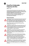
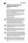
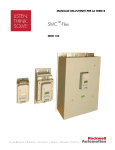
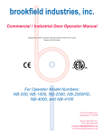
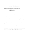
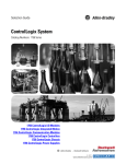
QUICK START
SMC™ FLEX
BULLETIN 150
This guide provides you with the basic information required to start up your SMC Flex controller. When reading
this document, look for this symbol “Step x” to guide you through the four basic steps required to install, start-up,
and program the SMC Flex.
The information provided in this Quick Start guide does not replace the User Manual which can be ordered or
downloaded by visiting www.ab.com. The Quick Start guide assumes the installer is a qualified person with
previous experience and basic understanding of electrical terminology, configuration procedures, required
equipment, and safety precautions.
For safety of maintenance personnel as well as others who might be exposed to electrical hazards associated with
maintenance activities, follow all local safety related work practices (for example, the NFPA 70E, Part II in the
United States). Maintenance personnel must be trained in the safety practices, procedures, and requirements that
pertain to their respective job assignments.
For detailed SMC Flex information including set-up, programming, precautions, and application considerations,
refer to the following documentation.
Title
Publication Number
Availability
SMC Flex User Manual
150-UM008*
www.ab.com/literature
SMC Flex Application Guide
150-AT002*
www.ab.com/literature
For product technical support:
Online Support
www.ab.com/support
Telephone Support
440-646-5800 (option 2, option 4 or use
direct dial code 804)
6 / 2011
www.klinkmann.com
6 / 2011
2
SMC™ Flex Quick Start
www.klinkmann.com
Step 1 - Read the General Precautions
!
WARNING
•
Only personnel familiar with the controller and associated machinery should plan or implement the
installation, start-up, and subsequent maintenance of the system. Failure to do this may result in personal injury
and/or equipment damage.
•
Hazardous voltage is present in the motor circuit even when the SMC-Flex controller is off. To avoid shock
hazard, disconnect main power before working on the controller, motor, and control devices such as Start-Stop
push buttons. Procedures that require parts of the equipment to be energized during troubleshooting, testing,
etc., must be performed by properly qualified personnel, using appropriate local safety work practices and
precautionary measures.
•
Failure of solid state power switching components can cause overheating due to a single-phase condition in the
motor. To prevent injury or equipment damage, the use of an isolation contactor or shunt trip type circuit
breaker on the line side of the SMC is recommended. This device should be capable of interrupting the motor’s
lock rotor current.
•
Hazardous voltages that can cause shock, burn, or death are present on L1, L2, L3, T1, T2, T3, T4, T5, and T6.
Power terminal covers for units rated 108…480 A can be installed to prevent inadvertent contact with
terminals. Disconnect the main power before servicing the motor controller, motor, or associated wiring.
6 / 2011
www.klinkmann.com
SMC™ Flex Quick Start
3
NOTICE
•
The controller contains ESD- (electrostatic discharge) sensitive parts and assemblies. Static control precautions
are required when installing, testing, servicing, or repairing the assembly. Component damage may result if
ESD control procedures are not followed. If you are not familiar with static control procedures, refer to
applicable ESD protection handbooks.
•
Stopping modes are not intended to be used as an emergency stop. The user is responsible for determining
which stopping mode is best suited to the application. Refer to the applicable standards for emergency stop
requirements.
•
Pump Stopping may cause motor heating depending on the mechanical dynamics of the pumping system.
Therefore, select the lowest stopping time setting that will satisfactorily stop the pump.
•
Slow Speed running is not intended for continuous operation due to reduced motor cooling.
•
The fan jumpers have been factory installed for 110/120V AC input. Refer to page 9 for 220/240V AC fan
wiring (5…480 A devices only).
•
Two peripheral devices can be connected to the DPI port. The maximum output current through the DPI port is
280 mA.
•
When installing or inspecting protective modules, make sure that the controller has been disconnected from the
power source. The protective module should be inspected periodically for damage or discoloration. Replace if
necessary.
•
An incorrectly applied or installed controller can damage components or reduce product life. Wiring or
application errors such as under sizing the motor, over sizing the controller, incorrect or inadequate AC supply,
excessive ambient temperatures, or power quality may result in malfunction of the system.
•
The Motor Overload parameter must be programmed by the installer to provide proper protection. Overload
configuration must be properly coordinated with the motor.
•
This product has been designed and tested as Class A equipment for EMC compatibility. Use of the product in
domestic environments may cause radio interference, in which case, the installer may need to employ
additional mitigation methods.
•
Disconnect the controller from the motor before measuring insulation resistance (IR) of the motor windings.
Voltages used for insulation resistance testing can cause SCR failure. Do not make any measurements on the
controller with an Insulation Resistance (IR or Megger) tester.
6 / 2011
4
www.klinkmann.com
SMC™ Flex Quick Start
Step 2 - Installation
Mounting
Enclosure Ratings
Standard Device Rating
IP00 (NEMA Open Type)
Minimum Required Enclosure
IP23 (NEMA Type 1)
Recommended Enclosure
IP54 (NEMA Type 12), sizing guide in User Manual
Enclosure Internal Temperature
-5…50 °C (23…122 °F)
Orientation and Clearance
Mounting Orientation
Vertical
Minimum horizontal clearance
0 cm (0 in.)
Minimum vertical clearance
15 cm (6 in.)
Controllers rated 625…1250 A
Device must be lifted only at the designated lift points identified with labels.
Lifting Points
6 / 2011
www.klinkmann.com
SMC™ Flex Quick Start
Dimensions
For detailed dimensions, please refer to the SMC Flex User Manual.
A
C
B
Lang
Esc
Sel
SMC-Flex TM
23 24 25 26 27 28 29 30 31 32 33 34
11 12 13 14 15 16 17 18 19 20 21 22
Dimensions are in millimeters (inches).
Controller Rating [A]
Height (B)
Width (A)
Depth (C)
Approximate Shipping
Weight
5…85
321.0 (12.60)
150.0 (5.90)
203.0 (8.00)
5.7 kg (12.5 lb)
108…135
443.7 (17.47)
196.4 (7.74)
212.2 (8.35)
15.0 kg (33.0 lb)
201…251
560.0 (22.05)
225.0 (8.86)
253.8 (9.99)
30.4 kg (67.0 lb)
317…480
600.0 (23.62)
290.0 (11.42)
276.5 (10.89)
45.8 kg (101 lb)
625…780
1041.1 (41.00)
596.9 (23.50)
346.2 (13.63)
179 kg (395 lb)
970…1250
1041.1 (41.00)
596.9 (23.50)
346.2 (13.63)
224 kg (495 lb)
5
6 / 2011
6
www.klinkmann.com
SMC™ Flex Quick Start
Power Wiring
Refer to the product nameplate or the SMC Flex User Manual for device specific information.
SMC Rating
[A]
Lug Kit
Cat. No.
Wire Strip
Length
Conductor
Range
5…85
—
18…20 mm
2.5…85 mm2
(#14…3/0 AWG)
—
—
108…135
199-LF1
18…20 mm
16…120 mm2
(#6…250 MCM)
1
1
31 N•m
(275 lb•in)
23 N•m
(200 lb•in)
201…251
199-LF1
18…20 mm
16…120 mm2
(#6…250 MCM)
2
2
31 N•m
(275 lb•in)
23 N•m
(200 lb•in)
317…480
199-LG1
18…25 mm
25…240 mm2
(#4…500 MCM)
2
2
42 N•m
(375 lb•in)
28 N•m
(250 lb•in)
625…780
100-DL630
32 mm/64 mm
70…240 mm2
(2/0…500 MCM)
2
2
45 N•m
(400 lb•in)
68 N•m
(600 lb•in)
970
100-DL860
26 mm/48 mm
120…240 mm2
(4/0…500 MCM)
1
1
45 N•m
(400 lb•in)
68 N•m
(600 lb•in)
100-DL630
32 mm/64 mm
70…240 mm2
(2/0…500 MCM)
1
1
26 mm/48 mm
120…240 mm2
(4/0…500 MCM)
1
1
45 N•m
(400 lb•in)
68 N•m
(600 lb•in)
1250
100-DL860
Max. No. Lugs/Pole
Line Side
Load Side
Tightening Torque
Wire - Lug
Lug - Busbar
11.3 N•m
—
(100 lb•in)
Control Terminals
23 24 25
26 27 28
29 30 31
32 33 34
11 12 13
14 15 16
17 18 19
20 21 22
Terminal
11➂➃
12➂➃
13➀
14
15➀➂
16➀➂
17➀➂
18➀➂
19➁➂
20➁➂
21
22
Description
Control Power Input (+)
Control Power Common
Controller Enable Input
Ground
Option Input #2
Option Input #1
Start Input
Stop Input
Aux Contact #1
Aux Contact #1
Not Used
Not Used
Terminal
23➀
24➀
25
26
27➀
28➀
29➁➂
30➁➂
31➁➂
32➁➂
33➁➂
34➁➂
Description
PTC Input
PTC Input
Tachometer Input
Tachometer Input
Ground Fault Transformer Input
Ground Fault Transformer Input
Aux Contact #2
Aux Contact #2
Aux Contact #3
Aux Contact #3
Aux Contact #4
Aux Contact #4
Footnotes
➀
Do not connect any additional loads to these
terminals. These “parasitic” loads may cause
incorrect operation.
➁
When set for External Bypass mode, the SMC
Flex can be used to control a properly sized
external contactor and overload once the motor
reaches full speed. The SMC-Flex overload
functionality is disabled in this mode.
➂
RC Snubbers are required on inductive type
loads connected to auxiliary contacts.
➃
Control power on units rated 625…1250 A is
pre-wired internally, from terminal block CP1.
6 / 2011
www.klinkmann.com
SMC™ Flex Quick Start
Control Wiring
Refer to the product nameplate for additional details. Depending on the specific application, additional control
circuit transformer VA capacity may be required.
Controllers rated 5…480 A
Control power is connected to the product through terminals 11 and 12.
Conductor Range
0.75…2.5 mm2 (18…14 AWG)
Torque
0.6 N•m (5 lb•in)
Maximum Number of Wires per Terminal
AC Control Voltage Input
2
100…240V AC or 24V AC (+10/-15%)
Supply Type
1-phase, 50/60 Hz
24V AC Power Requirement
130VA
100…240V AC Power Requirement
75VA
DC Control Voltage Input
24V DC (+10/-15%)
Inrush Current
Inrush Time
5A
250 ms
Transient Watts
60 W
Transient Time
500 ms
Staedy State Watts
Recommended Supply
Fan Power Input (AC only)
24 W
1606-XLP50E
separately wired
F5…F135
20VA
F201…F251
40VA
F317…F480
60VA
Controllers rated 625…1250 A
Control power is connected to the product through terminal block CP1, at terminals 1 and 4.
Conductor Range
Torque
Maximum Number of Wires per Terminal
Control Voltage Input
Supply Type
Control Power Input
0.75…2.5 mm2 (18…14 AWG)
0.6 N•m (5 lb•in)
2
110/120V AC or 230/240V AC, (+10/-15%)
1-phase, 50/60 Hz
800VA (includes controller, bypass, and fans)
7
6 / 2011
8
www.klinkmann.com
SMC™ Flex Quick Start
Typical Wiring Diagrams
Typical Power Wiring Examples
Diagrams per NEMA Symbology
Line Connection with
Isolation Contactor
(Default Mode)
L1
L2
Delta Connection with
Isolation Contactor
(Optional Mode)
L3
K1
L1
L2
Delta Connection with
Shorted SCR Protection
(Optional Mode)
L3
L1
L2
L3
K1
T5
T4
T6
K1
T1
T2
T3
T1
T2
T3
Motor
T1
T2
T6 T4 T5
T3
Motor
Motor
Diagrams per IEC Symbology
Line Connection with
Isolation Contactor
(Default Mode)
L1
L2
Delta Connection with
Isolation Contactor
(Optional Mode)
L1
L3
1
3
5
2
4
1
2
L2
L3
Delta Connection with
Shorted SCR Protection
(Optional Mode)
L1
L2
L3
1
3
5
1
3
5
6
2
4
6
2
4
6
3
5
1
3
5
4
6
2
4
6
1
3
5
K1
K1
V2
U2
W2
1
3
5
1
3
5
1
3
5
K1
2
4
V
2
U
M
3
6
W
2
U1
4
V1
6
W1
M
3
2
U1
4
V1
4
6
6
W1
M
3
W2
U2
V2
6 / 2011
www.klinkmann.com
SMC™ Flex Quick Start
Typical Control Wiring Examples
Fig 1.x
2 Wire Control (No DPI control or Option Stopping) with Fault Indication
L1 (L+)
Fan Power Terminations Example
(Separately Wired for F5...F480 Devices)
Programming Notes:
Aux#4 – Set for Fault
Parameter#132 – Set for Diable
2 Wire
Device
Factory Default Position
110/120 VAC
1
2
3
4
FAN
Supply
Jumpers
11
12
13
14 15
16
17 18
Hold In
Aux#2
23
1
2
3
4
24 25 26
27
Jumper
Fig 1.x
3 Wire Control (With or Without DPI control), Isolation Contactor (K1),
and Up-to-Speed Indication
L1 (L+)
Programming Notes:
Aux#1 – Set for Normal
Aux#4 – Set for Up to Speed
Stop
Start
Connection Required
for DPI Control
FAN
12
13
14 15
16
17
18
Hold In
19
20
21 22
Aux#1
SMC Flex Control Terminals
Aux#2
23
24 25 26
27
28 29 30
Aux#3
K1
Aux#4
31 32 33 34
A1
A2
Up-to-Speed
Indication
N (L-)
21 22
28 29 30
Aux#3
Aux#4
31 32 33 34
Fault
Indication
N (L-)
11
20
Aux#1
SMC Flex Control Terminals
Optional Configuration
220/240 VAC
Supply
19
9
6 / 2011
10
www.klinkmann.com
SMC™ Flex Quick Start
Typical Control Wiring Examples, Continued
Fig 1.x
3 Wire Control with Option Stopping, DPI control, Isolation Contactor (K1),
and Alarm Indication
L1 (L+)
Stop
Programming Notes:
Aux#1 – Set for Normal
Aux#4 – Set fot Alarm
Option Stop
Start
FAN
11
12
13
14 15
16
17 18
Hold In
19
20
21 22
Aux#1
SMC Flex Control Terminals
Aux#2
23
24 25 26
27
28 29 30
Aux#3
K1
Aux#4
31 32 33 34
A1
A2
Alarm
Indication
N (L-)
Fig 1.x
Start and Stop Control via DPI Communication ONLY with Isolation
Contactor (K1)
L1 (L+)
Programming Notes:
Aux#1 – Set for Normal
Parameter
#87 - Logic Mask must be set for DPI Control.
- Value of 4 enables HIM control only
- Value of 32 enables Communication Port control only
- Value of 44 enables ALL DPI ports for control
FAN
11
12
13
14 15
16
17 18
Hold In
19
20
21 22
Aux#1
SMC Flex Control Terminals
Aux#2
23
N (L-)
24 25 26
27
28 29 30
Aux#3
Aux#4
31 32 33 34
K1
A1
A2
6 / 2011
www.klinkmann.com
SMC™ Flex Quick Start
Step 3 - Basic Programming
The SMC-Flex controller can be programmed with the built-in keypad and LCD display or with an optional
Bulletin 20-HIM-xx LCD human interface module.
Menu Structure Hierarchy
Main Menu
Parameters
See File Structure Below for
additional details
Diagnostics
Alarms
Faults
Device Revision
Preferences
Change Password
User Dspl Line
User Dspl Time
User Dspl Video
Reset User Display
Power Up and Status Display
---
Stopped
0.0 Amps
0.0 Volt
0.0 %MTU
Memory
Storage
Reset to Defaults
Enter Password
Log In *
(* - Only Active when a password is used)
Monitoring
Metering
Volts Phase A-B
Volts Phase B-C
Volts Phase C-A
Current Phase A
Current Phase B
Current Phase C
Watt Meter
Kilowatt Hours
Elapsed Time
Meter Reset
Power Factor
Mtr Thermal Usage
Set Up
Basic
SMC Option
Motor Connection
Line Voltage
Starting Mode
Ramp Time
Initial Torque
Cur Limit Lvl
Kickstart Time
Kickstart Level
Stop Input
Option 1 Input
Option 2 Input
Stop Mode
Stop Time
Overload Class
Service Factor
Motor FLC
Overload Reset
Aux1 Config
Aux2 Config
Aux3 Config
Aux4 Config
Parameter Mgt
Motor Protection
Overload
Overload Class
Service Factor
Motor FLC
Overload Reset
Overload A Lvl
Parameter Mgmt
Jam
Jam F Lvl
Jam F Dly
Jam A Lvl
Jam A Dly
Parameter Mgmt
Stall
Underload
Underload F Lvl
Underload F Dly
Underload A Lvl
Underload A Dly
Parameter Mgmt
Undervoltage
Undervoltage F Lvl
Undervoltage F Dly
Undervoltage A Lvl
Undervoltage A Dly
Parameter Mgmt
Stall Delay
Parameter Mgmt
Ground Fault
Gnd Flt Enable
Gnd Flt Lvl
Gnd Flt Dly
Gnd Flt Inh Time
Gnd Flt A Enable
Gnd Flt A Lvl
Gnd Flt A Dly
Parameter Mgmt
Communications
Utility
Linear List
Comm Masks
Language
Linear List
Logic Mask
Parameter Mgmt
Data Links
Data In A1
Data In A2
Data In B1
Data In B2
Data In C1
Data In C2
Data In D1
Data In D2
Data Out A1
Data Out A2
Data Out B1
Data Out B2
Data Out C1
Data Out C2
Data Out D1
Data Out D2
Parameter Mgmt
Language
Parameter Mgmt
All Parameters
Motor Data
Motor FLC
Motor ID
Parameter Mgmt
PTC
Overvoltage
Overvoltage F Lvl
Overvoltage F Dly
Overvoltage A Lvl
Overvoltage A Dly
Parameter Mgmt
PTC Enable
Parameter Mgmt
Phase Reversal
Phase Reversal
Parameter Mgmt
Unbalance
Restart
Unbalance F Lvl
Unbalance F Dly
Unbalance A Lvl
Unbalance A Dly
Parameter Mgmt
Starts Per Hour
Restart Attempts
Restart Delay
Parameter Mgmt
Note:
•Depending on the SMC option, additional
parameters may appear in some menus
•The external HIM has similar programming
operation to the built-in HIM, however some
differences do exist.
•The built-in HIM can not be used to program
other DPI devices (i.e. Device Select)
11
6 / 2011
12
www.klinkmann.com
SMC™ Flex Quick Start
Access the Basic set up group by selecting the Parameters menu from the Main Menu and then Set Up.This
programming group provides a limited parameter set, allowing quick start-up with minimal adjustment.
Parameter Name and Description
Values
Default
Parameter # 14 - SMC Option
Displays the type of controller. This is factory set and not adjustable.
Standard, Pump Control, Brake
Read Only
Parameter # 15 - Motor Connection
Displays the motor type to which the device is being connected.
Line or Delta
Line
Parameter # 16 - Line Voltage
Displays the system line voltage to which the unit is connected.
0…10000
480
Parameter # 17 - Starting Mode
Allows the user to program the SMC-Flex controller for the type of starting that best fits the application.
Soft Start, Current Limit, Full
Voltage, Linear Speed, Pump
Control
Soft Start
Parameter # 18 - Ramp Time
This sets the time period during which the controller will ramp the output voltage.
0…30 s
10
Parameter # 19 - Initial Torque
When the Soft Start mode is selected, this parameter sets the initial reduced voltage output level for the
voltage ramp.
0…90% of locked rotor torque
70
Parameter # 20 - Current Limit Level
When Current Limit mode is selected, this parameters sets level of current that is applied for the
programmed Ramp Time.
50…600% FLC
350
Parameter # 22 - Kickstart Time
A boost current is provided to the motor for the programmed time period.
0.0…2.0 s
0
Parameter # 23 - Kickstart Level
Adjusts the amount of current applied to the motor during kickstart.
0…90% of locked rotor torque
0
Parameter # 133 - Stop Input
Allows the user to select the operation of terminal 18, Stop Input.
Coast, Stop Option
Coast
Parameter # 132 - Option Input 1
Allows the user to select the operation of terminal 16, Option Input #1.
Disable, Coast, Stop Option,
Fault, Fault NC, Network
Stop Option
Parameter # 24 - Option Input 2
Allows the user to select the operation of terminal 15, Option Input #2.
Disable, Slow Speed, Dual Ramp,
Fault, Fault NC, Network, Clear
Fault
Disable
Parameter # 32 - Stop Mode
Allows the user to program the SMC Flex controller for the type of stopping that best fits the application.
Soft Stop, Linear Speed, SMB,
Accu-Stop, Pump Stop
Soft Stop
Parameter # 33 - Stop Time
This sets the time period which the controller will ramp the voltage during a stopping maneuver.
0.0…120 s
0.0
Parameter # 44 - Overload Class
Allows the user to enter the desired Overload trip class for the motor.
Disable, 10, 15, 20, 30
10
Parameter # 45 - Service Factor Allows the user to enter the Service Factor of the motor. For IEC motors the typical value is 1.0. For NEMA
0.01…1.99
1.15
Parameter # 46 - Motor FLC This is a user entered value that is needed so the device can provide proper motor Overload protection.
1.0…2200
1.0
Parameter # 47 - OL Reset Mode This value allows the user to define how the overload can reset.
Auto, Manual
Manual
Parameter # 107 - Aux1 Config
Auxiliary 1 contact is located at terminals 19 and 20 and allows the user to configure the operation of the
contact.
Normal, Up-to-speed, Fault,
Alarm, Network Control, External
Bypass: (N.O./N.C.)
Normal
Parameter # 110 - Aux2 Config
Auxiliary 2 contact is located at terminals 29 and 30 and allows the user to configure the operation of the
contact.
Normal, Up-to-speed, Fault,
Alarm, Network Control, External
Bypass: (N.O./N.C.)
Fault
Parameter # 108 - Aux3 Config
Auxiliary 3 contact is located at terminals 31 and 32 and allows the user to configure the operation of the
contact.
Normal, Up-to-speed, Fault,
Alarm, Network Control, External
Bypass: (N.O./N.C.)
Alarm
Parameter # 109 - Aux4 Config
Auxiliary 4 contact is located at terminals 33 and 34 and allows the user to configure the operation of the
contact.
Normal, Up-to-speed, Fault,
Alarm, Network Control, External
Bypass: (N.O./N.C.)
Normal
Parameter # 115 - Parameter Mgmt
Allows the user the ability to recall all Factory default parameter values.
Ready, Load Default
Ready
6 / 2011
www.klinkmann.com
SMC™ Flex Quick Start
13
Step 4 - Operation and Troubleshooting
Start Up Check List
1.
2.
3.
4.
5.
Verify Input Supply voltage and wiring
Check output wiring
Check control wiring
Apply control power
Test local start/stop control
Monitoring
The SMC Flex controller has built in diagnostics and metering functions which can be accessed through a local or
remote LCD display.
Step
Action
1
From any menu, Press Esc to get to the MAIN Device display.
2
If using the built in display, Press Enter and continue to step #3.
If using a remote HIM, first make sure that the SMC Flex is displayed by going to
MAIN MENU / DEVICE SELECT / SMC FLEX Press Enter and continue to step #3.
3
To View or Review the Metering Information
- Access the metering parameters by selecting PARAMETER / MONITORING / and then METERING. Press enter to view
any selected value.
Viewing and Clearing Faults
Step
Action
1
Press Esc to acknowledge the fault. The fault information will be removed so that you can use the HIM.
2
To View or Review the fault information
- Go to MAIN MENU / DIAGNOSTICS / FAULTS / VIEW FAULT QUEUE.
- Or look at parameters 124…128.
3
Address the condition that caused the fault. The cause must be corrected before the fault can be cleared.
4
After corrective action has been taken, clear the fault by one of these methods:
- Press and Hold the ESC key for 3 seconds.
- Cycle control power to the device.
- Press Stop key on an External HIM.
- Program the SMC-Flex controller for a CLEAR FAULT, which can be found in MAIN MENU / DIAGNOSTICS / FAULTS.
- Option Input #2 (terminal 15) can be configured to clear faults with the use of N.O. push button.
6 / 2011
14
www.klinkmann.com
SMC™ Flex Quick Start
Troubleshooting - Abbreviated Listing
For a complete list of fault codes and troubleshooting tips, refer to the SMC Flex User Manual.
Display Fault Fault Code
Enabled
Line Fault with
Phase Indication
1, 2, 3
prestart
only
Shorted SCR
with Phase
indication
4, 5, 6
all
Open Gate with
Phase Indication
7, 8, 9
start or
stop
PTC Power Pole
and SCR
Overtemp
10, 11
Motor PTC
Possible Causes
Possible Solutions
Missing supply phase
Motor not connected properly
Incoming 3-phase voltage instability
Check for open line (i.e., blown fuse)
Check for open load lead
Verify power quality
Shorted power module
Check for shorted SCR, replace power module if necessary
Open gate circuitry
Loose gate lead
Perform resistance check; replace power module if necessary
Check gate lead connections to the control module
Controller ventilation blocked
Controller duty cycle exceeded
Fan failure
Ambient temperature limit exceeded
Failed thermistor
Check for proper ventilation
Check application duty cycle
Wait for motor to cool or provide external cooling
Replace power module or control module as needed
Replace fan
12
running
Motor ventilation blocked
Motor duty cycle exceeded
PTC open or shorted
Check for proper ventilation
Check application duty cycle
Wait for motor to cool or provide external cooling
Check resistance of PTC
Open Bypass
with phase
indication
13, 14, 15
running
Control voltage is low
Inoperable power module bypass
Check control voltage power supply
Replace power module
Check control module TB2…TB4 and TB5…TB7 for securness
Check Aux 1, 2, 3, 4 configurations are not set to External
Bypass
No Load Fault
16, 17, 18, 40
prestart
only
Loss of load side power wiring
Start command cycled unexpectedly with motor rotating
Check all load side power connections
Check motor windings
Line Unbalance
19
running
Supply unbalance is greater than the user-programmed value Check power system and correct if necessary
The delay time is too short for the application
Extend the delay time to match the application requirements
Overvoltage
20
running
Supply voltage is greater than user programmed value
The delay time is too short for the application
Check power system and correct if necessary
Correct the user-programmed value
Extend the delay time to match the application requirements
Undervoltage
21
running
Supply voltage is less than user programmed value
The delay time is too short for the application
Check power system and correct if necessary
Correct the user-programmed value
Extend the delay time to match the application requirements
Overload
22
running
Motor overloaded
Overload parameters are not matched to the motor
Check motor overload condition
Check values for overload class and motor FLC
Verify current draw of the motor
Underload
23
running
Broken motor shaft, belts, toolbits, etc..
Pump cavitation
Incorrect user setting
Check pump system, machine drive components, and loading
Check settings
Repair or replace motor
Jam
24
running
Motor current has exceeded the user programmed jam level
Correct source of jam or excessive loading
Check programmed time value
Stall
25
running
Motor did not reach full speed by the end of the programmed
ramp time
Incorrect user setting
Correct source of stall or excessive loading
Adjust SMC starting parameters to compensate for load
Phase Reversal
26
prestart
only
Incoming supply voltage is not in the expected ABC sequence
Check power wiring, correct if necessary
Network and
Comm's Loss
30, 31, 32
27, 28, 29
all
DPI network loss
Communication disconnection at the serial port
Check communication adapters and verify connection to SMC
Reconnect each DPI connected device
Ground Fault
33
running
Ground fault current level has exceeded programmed value
The delay time is too short for the application
Check power system and motor; correct if necessary
Check programmed ground fault levels to match application
requirements
Extend the delay time to match the application requirements
Power Loss with
phase indication
35, 36, 37
start or
stop
Missing supply phase (as indicated)
Internal CT problem
Check for open line (i.e., blown line fuse)
Replace power pole as indicated
Line Loss with
phase indication
41, 42, 43
start or
stop
Incoming 3-phase voltage instability or distortion
High impedance connection
Check supply voltage for capability to start/stop motor
Check for loose connections on line side or motor side of
power wires
Verify and correct input power quality
Internal 24V and
System Faults
44, 45, 46,
128…209
all
Low line condition
Excessive load on
Check the control power, verify it is within the specification
Check connections and grounding to the SMC control
terminals
Replace control module
Repair Parts
Part No. ➀
Description
Control Modules
SMC Rating
Standard
Pump
Braking
100…240V AC
41391-454-01-S1FX
41391-454-01-B1FX
41391-454-01-D1AX
41391-454-01-D1BX
41391-454-01-D1CX
41391-454-01-D1DX
41391-454-01-D1EX
All
All
5…85 A
108…251 A
317…480 A
625…780 A
970…1250 A
24V AC/DC
41391-454-02-S2FX
41391-454-02-B2FX
41391-454-02-D2AX
41391-454-02-D2BX
41391-454-02-D2CX
N/A
N/A
Part No. ➀
Description
SMC Rating
Series
Power Poles
5A
25 A
43 A
60 A
85 A
108 A
135 A
108 A
135 A
201 A
251 A
317 A
361 A
480 A
625 A
780 A
970 A
1250 A
5…85 A
108…135 A
201…251 A
317…480 A
625…1250 A
B
B
B
B
B
A
A
B
B
B
B
B
B
B
B
B
B
B
B
B
B
B
B
625…1250 A
B
41391-801-05
201…251 A
317…480 A
625…780 A
970…1250 A
625…780 A
970…1250 A
B
B
B
B
B
B
41391-803-01
41391-803-02
100-D180ED11
100-D420ED11
100-D180EA11
100-D420EA11
Heatsink Fans
110/120V AC
Control Power
230/240V AC
Control Power
Base Plate
By-Pass
Contactor ➃
➀
➁
➂
➃
For units rated 690V
AC
For units rated 200…600V AC
110/120V AC
Control Power
230/240V AC
Control Power
100…240V AC
41391-454-05-S1FZ
41391-454-05-B1FZ
41391-454-05-D1AZ
41391-454-05-D1BZ
41391-454-05-D1CZ
41391-454-05-D1DZ
41391-454-05-D1EZ
Line Voltage
200…480V
150-FPP5B ➁
150-FPP25B ➁
150-FPP43B ➁
150-FPP60B ➁
150-FPP85B ➁
41391-800-01 ➂
41391-800-03 ➂
150-FPP108B ➁
150-FPP135B ➁
150-FPP201B
150-FPP251B
150-FPP317B
150-FPP361B
150-FPP480B
150-FPP625B
150-FPP780B
150-FPP970B
150-FPP1250B
200…600V
150-FPP5C ➁
150-FPP25C ➁
150-FPP43C ➁
150-FPP60C ➁
150-FPP85C ➁
41391-800-02 ➂
41391-800-04 ➂
150-FPP108C ➁
150-FPP135C ➁
150-FPP201C
150-FPP251C
150-FPP317C
150-FPP361C
150-FPP480C
150-FPP625C
150-FPP780C
150-FPP970C
150-FPP1250C
41391-801-03
41391-801-03
41391-801-01
41391-801-02
41391-801-04
230…690V
N/A
N/A
N/A
N/A
N/A
N/A
N/A
150-FPP108Z ➁
150-FPP135Z ➁
150-FPP201Z ➂
150-FPP251Z ➂
150-FPP317Z ➂
150-FPP361Z ➂
150-FPP480Z ➂
150-FPP625Z ➂
150-FPP780Z ➂
150-FPP970Z ➂
150-FPP1250Z ➂
One piece provided per part number.
Three-phase power pole structure provided per part no.
One-phase power pole provided per part no.
Refer to Appendix D in the SMC Flex User Manual, for installation instructions.
Publication 150-QS001G-EN-P — August 2008
Superecedes Publication 150-QS001F-EN-P — November 2006
40055-217-01 (7)
Copyright ©2008 Rockwell Automation, Inc. All Rights Reserved. Printed in USA.
Rockwell_Power_Soft_Starters_SMC_Flex_Quick_Start_en_0611.pdf
Helsinki
St. Petersburg
Moscow
tel. +358 9 540 4940
automation@klinkmann.fi
tel. +7 812 327 3752
[email protected]
tel. +7 495 641 1616
[email protected]
Yekaterinburg
Samara
Кiev
tel. +7 343 376 5393
[email protected]
tel. +7 846 273 95 85
[email protected]
tel. +38 044 495 33 40
[email protected]
Riga
Vilnius
Tallinn
Мinsk
tel. +371 6738 1617
[email protected]
tel. +370 5 215 1646
[email protected]
tel. +372 668 4500
[email protected]
tel. +375 17 200 0876
[email protected]
www.klinkmann.com