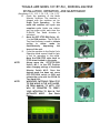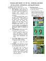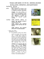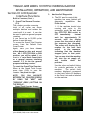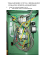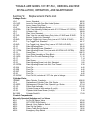
1
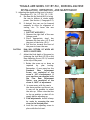
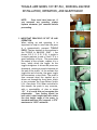
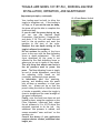
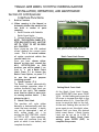
AUTOMATED INDUSTRIAL MACHINE, INC. JORACOTOGGLE-AIRE DIVISION 347 Farnum Pike Smithfield, RI, USA 02917 401-232-1710 www.joraco.com Installation, Operation and Maintenance 3 & 5 Ton, 1011RT PLC Series Rotary Indexing Machine IMPORTANT It is the responsibility of the employer/purchaser to provide his or her employees with proper point of operation guards, and to insure that this equipment is used in accordance with the manufacturer's recommendations as well as any OSHA, federal, or state regulations that are applicable to such equipment. Because it is impossible to anticipate the conditions under which our equipment will be operated, additional safety devices and methods may be required to insure operator safety. Besides conforming to all federal, state, and local codes, the buyer should consider the safety of the entire operation involving any press, and see that any additional guarding, training, and maintenance deemed necessary is developed and enforced to protect the well being of the operator. THINK SAFETY . . . . . .WORK SAFELY COPYRIGHT 2005 by Automated Industrial Machine, Inc. Joraco Division Smithfield, RI, USA All rights reserved TOGGLE-AIRE MODEL 1011RT-PLC, INDEXING MACHINE INSTALLATION, OPERATION, AND MAINTENANCE Section I: Installation 1. Carefully remove the crating material from around the 1011RT. Leave the pallet the unit was shipped on intact, with the machine bolted to it. Lift the pallet with a pallet truck or forklift to carefully move the machine to the place it will be installed. (See photo 1.1) NOTE: Always use extreme care when moving the machine. Support the unit properly. Do not allow the machine to lean or flip while moving. 2. Remove the 1011RT from the pallet. (See photos 1.2, 1.3, 1.4, 1.5) A. Remove the carriage bolts that hold the machine to the shipping pallet. B. Use a forklift or similar lifting device to lift the Model 1011RT up and off the shipping pallet. Note the location of the forks under the lower cross members of the machine base. Lift off the pallet in this manner only. C. If your machine was supplied with leveling feet, install them in the pads at the bottom of each of the four legs at this time. D. Carefully move and lower the machine into the final installation position. 1. If you are using leveling feet, adjust them as necessary to keep the 1011RT plumb and leveled in all directions. Lock them in position to prevent accidental changes. 2. If you are permanently installing the unit, use the holes in the pads at the bottom of each leg to bolt the machine to the floor using appropriate fasteners for your flooring system. Use shims if necessary to make up for variations in your floor surface. Photo 1.1 Photo 1.2 Photo 1.3 Photo 1.4 Photo 1.5 NOTE: If desired, the front cross member may be removed after installation. Remove the valving cover to access the bolts. Replace cover when finished. TOGGLE-AIRE MODEL 1011RT-PLC, INDEXING MACHINE INSTALLATION, OPERATION, AND MAINTENANCE CAUTION: WHENEVER CONNECTING YOUR AIR AND ELECTRICAL SUPPLY TO THE MACHINE BE CERTAIN TO FOLLOW SAFE OPERATING PROCEDURES AND KEEP ALL PARTS OF YOUR BODY AWAY FROM THE MOVING PARTS OF THE PRESS, INDEXING UNIT, AND ANY TOOLING INSTALLED! 3. Connect air supply. (See photos 1.6, 1.7, 1.8, 1.9) NOTE: Before proceeding check the position of the MS-1, OFF-STOP-RUN Switch. Move the switch to STOP if it is not already in that position. The air supply must be clean and conditioned. Use of the Filter, Regulator, Lubricator Unit supplied with your 1011RT is crucial. For optimum results all air lines, fittings, and hoses used to supply the indexing machine should be the equivalent of 1/2" NPT minimum ID. B. The minimum air pressure for operation is 70 PSI. The maximum is 125 PSI. The optimum operating range is 80 to 100 PSI. If your application consistently requires substantially more than 100 PSI it may indicate the need for a stronger press. C. Connect the air supply to the Model 1011RT at the inlet port on Part No. MV-1, Air Supply On-Off Sleeve Valve. Plug the machine’s power cord into a standard 110 VAC grounded receptacle. Photo 1.6 A. NOTE: A three way Shut Off Valve like the one supplied must always be used to insure complete bleeding of the press circuits when air supply is off. Photo 1.7 Photo 1.8 Photo 1.9 Read and Understand Cautions on machine TOGGLE-AIRE MODEL 1011RT-PLC, INDEXING MACHINE INSTALLATION, OPERATION, AND MAINTENANCE 4. Turn on air supply. (See photos 1.10, 1.11 ) A. Remove the yellow lock out device found on the On-Off Valve. To turn the air on simply slide the gold colored sleeve to the right until it stops. Slide the sleeve to the left to the stop to shut the supply off. With the supply on, check for air leaks and be sure all connections you have made are secure and air tight. If air leaks from inside the "SynchroSig" actuator the connections are incorrect. Correctly reconnect the tubing, taking note of the tubing labels. NOTE: When the machine is not in use or being serviced or maintained, always SHUT OFF the air supply and replace the lockout device. Secure with a padlock, etc. to prevent unauthorized use of the machine. CAUTION: BEFORE PROCEEDING, CLEAR THE TOOLING PLATE AND WORK AREA OF ALL TOOLS, FOREIGN OBJECTS, AND BODY PARTS. Photo 1.12 Photo 1.10 Photo 1.11 Pictured to the lower left is the 1011RT PLC Control Panel. It contains the various mode selector switches used to control the operation of the machine, as well as one of the two Emergency Stop Switches and the LCD Operator Interface Panel ( see Section III ) which is used to set various production parameters. IMPORTANT: Once you have the machine set in the desired mode of operation move MS-1 OFFSTOP-RUN switch to RUN and initiate any and all cycles of the machine with the SS-DM-24 Two Hand Actuator. IF YOU DO NOT BEGIN TO CYCLE THE MACHINE WITHIN 30 SECONDS the machine's Self Diagnostic System (see Section III) interprets this as a fault. Simply use the MS-1 OFF-STOPRUN switch to RESET the machine. Start all cycles within 30 Seconds of moving the switch to RUN. TOGGLE-AIRE MODEL 1011RT-PLC, INDEXING MACHINE INSTALLATION, OPERATION, AND MAINTENANCE (See photos 1.12, 1.13, 1.14, 1.15, 1.16, 1.17) B. Check the positions of the Mode Selector Switches. The machine is shipped with the switches set for Single Cycle Operation. In this mode the machine will cycle one complete cycle (index one station and one press cycle) each time the SS-DM-24 Two Hand Actuator is activated. C. Move the OFF-STOP-RUN Valve, MS1 to the RUN position. The SS-DM-24 Two Hand Actuator is used to initiate cycling in either mode by simultaneously depressing the levers of the unit. D. Cycle the machine in the Single Cycle Operation Mode several times to gain a feel for operation in this mode. Move the RUN-STOP valve back to STOP when finished in this mode. NOTE: Always move the OFF-STOP-RUN Switch, MS-1, to the OFF Position when changing settings of the Mode Selector Switch MS-2. Once the desired mode has been set, move OFF-STOP-RUN switch to RUN and initiate the cycle with the SS-DM-24 Two Hand Unit. NOTE: WHENEVER SWITCHING FROM STOP TO RUN WHILE IN THE AUTO MODE, OR FROM MANUAL TO AUTO, YOU WILL BE PROMPTED TO VERIFY YOUR INTENTION TO RUN IN THE AUTOMATIC MODE. (See Photo Below) Photo 1.13 Photo 1.14 Photo 1.15 Photo 1.16 Photo 1.17 TOGGLE-AIRE MODEL 1011RT-PLC, INDEXING MACHINE INSTALLATION, OPERATION, AND MAINTENANCE 5. Additional Controls and Features (See photos 1.18, 1.19, 1.20, 1.21, 1.22, 1.23) A. Machine Reset. If either one of the MS-5 Emergency Stop Switches is activated, or if the Ram Safety Guard is moved while the machine is running the machine will immediately stop and dump all air in the system. 1. To Reset the 1011RT simply move the MS-1 OFF-STOP-RUN Switch to the OFF position . The machine will be reset to the starting position. Trouble shoot the reason the machine was shut down prior to attempting to run again. If the Emergency Stop Switch was used you must reset it by rotating the switch in the direction indicated on the button prior to starting up again. B. Press Ram Speed Controls are located on the left side of the machine. 1. Adjust the metering screw in or out as necessary to adjust the press ram speed as desired. Always lock the adjusting screw in place after adjustments are made. C. Rotary Index Speed Control located on the index cylinder assembly. 1. Adjust the knob in or out as necessary to adjust the index speed. D. Emergency Stop Switches located on the control panel and the right end of the machine base plate. 1. Use either one of these to immediately stop the entire 1011RT should the need arise. All circuits are exhausted and dumped. Use the reset procedure (see 5A above) to reset the machine after use. G. Ram Safety Guard. Profile the halves of the guard to clear your tooling. 1. Center Guard on detent. If this guard is moved off the centered position the machine shuts down in the same manner as the Emergency Stops do. Trouble shoot problem, center the guard again, and follow reset procedure in 7A. Photo 1.18 Photo 1.19 Photo 1.20 Photo 1.21 TOGGLE-AIRE MODEL 1011RT-PLC, INDEXING MACHINE INSTALLATION, OPERATION, AND MAINTENANCE E. Ram Set Up Switch allows the tool setter to lock the press ram in the down position to facilitate the depth setting of your tooling. See Section II, Para. 2 and 3 for more information about depth setting. 1. The Ram Set Up Switch is only usable when the MS-1, OFF-STOPRUN switch is in the STOP position. 2. With the OFF-STOP-RUN switch in the OFF position, press MS-3, RAM SET UP switch in. The amber button will light and stay on. At this point, you must use the SSDM Two Hand Actuator to start the ram's down stroke. The ram will stay at the bottom of its stroke until the RAM SET UP SWITCH is pressed again. NOTE; THE RAM WILL NOT DESCEND UNLESS BOTH HALVES OF THE RAM SAFETY GUARD ARE IN PLACE. The Ram will, however, retract to the UP position up whether the guard halves are in place or not. 3. Once the ram descends the halves of the guard can be removed to allow work on the tooling. 4. The ram will stay in the down position until the MS-3 RAM SET UP switch is pressed again. F. Rotary Table Set Up Switch, MS-4. This switch allows the toolsetter to operate the indexing table without the press. This is useful during the tooling and set up phase of the installation. 1. With the MS-1, OFF-STOP-RUN switch in the STOP position, place the MS-4, Table Set Up Switch to TABLE ONLY. Use the SS-DM Two Hand Actuator to index to each station. NOTE: Ram Guard must be in place. When finished, move the switch to the NORMAL position Photo 1.22 Photo 1.23 TOGGLE-AIRE MODEL 1011RT-PLC, INDEXING MACHINE INSTALLATION, OPERATION, AND MAINTENANCE Section II: Set Up NOTE: CAUTION: (See photos 2.1, 2.2) When installing any tooling on the tooling plate, be sure proper point of operation guarding, specifically designed for your tooling, is installed on the machine at this time. If the standard Ram Safety Guard supplied is not suitable for your application, consult the factory for optional guards available. Photo 2.1 NEVER OPERATE, SERVICE, OR ADJUST THIS MACHINE WITHOUT PROPER INSTRUCTION. NEVER SERVICE THIS MACHINE WITHOUT FIRST SHUTTING OFF AIR SUPPLY. Photo 2.2 NEVER OPERATE THIS MACHINE WITH SAFETY GUARDS REMOVED. 1. Mount your tooling. (See photos 2.3, 2.4) A. For maximum accuracy each station should be located from the press ram. A simple way to locate the centers of each station relative to the ram is to mount an appropriate center punch in the press ram. You may need to turn an adaptor/holder to get the punch into the shut height range of the machine. Be sure the Ram Adjusting Screw JP-11 is adjusted up all the way. With the 1011RTPLC set in MANUAL Mode and Rotary Table in the NORMAL position, cycle the 1011RT once with the SS-DM-24 Actuator. The machine will cycle once. Adjust the Ram Adjusting Screw down until the punch marks the plate as necessary for your purposes. Continue to mark all stations in this manner. (See section VI, Para. C for more information) Photo 2.3 Photo 2.4 TOGGLE-AIRE MODEL 1011RT-PLC, INDEXING MACHINE INSTALLATION, OPERATION, AND MAINTENANCE 2. Adjusting the depth setting (end of stroke). (See photos 2.5, 2.6, 2.7, 2.8, 2.9, 2.10) A. Use Ram Set Up Switch MS-3 to bring the ram to bottom of stroke under power. (See Section I, Paragraph 5 E) B. If desired, the ram can be lowered manually to allow for alignment of tooling, etc. To lower the ram manually: 1. SHUT OFF AIR SUPPLY. 2. Remove the right half of the rear linkage guard. 3. Place appropriate steel bar between the ram yoke ( JP-7) and the pivot of the lever (JO-1). 4. Pull the bar towards the front of the press to lower the ram. CAUTION: RAM WILL RETURN UP WHEN AIR SUPPLY IS RESTORED. C. Adjust the final depth of the press by loosening the Lock Nut (JP-33) on the Ram Adjusting Screw (JP-11) located at the top of the press. 1. Rotate the screw up or down as required by your tooling. Remember, if your press has the Standard Ram Adjustment Screw, one revolution of the screw is .100" of adjustment. If your machine was supplied with the Fine Ram Adjustment Option, one revolution of the screw is .0625" of adjustment. Photo 2.5 Photo 2.6 Photo 2.7 2. In some cases, with the ram in the down position and the air on, it may not be possible to adjust the ram up. Either raise the ram to the up position or shut off air supply before adjusting up. 3. Final adjustments should always be made by screwing the ram down to the desired point. 4. Lock the ram adjusting screw in place with the lock nut. Photo 2.8 TOGGLE-AIRE MODEL 1011RT-PLC, INDEXING MACHINE INSTALLATION, OPERATION, AND MAINTENANCE NOTE: Once tools have been set, if you removed any guarding, always replace whatever you removed before proceeding. Photo 2.9 3. IMPORTANT PRINCIPLES OF SET UP AND OPERATION. When setting up and operating it is important to keep in mind that the press is a pneumatically powered TOGGLE PRESS. The key element in the machine is the TOGGLE or KNUCKLE JOINT. ( See photos 2.10, 2.11, 2.12, 2.13) A toggle is a simple machine in and of itself. It is a great multiplier of force. The press takes the output of the cylinder, couples it to a lever, which drives the toggle. As the toggle straightens it drives the press ram downward, creating a powerful squeeze at the end of the stroke. At the moment the toggle hits end of stroke, the upper toggle link encounters a stop block. The press is then reversed when the impulse pin is driven out through the front plate, which in turn actuates the Press Return Switch LS-4. (See photo 2.14) When controlled in this manner the press is very accurate, with a repeatability of plus or minus .001". It is crucial that you recognize this relationship. Your tooling should be built with a shut height that falls within the shut height range of the press. In standard machines this is approx. 4.570" maximum to 3.820" minimum. Photo 2.10 Photo 2.11 Photo 2.12 Photo 2.13 TOGGLE-AIRE MODEL 1011RT-PLC, INDEXING MACHINE INSTALLATION, OPERATION, AND MAINTENANCE (Important principles, continued) LS-4 Press Return Switch Your tooling must be built to allow the toggle to straighten out. If the tooling is too high, or if you set the ram too deep, the press will not be able to complete the stroke and stall. If you do stall the press during set up, you can use the Machine Reset Proceedure. ( See Section I, Paragraph 5A, and photo 2.15) This will send the ram back to the up position and reset the machine to the start of the cycle. Readjust the ram depth setting so the toggle is allowed to straighten. Do not confuse the nature of the force curve in the ram with the Ram Adjusting Screw or depth adjustment. The ram force developed by the press is not affected by the Ram Adjusting Screw or where you are set in terms of ram depth. The only thing that affects ram force is the air pressure used to power the press. The Ram Adjusting Screw is simply an end of stroke adjustment, much like the adjusting collar found on full revolution, mechanical power presses. In fabrication jobs like punching, piercing, and blanking enter the punch only as deep as necessary to clear your blank, etc. Always set up so that the press is doing the work as close to the end of stroke as possible, where the toggle is close to straight and the rated strength of the press is developed. Finally, once the tools have been set and locked in place, using the regulator on the Filter, Regulator, Lubricator Unit, adjust the air pressure to 5 to 10 PSI above the minimum required to do the job. Any additional line pressure is wasted, and causes unneeded "wear and tear" on the machine, etc. Consult the factory if your application requires shorter strokes, additional shut height, etc. Photo 2.14 Photo 2.15 TOGGLE-AIRE MODEL 1011RTPLC INDEXING MACHINE INSTALLATION, OPERATIION, AND MAINTENANCE Section III: LCD Operator Interface Functions 1. Built in Counters A. When running in the Manual or Automatic Modes the machine has two built in modes of parts counting. 1. Batch Counter with Settable Batch Count Limits 2. General Grand Total Counter NOTE: THE CONTROL PANEL OFFSTOP-RUN SWITCH MS-1 MUST BE SET TO "STOP" TO SET OR ZERO ALL COUNTERS. Upon power-up the LCD readout screen displays the current parts count. This is the actual number of cycles completed within the current batch run. Once you have chosen either Manual or Auto and moved the MS-1 OFF-STOP-RUN to RUN position, you will be asked if you want to a set a Batch Count Limit. Press F-1 to choose the Batch Count Option, or press F-3 to use the general purpose totalizing counter. 1. Batch Counter ( F-1) The Batch Counter automatically stops machine operation when it reaches the Batch Count Limit you have set (see right). This counter must then be reset to zero prior to running another batch. ( See photos to right ) 2. Batch Count Limit The machine will cycle either Manually or Automatically until this count has been reached. A batch run can be interrupted ( end of shift, coffee break, etc. ) by moving the OFF-STOP-RUN switch to STOP or OFF. Upon restarting, the count will continue from the point at which it was halted, and complete the batch. Default Total Parts Count Screen With control panel mode switch set to stop, press F3 to zero the parts counter. Batch Count Limit Screen Setting Batch Count Limit At the Batch Count Limit Screen, press ENTER (ENT) then press CLEAR (CLR). At the flashing zero press the UP arrow to increase this digit to the desired value (0-9). Press the LEFT arrow to move the digit to the left. At the next flashing zero use the UP arrow again to set this digit's value. Repeat until you have the desired batch count shown. ( Batch Counts Limit can be set up to 9,999) If satisfied with Batch Count Limit setting, press ENTER (ENT) to complete the process. TOGGLE-AIRE MODEL 1011RTPLC INDEXING MACHINE INSTALLATION, OPERATIION, AND MAINTENANCE Section III: LCD Operator 2. Machine Self Diagnostics Interface Functions A. The PLC used to control this Built in Counters (Cont.) 3. Grand Total General Counter. (F-3) This counter provides a running total of all cycles run across multiple batches and retains the count until it is reset. It can also be used to perform general purpose counting. It can record up to 99,999 cycles before it must be reset. To access the Grand Total Counter screen, from the Default Parts Count Screen Again, once you have chosen either Manual or Auto and moved the MS-1 OFF-STOP-RUN to RUN position, you will be asked if you want to a set a Batch Count Limit or a general purpose totalizing counter. F-3 to use the general purpose totalizing counter. To reset the Grand Total Counter: When at the Grand Total Screen press clear (CLR) to zero the counter. See photo to right. NOTE; YOU CAN NAVIGATE BETWEEN THE COUNTER SCREENS BY USING THE "NEXT" AND "PREVIOUS" (PREV.) BUTTONS ON THE DISPLAY. Grand Total Counter Screen At the the Grand Total Counter Screen press CLEAR (CLR) to zero the counter. machine has some limited self diagnostic capabilities. See Photo below. 1. If the machine should stop running mid cycle in the automatic mode do not shut the OFF-STOP RUN switch to OFF immediately. Instead wait for approximately 30 seconds until the display screen lists the point at which the sequence was disrupted. The screen will display the ID number for the next limit switch in the sequence, indicating that the machine stopped prior to that point. You can now shut the machine off, shut the air supply off, and trouble shoot the problem. See the valve and switch listing for controls particular to this machine. The switch fault numbers displayed correspond to the Limit Switch ID Numbers in the Parts Lists and as labeled on the machine. Typical Self Diagnostic Display TOGGLE-AIRE MODEL 1011RT-PLC, INDEXING MACHINE INSTALLATION, OPERATION, AND MAINTENANCE Section IV: Maintenance 1. LUBRICATION. A. Press components. (See photo 3.1, 3.2) 1. One Shot Lubrication Systems. Your press is equipped with the L-2-P One Shot Lube System. Fill the reservoir with 20 wt. general purpose machine lubricating oil. With the press ram in the up position, pull the plunger all the way up and release. The pump will meter the oil to the various points of lubrication. Upon filling the reservoir for the first time, it may take several pumps to purge the system of air. Generally, two pulls of the plunger per shift is adequate. Air Supply ( See Photo 3.3, 3.4) 1. Follow the instructions provided by the manufacturer of the Filter, Regulator, Lubricator Unit you are using. (See Section I, Paragraph 5A). Fill the reservoir with Joraco Air Tool Oil, Pt. No. JOFRL. Adjust the drip rate to approx. one drop per 50 strokes of the press. Only use oil specifically formulated for use in pneumatic equipment. C. Indexer Component 1. Always keep the underside of the tooling plate clean and free of contaminants. 2. As your application demands lubricate the underside of the tooling plate with a light die grease such as Lubriplate. 3. Follow the recommendations of the indexer component found elsewhere in this booklet for the best method of lubricaton for the indexer. Photo 3.1 B. Photo 3.2 Photo 3.3 Photo 3.4 TOGGLE-AIRE MODEL 1011RT-PLC, INDEXING MACHINE INSTALLATION, OPERATION, AND MAINTENANCE Section V: Parts Identification Photos, Drawings, and Lists 1. Linkage Parts ( See pages 13 and 14 ) 2. Main Control Panel Switch Identification ( See pages 13 and 14 ) TOGGLE-AIRE MODEL 1011RT-PLC, INDEXING MACHINE INSTALLATION, OPERATION, AND MAINTENANCE 2. Valving Parts, continued (See pages 13 and 14) B. Under enclosure, lower left of machine stand/base TOGGLE-AIRE MODEL 1011RT-PLC, INDEXING MACHINE INSTALLATION, OPERATION, AND MAINTENANCE Section V: Replacement Parts List Linkage Parts: JO-1 JO-1L2P JO-1ST JO-2 JO-2FRA JP-6 JP-7 JP-7HD JP-8 JP-8HD JP-9 JP-9HD JP-10 JP-11 JP-11FRA JP-12 JP-13/15 JP-14/39 JP-17 JP-27 JP-33 JP-33FRA JP-35A JP-35B JP-35C JP-36 JP-35/36K Lever, Standard............................................................................ Lever for Use with One Shot Lube System................................... Lever, Heavy Duty Steel............................................................... Cap, Standard Adjusting Screw.................................................... Cap, Fine Adjusting Screw(use with JP-11FRA and JP-33FRA).. Cylinder Yoke ............................................................................... Ram Yoke, Standard .................................................................... Ram Yoke for use with Heavy Duty Links, JP-8HD and JP-9HD.. Bottom Toggle Link, Standard ...................................................... Bottom Toggle Link, Heavy Duty (use w/ JP-7HD & JP-9HD) ...... Top Toggle Link, Standard ........................................................... Top Toggle Link, Heavy Duty (use w/ JP-7HD & JP-8HD) ........... Ram Adjusting Block .................................................................... Ram Adjusting Screw, Standard................................................... Ram Adjusting Screw, Fine (use with JO-2FRA & JP-33FRA) ..... Press Ram.................................................................................... Front Plate Assembly w/ Stop Block............................................. Main Pivot Pin with Retaining Rings ............................................. Gib................................................................................................ Ram Screw................................................................................... Ram Adjusting Screw Lock Nut, Standard.................................... Ram Adjusting Screw Lock Nut, Fine Thread............................... Pivot Pin ....................................................................................... Pivot Pin ....................................................................................... Pivot Pin ....................................................................................... Pivot Pin ....................................................................................... Pivot Pin Kit, includes all .375" dia. pins in linkage....................... 85.95 98.35 224.80 109.39 169.89 69.89 79.12 79.12 44.17 66.27 44.17 66.27 60.49 24.35 38.58 129.75 61.40 11.15 7.14 1.79 1.85 2.38 4.45 4.45 4.45 4.45 26.85 Cylinder Parts: 1030MC JP-4 JP-4SPC JP-1/5 JP-26 JP-32 SK-1000 Main Cylinder, Complete .............................................................. Replacement Cylinder Tube, Std. Stroke ..................................... Replacement Cylinder Tube, Special Lgn. Stroke ........................ Piston Rod Assembly ................................................................... Cylinder Screw w/ lock washer (4 req'd)....................................... Cylinder Hold Down Screw (2 req'd)............................................. Cylinder Seal Kit........................................................................... 439.00 39.59 57.24 131.85 2.48 3.16 17.69 Control Components: Manually Operated Switches and / or Valves MV-1 Air On-Off Sleeve Valve ............................................................... MS-1 OFF-STOP-RUN Switch............................................................... MS-2 Manual / Auto Selector Switch................................................... ... MS-3 Ram Set Up Switch ...................................................................... MS-4 Rotary Table Set Up Switch ......................................................... MS-5 Emergency Stop Switch ............................................................... 27.82 89.00 42.00 86.00 19.95 92.00 TOGGLE-AIRE MODEL 1011RT-PLC, INDEXING MACHINE INSTALLATION, OPERATION, AND MAINTENANCE Section V: Replacement Parts List, Continued Control Components, continued: Limit Switches LS-1 Press Actuation Switch................................................................. LS-2 Rotary Table Advance Switch ...................................................... LS-3 Ram Guard Switch ....................................................................... LS-4 Press Return Switch ..................................................................... LS-5 Rotary Table Return Switch.......................................................... 24 VDC Solenoid Piloted Valves V-0 Press Power Valve (4- way) ......................................................... V-1 Rotary Table Power Valve............................................................ V-2 Emergency Stop Valve (3 way ) ................................................... V-3 Air Ejection Valve ......................................................................... Miscellaneous Controls RGI-1 Ram Guard Interlock Sensor ........................................................ PI-1 Power On Indicator Lamp Ass'y. .................................................. R-1 Regulator for Index Table (80 PSI Max. setting)........................... R-2 Air Ejection System Regulator...................................................... FRL-1011 Filter, Regulator, Lubricator Unit................................................... JO-FRL Pneumatic Tool Lubricating Oil for use in FRL( 1 qt.)................... H-2530 Muffler, Adjustable........................................................................ SS-DM-24 24" Two Hand Actuator w/ guard................................................. GK-SS-DM-24 Replacement Aluminum Guard for SS-DM-24.............................. SS-OT Optical Touch Two Hand Actuator w/ Power Supply .................... PS-SSOT Replacement Power Supply for SS-OT Actuator.......................... PS-1011 Replacement Power Supply, 24VDC for Solenoid Valves ........... 97.00 97.00 97.00 97.00 97.00 185.00 109.00 178.00 98.00 139.00 39.00 34.34 34.34 209.00 7.76 9.72 457.00 26.16 712.00 39.95 39.95 Miscellaneous 1011RT Parts: VC-1011B GK-1030 L-2-P-1011 L-2-P-2CC FRL-1011 JO-FRL RGK-1011C RGK-1011T TP-1011RT Replacement Valve Cover ( On Base) ......................................... Rear Guard Kit, Press (2 rear covers) ......................................... One Shot Lube System Retrofit Kit............................................... Pump Assembly Only, One Shot Lube System ............................ Filter, Regulator, Lubricator Unit................................................... Pneumatic Tool Lubricating Oil for use in FRL Units, 1 Qt. .......... Ram Guard Assembly, complete.................................................. Ram Guard Replacement Tube only ............................................ (Call for quote on tubes larger than 4" dia.) Replacement Tooling Plate (Std. 18" dia.).................................... (Call for quote on plates larger than 18" dia.) Please Note: Please refer to the manufacturer's documentation provided for the rotary indexing component of your 1011RT. Use the parts numbers listed in that literature when ordering replacement parts for the indexer. Contact Joraco for price quotes. Note that the indexing component is a Model 11F with integral Hyrdo-Check Unit. Always specify the number of stations your indexer is set up for. 57.33 44.75 389.00 63.25 209.00 7.76 365.00 55.46 386.00 TOGGLE-AIRE MODEL 1011RT-PLC, INDEXING MACHINE INSTALLATION, OPERATION, AND MAINTENANCE Section VI Detailed Installation / Maintenance Notes A. Air Supply 1. 2. 3. 4. 5. 6. The air supply should always be filtered, regulated, and lubricated. Never operate the Model 1011RT with an air supply that is not running through the Filter, Regulator, Lubricator Unit supplied with the machine. Connect your air supply to the Model 1011RT at the Gold Colored On-Off Valve found in the inlet port of the FRL unit at the rear of the machine stand. This valve should be locked in the OFF position when the machine is not in use. The minimum operating pressure of the Model 1011RT is 70 PSI and the maximum is 125 PSI. Once a minimum operating pressure has been established for your particular application, regulate the air pressure with the Regulator found in the center of the FRL unit. Adjust the pressure to the minimum required plus 5-10 PSI. Running the machine at unnecessarily high pressures only consumes more air . Across a long production run the consumption savings can be substantial. Lubricate the air supply by filling the Oiler component of the FRL unit with oil that is specifically designed for use in Pneumatic Machinery or Pneumatic Tools.( Joraco Part No. JO-FRL available in quarts.) See the manufacturer's FRL instructions provided elsewhere in this instruction booklet.) Use of any other type oil may damage seals and packings in the valves and cause the machine to operate improperly. Adjust the drip rate of the oil to approximately 1-2 drops per 50 cycles of the press. If heavy residues are seen at the machine's various exhausts the oil drip rate should be reduced. Always empty the filter bowl of the FRL unit whenever it has accumulated water or other contaminants collected in it. If your air supply is contaminated it may be necessary to change the sintered element inside the Filter from time to time as it may become saturated with contaminants and restrict the air flow to the machine. TOGGLE-AIRE MODEL 1011RT-PLC, INDEXING MACHINE INSTALLATION, OPERATION, AND MAINTENANCE Section VI Detailed Installation / Maintenance Notes, cont. B. Press 1. 2. 3 4. 5. The mechanical aspects of the press component of your Model 1011RT are lubricated by use of the One Shot Lube System found on the side of the press. Fill the reservoir of the pump assembly with light to medium weight general purpose machine lubricating oil. 20 wt. maximum. Pull upward on the knob found on the pump assembly and release. The pump will lubricate all the pivots etc. within the press.( NOTE: After filling reservoir it may be necessary to pull the pump plunger several times to purge the system of air, etc). There is no need to remove any guarding. Always oil the press when the machine is not running and the press ram is in the up position. Generally one (2) pulls on the plunger per shift of operation is adequate but you should adjust the frequency of oiling as your application merits. NEVER use grease or other viscous lubricants on the linkage of the press. The linkage is designed to gravity feed lubricating oil to various points of lubrication and grease will clog the lubricating path within our linkage. C. Indexer Component 1. 2. 3. Always keep the underside of the tooling plate clean and free of contaminants. When mounting tooling to tooling plate please be sure any through holes in the plate are broken and polished. Remember, the underside of the plate is a bearing surface and must be kept clean of burrs, nicks, etc. Once tooling has been properly aligned and located, the tools should be doweled in place on the tooling plate and, if possible, the press and indexer components should be doweled in place as well. From time to time as your application demands lubricate the underside of the tooling plate with a light die type grease similar to Lubriplate. The grease should not be too heavy and it should have a high film strength. Follow the recommendations of the indexer component mfg. found elsewhere in this instruction booklet as to the best method of lubrication and maintenance of the indexer. Regularly use the TOGGLE-AIRE MODEL 1011RT-PLC, INDEXING MACHINE INSTALLATION, OPERATION, AND MAINTENANCE grease fittings found on the base of the indexer to grease this unit as your application demands. Section VI Installation Notes Photos Automated Industrial Machine, Inc. Joraco Div. 347 Farnum Pike, Smithfield, RI, USA, 02917 Phone 401-232-1710 About Control Systems . . . Factory Support . . . Unless otherwise specified, your TOGGLE-AIRE indexer has been shipped complete with all valving necessary for operation as described in this manual. If desired, or if operator safety so demands, you can operate the Model 1011RT utilizing one of our SYNCHRO-SIG series two hand, anti tie down actuators. These actuators provide "state of the art" , anti tie down control. The two levers (on the SS-DM series) or the two photo optic "buttons" (on the SS-OT series) must be simultaneously activated to initiate any machine cycle. When one or both are released, the signal is terminated. Both levers or "buttons" must be totally released before the units will allow another start signal. The units cannot be locked or tied down to allow single hand operation. Our 40 year reputation for providing quality TOGGLEAIRE presses that meet a wide range of special requirements and our 55 years of service and support experience are all available to you with one phone call. It's your biggest advantage in dealing directly with our factory. Make use of it. Please call with any and all questions you may have regarding your applications and our equipment. Model 1011 Series Indexing Machines are also available controlled with a state of the art PLC control system. The new Model 1011PLC offers built in stroke counters, parts lot counters, and totalizing counters as well as a diagnostic capability, all displayed on an LCD programming panel, which allows easy setting of various parameters of operation. The 1011PLC Control System can be retrofitted to standard Model 1011 machines. Contact our sales engineers to discuss any aspect of the control system of your machine. We offer a full tooling service as well, and are glad to quote you on your tooling requirements. Send samples of your job. We'll design, build, and install your tooling in your Indexer or press and ship you a machine ready to make your parts. WARRANTY A.I.M Joraco Div.(hereafter referred to as the manufacturer) warrants that all TOGGLE-AIRE products will be free from defects in material and workmanship for a period of 180 days from the date of shipment to the original purchaser. Any claim made against this LIMINTED WARRANTY must be made by contacting the customer service department of the manufacturer. At its option, A.I.M.Joraco Div. will repair or replace any product it deems defective under the terms of this warranty. If factory service is required, transportation costs to and from the factory are to be paid by the purchaser. This warranty does not apply to equipment that has been subject to abuse, misapplication, negligence, improper maintenance, alteration, or failure to follow manufacturer's instructions. A.I.M JORACO’S SOLE OBLIGATION UNDER THIS WARRANTY IS STATED ABOVE. THIS WARRANTY IS IN LIEU OF ALL OTHERS, EXPRESSED OR IMPLIED, AND UNDER NO CIRCUMSTANCES WILL JORACO, INCORPORATED BE LIABLE FOR ANY CONSEQUENTIAL DAMAGES RESULTING FROM THE USE OF TOGGLE-AIRE PRODUCTS. THINK SAFETY . . . WORK SAFELY . . .