1
Europaisches Patentamt
(19)
J
|||| ||| 1 1|| ||| ||| | | ||| || ||| | | | | || || | |
European Patent Office
Office europeen des brevets
(1 1)
EP
0 855
488
A2
E U R O P E A N PATENT A P P L I C A T I O N
(12)
ation:
(43) Date of publication:
29.07.1998 Bulletin 1998/31
(51) |nt. CI.6: E05F 1 5 / 1 6
(21) Application number: 98101302.2
(22) Date of filing: 26.01.1998
(84) Designated Contracting States:
AT BE CH DE DK ES Fl FR GB GR IE IT LI LU MC
NL PT SE
Designated Extension States:
AL LT LV MK RO SI
(30) Priority: 28.01.1997 US 789048
(71) Applicant: EATON CORPORATION
Cleveland, Ohio 441 14-2584 (US)
(72) Inventors:
• Chang, Albert Yuan
Brookfield, Winsconsin 53005-2781
• Taranowski, Michael George
Greendale, Winsconsin 53129-1926
• Pier, Brian Thomas
Milwaukee, Winsconsin 5321 2-3047
• Hansen, James Edward
Oak Creek, Winsconsin 53154-3064
(54)
CM
<
CO
CO
10
10
CO
o
Q_
LU
(US)
(US)
(US)
(US)
• Hubbell, Ruth Ellen
Milwaukee, Winsconsin 53223-5258 (US)
• Gohde, Lewis John
Sussex, Winsconsin 53089-1440 (US)
• Hummelt, Edward John
Winsconsin 53228-2457 (US)
• Baumann, Richard Alan
Franksville, Winsconsin 53126-9547 (US)
. McGinnis, Peter Joseph
Brookf ield, Winsconsin 53045-4304 (US)
• Klumb, Arlene Marie
Richfield, Winsconsin 53076-9652 (US)
(74) Representative:
Wagner, Karl H., Dipl.-lng.
WAGNER & GEYER
Patentanwalte
Gewurzmuhlstrasse 5
80538 Munchen (DE)
Power window switch which incorporates express up/down and window motor s p e e d
control features using a forge sensitive resistor or capacitor
A system for enabling a vehicle operator to
(57)
control the speed or rate of raising and lowering of a
powered lift window (16). The actuator (30) or switch
includes a pressure responsive variable impedance
device (26,28) comprising a variable resistance in one
embodiment and a variable capacitance in another
embodiment. Increasing force directly on the variable
impedance device by the user's finger or an actuator
decreases the impedance which is sensed by a voltage
divider (40) which outputs a voltage which increases
with increasing force. This latter voltage is compared
with the output of a triangle wave oscillator (50) and the
output of the comparator (48) is a pulse width modulated signal with pulse-width proportional to applied
force. The pulses are applied to a power device (Mosfet)
which modulates the duty cycle (%) of the current to the
window lift mechanism drive motor to give variable
motor speed.
44"
IDRIVERnS
HAND
, ,
Si
VOLTAGE
DIVIDER
i-26'28
i SWT
ICH 1 pi—
"ACTUATOR~HiH. \
1
JfFORCE
\
[
r . 58
Icomparator}
42^t —
TRIANGLEWAVE
1cnarc ~
OSCL
ILATOR
fiRfch r
V2REF.
-A,
EXPRESS . TM
RELAY
I ED
FUNCTO
IN LAT
COMPARATOR CO
CHON
—MPARATOR
81-OIRR
EC
H
N
ID
W
EL
AO
YNAL W
M
OO
TO
R
Printed byXerox (UK) Business Services
2.16.3/3.4
^
FIG. 2
EP 0 855 488 A2
Description
BACKGROUND OF THE INVENTION
5
10
15
20
25
30
35
40
45
so
55
The present invention relates to an automotive control device and, in particular, a control employed on a vehicle to
enable the vehicle operator to control servo motors operative to raise and lower the windows in the vehicle. Typically,
motor vehicles have a pushbutton- or rocker-actuated switch provided on a console, commonly mounted on the inside
of the door, to enable the vehicle operator or passengers to selectively activate motors for raising or lowering a particular window or any combination of windows. The window motors are each activated by a relay energized by the operator
pushing the button on the console. Heretofore, with relays energizing the window motors, the motor could only be operated at full voltage from the onboard vehicle power supply or left in the "off" state, e.g., the switch was an "on/off" device.
It has been desired to provide a way or means of providing a variation in the speed or rate at which a window is
raised or lowered. Where it is desired to set the window at a certain position, or opened only a relatively small amount
for providing a desired amount of ventilation, it has been found difficult to accurately position the window because of the
relatively high rate at which the motor raises and lowers the window. In such instances, the vehicle operator or passenger, as the case may be, would experience difficulty in energizing the motor for a sufficiently limited time to prevent overrunning of the desired window position. Thus, in this mode of operation, it has been desired to have a slower rate of
raising and lowering to enable accurate window positioning. On the other hand, when it is necessary to provide an
immediate raising or lowering of the window (for example, to prevent intrusion or entry of wind, smoke, dust or rain), it
is desired to retain the higher rate of raising or lowering. It, thus, has been desired to provide a way or means of varying
the rate of raising or lowering vehicle windows which is simple and easy for the operator to use and, of course, a way
to accomplish this function which is low in cost and easily installed in mass production of vehicles.
BRIEF SUMMARY OF THE INVENTION
It is an object of the present invention to provide a vehicle-powered window lift control system which has a variable
rate of raising and lowering the vehicle windows and which is readily and easily controllable by the vehicle operator.
It is a further object of the present invention to provide a variable vehicle-powered window lift system which has the
rate of raising or lowering increased by the vehicle operator pressing on a button or control input device or switch with
greater force.
It is a further object of the present invention to provide a variable vehicle-powered window lift control system in
which the rate of raising and lowering of the window is increased by the operator changing the impedance of the input
device or switch by increased pressure.
The present invention employs in one embodiment a device which employs variable resistance, sensitive to the
applied force, which resistance is decreased by the user manually pressing harder or with greater force on the input
device or switch which change in resistance is electrically detected to modulate the speed of the powered window lift
motor.
In another embodiment, increasing user pressure on the input device or switch increases the capacitance of the
force sensitive switch which is electrically detected to modulate the window lift motor speed.
BRIEF DESCRIPTION OF THE DRAWINGS
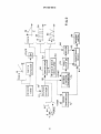
FIG. 1 is a diagram of the powered window lift control system of the present invention installed in a vehicle door;
FIG. 2 is a block diagram of the system of FIG. 1 employing a force sensing variable resistive switch;
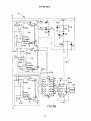
FIG. 3a is the lefthand portion of an electrical schematic of the system of FIG. 2 divided along parting line A-A;
FIG. 3b is the righthand portion of the schematic of FIG. 3a divided along parting line A-A;
FIG. 4 is a schematic of the motor relay for the system of FIG. 2;
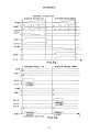
FIG. 5a is a timing diagram of the output of various circuit components of FIGS. 3a and 3b;
FIG. 5b is a timing diagram, similar to FIG. 5a, for the express function;
FIG. 6a is a view of the force sensitive variable impedance switch with actuator;
FIG. 6b is a view of the force sensitive variable impedance switch directly actuated by the user;
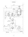
FIG. 7a is the left hand portion of an electrical schematic divided along parting line A-A of an alternate embodiment
of the invention of FIG. 2 employing a variable capacitance;
FIG. 7b is the right hand portion of the schematic of FIG. 4a divided along parting line A-A; and
FIG. 8 is a timing diagram for the outputs of the various devices of the circuit of FIGS. 7a and 7b.
2
EP 0 855 488 A2
DETAILED DESCRIPTION OF THE INVENTION
Referring to FIGS. 1, 6a and 6b, the system of the present invention is indicated generally at 10 and has a control
console 12 on a vehicle door 14 with a window 16 raised and lowered in tracks 18, 20 by a motorized mechanism indi5 cated generally at 22, connected to a window channel 24. At least one, and typically for a driver's door a plurality, of user
input controls or variable impedance devices 26, 28 are provided on console 12. Each of the devices indicated generally
at 26, 28 may have an actuator 30 which is directly acted upon or receives a force input from the vehicle operator or
driver's hand or fingers such as, for example, a pushbutton-type (not shown) actuator provided on the console 12. The
actuator 30 imparts a force on one of the pressure-responsive variable impedance devices 26, 28 situated on a base
10 or supporting structure 32, which forms a part of console 12. A rocker-type actuator 30 is shown in FIG. 6a which acts
upon a bar 34 which presses on devices 26, 28. Alternatively, the devices 26, 28 may be acted upon directly by the
user's finger as shown in FIG. 6b. It will be understood that other types of actuators may be employed, as for example,
by eliminating rocker 30 and applying user force directly to bar 34.
In one embodiment of the invention, devices 26, 28 comprise a force sensitive resistive device which provides
15 decreasing electrical resistance with increasing pressure from bar 34. In another embodiment of the invention as will be
described hereinafter in greater detail, a variable capacitor is employed to provide an increased capacitance with
increased force input.
The force-versus-impedance signal characteristics of the devices 26, 28 are indicated graphically at 36 in FIG. 2.
Referring to FIG. 2, The devices 26, 28 are connected along line 38 to a voltage divider network 40. The voltage
20 divider network 40 is operative to sense the variable impedance of the devices 26, 28 and to convert it to a voltage signal increasing with force, as indicated graphically at 44 and provided at the output line 46. A low-level force signal is
indicated at 44' and a high force level signal is indicated at 44" in the graphical representation of the voltage 44.
The output of the voltage divider 40 is connected along line 46 to the input of the comparator 48, which receives at
another input along line 42 the output of a triangle wave oscillator 50 having an output as shown graphically at 52 in
25 FIG. 2. The output of the comparator 48 along line 54 is indicated graphically as a series of pulses shown in solid outline
at 56 for the voltage signal 44' for a low force input, and in dashed line at 58 for the voltage signal 44" for a high force
input as compared with the output signal 52 of the triangle wave oscillator. The output of this variable impedance
devices 26, 28 is thus converted to a pulse-modulated (PWM) signal.
The output of the comparator 48 along line 54 is connected to the input of a power driver device or driver 60, such
30 as a Mosfet device, which provides a modulated driver signal along its output line 62 to a bi-directional motor relay 64
which operates the window lift motor 66.
Referring to FIGS. 3a and 3b, in the embodiment 10 of the invention, the variable impedance devices 26, 28 comprise separate variable-resistance, force-sensitive resistors PID1 and PID2 comprising resistors R1 and R2, respectively, connected in parallel and having the resistance values R1 , R2 in the present practice of the invention of about 335 4 kilo ohms in the fully actuated state, i.e., with maximum force applied thereto. Devices PID1 and PID2 are preferably
formed of force transducer ink with polymer film conductors.
Referring to FIG. 6a, the devices 26, 28 have a force impressed thereon by switch actuator 34 and rocker 12 upon
the driver pushing on the rocker actuator 30 associated with the individual device. Alternatively, the driver may apply
finger pressure directly to the devices 26, 28, as shown in FIG. 6b.
Such force sensitive resistance devices are known and commercially available, such as that supplied by Interlink
40
Electronics, Inc., Camorillo, California and shown and described in U.S. Patent 5,302,936.
Referring to FIGS. 3a and 3b, the signal processing of the circuitry is set forth below with respect to various modes
of operation of the powered window lift system of the embodiment 10. As applied pressure increases on PID1 or PID2,
the voltage at junction 68 increases. U2 amplifies this signal and produces an increasing voltage at U8B-5. This signal,
45 combined with the output from the 1 kHz triangle wave oscillator inputted at U8B-6, yields a pulse-width modulated signal at U8b-7. This voltage controls the duty cycle of the signal produced at U8B-7. Then, this PWM signal controls the
gate of the U9 Mosfet, producing this same signal at U10-5. This PWM signal is seen on the relay at U10-5. Also, this
PWM signal is seen by the motor, and the speed will increase proportionately in response to the applied PID pressure,
and the window speed controlled by the motor speed will follow exactly.
When PID1 is pressed, the voltage at junction 70 decreases proportionately with the applied force. When this voltso
age falls below V1 REF; which in the present practice of the invention is chosen as 9 volts, the relay comparator 72 is activated: U7A-1 goes high and U1-13 goes low, thus energizing U10 relay coil 78 through pin 7 thereof. The motor speed
responds to the PWM signal and the window moves up at a speed determined by the amount of force applied at the
PID. The motor speed increases with increasing duty cycle.
When the voltage at junction 70 falls below V2REF , which in the present practice of the invention is chosen as 5
55
volts, the "express" function comparator 74 is activated: the output of U3A-1 goes low, then the timed latch "on" function
76 is energized: U5 timing sequence starts, producing a 12-volt pulse of a 3-second duration at U5-3. This inverts at
U1-14 and energizes the U10 relay coil 78 at pin 7. In addition, that signal from U3A pulls the diode D5 low and starts
3
EP 0 855 488 A2
5
10
15
20
another timing sequence out of U4-3 of a 3-second duration. This signal then gates the U9 Mosfet "on" for that 3-second
duration. When the Mosfet is "on," the signal at U10-5 is grounded. Therefore, a full +12 volts is applied across the motor
leads, yielding maximum window speed in the "up" direction; thus, the "express up" mode is activated.
Referring to FIG. 4, when U9 grounds pin 5 of relay U10, one side of the motor is at ground potential at one of pins
1 and 8 of U10, and if either "up" coil 78 or "down" coil 80 is energized by U1 , full voltage is then applied from pin 4 of
U10 to the opposite side of the motor through the other of pins 1 and 8.
When PID2 is pressed, the voltage at junction 80 decreases proportionately with the applied force. When this voltage falls below V1 REF {i.e. , 9 volts), the relay comparator 72 (i.e., U7B-7) goes high and U1 -1 1 goes low, thus energizing U10 relay coil 80 through pin 2 thereof. The motor polarity is thus reversed, the motor speed responds to the PWM
signal from U9 and pin 5, and the window moves down at a speed determined by the amount of force applied at the PID.
The motor speed increases with increasing duty cycle.
When the voltage at junction 80 falls below V2REF, which in the present practice of the invention is chosen as +5
volts, then comparator 74 by U3B sends out a pulse triggering the U6 timing sequence of 3-second duration. This signal
inverts at U1-10 and energizes the U10 relay coil 80 for that 3-second duration. In addition, that signal from U3B-7 pulls
the diode D6 low and starts another timing sequence out of U4-3 of a 3-second duration. This signal then gates the U9
Mosfet "on" for that 3-second duration. When the Mosfet is "on," the signal at U10-5 is grounded, grounding one side of
the motor through pin 8. Therefore, a full +12 volts is applied across the motor leads through pin 1 of U10, yielding maximum window speed in the "down" direction, thus the "express down" mode is activated.
The timing of the output of the various devices of the circuit of FIGS. 3a and 3b is shown graphically in FIGS. 5a
and 5b for the different modes of operation described above. The values of resistances, capacitances and the integrated circuit device designations for the circuit of FIGS. 3a and 3b are given in Table I below.
TABLE I
(FIGS. 3a and 3b)
R: Ohms
C: \iids
U Type
D Type
1 - PID1
1-0.1
1 - ULN2003
1 - 16v, Z
2- PID2
2-0.1
2-LT1013
2 - 24v, Z
3- 4.4K
3 -.01
3A-1/2LT1013
3-115v, Z
4- 6.0K
4-0.4
3B-1/2LT1013
4 - 24v, Z
5- 10K
5-0.4
4-1CM7555
5-IN4148
6- 5.1K
6-0.1
5-1CM7555
6-IN4148
7- 10K
7 -.01
6-1CM7555
7-IN4148
8- 10K
8-0.4
7A-1/2LT1013
8-IN4145
9- 10K
9-0.1
7B-1/2LT1013
9-IN4148
10- 10K
10 -.01
8A-1/2LT1013
11- 14K
11-1
8B-1/2LT1013
12- 5.1
9-RFP50N05
13- 10K
10 -EP2 Relay
14- 10 Meg
15- 10 Meg
16- 5.1K
17- 10K
18- 36K
19- 10 Meg
20- 5.1 K
21 - 10K
4
EP 0 855 488 A2
TABLE I (continued)
(FIGS. 3a and 3b)
R: Ohms
C: \iids
U Type
D Type
22 - 10K
23 - 7K
24 - 320K
25 - 320K
26- 10K
27- 9K
28- 3K
Referring to FIGS. 7a and 7b, an alternate embodiment of the invention indicated generally at 100 is illustrated
wherein the variable impedance devices 26, 28 comprise a force-responsive, variable capacitance. Variable capacitance switches are known in the art, as for example, the device described in U.S. Patent 5,559,665 may be employed,
or any other suitable variable capacitance switch may be used. The variable capacitance device is of relatively thin, flat
configuration and, when installed, would have an appearance similar to that shown in FIGS. 6a and 6b.
The embodiment 100 is formed by substitution, for the voltage divider 40 in the system of FIG. 2, the circuit shown
in FIGS. 7a and 7b when the variable impedance devices 26, 28 comprise a force-sensitive, variable-capacitance
switch.
Referring to FIGS. 7a and 7b, the circuit receives power at connector terminals J1 and provides, through capacitor
network comprising capacitors C5 through C1 1, and the power supply voltage Vcc at 5 volts DC. The variable-capacitance-type devices 26, 28 of the embodiment 100 are connected from line 38 at terminals J2. The output signal 44 from
the voltage divider 40, comprising a voltage proportional to force applied to the capacitive switch devices 26, 28, is connected through terminal J3 along line 46 to the input of comparator 48.
The impedance of the force-sensitive capacitor devices 26, 28 is measured in a voltage divider circuit. The voltage
divider is comprised of a reference capacitor C3 and the switch 26, 28 capacitor to be measured connected in series.
The capacitors are simultaneously charged; and, the voltage at the point where the capacitors are connected together,
junction 102, indicates the impedance of the capacitor of the devices 26, 28. The logic uses a four step process to
measure the capacitive impedance.
Device U1' comprises a square wave oscillator which provides an output at pin 3 thereof to the input of a counter
device U2' which counts for valid states and then repeats. The outputs QA and QB of U2' are inputted to a one of eight
decoder U3' such that when the most significant bit goes high, QA and QB drive the least significant bit and it rotates
through states 4, 5, 6 and 7 by forcing them low.
The four steps of the process are generated by the following digital logic. Oscillator U1' provides a clock pulse to
the counter U2'. The first two outputs of the counter, which counts in binary from zero to three, are connected to the first
two inputs of U3', a 3:8 decoder which generates four separate sequential pulses. The first and third pulse are inverted
by U4' and labeled STB-A and STB-C on the schematic. The second and fourth pulses set and reset respectively a flipflop formed by the two remaining gates of U4'. This generates the charging control pulse labeled STB-B on the schematic.
In the first step of the impedance measuring process, control pulse STB-A activates analog switches in U5' which
connected
to both ends of the capacitor divider. This causes both capacitors to be completely discharged. In the
are
second step, the signal STB-A is "off" and STB-B is "on." The analog switches discharging the divider are now "off" and
the STB-B signal activates the analog switch in U5', which connects five volts to the capacitor divider, thus charging the
capacitors. In the third step, STB-B remains on (due to the flip flop) and STB-C is "on."
A buffer amplifier, U6, is connected to the junction of the capacitive divider and its output is connected to one of the
analog switches of U5. This switch is activated by STB-C which samples the voltage and stores the value on C4. The
output is buffered by another amplifier. In the fourth step, STB-C is turned "off" and the flip-flop in U4 is reset, which
deactivates STB-B. The whole process is then repeated.
The combination of the analog switch activated by STB-C, C4 and the buffer amplifier is called a sample and hold
circuit. The output is a dc voltage which is proportional to the impedance of the capacitance of the devices 26, 28 to be
measured.
The clock gates the output states, and the output of U3' is low only when U1' is low. As the outputs of U2' are changing, clock pulses from U1 ' hold U3' in the low or "off" state. When STB-A is high, this enables pins 5 and 6 of U5', which
EP 0 855 488 A2
5
10
goes high and shorts C3 and the capacitance of devices 26, 28 to ground and discharges them.
When STB-B is high this causes U5 to supply the 5 volts Vcc from pin 2 of U5' to C3 which is in series with the
capacitance of devices 26, 28, thus forming a voltage divider which has the voltage therefrom applied to U6', which is
a high-input impedance buffer providing a low impedance output to the comparator through terminals J3 and along line
26. U6', U5' and C4 form a sample and hold circuit; and, U6' drives J3 as a low impedance load without discharging C4.
When STB-C is high, five volts is applied in pin 12 of U5' and U5' outputs to C4. STB-C is high when STB-B is high
because U4' forms a set/reset latch. The next clock pulse toggles U2' to reset to 0,0. C4 is a storage element and stores
the voltage generated by the force on the capacitive devices 26, 28 and thus provides an output proportional to the
force. Referring to Table II, the states of the devices are shown for the four states 0,0, 0,1 , 1,0 and 1,1 of U2'.
The timing of the outputs of the various devices of the circuit of FIGS. 7a and 7b is illustrated in graphical form in
FIG. 8.
TABLE II
(FIGS. 7a & 7b)
25
UT
U2'
U3'
U5'
STB-A
STB-B
STB-C
Lo
0,0
Y4Lo
5,6 Hi
Hi
Lo
Lo
Lo
0,1
Y5Lo
13 Hi
Lo
Hi
Lo
Lo
1,0
Y6Lo
12 Hi
Lo
Hi
Hi
Lo
1,1
Y7Lo
Lo
Lo
Lo
The values of capacitance resistance and the device type designations are given in Table III for the circuit of FIGS.
7a and 7b.
TABLE III
(FIGS. 7a & 7b)
R:Ohms
C:\iids
1 - 10K, 5% 1/4W
1 - .001 , 50v
1' - LM 555
2 - 10K, 5% 1/4W
2 - .01 , 50v
2' - 74HC163
3- 150pf, 50v
3'-74HC138
4- .01,50v
4' -74HC00
5- 10, 35v
5' -74HC4066
6- .1,50v
6' -TLC272
U:Type
7- .1, 50v
8- .1, 50v
9- .1, 50v
10 - .1, 50v
11 - .1, 50v
so
55
The present invention thus provides a simple and effective relatively low cost technique for enabling the vehicle
operator to control the rate or speed of raising or lowering of a vehicle-powered window lift by the amount of pressure
or force the operator applies to the switch or rocker button, typically located on a console on the vehicle door. The user
input device utilizes a pressure-responsive, variable-impedance switch or input device, which in one embodiment comprises a pressure-sensitive, variable-resistance device and, in another embodiment, comprises a pressure-responsive,
variable capacitance.
Although the present invention has been described hereinabove with respect to the illustrated embodiments, it will
be understood that the invention is capable of modification and variation and is limited only by the scope of the following
claims.
6
EP 0 855 488 A2
Claims
1. A variable-speed vehicle window power lift system comprising:
(a) a force transducer responsive to increasing user finger pressure on an input member to provide a decreasing electrical impedance;
(b) a signal generating circuit connected to an onboard vehicle power source and operative to produce a control signal indicative of said change in impedance;
(c) a power amplifier circuit connected to an onboard vehicle power source and having its input connected to
receive said control signal and operative to provide a power driver signal modulated according to said control
signal;
(d) a movable vehicle window including structure operative for guiding window movement; and
(e) a bi-directional motor and a lift linkage connected to said window and driven by said motor, said motor operative upon said energization to lower and raise said vehicle window, wherein said motor is increased in speed
as said user's finger pressure on said input member increases.
2.
The system defined in claim 1, wherein said control signal is pulse width modulated.
3.
The system defined in claim 1, wherein said window motor includes a bi-directional relay.
4.
The system defined in claim 1, wherein said amplifier includes a Mosfet device.
5.
The system defined in claim 1, wherein said force transducer includes a polymer film with carbon interspersed
therein and said decreasing impedance comprises decreasing resistance.
6.
The system defined in claim 1, wherein said decreasing impedance comprises generating increasing capacitance.
7.
The system defined in claim 1, wherein said force transducer provides a decreasing resistance.
8.
A method of varying the speed of raising and lowering a vehicle-powered window lift comprising:
(a) guiding a vehicle window for movement in a generally vertical direction;
(b) engaging said window with lifting structure;
(c) connecting said lifting structure to an electrically energized motor;
(d) providing a force transducer and decreasing the impedance thereof in impedance responsive to increasing
user-applied force thereto;
(e) detecting changes in the impedance of said transducer;
(f) generating an electrical control signal indicative of said changes in impedance; and
(g) modulating a driver signal with said control signal and applying said driver signal to said motor and energizing said motor.
9.
The method defined in claim 9 wherein said step of energizing said motor includes latching said motor "on" at maximum speed when said impedance is decreased below a predetermined threshold.
10. A variable speed vehicle window power lift system comprising:
(a) a force transducer responsive to increasing user manual pressure on an input member to provide a
decreasing electrical impedance;
(b) circuit means connected to an onboard vehicle power source and operative to produce a control signal
indicative of said decreasing impedance;
(c) a power switching circuit connected to an onboard vehicle power source and having its input connected to
receive said control signal and operative to provide a power signal modulated according to said control signal;
(d) a moveable vehicle window including structure operable for guiding window movement;
(e) a bi-directional motor and lift linkage connected to said window and driven by said motor, said motor operative upon energization by said power signal to lower and raise said vehicle window, wherein said motor is
increased in speed as said user's manual pressure on said input member increases; and,
(f) timing means operative to latch said motor "on" at maximum speed when said impedance is decreased
below a predetermined threshold.
EP 0 855 488 A2
11. The system defined in claim 10 wherein said timing means is operative to latch said motor "on" for a predetermined
time period.
5
10
15
20
25
30
35
40
45
50
55
8
EP 0 855 488 A2
9
4
4^
<
J
£ or
w
i<
3
P
iJ i—
EP 0 855 488 A2
—50
FIG.
3 a
11
EP 0 855 488 A2
10
12V
D6
R8
60
r
I2V>RI4
84
r
76
TRIG
THRES
RESET
CV
GND
C4
4-I2V
Y I
|8
\//v»
VCC OUT 3
.
1
DISC
U5
62
TRIG
THRES
rtCV —
RESET
GND
CIO
12V
+I2V^RI5
f +I2V
8
VCC
DISC
OUT
U6
TRIG
C5
<7
THRES
RESET
CV
GND
64
-I-I2V
^OUTl
15
00UT.2
UT2
N2
■010
14
i 6
N3 tj, 0 U T 3
66
E h
C0IL2t
0UT4
N4
C0IL2- m
OUTSP?
^ N 5
MOTOR
_6_
COIL I- M
0UT6
N6
8
101
1_ N7^
COIL 1+
0UT7
GND
Nl
7
C7'
+-I2V
+ 2V
FIG.
12
3 B
<)
<>
NJ
CD
I
EP 0 855 488 A2
NORMAL
WINDOW
MOVES
FUNCTION
I WINDOW MOVES DOWN
UP I
JN 6 8
n
a
U687
/—
v
v
r\
r \
i
n
r\
/
JN 8 4
JN 7 0
v
—
v:
A
U7A-I
U I-13
JN 8 0
K.
U7B7
Ul-ll
F I G . 5 a
WINDOW MOVES
JN70
V
i
\
J
1 APPROX.\
3.0 S E C .
UI-14
JN80
V
U3B-7
V
/ APPRO X.V
3.0 SEC.
U I - 10
JN 8 4
\
/
U6-3
U4-2
MOVES DOWN
WINDOW
V
U3A-I
U5-3
UP
V
V
/ APPROX.
EXPRESS
\
FUNCTION
/APPR0X.\
FIG.
14
5 b
^
EP 0 855 488 A2
20
VCC
+ 5 VDC
100
I
Vcc
t 5 VDC
ENP
A
B
urRl
RST
DISC
THRES
>R2
TRIG
Vcc
8
CNTRL
C2
-J
GND
r
J2-I
>
J 2 - 2 >
F I G . 7 a
15
QA
U2'
8
4
OB
C
QC
D
QD
f> CK
[LOAD
OUT
ENT.
ROD
CLA
14
J3_
]2_
II
15
EP 0 855 488 A2
I
i
Vcc
f5VDC
Vcc
YO
,'5
A
YT , ' 4
8
oVcC
Jl4
Gl
Y2" , ' 3
>12
H
II
Y4
10
Y5
G2A
Y6
G2B
Y7j
rv6
U4 >
c
US"
STB-A
U4 y
I T
STB-C
J
10
12
U4>
STB-B
8
U4
Vcc
-5 VDC
13
l-l
>
C5 tn
X
J I - 2 >
C8
T
14
10
77
V
CIO:
U6'
e/7
EN
12
C
Vcc
5 VDC
Vcc
U5'
X
C7:
C6
1TC4
<
J3-I
~(
J3-2
F l G . 7 b
16
>—
^
46
^
y
_
r
_ ro
LJ
1
S
S
%
i
r
i
_ o
10
r
~ OJ
- I I I
\
>
j
-
': - l ) l }
-
_
_
}
r
-
l - ^
i
'
r
L
i
r
S
L
U
]
1
k
r
LI I
l l
r
o
o uj
~
- ® "10
=1
^
•■
ui
O uj
- m
in 5
~~
—
(-
i
I
r
S
r
r
o
o
~ OJ
k
r
oO
<
k
-
S
r
^■ r
k
k
}^
^
i
s
-
I - o
to
I -
k
- o
v
_
S• S
S
J
£
iS
3
_
—
!f2
_- in
r
r-^i
i «-<> -^-iO
*-»o
*-«o <->o
-^-io *-> 6 r- ()> *-«0
<-«<) *-»0
sS
I3 o g sS
§ S
iS
"<m i5
3 , ^^ 33
2
OJ
c k ?
U - 2
J
r
" I
"
1
£
iS
3
?
is
iS
3
£
^iS
=>
17
?< ? V
«»™ i«p p
(fl
(fl W
(fl tfl
w
tn
CO
o
—
U.