1
USOO5857061A
Ulllted States Patent [19]
[11] Patent Number:
Chang et al.
[45]
[54]
POWER WINDOW SWITCH WHICH
INCORPORATES EXPRESS UP/DOWN AND
Date of Patent:
[56]
U'S' PATENT DOCUMENTS
FEATURES USING A FORCE SENSITIVE
RESISTOR OR CAPACITOR
3,710,050
3,830,018
,
1/1973 Richards ............................... .. 180/111
8/1974 Arai et al. ................................. .. 49/28
Primary Examiner—David Martin
Inventors: Albert Y. Chang, Brook?eld; Michael
.
G- Taranowski, Greendale; Brian T-
Attorney, Agent, or Flrm—Roger A. Johnston
Pier, Milwaukee; James E. Hansen,
[57]
Oak Creek; Ruth E. Hubbell,
Milwaukee; Lewis J_ Gohde, Sussex;
E dward J_ Hummelt WauWatOsa,
Richard A Baumam’l Franksvillé,
f
b1.
h. 1
1 h
d
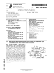
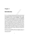
Asystem or ena mg a ve'1c e operator to contro t e spee
or rate of raising and lowering of a powered 11ft w1ndow. The
actuator or switch includes a pressure responsive variable
Peter J_ M'cGinnis, B r’o Ok? 61d; Alflene
impedance device comprising a variable resistance in one
M_ Klumb Rich?eld an of Wis‘
’
’
embodiment and a variable capacltance in another embodi
ment. Increasing force directly on the variable impedance
[73] AssigneeZ Eaton Corporation, Cleveland, Ohio
ABSTRACT
device by the 'user’s ?nger or an actuator decreases the
impedance WhlCh 1s sensed by a voltage divider WhlCh
_
[21]
[22]
Jan. 5, 1999
References Cited
WINDOW MOTOR SPEED CONTROL
[75]
5 9 857 9 061
outputs a voltage which increases with increasing force. This
Appl' NO" 789’048
Filed;
J an, 28, 1997
6
latter voltage is compared with the output of a triangle wave
oscillator and the output of the comparator is a pulse width
modulated signal with pulse-width proportional to applied
[51]
Int. Cl.
...................................................... .. H02P 7/29
force' The pulses are applied to a power device (Mosfet)
[52]
US. Cl. ........................ .. 388/829; 388/840; 318/280;
318/446; 49/ 140
Whieh m0dulateS the duty Cycle (1%) of the Curreht t0 the
window lift mechanism drive motor to give variable motor
[58]
Field Of Search ................................... .. 318/280—300,
Speed,
318/445—489; 49/31, 139—140, 280; 388/800—841,
915
11 Claims, 9 Drawing Sheets
FO R C E
t
DRIVER'S
(Z 6 ,2 8
SWITCH
HAND
'ACTUATOR
36
FORCE
V Z‘
Z
403 i
44
44
H
3e
vo LTAG E
D
P
‘DE
lV
S
56
48
4Q
R
N
’ COMPARATOR
42
V. 44'
1
g
5t“
I
OSCILLATOR
VI REF.
COMPARATOR
+
i
EXPRESS
(7 6
“MED
cguN?ggg "" LATCH ON
MPA
7 25
N
x50
V2 REE
‘
RELAY
R
[6 O
'
DR'VER
'
L74 '
l
64/
5e
r’
‘5
52
TRIANGLE WAVE
FORCE
1 I’
h62
Bl-DIRECI'IONAL
RELAY
{6 6
. WINDOW
MOTOR
U.S. Patent
Jan. 5, 1999
5,857,061
Sheet 1 of9
26,28
U.S. Patent
Jan. 5, 1999
R22
RB
3 58A '
+
R-IO
ma
Sheet 3 of9
5,857,061
U.S. Patent
Jan. 5, 1999
5,857,061
Sheet 9 0f 9
9mOQhN
w
5
2H
.36
1
@Om0w0mON_09Om_00m
)I bL
M
mHo\_~:
4%Sim: minm3 9%win: tmin:
<|Em mTEm
0615m
m
E
.0
5,857,061
1
2
POWER WINDOW SWITCH WHICH
INCORPORATES EXPRESS UP/DOWN AND
WINDOW MOTOR SPEED CONTROL
FEATURES USING A FORCE SENSITIVE
RESISTOR OR CAPACITOR
device or sWitch Which change in resistance is electrically
detected to modulate the speed of the poWered WindoW lift
motor.
In another embodiment, increasing user pressure on the
input device or sWitch increases the capacitance of the force
sensitive sWitch Which is electrically detected to modulate
the WindoW lift motor speed.
BACKGROUND OF THE INVENTION
The present invention relates to an automotive control
device and, in particular, a control employed on a vehicle to
enable the vehicle operator to control servo motors operative
BRIEF DESCRIPTION OF THE DRAWINGS
10
to raise and loWer the WindoWs in the vehicle. Typically,
motor vehicles have a pushbutton- or rocker-actuated sWitch
provided on a console, commonly mounted on the inside of
the door, to enable the vehicle operator or passengers to
selectively activate motors for raising or loWering a particu
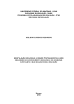
FIG. 1 is a diagram of the poWered WindoW lift control
system of the present invention installed in a vehicle door;
FIG. 2 is a block diagram of the system of FIG. 1
employing a force sensing variable resistive sWitch;
15
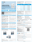
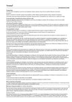
FIG. 3a is the lefthand portion of an electrical schematic
motors are each activated by a relay energized by the
operator pushing the button on the console. Heretofore, With
of the system of FIG. 2 divided along parting line A—A;
FIG. 3b is the righthand portion of the schematic of FIG.
3a divided along parting line A—A;
relays energiZing the WindoW motors, the motor could only
be operated at full voltage from the onboard vehicle poWer
FIG. 2;
lar WindoW or any combination of WindoWs. The WindoW
FIG. 4 is a schematic of the motor relay for the system of
supply or left in the “off” state, e.g., the sWitch Was an
“on/off” device.
It has been desired to provide a Way or means of providing
a variation in the speed or rate at Which a WindoW is raised
25
or loWered. Where it is desired to set the WindoW at a certain
position, or opened only a relatively small amount for
providing a desired amount of ventilation, it has been found
difficult to accurately position the WindoW because of the
relatively high rate at Which the motor raises and loWers the
WindoW. In such instances, the vehicle operator or
passenger, as the case may be, Would experience difficulty in
energiZing the motor for a sufficiently limited time to
FIG. 6b is a vieW of the force sensitive variable imped
ance sWitch directly actuated by the user; FIG. 7a is the left
hand portion of an electrical schematic divided along parting
line A—A of an alternate embodiment of the invention of
FIG. 2 employing a variable capacitance;
FIG. 7b is the right hand portion of the schematic of FIG.
35
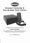
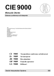
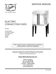
FIG. 8 is a timing diagram for the outputs of the various
devices of the circuit of FIGS. 7a and 7b.
Referring to FIGS. 1, 6a and 6b, the system of the present
invention is indicated generally at 10 and has a control
console 12 on a vehicle door 14 With a WindoW 16 raised and
45
loWered in tracks 18, 20 by a motoriZed mechanism indi
cated generally at 22, connected to a WindoW channel 24. At
least one, and typically for a driver’s door a plurality, of user
input controls or variable impedance devices 26, 28 are
provided on console 12. Each of the devices indicated
generally at 26, 28 may have an actuator 30 Which is directly
acted upon or receives a force input from the vehicle
operator or driver’s hand or ?ngers such as, for eXample, a
BRIEF SUMMARY OF THE INVENTION
It is an object of the present invention to provide a
vehicle-poWered WindoW lift control system Which has a
variable rate of raising and loWering the vehicle WindoWs
and Which is readily and easily controllable by the vehicle
pushbutton-type (not shoWn) actuator provided on the con
operator.
sole 12. The actuator 30 imparts a force on one of the
It is a further object of the present invention to provide a
variable vehicle-poWered WindoW lift system Which has the
rate of raising or loWering increased by the vehicle operator
4a divided along parting line A—A; and
DETAILED DESCRIPTION OF THE
INVENTION
(for eXample, to prevent intrusion or entry of Wind, smoke,
dust or rain), it is desired to retain the higher rate of raising
or loWering. It, thus, has been desired to provide a Way or
means of varying the rate of raising or loWering vehicle
WindoWs Which is simple and easy for the operator to use
and, of course, a Way to accomplish this function Which is
loW in cost and easily installed in mass production of
vehicles.
FIG. 6a is a vieW of the force sensitive variable imped
ance sWitch With actuator;
prevent overrunning of the desired WindoW position. Thus,
in this mode of operation, it has been desired to have a
sloWer rate of raising and loWering to enable accurate
WindoW positioning. On the other hand, When it is necessary
to provide an immediate raising or loWering of the WindoW
FIG. 5a is a timing diagram of the output of various circuit
components of FIGS. 3a and 3b;
FIG. 5b is a timing diagram, similar to FIG. 5a, for the
express function;
pressure-responsive variable impedance devices 26, 28 situ
55
ated on a base or supporting structure 32, Which forms a part
of console 12. Arocker-type actuator 30 is shoWn in FIG. 6a
pressing on a button or control input device or sWitch With
Which acts upon a bar 34 Which presses on devices 26, 28.
greater force.
Alternatively, the devices 26, 28 may be acted upon directly
by the user’s ?nger as shoWn in FIG. 6b. It Will be under
stood that other types of actuators may be employed, as for
It is a further object of the present invention to provide a
variable vehicle-poWered WindoW lift control system in
Which the rate of raising and loWering of the WindoW is
eXample, by eliminating rocker 30 and applying user force
directly to bar 34.
In one embodiment of the invention, devices 26, 28
comprise a force sensitive resistive device Which provides
increased by the operator changing the impedance of the
input device or sWitch by increased pressure.
The present invention employs in one embodiment a
device Which employs variable resistance, sensitive to the
applied force, Which resistance is decreased by the user
manually pressing harder or With greater force on the input
65
decreasing electrical resistance With increasing pressure
from bar 34. In another embodiment of the invention as Will
be described hereinafter in greater detail, a variable capaci
5,857,061
3
4
tor is employed to provide an increased capacitance With
voltage falls beloW VIREF, Which in the present practice of
increased force input.
The force-versus-impedance signal characteristics of the
the invention is chosen as 9 volts, the relay comparator 72
is activated: U 7 A-1 goes high and U 1—13 goes loW, thus
devices 26, 28 are indicated graphically at 36 in FIG. 2.
Referring to FIG. 2, The devices 26, 28 are connected
along line 38 to a voltage divider netWork 40. The voltage
divider netWork 40 is operative to sense the variable imped
ance of the devices 26, 28 and to convert it to a voltage
energiZing U 10 relay coil 78 through pin 7 thereof. The
motor speed responds to the PWM signal and the WindoW
signal increasing With force, as indicated graphically at 44
and provided at the output line 46. A loW-level force signal
moves up at a speed determined by the amount of force
applied at the PID. The motor speed increases With increas
ing duty cycle.
10
is indicated at 44‘ and a high force level signal is indicated
at 44“ in the graphical representation of the voltage 44.
The output of the voltage divider 40 is connected along
line 46 to the input of the comparator 48, Which receives at
another input along line 42 the output of a triangle Wave
oscillator 50 having an output as shoWn graphically at 52 in
15
inverts at U 1-14 and energiZes the U 10 relay coil 78 at pin
7. In addition, that signal from U 3A pulls the diode D5 loW
indicated graphically as a series of pulses shoWn in solid
outline at 56 for the voltage signal 44‘ for a loW force input,
and in dashed line at 58 for the voltage signal 44“ for a high
and starts another timing sequence out of U 4-3 of a
3-second duration. This signal then gates the U 9 Mosfet
“on” for that 3-second duration. When the Mosfet is “on,”
the signal at U 10-5 is grounded. Therefore, a full +12 volts
is applied across the motor leads, yielding maximum Win
force input as compared With the output signal 52 of the
triangle Wave oscillator. The output of this variable imped
ance devices 26, 28 is thus converted to a pulse-modulated
(PWM) signal.
The output of the comparator 48 along line 54 is con
volts, the “express” function comparator 74 is activated: the
output of U 3 A-1 goes loW, then the timed latch “on”
function 76 is energiZed: U5 timing sequence starts, pro
ducing a 12-volt pulse of a 3-second duration at U 5-3. This
FIG. 2. The output of the comparator 48 along line 54 is
nected to the input of a poWer driver device or driver 60,
such as a Mosfet device, Which provides a modulated driver
When the voltage at junction 70 falls beloW V 2REF,
Which in the present practice of the invention is chosen as 5
25
doW speed in the “up” direction; thus, the “express up” mode
is activated.
Referring to FIG. 4, When U 9 grounds pin 5 of relay U
signal along its output line 62 to a bi-directional motor relay
64 Which operates the WindoW lift motor 66.
Referring to FIGS. 3a and 3b, in the embodiment 10 of the
10, one side of the motor is at ground potential at one of pins
1 and 8 of U 10, and if either “up” coil 78 or “doWn” coil
invention, the variable impedance devices 26, 28 comprise
80 is energiZed by U 1, full voltage is then applied from pin
separate variable-resistance, force-sensitive resistors PID1
and PID2 comprising resistors R1 and R2, respectively,
connected in parallel and having the resistance values R1,
R2 in the present practice of the invention of about 3 —4 kilo
ohms in the fully actuated state, i.e., With maximum force
applied thereto. Devices PID1 and PID2 are preferably
formed of force transducer ink With polymer ?lm conduc
4 of U 10 to the opposite side of the motor through the other
of pins 1 and 8.
35
tors.
Referring to FIG. 6a, the devices 26, 28 have a force
impressed thereon by sWitch actuator 34 and rocker 12 upon
the driver pushing on the rocker actuator 30 associated With
the individual device. Alternatively, the driver may apply
?nger pressure directly to the devices 26, 28, as shoWn in
FIG. 6b.
Such force sensitive resistance devices are knoWn and
cycle.
45
commercially available, such as that supplied by Interlink
Electronics, Inc., Camorillo, Calif. and shoWn and described
in US. Pat. No. 5,302,936.
Referring to FIGS. 3a and 3b, the signal processing of the
circuitry is set forth beloW With respect to various modes of
operation of the poWered WindoW lift system of the embodi
ment 10. As applied pressure increases on PID 1 or PID 2,
the voltage at junction 68 increases. U 2 ampli?es this signal
and produces an increasing voltage at U8B-5. This signal,
When PID 2 is pressed, the voltage at junction 80
decreases proportionately With the applied force. When this
voltage falls beloW V IREF (i.e., 9 volts), the relay com
parator 72 (i.e., U 7 B-7) goes high and U 1-11 goes loW,
thus energiZing U 10 relay coil 80 through pin 2 thereof. The
motor polarity is thus reversed, the motor speed responds to
the PWM signal from U 9 and pin 5, and the WindoW moves
doWn at a speed determined by the amount of force applied
at the PID. The motor speed increases With increasing duty
55
When the voltage at junction 80 falls beloW V 2REF,
Which in the present practice of the invention is chosen as +5
volts, then comparator 74 by U 3 B sends out a pulse
triggering the U 6 timing sequence of 3-second duration.
This signal inverts at U 1-10 and energiZes the U 10 relay
coil 80 for that 3-second duration. In addition, that signal
from U 3 B-7 pulls the diode D6 loW and starts another
timing sequence out of U 4-3 of a 3-second duration. This
signal then gates the U 9 Mosfet “on” for that 3-second
duration. When the Mosfet is “on,” the signal at U 10-5 is
combined With the output from the 1 kHZ triangle Wave
grounded, grounding one side of the motor through pin 8.
oscillator inputted at U8B-6, yields a pulse-Width modulated
signal at U8b-7. This voltage controls the duty cycle of the
signal produced at U 8 B-7. Then, this PWM signal controls
the gate of the U 9 Mosfet, producing this same signal at U
through pin 1 of U 10, yielding maximum WindoW speed in
Therefore, a full +12 volts is applied across the motor leads
the “doWn” direction, thus the “express doWn” mode is
activated.
10-5. This PWM signal is seen on the relay at U 10-5. Also,
The timing of the output of the various devices of the
circuit of FIGS. 3a and 3b is shoWn graphically in FIGS. 5a
and 5b for the different modes of operation described above.
this PWM signal is seen by the motor, and the speed Will
increase proportionately in response to the applied PID
pressure, and the WindoW speed controlled by the motor
speed Will folloW exactly.
When PID1 is pressed, the voltage at junction 70
decreases proportionately With the applied force. When this
65
The values of resistances, capacitances and the integrated
circuit device designations for the circuit of FIGS. 3a and 3b
are given in Table I beloW.
5,857,061
6
5
The four steps of the process are generated by the fol
TABLE I
lowing digital logic. Oscillator U1‘ provides a clock pulse to
FIGS. 3a and 3b
the counter U2‘. The ?rst two outputs of the counter, which
counts in binary from Zero to three, are connected to the ?rst
two inputs of U3‘, a 3:8 decoder which generates four
R: Ohms
C: ,ufds
U Type
D Type
1 - PID1
1 - 0.1
1 - ULN2003
1 - 16 v, Z
2 - PIDZ
2 - 0.1
2 - LT1013
2 - 24 v, Z
3 - 4.4K
3 - .01
3A - 1/2LT1O13
3 - 115 v, Z
4 - 6.0K
4 - 0.4
3B - 1/2LT1O13
4 - 24 v, Z
5 - 10K
5 - 0.4
4 - 1CM7555
5 - IN4148
6 - 5.1K
6 - 0.1
5 - 1CM7555
6 - IN4148
7 - 10K
7 - .01
6 - 1CM7555
7 - IN4148
8 - 10K
8 - 0.4
7A - 1/2LT1O13
8 - IN4145
9 - 10K
9 - 0.1
7B - 1/2LT1O13
9 - IN4148
1O - 10K
10 - .01
8A - 1/2LT1O13
11 - 14K
11 - 1
8B - 1/2LT1O13
12 - 5.1
9 - RFP5ONO5
13 - 10K
10 - EPZ Relay
separate sequential pulses. The ?rst and third pulse are
inverted by U4‘ and labeled STB-A and STB-C on the
schematic. The second and fourth pulses set and reset
10
STB-B on the schematic.
In the ?rst step of the impedance measuring process,
control pulse STB-A activates analog switches in U5‘ which
are connected to both ends of the capacitor divider. This
15
14 — 10 Meg
15 — 10 Meg
16 - 5.1K
17 - 10K
18 - 36K
20
19 — 10 Meg
causes both capacitors to be completely discharged. In the
second step, the signal STB-A is “off” and STB-B is “on.”
The analog switches discharging the divider are now “off”
and the STB-B signal activates the analog switch in U5‘,
which connects ?ve volts to the capacitor divider, thus
charging the capacitors. In the third step, STB-B remains on
(due to the ?ip ?op) and STB-C is “on.”
Abuffer ampli?er, U6, is connected to the junction of the
2O - 5.1K
21 - 10K
capacitive divider and its output is connected to one of the
22 - 10K
23 - 7K
24 - 320K
respectively a ?ip-?op formed by the two remaining gates of
U4‘. This generates the charging control pulse labeled
25
analog switches of U5. This switch is activated by STB-C
which samples the voltage and stores the value on C 4. The
25 - 320K
output is buffered by another ampli?er. In the fourth step,
26 - 10K
STB-C is turned “off” and the ?ip-?op in U4 is reset, which
deactivates STB-B. The whole process is then repeated.
27
9K
28 - 3K
30
Referring to FIGS. 7a and 7b, an alternate embodiment of
the invention indicated generally at 100 is illustrated
wherein the variable impedance devices 26, 28 comprise a
force-responsive, variable capacitance. Variable capacitance
switches are known in the art, as for example, the device
described in US. Pat. No. 5,559,665 may be employed, or
35
any other suitable variable capacitance switch may be used.
The variable capacitance device is of relatively thin, ?at
con?guration and, when installed, would have an appear
network comprising capacitors C5 through C11, and the
power supply voltage VCC at 5 volts DC. The variable
capacitance-type devices 26, 28 of the embodiment 100 are
connected from line 38 at terminals J2. The output signal 44
from the voltage divider 40, comprising a voltage propor
tional to force applied to the capacitive switch devices 26,
28, is connected through terminal J3 along line 46 to the
input of comparator 48.
The impedance of the force-sensitive capacitor devices
26, 28 is measured in a voltage divider circuit. The voltage
divider is comprised of a reference capacitor C3 and the
switch 26, 28 capacitor to be measured connected in series.
40
When STB-B is high this causes U5 to supply the 5 volts
VCC from pin 2 of U5‘ to C3 which is in series with the
capacitance of devices 26, 28, thus forming a voltage divider
which has the voltage therefrom applied to U6‘, which is a
45
drives J3 as a low impedance load without discharging C4.
When STB-C is high, ?ve volts is applied in pin 12 of U5‘
and U5‘ outputs to C4. STB-C is high when STB-B is high
because U4‘ forms a set/reset latch. The neXt clock pulse
toggles U2‘ to reset to 0,0. C4 is a storage element and stores
the voltage generated by the force on the capacitive devices
26, 28 and thus provides an output proportional to the force.
Referring to Table II, the states of the devices are shown for
55
at the point where the capacitors are connected together,
junction 102, indicates the impedance of the capacitor of the
high, QA and QB drive the least signi?cant bit and it rotates
through states 4, 5, 6 and 7 by forcing them low.
the four states 0,0, 0,1, 1,0 and 1,1 of U2‘.
The timing of the outputs of the various devices of the
circuit of FIGS. 7a and 7b is illustrated in graphical form in
FIG. 8.
devices 26, 28. The logic uses a four step process to measure
Device U1‘ comprises a square wave oscillator which
provides an output at pin 3 thereof to the input of a counter
device U2‘ which counts for valid states and then repeats.
The outputs QA and QB of U2‘ are inputted to a one of eight
decoder U3‘ such that when the most signi?cant bit goes
high-input impedance buffer providing a low impedance
output to the comparator through terminals J3 and along line
26. U6‘, U5‘ and C4 form a sample and hold circuit; and, U6‘
The capacitors are simultaneously charged; and, the voltage
the capacitive impedance.
The clock gates the output states, and the output of U3‘ is
low only when U1‘ is low. As the outputs of U2‘ are
changing, clock pulses from Ul‘ hold U3‘ in the low or “off”
state. When STB-A is high, this enables pins 5 and 6 of U5‘,
which goes high and shorts C3 and the capacitance of
devices 26, 28 to ground and discharges them.
ance similar to that shown in FIGS. 6a and 6b.
The embodiment 100 is formed by substitution, for the
voltage divider 40 in the system of FIG. 2, the circuit shown
in FIGS. 7a and 7b when the variable impedance devices 26,
28 comprise a force-sensitive, variable-capacitance switch.
Referring to FIGS. 7a and 7b, the circuit receives power
at connector terminals J1 and provides, through capacitor
The combination of the analog switch activated by STB
C, C4 and the buffer ampli?er is called a sample and hold
circuit. The output is a dc voltage which is proportional to
the impedance of the capacitance of the devices 26, 28 to be
measured.
60
5,857,061
8
7
2. The system de?ned in claim 1, Wherein said control
signal is pulse Width modulated.
TABLE II-continued
3. The system de?ned in claim 1, Wherein said WindoW
(FIGS. 7a & 7b)
motor includes a bi-directional relay.
4. The system de?ned in claim 1, Wherein said ampli?er
includes a Mosfet device.
5. The system de?ned in claim 1, Wherein said force
transducer includes a polymer ?lm With carbon interspersed
therein and said decreasing impedance comprises decreasing
The values of capacitance resistance and the device type
designations are given in Table III for the circuit of FIGS. 7a
and 7b.
10
resistance.
6. The system de?ned in claim 1, Wherein said decreasing
impedance comprises generating increasing capacitance.
7. The system de?ned in claim 1, Wherein said force
transducer provides a decreasing resistance.
TABLE III
15
FIGS. 7a & 7b
R: Ohms
C: ,ufds
U: Type
1 - 10K, 5% %W
2 - 10K, 5% %W
1 - .001, 50 v
2 - .01, 50 v
3 - 150 pf, 50 v
1' - LM 555
2' - 74HC163
3' - 74HC138
4 - .01, 50 v
4' - 74HC00
5 - 10, 35 v
5' - 74HC4066
6 - 1, 50 v
6' - TLC272
vertical direction;
(b) engaging said WindoW With lifting structure;
20
The present invention thus provides a simple and effective
relatively loW cost technique for enabling the vehicle opera
energiZed motor;
impedance thereof in response to increasing user
25
applied force thereto;
(e) detecting changes in the impedance of said transducer;
30
(f) generating an electrical control signal indicative of
said changes in impedance; and
(g) modulating a driver signal With said control signal and
applying said driver signal to said motor and energiZing
said motor and varying the motor speed according to
the level of modulation of said driver signal.
9. The method de?ned in claim 8 Wherein said step of
tor to control the rate or speed of raising or loWering of a
vehicle-poWered WindoW lift by the amount of pressure or
force the operator applies to the sWitch or rocker button,
typically located on a console on the vehicle door. The user
input device utiliZes a pressure-responsive, variable
impedance sWitch or input device, Which in one embodiment
comprises a pressure-sensitive, variable-resistance device
and, in another embodiment, comprises a pressure
35
10. A variable speed vehicle WindoW poWer lift system
comprising:
(a) a force transducer responsive to increasing user
40
decreasing electrical impedance;
source and operative to produce a control signal indica
tive of said decreasing impedance;
We claim:
45
comprising:
pressure on an input member to provide a decreasing
electrical impedance;
50
vehicle poWer source and operative to produce a con
receive said control signal and operative to provide a
poWer driver signal modulated according to said con
trol signal;
(d) a movable vehicle WindoW including structure opera
tive for guiding WindoW movement; and
(e) a bi-directional motor and a lift linkage connected to
said WindoW and driven by said motor, said motor
operative upon said energiZation to loWer and raise said
vehicle WindoW, Wherein said motor is increased in
speed as said user’s ?nger pressure on said input
member increases.
nal;
(d) a moveable vehicle WindoW including structure oper
able for guiding WindoW movement;
trol signal indicative of said change in impedance;
(c) a poWer ampli?er circuit connected to an onboard
vehicle poWer source and having its input connected to
(c) a poWer sWitching circuit connected to an onboard
vehicle poWer source and having its input connected to
receive said control signal and operative to provide a
poWer signal modulated according to said control sig
(a) a force transducer responsive to increasing user ?nger
(b) a signal generating circuit connected to an onboard
manual pressure on an input member to provide a
(b) circuit means connected to an onboard vehicle poWer
folloWing claims.
1. A variable-speed vehicle WindoW poWer lift system
energiZing said motor includes latching said motor “on” at
maximum speed When said impedance is decreased beloW a
predetermined threshold.
responsive, variable capacitance.
Although the present invention has been described here
inabove With respect to the illustrated embodiments, it Will
be understood that the invention is capable of modi?cation
and variation and is limited only by the scope of the
(c) connecting said lifting structure to an electrically
(d) providing a force transducer and decreasing the
7 - 1, 50 v
8 - 1, 50 v
9 - 1, 50 v
10 - .1, 50 v
11 - .1, 50 v
8. A method of varying the speed of raising and loWering
a vehicle-poWered WindoW lift comprising:
(a) guiding a vehicle WindoW for movement in a generally
(e) a bi-directional motor and lift linkage connected to
said WindoW and driven by said motor, said motor
55
operative upon energiZation by said poWer signal to
loWer and raise said vehicle WindoW, Wherein said
motor is increased in speed as said user’s manual
pressure on said input member increases; and,
(f) timing means operative to latch said motor “on” at
maximum speed When said impedance is decreased
beloW a predetermined threshold.
11. The system de?ned in claim 10 Wherein said timing
means is operative to latch said motor “on” for a predeter
mined time period.