1
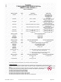
TYPE EXAMINATION CERTIFICATE
[1]
e
Equipment or Protective System intended for use
in Potentially Explosive Atmospheres
Directive 94/9/EC
[2]
[3]
Type Examination Certificate Number: DEMKO
[4]
Equipment: Programmable
[5]
Manufacturer: Rockwell
[6]
Address:
[7]
This equipment and any acceptable variation thereto are specified in the schedule to this certificate and the documents therein referred to.
[8]
UL International Demko A/S certifies that this equipment has been found to comply with the Essential Health and Safety Requirements that
relate to the design of Category 3 equipment, which is intended for use in potentially explosive atmospheres. These Essential Health and
Safety Requirements are given in Annex II to the European Union Directive 94/9/EC of 23 March 1994.
1201 S. 2
nd
13 ATEX 1325026X Rev. 7
Controllers – 1756 Series
Automation / Allen-Bradley
St. Milwaukee, WI 53204, USA
The examination and test results are recorded in confidential report no.
[9]
4786364019
Compliance with the Essential Health and Safety Requirements, with the exception of those listed in the schedule of this certificate, has been
assessed by reference to Standards:
EN 60079-0:2012+A11:2013
EN 60079-15:2010
[10]
If the sign "X" is placed after the certificate number, it indicates that the equipment or protective system is subject to special conditions for safe
use specified in the schedule to this certificate.
[11]
This Type examination certificate relates only to the design of the specified equipment, and not to specific items of equipment subsequently
manufactured.
[12]
The marking of the equipment or protective system shall include the following:
e II 3 G
e II 3 G
e II 3 G
Certification Manager
Jan-Erik Storgaard
Ex nA IIC T5 Gc
Ex nA IIC T4 Gc
Ex nA IIC T3 Gc
This is to certify that the sample(s) of the Equipment described herein (“Certified Equipment”) has been
investigated and found in compliance with the Standard(s) indicated on this Certificate, in accordance with the
ATEX Equipment Certification Program Requirements. This certificate and test results obtained apply only to
the equipment sample(s) submitted by the Manufacturer. UL did not select the sample(s) or determine whether
the sample(s) provided were representative of other manufactured equipment. UL has not established FollowUp Service or other surveillance of the equipment. The Manufacturer is solely and fully responsible for
conformity of all equipment to all applicable Standards, specifications, requirements or Directives. The test
results may not be used, in whole or in part, in any other document without UL’s prior written approval.
Date of issue: 2013-08-07
Re-issued: 2014-09-09
Certification Body
00-IC-F0060 – Issue 7.0
UL International Demko A/S, Borupvang 5A, 2750 Ballerup, Denmark
Tel. +45 44 85 65 65, [email protected], www.ul.com
This certificate may only be reproduced in its entirety and without any change, schedule included.
Page 1 of 9
Schedule
TYPE EXAMINATION CERTIFICATE No.
[13]
[14]
DEMKO 13 ATEX 1325026X Rev. 7
Report: 4786364019
[15]
Description of Equipment:
Modules 1756-RM2 and 1756-RM2XT are modular component of the Allen-Bradley ControlLogix industrial control system. The XT suffix is
designed for extended temperature operation of -25 C to 70 C. Modules are utilized as a high performance digital signal communications
interface between redundant ControlLogix system chassis over a fiber optic links. They are used in pairs to provide the hot backup function
in a ControlLogix system.
1756-EN series modules are EtherNet/IP communication modules for use with the Logix500 controller. They communicate with various
devices on the Ethernet network. Modules with XT suffix have an extended range of operating temperatures. Configurations vary in terms
of ports provided as well as the firmware that is used.
1756-IF8I, 1756-IRT8I, 1756-OF8I modules are analog input/output modules for use with the Logix500 controller. They provide various
voltage/current analog inputs and outputs to span many applications. Input information and output status can be shared among multiple
ControlLogix controllers.
1756-P series modules are chassis power supplies and adapters that provide power to a Rockwell PLC chassis. The series includes DC
and AC power supplies of both regular and extended temperature range, as well as a chassis adapter that allows for load sharing and
redundancy between two power supplies connected to it. When one power supply goes completely offline, the full load is put on the active
power supply. The power supplies are mounted separately from the chassis and attach to the 1756-PSCA2 (regular temperature range) or
1756-PSCA2XT (extended temperature range) chassis adapter through a cable. The chassis adapter itself is mounted to the side of a
Rockwell PLC chassis rack.
1756-CN series modules are modular components of the Allen-Bradley ControlLogix industrial control system. They are utilized as data
communication interfaces between the control system and other systems or devices operating on a ControlNet communications network.
The ControlNet network is a proprietary, industrial communications network that uses an impedance limited coaxial conductor media to
transmit digital data to and from connected devices. This equipment is powered from the ControlLogix system extra-low-voltage, limited
energy power supply, through the system backplane and chassis. This equipment can be connected to the ControlNet network by using a
tap (1786-TPR, 1786-TPS, 1786-TPYR, 1786-TPYS).
1756-DHRIO series is a modular component of the Allen-Bradley ControlLogix industrial control system. It is intended to function as a
communications interface between various programmable control systems or subsystems and the ControlLogix system. The digital
communications signals are isolated from the system backplane and operate at Limited Voltage/Current potentials. This module is powered
by the system backplane. It is equipped with three ports for connection of shielded twisted pair DataHighway or Remote I/O
communications media. One of these ports is an 8 pin mini DIN connector intended for temporary connection to programming or diagnostic
equipment, the other two are 3 position removable terminal block connectors for permanently installed DH or RIO media cable.
1756-A series B & C chassis modules are a modular component of the Allen-Bradley ControlLogix™ industrial control system. It provides
physical mounting, bonding to the system protective earth equipment grounding conductor, bonding to the system functional ground
conductor, limited energy power supply distribution conductors, and digital data transfer and system interconnection conductors for all of the
plug-in modules of the system. It is equipped to accept a plug-in system power supply on the left most side, and all of the various types of
control system modules in the remaining slots. The numerical portion of the model number indicates the number of slots.
1756-L73XT CONTROLLER WITH 8MB MEMORY is be designed to provide a solution for those customers that are looking for higher raw
performance for motion applications, while preserving the programming software, network communication and user interface of the Logix
family. The 1756-L7x will use the 1756-L6x as a baseline to enhance this product in the following ways: Provide the use of Secure Digital
(SD) cards, a Universal Serial Bus (USB) port on the front face and utilizing the high clock speeds of the new ICE ASIC at a targeted 2x 3x
performance improvement over the existing 1756-L6x controllers. The L7x controllers will also incorporate an alphanumeric display to
provide better diagnostic feedback to the users without the need to connect with programming software. Some of the L7x offerings will be
able to utilize a battery-less energy storage solution to save the state of the controller at loss of power.
1756-ESMCAPXT capacitor based Energy Storage Module is a modular energy storage mechanism to save the state of the controller at
loss of power. The energy storage module will also contain the devices supporting the Real Time Clock (RTC) functionality. This modularity
offers the user the option of using a battery less system with a limited memory storage capacity or a battery option for the larger memory
sized controllers or if longer RTC holdup times are required. Non battery versions will provide a minimum of 5 days for RTC backup. The
ESM provides identification of its presence, type, capacity, and characteristics. This allows the choice of which ESM to use to be customer
selectable, not limited to a factory installed option, with firmware providing automatic enforcement of compatibility of the capacity and type of
ESM for the actual user s application (ex. errors flagged if the user program is too big to be saved reliably by the ESM s energy
capacity).
The optical radiation output of the apparatus with respect to explosion protection, according to Annex II clause 1.3.1 of the Directive
94/9/EC is covered in this certificate.
00-IC-F0060 – Issue 7.0
This certificate may only be reproduced in its entirety and without any change, schedule included.
Page 2 of 9
Schedule
TYPE EXAMINATION CERTIFICATE No.
[13]
[14]
DEMKO 13 ATEX 1325026X Rev. 7
Report: 4786364019
Temperature range
The relation between ambient temperature and the assigned temperature class is as follows:
Module (see Note)
Series
Ambient temperature range
1756-RM2
A
0 °C to +60 °C
1756-RM2XT
A
-25°C to +70°C
1756-EN2T
D
0 °C to +60 °C
1756-EN2TR
C
0 °C to +60 °C
1756-EN2TSC
B
0 °C to +60 °C
1756-EN3TR
B
0 °C to +60 °C
1756-EN2TXT
D
-25°C to +70°C
1756-EN2TRXT
C
-25°C to +70°C
1756-EN2F
C
0°C to +60°C
1756-IF8I
A
0 °C to +60 °C
1756-IRT8I
A
0 °C to +60 °C
1756-OF8I
A
0 °C to +60 °C
1756-PBXT
B
-25°C to +70°C
1756-PB75R
A
0 °C to +60 °C
1756-PBXTR
A
-25°C to +70°C
1756-PA75R
A
0 °C to +60 °C
1756-PAXTR
A
-25°C to +70°C
1756-PSCA2
A
0 °C to +60 °C
1756-PSCA2XT
A
-25°C to +70°C
1756-CN2
C
0 °C to +60 °C
1756-CN2R
C
0 °C to +60 °C
1756-CN2RNS
C
0 °C to +60 °C
1756-CN2RXT
C
-25°C to +70°C
1756-DHRIOXT
E
-25°C to +70°C
1756-A4LXT
B
-25°C to +60°C
1756-A7LXT
B
-25°C to +60°C
1756-A5XT
B
-25°C to +70°C
1756-A7XT
B
-25°C to +70°C
1756-A4, A7, A7XT, A10,
C
-25°C to +60°C
A13, A17
1756-A7XT
-25°C to +70°C
1756-A4LXT
B
-25°C to +60°C
1756-A7LXT
B
-25°C to +60°C
1756-L73XT
B
-25°C to +70°C
1756-ESMCAPXT
B
-25°C to +70°C
Electrical data
Module (see Note)
1756-RM2, 1756-RM2XT
Series
A
A
1756-EN2T
1756-EN2TR
1756-EN2TSC
1756-EN3TR
1756-EN2TXT
1756-EN2TRXT
1756-EN2F
1756-IF8I
D
C
B
B
D
C
C
A
1756-IRT8I
A
Power from System Backplane
5.1 Vdc @ 1.16 A, 24 Vdc @ 3.4 mA
5.1 Vdc @ 1A
1.2A @ 5.1 VDC
[email protected] and
400mA@24VDC
[email protected] and
150mA@24VDC
1756-OF8I
00-IC-F0060 – Issue 7.0
A
[email protected] and
385mA@24VDC
Temperature class
T4
T4
T4
T4
T4
T4
T4
T4
T4
T4
T4
T4
T4
T4
T4
T3
T4
T4
T4
T4
T4
T4
T4
T4
T4
T4
T4
T4
T4
T4
T5
T5
T4
T4
Input/Output Ratings
IN: +/-10VDC, 05VDC, IN: 0-10VDC,
IN/OUT: 0-20mADC
IN: 1-4000Ohms; +/100mV,
Thermocouple:
B,C,E,J,K,R,S,T,N,D,L
OUT: 0-10VDC, 020mADC
This certificate may only be reproduced in its entirety and without any change, schedule included.
Page 3 of 9
Schedule
TYPE EXAMINATION CERTIFICATE No.
[13]
[14]
DEMKO 13 ATEX 1325026X Rev. 7
Report: 4786364019
Module (see Note)
Series
Input Rating
Output Rating
1756-PBXT
B
18-32VDC, 3A, 54 Watts
1756-PB75R
A
24VDC, 110 Watts
1756-PBXTR
A
24VDC, 75 Watts
1756-PA75R
A
120/240 VAC 50/60HZ, 120VA, 115 Watts.
1756-PAXTR
A
120/240 VAC 50/60HZ, 75 VA, 65 Watts
1756-PSCA2
A
1756-PSCA2XT
A
24 VDC, 2.8 A 5.1 VDC, 15 A 3.3 VDC, 4 A
1.2 VDC, 1.5A
24 VDC, 2.8 A 5.1 VDC, 15 A 3.3 VDC, 4 A
1.2 VDC, 1.5A
8 A Max @ 5.1 VDC
1.75 A Max @ 24 VDC
4.0 A Max @ 3.3 VDC
1.5 A Max @ 1.2 VDC
42 Watts Max
5.1 VDC, 13 A; 24 VDC, 2.8 A; 3.3
VDC, 4.0 A; 1.2 VDC, 1.5 A; 75
Watts total output power.
5.1 VDC, 8 A; 24 VDC, 1.75 A; 3.3
VDC, 4.0 A; 1.2 VDC, 1.5 A; 42
Watts total output power.
5.1 VDC, 13 A; 24 VDC, 2.8 A; 3.3
VDC, 4.0 A; 1.2 VDC, 1.5 A 75 Watts
total output power.
5.1 VDC, 8 A; 24 VDC, 1.75 A; 3.3
VDC, 4.0 A; 1.2 VDC, 1.5 A; 42
Watts total output power.
24 VDC, 2.8 A 5.1 VDC, 15 A 3.3
VDC, 4 A 1.2 VDC, 1.5A
24 VDC, 2.8 A 5.1 VDC, 15 A 3.3
VDC, 4 A 1.2 VDC, 1.5A
Module (see Note)
Series
Power from System Backplane
1756-CN2
1756-CN2R
1756-CN2RNS
1756-CN2RXT
C
C
C
C
1.1 A @ 5.1 VDC
1.3 A @ 5.1 VDC
1.3 A @ 5.1 VDC
1 A @ 5.1 VDC
Module (see Note)
Series
Power from System Backplane
Power from System Backplane
1756-DHRIOXT
E
850 mA @ 5.1 VDC
1.7 mA @ 24 VDC
Module (see Note)
Series
1756-A4LXT
1756-A7LXT
1756-A5XT
1756-A7XT
1756-A4LXT
1756-A7LXT
1756-A4, A7, A7XT, A10,
A13, A17
5.1 V dc @ 10 Amps / 6 Amps
24 V dc @ 2.0 Amps / 2.0 Amps
3.3 V dc 4 Amps / 4 Amps
1.2Vdc @ 1.5A/--
B
C
5.1 V dc @ 15 Amps / 6 Amps; 24 V dc @ 2.8 Amps / 2.8 Amps
3.3 V dc 4 Amps / 4 Amps; 1.2Vdc @ 1.5A/--
C
5.1 V dc @ 10 Amps / 6 Amps; 24 V dc @ 2.0 Amps / 2.0 Amps
3.3 V dc 4 Amps / 4 Amps; 1.2 V dc 1.5 Amps/ --
1756-A7XT
Module (see Note)
Power from power supply/ to any single module
Series
Power from System Backplane
Power from System Backplane
1756-L73XT
B
850 mA @ 5.1 VDC
1.7 mA @ 24 VDC
1756-ESMCAPXT
B
330 mA @ 5.1 VDC
Rate
-
Note: Catalog Numbers may be followed by a 'K' to indicate a conformal coating option
Installation instructions
See drawing 1756-PC005F-EN-P for Models 1756-RM2 and 1756-RM2XT and 1756-PC009A-EN-P for Models 1756-EN Series.
See drawing 1756-PC010A-EN-P for Models 1756-IF8I, 1756-IRT8I, 1756-OF8I. Installations shall specify a 90°C required rating for supply
wiring.
See drawing 1756-PC012A-EN-P for Models 1756-PA75R, 1756-PAXTR, 1756-PB75R, 1756-PBXTR, 1756-PSCA2, and 1756-PSCA2XT.
See drawing 1756-PC011A-EN-P for Models 1756-CN2, 1756-CN2R, 1756-CN2RNS, and 1756-CN2RXT.
See drawing 1756-PC013A for Models 1756-DHRIOXT
See drawing 1756-PC019A-EN-P for Model 1756-EN2F
See drawing 1756-PC016A-EN-P for Model 1756-PBXT
See drawing 1756-PC015A-EN-P for Models 1756-A Series B.
See drawing 1756-PC014A-EN-P for Models 1756-A Series C.
See drawing 1756-PC018A-EN-P for Models 1756-L73XT and 1756-ESMCAPXT
00-IC-F0060 – Issue 7.0
This certificate may only be reproduced in its entirety and without any change, schedule included.
Page 4 of 9
Schedule
TYPE EXAMINATION CERTIFICATE No.
[13]
[14]
DEMKO 13 ATEX 1325026X Rev. 7
Report: 4786364019
[16]
Descriptive Documents
Project Report No.:
4786364019 (Hazardous Location Testing)
Drawings:
Fiber Optic Modules:
Description:
1756-RM2 BOM
Drawing No.:
10000310459
Rev. Level:
06-007
Date:
1756-RM2XT BOM
10000310461
04-005
-
PCB Documentation 1756-RM2/A, NO PB PCB Assembly
Drawing (Layout)
Cover Module Left
10000231183
01
2012-06-11
97782001-04
-
2007-01-05
HSG, Module Front
10000006669-02
-
2007-07-18
Shield Ground
10000006320-01
-
2007-07-17
1756 Control Logix Communication (Installation
Instructions)
1756-PC008B-EN-P
-
2014-08
-
PCB DOC 1756-RM2/A, NO PB (Schematic Drawing)
10000231181
02
-
PCB DOC Display Board, RoHS (Display Schematic)
10000189743
01
-
GPM LABEL, 1756-RM2 A
10000293602
04
-
10000307647
03
-
Drawing No.:
Rev. Level:
Date:
1756-EN Series Installation Instructions
1756-PC009A-EN-P
-
2014-08
1756-EN Series Grounding Clip Top (3 pages)
10000244957
01
-
1756-EN Series Grounding Clip Bottom (3 pages)
10000520385
02
-
1756-L8z/ENzT Series Cover Right (6 pages)
10000334292
04
-
1756-ENzTXT Cover Front (2 pages)
10000654991
00
-
1756-ENzTRXT Cover Front (2 pages)
10000654916
00
-
1756-ENzT Cover Front (2 pages)
10000459601
03
-
1756-ENzTR Cover Front (2 pages)
10000459602
03
-
1756-ENzT-ENzTR-CNz Heatsink (5 pages)
10000703080
00
-
1756-ENzTR Display Schematic (2 pages)
10000436516
00
-
1756-ENzT E-3 Schematic Drawing (17 pages)
10000682140
00
-
1756-ENzTR E3 Schematic Drawing (20 pages)
10000680307
00
-
1756-EN2T Series D BOM (8 pages)
10000719955
08-009
-
1756-EN2TXT Series D BOM (8 pages)
10000719954
08-009
-
1756-EN2TR Series C BOM (8 pages)
10000725351
06-007
-
1756-EN2TRXT Series C BOM (7 pages)
10000725350
06-007
-
1756-EN3TR Series B BOM (8 pages)
10000725329
06-007
-
1756-EN2TSC Series B BOM (8 pages)
10000719939
08-009
-
Label for 1756-EN2TXT & 1756-EN2TRXT
10000821269
03
-
Label for 1756-EN2T & 1756-EN2F
10000821263
03
-
Label for 1756-EN2TR & 1756-EN3TR
10000821264
02
-
Label for 1756-EN2TSC
10000446324
02
-
1756-EN2F Installation Instructions
1756-PC019A-EN-P
-
2014-09
1756-EN2F Marking Label
10000821263
03
-
GPM LABEL, 1756-RM2XT A
EtherNet/IP Communication Modules:
Description:
1756-EN2F Grounding Clip
10000244957
01
-
1756-EN2F Grounding Clip
10000520385
02
-
1756-EN2F Housing Drawing
10000334292
07
-
1756-EN2F Housing Drawing
10000632589
01
-
1756-EN2F Housing Drawing
10000988268
01
-
00-IC-F0060 – Issue 7.0
This certificate may only be reproduced in its entirety and without any change, schedule included.
Page 5 of 9
Schedule
TYPE EXAMINATION CERTIFICATE No.
[13]
[14]
DEMKO 13 ATEX 1325026X Rev. 7
Report: 4786364019
1756-EN2F Housing Drawing
10000740337
01
-
1756-EN2F Heatsink
10001102235
00
-
1756-EN2F Assembly
10001180374
00
-
1756-EN2F Schematics
10001114942
00
-
1756-EN2F Display Schematic
10000436516
00
-
10001236258
01-002
2014-08-11
Date:
1756-EN2F BOM
Analog Input/Output Modules:
Description:
Drawing No.:
Rev. Level:
User Manual
1756-PC010A-EN-P
-
2014-08
Marking Label
10000713850
05
-
1756-IF8I Schematic
10000204140
03
-
1756-IRT8I Schematic
10000211737
02
-
1756-OF8I Schematic
10000188392
02
-
1756-IF8I BOM
10000727330
02-003
-
1756-IRT8I BOM
10000731775
02-003
-
1756-OF8I BOM
10000557587
02-003
-
Module Housing, Front
10000006669-02
-
2007-07-18
Grounding Clip
10000006320-01
-
2007-07-17
Module Housing, Left
97782001-04
-
2007-01-05
Terminal Block Locktab
97736300
16
-
Module Housing, Lens
97736200-C02
C02
-
Module Housing
97354900-A01
A01
-
Date:
Power Supply Modules:
Description:
Drawing No.:
Rev. Level:
Installation Instructions
1756-PC012B-EN-P
-
2014-08
Marking Label
10000271426
03
-
Marking Label
10000271411
05
-
Marking Label
10000271402
03
-
Marking Label
98642401
B01
-
Marking Label
98642101
B01
-
1756-PA & PB series housing cover
97754901-16
16
-
1756-PA & PB series housing
97754801
16
-
1756-PA & PB series heatsink
94273200
B03
-
1756-PA & PB series heatsink location
96360671
B01
-
1756-PA75R BOM
95741259
L13-028
-
1756-PAXTR BOM
10000828046
03-004
-
1756-PA series trace layout
10000233335
03
-
1756-PA & PB series schematic
1000023337
03
-
1756-PB75R BOM
95741261
J16-031
-
1756-PBXTR BOM
10000835282
03-004
-
1756-PSCA2 housing
9775601
B01
-
1756-PSCA2XT housing
10000380434
00
-
1756-PSCA2 BOM
95783013
B09-010
-
1756-PSCA2XT BOM
10000847386
02-003
-
1756-PSCA2 series schematic
10000165234
01
-
1756-PBXT Installation Instructions
1756-PC016A-EN-P
-
2014-07
1756-PBXT Marking Label
10000271402
03
-
1756-PBXT Ratings Label
10000032319
00
-
00-IC-F0060 – Issue 7.0
This certificate may only be reproduced in its entirety and without any change, schedule included.
Page 6 of 9
Schedule
TYPE EXAMINATION CERTIFICATE No.
[13]
[14]
DEMKO 13 ATEX 1325026X Rev. 7
Report: 4786364019
1756-PBXT schematic
10000233229
01
-
1756-PBXT schematic
10000130640
00
-
1756-PBXT schematic
10000123229
00
-
1756-PBXT schematic
10000123225
00
-
1756-PBXT main schematic
10000123221
09
-
1756-PBXT housing
97727900
17
-
1756-PBXT top heatsink
97763902
01
-
1756-PBXT bottom heatsink
97763503
03
-
10000031870
18-019
-
1756-PBXT BOM
Control Net Interface Modules:
Description:
Drawing No.:
Rev. Level:
Date:
1756-CN Series Installation Instructions
1756-PC011A-EN-P
-
2014-08
1756-CN2RXT Marking Label
10001187098
01
-
1756-CN Series Marking Label
10000454576
02
-
1756-CN Series Grounding Clip
10000520385
01
-
1756-CN Series Grounding Clip
10000244957
00
-
1756-CN Series Heatsink Housing Drawing
10000703080
01
-
1756-CN Series Housing Drawing
10000625412
01
-
1756-CN Series Schematics
10000337707
2
-
1756-CN Series Display Schematics
10000436516
00
-
1756-CN2RXT BOM
1000994925
04-005
-
1756-CN2 BOM
10000884799
04-005
-
1756-CN2R BOM
10000884797
04-005
-
1756-CN2RNS BOM
10000884784
04-005
-
Data Highway Plus-Remote I/O Communication Interface Modules:
Description:
Drawing No.:
Rev. Level:
Date:
1756-DHRIOXT Installation Instructions
1756-PC013A-EN-P
-
2014-07
1756-DHRIOXT Marking Label
10000175760
00
2012-01-25
1756-DHRIOXT Cover Drawing
10000023462
00
2008-09-08
1756-DHRIOXT Housing Drawing
97731500
B02
2003-12-04
1756-DHRIOXT Housing Drawing
97731400
E01
2005-12-06
1756-DHRIOXT Housing Drawing
97730900
A02
2003-12-04
1756-DHRIOXT Housing Latches
97715800
B02
2006-10-14
1756-DHRIOXT Schematics
10000278610
01
2013-05-27
1756-DHRIO Series Display Schematic
10000189743
01
2011-07-05
1756-DHRIOXT BOM
10000020113
06-007
2013-08-12
Date:
Chassis Modules:
Description:
Drawing No.:
Rev. Level:
1756-A# Series C Label
10001151610
00
-
1756-A#LXT & A#XT Series B Label
10000160976
05
-
1756-A7XT Series C Label
10001151628
00
-
1756-A Series C Installation Instructions
1756-PC014A-EN-P
-
2014-06
1756-A Series B Installation Instructions
1756-PC015A-EN-P
-
2014-06
1756-A4LXT Chassis
97741802
15
-
1756-A7LXT Chassis
97741902
15
-
1756-A4LXT Schematic
10000103977
01
-
00-IC-F0060 – Issue 7.0
This certificate may only be reproduced in its entirety and without any change, schedule included.
Page 7 of 9
Schedule
TYPE EXAMINATION CERTIFICATE No.
[13]
[14]
DEMKO 13 ATEX 1325026X Rev. 7
Report: 4786364019
1756-A7LXT Schematic
10000077070
02
-
1756-A4LXT BOM
10000074745
11-013
-
1756-A7LXT BOM
10000032695
12-014
-
1756-A5XT Chassis
97742002
16
-
1756-A7XT Chassis
10000164185
01
-
1756-A5XT Schematic
10000103978
01
-
1756-A7XT Schematic
10000156737
01
-
1756-A5XT BOM
10000026424
14-015
-
1756-A7XT BOM
10000194789
07-008
-
1756-A4, Chassis
10000863664
01
-
1756-A7, Chassis
10000863784
01
-
1756-A7XT Chassis
10000965775
01
-
1756-A10, Chassis
10000864085
01
-
1756-A13 Chassis
10000864373
01
-
1756-A17, Chassis
10000864488
01
-
1756-A Chassis Panel Left
97733100
16
-
1756-A Chassis Spacer
10000164212
00
-
1756-A Chassis Filler
10000034670
00
-
1756-A4 Schematic
10000103977
02
-
1756-A7, Schematic
10000077070
03
-
1756-A7XT Schematic
10000886707
02
-
1756-A10, Schematic
10000103982
02
-
1756-A13, Schematic
10000103983
02
-
1756-A17, Schematic
10000103984
03
-
1756-A4 BOM
10001035466
00-001
-
1756-A7 BOM
10001035306
00-001
-
1756-A7XT BOM
10001035308
00-002
-
1756-A10 BOM
10001035309
00-001
-
1756-A13 BOM
10001035315
00-001
-
1756-A17 BOM
10001035323
00-001
-
Logix Controller and Energy Storage Modules:
Description:
Drawing No.:
Rev. Level:
Date:
1756-L73XT & 1756-ESMCAPXT Installation Instructions
1756-PC018A-EN-P
2014-08
-
1756-L73XT Marking Label
10000197513
05
-
1756-ESMCAPXT Marking Label
10000197515
06
-
1756-L73XT Key Lock
10000006682
01
-
1756-L73XT Upper Cover
10000037473
00
-
1756-L73XT Lower Cover
10000049418
01
-
1756-ESMCAPXT Schematic
10000114875
01
-
1756-L73XT Schematic
10000157501
02
-
1756-L73XT Display Schematic
10000162472
00
-
00-IC-F0060 – Issue 7.0
This certificate may only be reproduced in its entirety and without any change, schedule included.
Page 8 of 9
Schedule
TYPE EXAMINATION CERTIFICATE No.
[13]
[14]
DEMKO 13 ATEX 1325026X Rev. 7
Report: 4786364019
[17]
[18]
1756-L73XT ESM Housing
10000160919
01
-
1756-ESMCAPXT Trace Layout
10000124568
03
-
1756-L73XT BOM
10000199160
07-008
-
1756-ESMCAPXT BOM
10000197398
04-005
-
Special conditions for safe use:
•
This equipment shall be mounted in an ATEX certified enclosure with a minimum ingress protection rating of at least IP54 (as
defined in EN/IEC60529) and used in an environment of not more than Pollution Degree 2 (as defined in EN/IEC 60664-1) when
applied in Zone 2 environments. The enclosure must be accessible only by the use of a tool.
•
Provision shall be made to prevent the rated voltage from being exceeded by transient disturbances of more than 140% of the
rated voltage when applied in Zone 2 environments.
•
This equipment must be used only with ATEX certified Rockwell Automation backplanes.
•
Do not disconnect equipment unless power has been removed or the area is known to be non-hazardous.
•
The instruction in the user manual shall be observed.
Essential Health and Safety Requirements
Met by compliance with the standards EN 60079-0:2012+A11:2013 and EN 60079-15:2010.
00-IC-F0060 – Issue 7.0
This certificate may only be reproduced in its entirety and without any change, schedule included.
Page 9 of 9