1
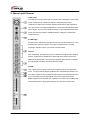
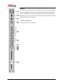
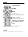
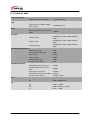
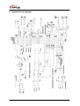
Manual
Smart M10/2
Smart M16/2
Inhaltsverzeichnis
1.
Safety instructions ............................................................................................................................ 3
1.1.
FOR SAFE AND EFFICIENT OPERATION ............................................................................ 3
2.
Mono Input Channel ......................................................................................................................... 5
3.
Stereo Input Channels...................................................................................................................... 8
4.
Master Section ............................................................................................................................... 10
5.
Technical data ................................................................................................................................ 12
6.
System block diagram .................................................................................................................... 13
2 / 14
1. Safety instructions
•
All modifications to the device will void the warranty.
•
Repairs are to carry out by skilled personnel only.
•
Use only fuses of the same type and original parts as spare parts.
•
Protect the unit from rain and humidity to avoid fire and electric shocks.
•
Make sure to unplug the power supply before opening the housing.
•
To avoid electric shocks, you should not remove the cover.
1.1. FOR SAFE AND EFFICIENT OPERATION
Be careful with heat and extreme temperature
Avoid exposing it to direct rays of the sun or near a heating appliance.
Not put it in a temperature bellow 32°F /0°C, or exceeding 104°F /40°C.
To avoid placing on un-stable location
Select a level and stable location to avoid vibration
Do not use chemicals or volatile liquids for cleaning
Use a clean dry cloth to wipe off the dust, or a wet soft cloth for stubborn dirt.
If out of work, contact sales agency immediately
Any troubles arose, remove the power plug soon, and contact with an engineer for repairing,
do not open the cabinet by yourself, it might result a danger of electric shock.
Take care with the power cable
Never pull the power cable to remove the plug from the receptacle, be sure
to hold the plug. When not using the device for an extended period of time, be sure to
disconnect the plug from the receptacle.
Transport
The console should be transported either free-standing or in an appropriate case. The console should
be protected during transport with foam or similar shock-absorbing materials. So you can avoid
damages.
3 / 14
Hearing
To avoid hearing damage, no sound system should be operated at high volume. This also applies to
monitoring systems that are in the vicinity of the ear, headphones and In-Ear-Monitor-Systems.
Important:
Damages caused by the disregard of this user manual are not subject to
warranty. The dealer will not accept liability for any resulting defects or
problems. Make sure the electrical connection is carried out by qualified
personnel. All electrical and mechanical connections have to be carried out
according to the European safety standards.
4 / 14
2. Mono Input Channel
1.MIC Input
The MIC input accepts XLR-type connectors and is designed to suit a wide
range of balanced or unbalanced signals. Professional dynamics,
condenser or ribbon mics are best, because these will be low impedance.
You can use low cost high-impedance mics, but level of background noise
will be higher. If you turn the Phantom power on (top right hand side of the
mixer) the socket provides a suitable powering voltage for professional
condenser mics.
2.LINE-Input
Accepts 3-pole TRS jacks. Use this input for sources other than mics, such
as keyboards, guitars or decks. The input is a balanced one. Unplug
anything in the MIC input if you want to use this socket.
3.Insert
The unbalanced, pre-EQ insert point is a break in the signal path, allowing
limiters, compressors, special EQ or other signal processing units to be
added in the signal path. The socket is bypassed. When a jack is inserted,
the signal path is broken, just before the EQ section.
4.GAIN
This control sets how much of the source signal is sent to the rest of the
mixer. Too high, and the signal will distort as it overloads the channel. Too
low, and the levels of any background hiss will be more noticeable and you
may not be able to get enough signal level to the output of the mixer.
Note: Equipment for domestic use, operates at a lower level (-10dBV) and
will therefore need a higher gain setting to give the same output level.
5 / 14
5. Equalizer
The EQ allows fine manipulation of the sound. This is useful in live
applications where the original signal is often far from ideal. Slight boosting
or cutting of particular voice frequencies can really make a difference.
There are three sections giving the sort of control usually only found on
much larger mixers. The EQ controls can have a dramatic effect, so use
them sparingly.
HF: Turn to the right to boost high (treble) frequencies above 12kHz
(Cymbals, vocals, electronic instruments) by up to 15dB. Turn to the left to
out by up to 15dB. Set the control in middle position when not required.
MID: There are two controls which work together to form a swept MID EQ.
The lower control provides 15dB of boost and cut, just like the HF EQ
control, but the frequency at which this occurs can be set by the upper
control over a range of 140Hz to 3kHz. This allows some truly creative
improvement of the signal in live situations, because this mid band covers
the range of most vocals. Set the control in middle position when not
required.
LF: Turn to the right to boost low (bass) frequencies below 60Hz by up to
15dB. Turn to the left to cut low frequencies by up to 15dB. Set the control
in middle position when not required.
6.AUX Sends
These are used to set up separate mixes for monitor mixes, effects or
recording. The combination of each AUX Send is mixed to the respective
AUX output.
7. PAN
This control sets the volume distribution to the R and L channels. If the
controller is set to the middle position, both sides get the same signal
component. By turning clockwise, the signal component of R is increased,
counterclockwise for L.
8.Mute
This button deactivates the respective channel.
9.Peak
This LED lights, when the signal is “clipping”.
6 / 14
10.SOLO
When the latching SOLO switch is pressed, the pre-fade, pre-mute signal is
fed to the headphones, control room output and meters, where it replaces
the mix. The SOLO LED on the master sections illuminates to warn that a
SOLO is active. This is a useful way of listening to any required input signal
without interrupting the main mix.
11.Input channel fader
It adjusts the level of the channel.
7 / 14
3. Stereo Input Channels
1.Monitor Outputs
These are balanced jack sockets.
2.AUX OUT (1&2)
These are balanced jack sockets for AUX 1&2.
3.Stereoeingänge
These are balanced TRS jack sockets.
4.GAIN
The Gain controls the level of the channel signal.
5.Equalizer
HF: Turn to the right to boost high (treble) frequencies above
12kHz (Cymbals, vocals, electronic instruments) by up to 15dB.
Turn to the left to out by up to 15dB. Set the control in middle
position when not required.
LF: Turn to the right to boost low (bass) frequencies below 60Hz
by up to 15dB. Turn to the left to cut low frequencies by up to
15dB. Set the control in middle position when not required.
6. AUX Sends
These are used to set up separate mixes for monitor mixes, effects
or recording. The combination of each AUX Send is mixed to the
respective AUX output.
7.PAN
This control sets the volume distribution to the R and L channels. If
the controller is set to the middle position, both sides get the same
signal component. By turning clockwise, the signal component of
R is increased, counterclockwise for L.
8. MUTE
This button deactivates the respective channel.
9.Peak
This LED lights, when the signal is “clipping”.
8 / 14
10.SOLO
When the latching SOLO switch is pressed, the pre-fade, pre-mute signal is
fed to the headphones, control room output and meters, where it replaces
the mix. The SOLO LED on the master sections illuminates to warn that a
SOLO is active. This is a useful way of listening to any required input signal
without interrupting the main mix.
11.Input channel fader
It adjusts the level of the channel.
9 / 14
4. Master Section
1.und 2. MIX OUTPUTS & INSERTS
The Mix L and R outputs are balanced XLR outputs. The
MIX Inserts are unbalanced sockets.
3.PLAYBACK IN
The two phone sockets are unbalanced L and R line-level
inputs, used for connecting a recording device.
4.REC OUT
These are two outputs to connect a recording device.
5.und 6.PHANTOM POWER
Man professional condenser mics need phantom power,
which is a method of sending a powering voltage down
the same wires as the mic signal. Press the switch (5.) to
enable the +48V power to all of the MIC inputs. The LED
(6.) lights when the power is active.
Note: Take care when using unbalanced mics which may
be damaged by the phantom power voltage. Balanced
dynamic mics can normally be used with phantom power
switched on (contact your microphone manufacturer for
guidance). Mics should always be plugged in, and all
output faders set to the minimum before switching the
phantom power on to avoid damage to external
equipment.
7. PHONES
The Phones output is a socket which ideally for
headphones of 200Ω or greater. 8Ω headphones are not recommended.
8.AUX TAPE
You can adjust the volume of AUX IN signal by this when connecting AUX IN.
9. PHONES LEVEL
This control sets the output level to the headphone. The monitor output levels are not affected.
10 / 14
10.REPEAT
This is used for adjusting frequency of echo repeat.
Since too much echo repeat may cause a howl. Please
adjust frequency properly.
11.und 12.AUX1;AUX2 OUT
This socket sends out the signal from AUX bus.
13.EFF/RETURN
This is used for adjusting volume of echo sound when
connecting sound to return jack.
14.;15.und 16.DELAY
This is used for adjusting the time interval of echo
repeat. The middle position (5) may be most effective.
17.Meters
The three-color peak reading meters normally show the
level of the Mix R und L outputs, giving you a constant
warning of excessive peaks in the signal which might
cause overloading.
When any SOLO switch is pressed, the meters switch
to show the selected Solo signal on both meters, in
mono. The SOLO LED also lights.
18. Master Fader
The master faders set the final of the mix outputs.
These should normally be set to the “0” mark if the input
gain settings have been correctly set.
11 / 14
5. Technical data
Frquency response
MIC/Line input to any output
+/- 20Hz bis 20kHz
MIC sensitivity +30dBu-+20dBu
@all outputs
< 0,008% bei 1kHz
THD
Noise
MIC input (Max. Gain, measured
-128dBu
22Hz)
Crosstalk
<90dB 20Hz to 10HZ; <80dB 10kHz to
20kHz
<90dB 20Hz to 10HZ; <80dB 10kHz to
20kHz
<90dB 20Hz to 10HZ; <80dB 10kHz to
20kHz
Channel mute
Fader Cut-Off
Routing isolation
Input&output impedances
Microphone input
Mono channel Line input
Stereo input
Stereo Returns
Headphones Output
All other audio output
Input&output levels
Microphone max. input level
Mono channel max line input
level
Stereo max. input level
Headphones output (into 200Ω)
All other audio output
Filter
HP
EQ
HF
MF
LF
12 / 14
~2kΩ
>40kΩ
>30kΩ
>10kΩ
~40kΩ
75Ω
+12dBu
+38dBu
+21dBu
150mW
+21dBu in 10kΩ
100Hz, 18dB/Octave
12kHz, +/-15dB
240Hz to 60kHz, +/-15dB
60Hz, +/-15dB
6. System block diagram
13 / 14
Importeur:
B & K Braun GmbH
Industriestraße 2
D-76307 Karlsbad
www.bkbraun.com
[email protected]
14 / 14


![User Manual PS 260 [ASL]](http://vs1.manualzilla.com/store/data/005875222_1-79f7ffd37f8e6cc3732f57605cc0b82b-150x150.png)