1
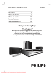
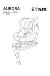
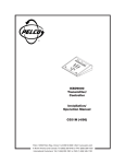
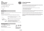
Yale H48000-960H DVR
*Also supports H88000-960H
User manual
Please visit www.yale.co.uk for more information
Introduction
Contents
Thank you for choosing the Yale H48000-960H
DVR recording unit. The unit has been designed
to meet the demands of the basic to advanced
users.
Connecting your DVR
2
Basic DVR operation
4
DVR Main Menu in details
8
Controlling Yale Alarm & Smart Lock
26
Connecting your DVR to the internet
28
Guarantee statement
36
These are the basic operating and installation
instructions and our advanced version is available
to download from www.Yale.co.uk or email info@
yale.co.uk to receive in the post.
The default settings of the DVR will help cover
most basic installation requirements.
Before installing anything we highly recommend
to connect the cameras and DVR and text the
system.
Display extreme caution when using ladders or
steps, please follow manufacturer’s instructions.
Be careful when using hand and power tools
and follow the manufacturer’s guidelines when
using them. Take care that the correct tools are
used. Wear goggles or protective clothing where
required.
Requirements
A broadband router with one free ethernet port is
required. Router must support DHCP and UPnP in
order to allow connections.
iOS 7+ or Android 4.1+ required for remote app
viewing. Mobile data speed will effect quality and
connection.
Information and illustrations are subject to change within this
document. Yale reserves the right to alter the specification and
product design at anytime without notice. Yale® is a registered
trademark. © 2014 ASSA ABLOY. All rights reserved.
1
Connecting your DVR
3
5
2
4
8 9
*
1
*
6
7
10
H48000-960H = 4 video channels
H88000-960H = 8 video channels
1. BNC Video Inputs 1 – 4: These are the video inputs used when connecting your BNC cameras. These
are numbered 1 – 4 (or 8 in H88000-960H) as they would appear on the screen of your DVR.
2. Audio Output: A standard line level audio output. You may experience delay in replay time.
3. BNC Video Output: This is for connecting your DVR to a suitable Monitor or TV with BNC or RCA Input.
4. HDMI Output: For connecting a television or PC Monitor with a HDMI cable.
5. VGA Output: For connecting a television or PC Monitor with a VGA cable (not supplied).
6. Audio Input: These will accept a standard in-line audio microphone device.
7. USB Ports: The top port is used for connecting storage devices. The bottom port is for connection of the
mouse (supplied).
8. Network Port: You are able to connect the DVR to a network router or switch. This will allow the option of
using online features (suitable broadband connection required).
9. RS485 controller port: For use with RS485 supported PTZ camera.
10. 12V DC Power input: This is where you connect the DVR power adapter. DO NOT switch on power until
all leads are connected.
2
TV/
Monitor
DVR
Adaptor
DVR
15m
BNC/DC cable
Connect
to multiple
cameras
Camera
Adaptor
*
*
H48000-960H = 4 video channels
H88000-960H = 8 video channels
Installation guideline
Please ensure the system is fully working prior to installation. Connect all the
cameras using the supplied cables and make sure it operates as intended.
Remember the DVR unit is most likely to be left on 24 hours a day, 7 days a week. Please bear this in mind when
choosing installation location.
Route the camera cable away from sources of electromagnetic interference, mains cable and heat source.
Please only use the power adapter supplied.
Install DVR in a well vented area.
DO NOT expose the DVR to moisture or water. Avoid dusty or dirty locations.
DO NOT open the DVR case unless you are requiring exchanging the hard drive.
DO NOT open the case to your DVR whist your DVR is plugged in and switched on.
DO NOT cut or adjust any cable for any reason.
DO NOT place the DVR in areas where it may experience sudden bumps shocks or movements.
DO NOT apply excessive force to the camera cable during installation. This may damage the cable resulting in loss/
intermittent video signal.
DO NOT apply pressure to the cable connector’s neck. This may damage it’s internal soldering.
3
2
Basic DVR operation
The only way to start using your DVR and navigating through the DVR menu’s is to connect and use the
provided Yale mouse. We have designed the system for mouse friendly operation.
The controls are extremely simple to remember.
Left Click – Selects the item covered by mouse pointer
Right Click – Back or escape function allows you to go back to previous menu or screen
Scroll Wheel – Allows you to flick through the cameras on full screen
Quick Start Menu
When you turn the DVR system for the first time the quick start menu will appear in the centre of the screen.
Enable Yale Cloud if you would like remote viewing via internet. Click Next to continue.
You will be presented with a QR code for app registration. You can exit this screen if you are not ready to
set-up your app. You can access this QR code by choosing “Quick start” under the right click menu.
*For details on app set-up, please visit www.yale.co.uk under “CCTV” and then “Support”.
You should now have a spilt screen image of the 4 connected cameras (if no camera is connected you will
see a black screen as above)
4
Main Menu
To access the main menu, right hand click on the USB Mouse. A list of options will appear. Select the top
option Main Menu.
The first thing you will need to do is to set up the time and date on your DVR.
Move your connected mouse to the Setting tab. Select the General option
5
Here you will be able to set the time and date on your DVR system.
Move your mouse over the required section you wish to change and left click.
A keypad will appear allowing you to change the required time or date number.
In the General menu you will also be able to adjust your Time Zone (on support model) and Time Format
between 12/24 hour.
The DVR also supports multi language. This can also be changed from the General Menu.
6
7
3
DVR Main Menu in details
Under the main menu:
Record: Configure recording schedules, playback/backup old recordings and define video encoding
quality.
Detection: Records and alerts when motion is detected, camera lens is obstructed or the camera cable is
cut.
Settings: General settings, internet & cloud settings, screen settings, user password settings etc.
Professional: Advanced settings and professional features
Yale Alarm System: When used with EF-USBDVR (CCTV/Alarm adaptor), this enables control of Yale alarm
and lock.
8
Record
REC Config
Select the Rec Config option. Here you will be able to set your DVR to different recording formats
(Schedule, Manual or Stop)
First select the Channel you wish to configure.
Redundancy: recording mirror back up on a second hard drive. Since this model only supports a single
drive, this should remain un-selected.
Length: recording clip size. We recommend using the default 60 minutes.
Pre-record: video pre-recording. We recommend using the default 5 seconds.
Select the mode you wish that Channel / Camera to perform.
Schedule – Timed recording or motion detection
Manual – Continuous recording. By default, the oldest recording will be overwritten.
Stop – Do Not record (Only allow you to view live footage and unable to playback)
If you have selected Schedule recording you will then need to day of the week or select all.
You are able to select 4 different time periods throughout the 24 hour period.
By each time period you will need to select regular or detect.
Regular – Continuous Recording
Detect - Motion Detection recording only
Once you have configured this section click the OK button to save your setting. The system is now set-up to
record automatically according to your setting. You can view and backup past recording via the Playback
option.
9
Playback
This option allows you to view past recording and to make a backup (onto USB flash drive) as required.
1) Display past recording. Click to select camera for backup operations and double click for full screen
view.
2) Play or pause recording playback. Recording must be paused before changing recording dates and
cameras.
3) With a camera selected and video playing back, click to start backup of recording. You can click on the
time line bar (4) to jump to the end point. Click again to stop recording. Press the hard drive button on the
right to backup onto the USB drive (please ensure USB flash drive is plugged in).
4) This shows the time line of recording. Use the mouse to click on any point to view recorded event. Grey
indicates no recording, Green indicates continuous recording and Red indicates recording triggered by
motion detection. Use the mouse scroll button to zoom in/out of the time line.
5) Select camera to display. You need to pause playback before you can make such selection.
6) Select date for playback. You need to pause playback before you can make such selection.
10
Backup
Allow user to backup their video recording onto a USB flash drive
On the back of the DVR is a USB port. Insert a USB flash drive and press the detect button. The USB flash
drive will now have been detected and appear within the box (If the pen drive is not detected the DVR will
need to be re-started with the USB drive still inserted)
Once the USB drive is detected you will need to click the backup button. It will prompt you to select a clip
based on dates for backing up. NOTE: if you wish to view the backup in PC, please select Backup format
as AVI instead of H264.
Burning – This function is not available on this model
Erase – This will allow you to erase any current files on your USB flash drive
Stop – will stop any ongoing backup process
Please ensure you allow the DVR to complete the backup before removing the USB flash drive, failure to do
so could result in the system crashing.
11
Video encode
Allows user to change the hard drive recording and internet streaming video quality for every camera
channel.
Hard drive recording quality (Left column): This effects the DVR recording quality. Higher quality will
consume more hard drive space, whilst lower quality will result in longer overall recording time before the
hard drive is full.
Internet streaming quality (Right column): This effects the image quality when viewed via internet. Higher
quality will result in slower streaming and may cause instability. Lower quality will result in more fluid and
stable playback.
Compression: Please use the default settings.
Resolutions: 960H= 960x576, D1= 704x576, HD1= 704x288, CIF= 352 x 288, QCIF= 176x144
Frame Rate: Higher frame rate results in more fluid motions, however it will also take up more space/
bandwidth.
Bit rate type: Unless you have specific reason of using Constant bit rate (CBR), please use the default
Variable bit rate (VBR) for optimal results. VBR allows the encoding engine to vary based upon the motion
level of the actual recording.
Quality: Better quality will result in taking up more hard drive space and internet bandwidth.
I Frame interval: Number of I Frame in the clip. Higher implies better quality. Please use the default value of
2.
12
Video/Audio: Tick to enable video (left box) and audio (right box) recording.
Detection
Motion Detect
Here you will be able to set the DVR to active motion recording by setting a region area on the picture.
Ideally, focus the motion detection on a doorway, window, gate or driveway.
Firstly you will need to select the camera channel you wish to enable (dropdown menu). Once you have
selected the channel you will need to check the ENABLE box. Once you have selected the Channel you
want to set, you can set a region you wish to be covered by pressing the SET icon.
Here the Channel you have selected will appear on the screen highlighted in red squares (see below)
The area which is highlighted in red is the area which will trigger the activation. To focus on a window simply
click the left button on the mouse to turn the square clear. By turning these clear this will NOT activate the
motion detection function.
13
Once you have selected the area click the right mouse button to return to the previous screen.
Now you can set the time period you wish this motion activation to take place. Click the SET button next to
the PERIOD heading
Here you can select day and time period you wish the system to look for motion detection. The system will
be defaulted to 24 hours a day 7 days a week detection.
Click the right button on the mouse to return to the previous menu.
RECORD CHANNEL: is a feature which you could set the DVR to record a number of cameras should 1
channel be activated. Should the motion detection on Channel 1 be activated, you can set the system
to start recording cameras on different channels without it needing to be activated, helping to give you
maximum coverage.
TOUR: is similar to above but this will record and rotate through the channels selected.
The remaining 4 icons are used for notifying you of the activation
SHOW MESSAGE: This will allow a message to pop up on your screen to indicate activation has taken
place
BUZZER: This will activate a buzzer sound on the DVR to indicate activation has taken place
SEND EMAIL: This will instruct the DVR to email you upon activation. Email set up is completed in Settings
-> Yale Cloud -> Email option.
FTP UPLOAD: This will allow you to store footage on a different remote location. Set up is completed in
Settings-> Yale Cloud -> FTP option.
14
Covered Lens
This function helps detect any deliberate covering of the cameras lens to prevent recording of the desired
image.
Firstly you will need to select the camera channel you wish to enable (dropdown menu). Once you have
selected the channel you will need to check the ENABLE box.
Period: Here you can select day and time period you wish the system to look for camera covered detection.
The system will be defaulted to 24 hours a day 7 days a week detection.
RECORD CHANNEL: is a feature which you could set the DVR to record a number of cameras should 1
channel be activated. Should the camera covered detection on Channel 1 be activated you can set the
system to start recording cameras on different channels without it needing to be activated, helping to give
you maximum coverage.
TOUR: is similar to above but this will record and rotate through the channels selected.
The remaining 4 icons are used for notifying you of the activation
SHOW MESSAGE: This will allow a message to pop up on your screen to indicate activation has taken
place
BUZZER: This will activate a buzzer sound on the DVR to indicate activation has taken place
SEND EMAIL: This will instruct the DVR to email you upon activation. Email set up is completed in Settings
-> Yale Cloud -> Email option.
FTP UPLOAD: This will allow you to store footage on a different remote location. Set up is completed in
Settings-> Yale Cloud -> FTP option.
15
Signal Loss
This function alerts you should any signal loss happen to any camera. This can be caused by cutting the
cameras cable, turning off the power supply to the camera or disconnecting from the DVR.
Firstly you will need to select the camera channel you wish to enable (dropdown menu). Once you have
selected the channel you will need to check the ENABLE box.
Period: Here you can select day and time period you wish the system to look for signal loss detection. The
system will be defaulted to 24 hours a day 7 days a week detection.
RECORD CHANNEL: is a feature which you could set the DVR to record a number of cameras should 1
channel be activated. Should the signal loss detection on Channel 1 be activated you can set the system
to start recording cameras on different channels without it needing to be activated, helping to give you
maximum coverage.
TOUR: is similar to above but this will record and rotate through the channels selected.
The remaining 4 icons are used for notifying you of the activation
SHOW MESSAGE: This will allow a message to pop up on your screen to indicate activation has taken
place
BUZZER: This will activate a buzzer sound on the DVR to indicate activation has taken place
SEND EMAIL: This will instruct the DVR to email you upon activation. Email set up is completed in Settings
-> Yale Cloud -> Email option.
FTP UPLOAD: This will allow you to store footage on a different remote location. Set up is completed in
Settings-> Yale Cloud -> FTP option.
16
Settings
General
You will be able to change the systems Time, Date, Language, DVR Name from this menu.
Simply click on the option you wish to change and amend to the desired details you require. Options
include:
HDD Full: This allows you to choose if you want the DVR to overwrite the oldest data once the Hard Drive is
full or to stop recording.
DVR No: You are able to number each DVR should you have more than 1 DVR on location
Video Standard: Choose between PAL & NTSC
Auto logout: You can enter the amount of minutes the unit can be unused before it locks the screen.
Password is then needed to gain access into the menu.
Machine Name: You can name your DVR anything you wish, popular names range from “HOME DVR”,
“WORK DVR”, “OFFICE” and “SHOP”.
Local Network
You should not have the need to change this setting unless your network does not support DHCP and
required manual network configuration. See section 5 for further information concerning internet
connection.
Yale Cloud
Tools to set up email, FTP and DDNS. See section 5 for further information concerning internet
connection.
17
Screen Display
In this menu you will be able to change display size. Here you will also have the ability to change the
display names of the cameras and be able to black out parts of an image for areas you do not wish to
record such as moving trees, main roads etc.
Channel Title: Here you can change the name of each camera which is displayed on the screen from your
DVR. Click Set to bring up a submenu with camera names (default cam 01, 02, 03 ... etc). Common name
changes include GARDEN, DRIVEWAY, FRONTDOOR, SHED, PLAYROOM. Simply Click on the Channel
you wish to change the name of and the on-screen keyboard will appear. Once completed click OK and the
new details will be saved.
Frame Display: Displays live Time and Date
Channel Title: Name you have given to each camera or the default CAM01, CAM02 etc
Record status: Indicates if the DVR is recording the Channel
Alarm status: Indicates if one of the Detection settings have been activated
Transparency: Change opacity of the menu against the background camera picture.
Resolution: Here you can change the display output screen resolution. Please check the resolution
supported by your display. Typical HD 1080 TV via HDMI will support 1920x1080 (best resolutions).
Connecting via VGA cable to a small PC monitor often means it can only support 1024x768 or 1280x1024.
Region Cover: You can black out areas on screen (for privacy reason). Choose a camera/channel and tick
this option. You can now black out a maximum of 4 regions.
Time Display and Channel title positioning: Click set to define positioning of time stamp and title in your
camera image.
18
User Account
You can change your password in this section. You can also add more users with access rights assignment.
If you would like to connect this DVR to the internet it is critical that a password is setup for your system.
Please change the password by clicking Modify Pwd on the right hand side. Leave “Old” as blank (if you
have not changed it), and enter the new password.
For power user, you can also create new user groups under this options. Please secure all newly created
user groups to ensure security is not compromised.
PTZ Config
If you use a PTZ camera (with camera communicating cable connected to RS485 port), please set the PTZ
parameter to match your camera’s specification. Please check with your camera manufacturer for details.
The left column is to set-up parameter for the camera, while the right column is to set-up for PTZ controllers.
19
Tour
You can set your screen to auto-scroll between different cameras. This is especially useful for guard station.
Tick to enable Tour function and set which cameras to view and it’s interval. For example, under View 1 (one
camera full screen) if you select 1, 3 and 4, for 5 seconds, it will show cam 1 for 5 seconds and move to
cam 3 and 4 for 5 seconds each.
Under Alarm Tour type, upon a detection event it will show that camera for the stated interval.
Logout
This option allows you to Logout (require password to access main menu again), Shutdown or Reboot the
system.
20
Professional
For typical users, these settings can be left at default.
HDD Manage, Info & Faults
These options allows you to make a drive read only, partition & format your hard drive, see its status and
choose what to do in the event of faults.
Bits Per Sec
For those interested in calculating the exact memory space their recording will occupy, this option shows
you live bitrate for such calculation. Please note that bitrate will vary depending on the image content (i.e. a
busy moving image will be have a higher bitrate than a white static wall)
Online User
This option allows you to see if there is any internet users connected to the system.
21
Upgrade
This option allows you to upgrade your DVR firmware. Put the firmware file on a FAT format blank USB
flash drive (do not place the file in any folders). Insert the drive into the DVR’s USB port. Select this option
(Upgrade) and it should detect your drive and the file. In the event that it is not detected, close the window
and try again. Once the file is located, click the Upgrade button to start upgrading.
WARNING: Do not disrupt this process and ensure the DVR has a continued power supply. When it finishes
the system will reboot. The process may take as long as an hour in some cases. Disrupting this process will
render this machine permanently inoperable. Please seek professional advice prior to upgrading.
Auto Maintain
This option allows you to periodically reboot your DVR and to delete old files. Rebooting will extend the DVR
and its mechanical hard drive’s life span. Default is set to reboot every week on Wednesday 3 am.
22
Import/Export
This option allows you to save or load log & DVR configuration onto a USB flash drive.
Factory Reset
This option allows you to reset some DVR configurations back to default factory setting.
23
System Info
This information is useful for our customer services in trouble shooting your DVR system.
Log
This option allows you to see the historic log of this DVR. It is searchable by date and event type.
24
DVR/NVR Mode
This DVR is also a NVR that supports ONVIF IP camera. You can configure this NVR to receive/record
ONVIF standard IP camera on your local network. To enable the hybrid/NVR function, you must first select a
channel type. You can set it to recognise a mixture of analogue BNC cameras with some IP cameras, or you
can have it purely receiving IP cameras.
Once you set the system to receive IP cameras, you must locate and manually connect these IP cameras.
25
4
Controlling Yale Alarm & Smart Lock
By using the USB dongle (model: EF-USBDVR), the user can control their Yale Easy Fit alarm and Yale
Smart lock via this DVR system. Compatible with: EF-Kit1, EF-Kit2, EF-Kit3, EF-Kit4, Yale Keyfree lock.
Please ensure you power is off and reboot the DVR after you connect the USB dongle in a spare USB
socket (on the rear). The USB dongle is recognised by the DVR automatically. You will now need to pair the
USB dongle with your Easy Fit alarm system and Smart Lock. Since this is a wireless interface, you may
need to move the DVR/USB dongle closer to the alarm/lock to allow optimal operation.
Pairing with your Easy Fit alarm
Siren based system (EF-kit1, EF-kit4)
You will need to firstly enter learn mode on your system.
Using your alarm keypad:
Press Panic button A followed by the pincode (Indicated by a continuously flashing LED.)
Press Panic button A followed by 2 (The siren will beep in response.)
Press Panic button A followed by 4 . (The siren will beep and flash in response.)
You are now in alarm learn mode.
Press the two buttons (one by one) on the USB dongle to trigger learning-in signals. The USB dongle will
transmit keyfob and PIR signals to your alarm system. The siren will beep and flash when each button is
pressed.
When both buttons have been learnt in:
Press Panic button A and 5 to quit learn mode.
Press Panic button A and 3 to rearm tamper protection.
Press Disarm twice to exit (The alarm keypad LED will now stop flashing.)
For more information, please refer to your alarm manual section: Adding accessories to an existing system
Telecommunicating alarm system (EF-Kit2)
Using your alarm control panel:
From the programming menu of the control unit, select ‘Devices’ and press ok, select ‘Add Device’ and
press ok again.
Press the one of two buttons on the USB dongle to trigger learning-in signals. The USB dongle will transmit
keyfob signal (button 1) and PIR signal (button 2) to your alarm system. After each press, you will need to
confirm your selection on the alarm panel before moving onto the next button.
When both buttons have been learnt in, exit programming menu and back to standby mode.
For more information, please refer to your alarm manual section: Adding and using accessories
26
SmartPhone alarm system (EF-Kit3)
Press and hold the learn button (on the rear of the alarm panel) for at least 3 seconds. Led 1 will now flash
and beep to indicate that you have entered learn mode.
Press the two buttons (one by one) on the USB dongle to trigger learning-in signals. The USB dongle will
transmit keyfob signal (button 1) and PIR signal (button 2) to your alarm system. The siren will beep and
flash when each button is pressed.
When both buttons have been learnt in, press and hold the alarm panel learn button for at least 3 seconds.
The LED should now stop flashing and entered standby mode.
For more information, please refer to your alarm manual section: Adding and using accessories
Pairing with your Yale Smart Lock
Note: Please check with your lock installer that the lock is fitted with the correct module for this
USB dongle.
Press the “i” button on your Smart lock. The lock is now in learn mode. Press and hold the USB dongle DDL
button for at least 5 seconds. The lock will beep to confirm successful learnt-in. Press the “i” button to exit
learn mode.
Operation
Arm: Press the arm button on the DVR or mobile app. The alarm will now enter Full arm mode.
Home Arm: Press the home arm button on the DVR or mobile app. The alarm will now enter Home arm
mode.
Disarm: Press the disarm button on the DVR or mobile app. The alarm will now be disarmed.
Door Unlock: Press the unlock button on the DVR or mobile app. The lock will now open.
Intelligent: Please ignore. This is a reserved function for future software updates.
Camera signal loss: With Signal Loss option (Main menu -> Detection -> Signal Loss) enabled,
disconnection of camera cable will trigger alarm during arm mode.
27
5
Connecting your DVR to the internet
In order to connect your Yale DVR to the internet for remote internet viewing, you will need the following:
Home Network environment:
•
•
•
•
•
You will need a fixed-line broadband router with fast internet access (ideally 10Mps+).
The router needs to have at least one spare wired network socket (connecting to the Yale DVR).
Access to the local administration screen on your router. This allows trouble shooting in the event of
issues related to firewall and port settings. Please ask your router manufacturer for more information.
Most home network uses dynamic IP addresses. Performance will improve if the network uses Static IP
address (some ISP provides this as an option).
If you use the default automatic setting (auto-connection to the Yale Cloud), your router’s DHCP must be
enabled.
Please note: This DVR may not perform optimally in some corporate environments. Large
company network normally uses Symmetric NAT and this will degrade the connectivity, speed
and performance of certain remote operations.
Remote viewing via smart phone:
•
•
•
•
Please search and download “Yale Easy Fit DVR” app from iOS iphone app store and Google Play
store.
Compatible with iOS 7+ and Android 4.1+
Minimum recommended resolution 600 x 900
For optimal performance, your mobile phone need to have fast internet access (at least 3G+ with good
signal strength). Due to many mobile phone operators adopting CGN (carrier grade NAT), you may
find that your connection works much faster when you are connected to a home WiFi network. This is
because CGN uses Symmetric NAT and sometimes resulted in reduced performance
Remote viewing via Internet Explorer browser:
•
•
•
PC with broadband internet
Internet Explorer 10 or above
Requires unsigned active-X enabled (you can also download the active X software from our website)
Local network viewing via Internet explorer browser:
•
•
•
28
PC with connection to the same local network (as the DVR)
Internet Explorer 10 or above
Requires unsigned active-X enabled (you can also download the active X software from our website)
Choosing a method for connecting to the internet.
There are two ways to connect your DVR to the internet, either via Port forwarding or using the Yale cloud
server. For ease of use, we have enabled Yale cloud as the default connection method. However due to
superior reliability and performance, we would recommend using Port forwarding for technically adept
users.
Problem with NAT traversal
Yale cloud relies on NAT traversal to gain access to your DVR from the outside. While in many cases
it works perfectly, this technology’s limitation also means some network environment may fail or suffer
performance issues. This is to do with the type of NAT (network address translation) implemented by your
network.
Most home networks use Full cone, Restricted cone and Port restricted cone NAT. These three types of
NAT will work with our NAT traversal method. However any network that uses symmetric NAT (i.e. Corporate
network and CGN 3G/4G phone network) may experience connection related issues. This limitation applies
to both the DVR network environment as well as the remote viewing network environment (i.e. Your mobile
phone).
Ideal operation environment for Yale cloud is when the DVR is connected to a full cone home network
environment, and the remote viewing phone is connected via Wi-Fi to a full cone home network.
1) Set-up using Port forwarding method
This is the most reliable method for internet access. For the ultimate speed and reliability we advise
users to use static IP address. Not all internet service providers (ISP) provide static IP address,
and the user will be expected to pay a small monthly fee for such service- please check with your
provider accordingly. Alternatively our DVR support a number of Paid and free DDNS service should
you be using Dynamic IP address.
Static Vs. Dynamic IP address
IP address is similar to your physical postal address; it acts as your unique contact ID when you are
communicating with the wider world. In the ideal world, every home will have its own unique and
permanent address, i.e. Static IP address. However due to a shortage of IP address range (V4), it
may not be practical to assign a unique and globally accessible IP address to each customer that
is connected to the internet. Internet service providers usually own a range of static IP addresses,
and it will dynamically assign these addresses to online users. Once the user is offline, this static IP
address is randomly given to another online users and reused in this way. This is known as dynamic
IP address. The main problem with dynamic IP address comes when you try to access your machine
remotely. Since your IP address may have randomly changed since you last noted, you do not have
the up-to-date address to access your system. One way to resolve that is by using a DDNS service.
It acts like a PO box service, and you can configure your machine to automatically inform this central
server of any changes to your dynamic IP address. By accessing your DDNS service using a URL
handle, you will be automatically diverted to the correct IP address of your machine.
Setting up port forwarding if your router supports UPNP:
1) Please ensure your router UPNP option is enabled. Please check with your router manufacturer on how to
do this.
2) Enable UPNP on your DVR: Menu -> Settings -> Yale Cloud -> UPnP (enable)
Manual port forwarding:
Difference router manufacturer may name this setting differently. Some may call it Game and Application
sharing, while others may refer to it as Port forwarding etc. Please check with your router manufacturer
29
on how to do this. You will need to enable TCP/UDP port forwarding of the two ports, 80 and 34567. This
means whenever you try to access your router from the outside, any call to the port 80 and 34567 will be
automatically forwarded to your DVR.
Setting up DDNS for dynamic IP address:
Should you have a static IP address, you can simply access your DVR using this information. For the
majority of users out there, it is likely that you have dynamic IP address and need to set-up DDNS in order
to access the system remotely. You can either do this on your router (please check with router manufacturer)
or on our DVR. Please go to the option: Menu -> Settings -> Yale Cloud -> DDNS. Please choose one of the
supported DDNS service. You will need to register with this DDNS service before it can be used. Some of
these DDNS requires a yearly fee. We will extend the list of supported DDNS in our future firmware updates.
2) Setting up email alert and FTP upload
Go to menu -> Settings -> Yale Cloud and select email and FTP option. Setting up email alert upon motion
triggers. You will need to know your email’s SMTP server and other account information. SSL supported.
Please ask your email provider for the required information.
Setting up FTP to upload video motion recordings to a remote location. You will need to know your FTP
server IP and FTP account information. Please ask your FTP provider for the required information.
30
3) Remote viewing via internet explorer web browser
You will need to download & install the active X software from our website www.yale.co.uk (under CCTV)
before you can run our software on your web browser.
Enter the IP address http://54.76.132.77 on an internet explorer browser (It does not work in Safari, Chrome
or Firefox). It may prompt you to accept Active X and you need to click accept to proceed. You will now
see a black login screen. Enter your DVR serial number (it can be found in Main menu -> Professional ->
System Info -> Serial no), user name, password and verification code to login. This serial number is not
the number found on the sticker at the bottom of the DVR.
1) Play back camera using main stream or extra stream (lower quality)
2) Open up DVR Main Menu option.
3) Select camera for operation, or double click for full screen.
4) PTZ function if PTZ camera is present and supported.
5) On-screen colour correction.
31
4) Local viewing via internet explorer web browser
You will need to download & install the active X software from our website www.yale.co.uk (under CCTV)
before you can run our software on your web browser.
Find your DVR IP address by going to Main Menu -> Settings -> Local Network -> IP address. Enter this IP
address on an internet explorer browser (It does not work in Safari, Chrome or Firefox). It may prompt you to
accept Active X and you need to click accept to proceed. You will now see a black login screen. Enter your
user name and password to login.
1) Play back camera using main stream or extra stream (lower quality)
2) Open up DVR Main Menu option.
3) Select camera for operation, or double click for full screen.
4) PTZ function if PTZ camera is present and supported.
5) On-screen colour correction.
32
5) Remote viewing via Mobile phone app
You can view your DVR remotely using the Yale CCTV app. Please download this app from the iOS
app store and Google Play store. Search “Yale CCTV”. Please make sure you have fast mobile internet
connection, and preferably Wi-Fi connection to ensure the app runs smoothly. Upon launching the app:
No DVR registered: Already registered:
-Using Serial number (QR code)
-Using IP address (port forward)
-Select an existing DVR to view
Please name your DVR, followed
by pressing the QR code icon (on
the right side of Serial No.). This
will open up a scanner for you to
scan the QR code on your DVR
screen (see page 4). Enter your
User name (default=admin)and
password. Please ensure you set
up a password on your DVR.
Press Save once finished.
Please name your DVR, followed
by entering your static IP or URL
from your DDNS server. Enter
your User name (default=admin)
and password. Please ensure
you set up a password on your
DVR.
Press Save once finished.
Choose one of the existing DVR
to connect or you can add a new
DVR. You can also delete and
edit your registered DVR.
You will now see the main console screen showing the first camera. If you use QR code for connection, the
image may take more than 10 seconds to load up. Connecting via IP address and DDNS URL will be faster.
If the DVR failed to load or the camera cannot be connected, please restart the app or press the camera
icon within the picture frame to reload. Please also check and ensure your DVR is connected to the internet.
33
1) Press and drag left or right (anywhere within the picture frame) to scroll between cameras.
2) Press an drag left or right (start from the edge of the phone’s screen) to scroll between channels, Yale
Alarm control (for use with USB link adaptor) and Pan-tilt-zoom camera control (optional).
3) Press the Yale logo to access the menu system.
1) “DVR Settings” allows you to remotely configure some of the DVR settings.
2) “App Configuration” changes the local app behaviour. You can set the app to display 4 cameras at the
same time (may require faster internet connections).
34
ASSA ABLOY Ltd.
School Street, Willenhall
West Midlands
England, WV13 3PW
ASSA ABLOY Ltd.
School Street
Willenhall
West Midlands
England
WV13 3PW
Model:
Model:
HSA3400
D46000-D1
HSA3400
HSA3020
H48000-960H
HSA3020
HSA3060
H88000-960H
HSA3060
HSA3010
SCD-70B20B
HSA3010
HSA3050
SCH-70D20A
HSA3050
HSA3045
SCH-85B40B
HSA3045
AC-100W
HSA3080
HSA3080
AC-101W
HSA3030
HSA3030
HSA3070
HSA3070
is (are) in conformity with the following CE and RoHS standards:
EN55022:2006+A1: 2007+A2: 2010;
EN55024:2010
EN50130-4:2011;
EN61000-3-2:2006+A1:2009+A2:2009;
EN61000-3-3: 2008;
EN61000-4-2: 2009:
EN61000-4-3:2006+A1:2008+A2:2010
EN61000-4-4:2012;
EN61000-4-5:2006;
EN61000-4-6:2014;
EN61000-4-8:2010;
EN61000-4-11:2004;
EN60950-1:2006+A11:2009+A1:2010+A12:2011
2011/65/EU (RoHS)
2006/66/EC (RoHS)
IEC 62321:2008 (RoHS)
John Ward
Director
Date:
29/05/2014
On behalf of ASSA ABLOY Ltd.
17
3517
All devices
EMC
Power supply 3 x AAA alkaline cells. 3
Passive infra red (PIR) detector
years typical domestic service life
All devices
Passive
infra red (PIR) detector
2 Year Guarantee
Statement
Alarm processing Microprocessor
dual edge sequential pulse
EMC controlled
Tested to ETS 300 683
count with pulse length discrimination
Radio Components tested to EN
Tested
to433.92MHz
ETS 300 683
Radio
AM transmitter
300 220-1
Radio
Components
EN
Power
supply 4.5V,tested
3 x AAtoalkaline
cells.
300 220-1
3 years typical domestic service life, 1Environmental conditions
minute
sleep timer
This product is guaranteed for consumers against faulty
workmanship,
Environmental
conditions
-10°C to 40°C, relative humidity
Movement
detection range 15m, 110°
materials and function for a period of 2 years from the
date of purchase
-10°C to 40°C,
relative humidity
70%
non-condensing
for alland
units
providing
the full installation
maintenance instructions
are followed.
70%
non-condensing
forcontact
all units
Door/window
except
external
siren.
Siren: -20°C
Pleasethe
keep
your proof
of purchase
safe, this
must
be submitted when
claim under
this guarantee.
except the external siren. Siren: -20°C
tomaking
50°C, arelative
humidity
95% nonRadio Microprocessor controlled
to 50°C, relative humidity 95% noncondensing
433.92MHz
transmitter
Please note that it is a condition of this guarantee
that yourAM
Yale
condensing
Power supply 3V, 2 x AAA alkaline cells. 3
product:
Radio operational range
years typical domestic service life
Radio operational range
30m in a typical domestic
• Hasbeencorrectlyinstalledandmaintainedinaccordancewiththe
30m
in a typical
domestic
installation,
range can
vary depending
Yale installation
and maintenance
instructions
provided
to you
at
Smoke
detector
installation, range can vary depending
on building
the time construction,
of purchase. device
Radioconstruction,
Microprocessor
controlled
• Hasnotbeenmodifiedordamagedinanyway.
on building
device
positions
and RF environment
433.92MHz AM transmitter
• Hasnotbeensubjectedtounauthorizedrepairs.
positions and RF environment
Power supply 6V, 4 x AAA alkaline cells. 3
Housings ABS/polycarbonate
years
typical
domestic
service life
Yale are responsible under this guarantee for
repairing
the
product
or
Housings
ABS/polycarbonate
replacing the product as we deem necessary. If there is fault with the
Siren
product, please contact Customer Services on 01902
364647,
who control
remote
Siren Keyfob
willgiveyouthenameofanexpertandconfirmwhatyouneedtodo
Siren output 104dBA sound pressure @
to make
a claim under this guarantee.
Radio104dBA
Microprocessor
controlled
1m
minimum
Siren output
sound pressure
@
433.92MHz AM transmitter
Radio 433.92MHz AM super heterodyne 1m minimum
Powerorsupply
12V,
23A/MN21
alkaline
Please do
notjamming
carry out detection
any repairs without Radio
our authority
by using
an
receiver
with
433.92MHz
AM
super
heterodyne
miniature
"lighter"
battery. 3 years
unauthorised
repairs
or other
carried
outjamming
without
our
Power
supply 6V,expert.
4 x DAny
alkaline
cells.
3 works
receiver
with
detection
typical
service
life 3
years
typical service life
authorizationorbyusinganunauthorizedexpertwillnotbecovered
Power supply
6V,domestic
4 x D alkaline
cells.
under this guarantee.
years typical
service
life control
Keypad
remote
Radio Microprocessor
controlled
This guarantee is non transferrable and applies to products
purchased
433.92MHz
AM transmitter
in the United Kingdom only. This guarantee does not
apply to normal
wear and tear. This does not affect your statutory rights. A full copy of
this guarantee is available upon request by writing to Yale UK, School
Street, Willenhall, West Midlands. WV13 3PW or by visiting our website
www.yale.co.uk.
Alarm processing
Microprocessor
Help button
controlled dual edge sequential pulse
EMCpulse
Tested
to EN
300 220-1 and ETS
count with
length
discrimination
300 683 AM transmitter
Radio 433.92MHz
Environmental
-10°C to
Power supply
4.5V, 3 x AAconditions
alkaline cells.
humidity
70%
3 years40°C,
typicalrelative
domestic
service
life,non1minute condensing
sleep timer
Radio
operational
Movement
detection
range 15m,range
110° 30m in a
typical domestic installation. Can vary
depending on building construction and
Door/window
contact
RF environment
Radio Microprocessor controlled
Radio Microprocessor controlled
433.92MHz AM transmitter
433.92MHz AM transmitter
Power supply 12V 23A/MN21 alkaline
Power supply 3V, 2 x AAA alkaline cells. 3
miniature ‘lighter battery’. 3 years
years typical domestic service life
typical domestic service life
Smoke detector
Power supply 3 x AA
years typical dom
Help button
EMC Tested to EN
300 683
Environmental c
40°C, relative hum
condensing
Radio operationa
typical domestic i
depending on bui
RF environment
Radio Microproce
433.92MHz AM t
Power supply 12
miniature ‘lighter
typical domestic s
Radio Microprocessor controlled
433.92MHz AM transmitter
Power supply 6V, 4 x AAA alkaline cells. 3
years typical domestic service life
Keyfob remote control
Radio Microprocessor controlled
433.92MHz AM transmitter
Power supply 12V, 23A/MN21 alkaline
miniature "lighter" battery. 3 years
typical domestic service life
Keypad remote control
Radio Microprocessor controlled
433.92MHz AM transmitter
The remote viewing feature requires our
central server. Yale offers no guarantee
on the availability of our free server. We
would contact individual users via email
should this situation change.
In the unlikely event of server
disconnection, the DVR will continue to
function via local HDD recording.
18
18
NoPb
0560
E3 09\14
WEEE
Note: Waste electrical products and
batteries should not be disposed of with
household waste. Please recycle where
facilities exist. Check with your local
authority or retailer for recycling advice.
THE YALE BRAND, with its unparalleled global reach
and range of products, reassures more people in
more countries than any other consumer locking
solution.
THE ASSA ABLOY GROUP is the world’s leading
manufacturer and supplier of locking solutions,
dedicated to satisfying end-user needs for security,
safety and convenience.
0560