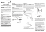
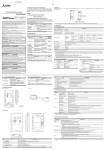
1
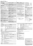
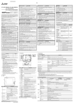
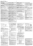
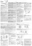
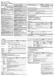
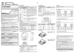
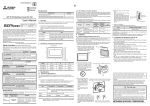
JY997D32901K Side B Side JAPANESE Side ENGLISH A B GT1045-QSBD, GT1040-QBBD GT10 General Description Manual Number JY997D32901K Date April 2015 This manual describes the specifications of the product. Before use, read this manual and manuals of relevant products fully to acquire proficiency in handling and operating the product. Make sure to learn all the product information, safety information, and precautions. And, store this manual in a safe place so that you can take it out and read it whenever necessary. Always forward it to the end user. Registration The company name and the product name to be described in this manual are the registered trademarks or trademarks of each company. Effective April 2015 Specifications are subject to change without notice. 2008 MITSUBISHI ELECTRIC CORPORATION Safety Precaution (Read these precautions before using.) Before using this product, please read this manual and the relevant manuals introduced in this manual carefully and pay full attention to safety to handle the product correctly. The precautions given in this manual are concerned with this product. In this manual, the safety precautions are ranked as "WARNING" and "CAUTION". Indicates that incorrect handling may cause hazardous conditions, resulting in death or severe injury. Indicates that incorrect handling may cause hazardous conditions, resulting in medium or slight personal injury or physical damage. Depending on circumstances, procedures indicated by "CAUTION" may also be linked to serious results. In any case, it is important to follow the directions for usage. STARTUP/MAINTENANCE PRECAUTIONS Be sure to shut off all phases of the external power supply used by the system before mounting or removing the GOT to/from the panel. Not doing so can cause the unit to fail or malfunction. When installing the battery wear an earth band etc. to avoid the static electricity. The static electricity can cause the unit to fail or malfunction. Before starting cleaning or terminal screw retightening, always switch off the power externally in all phases. Not switching the power off in all phases can cause a unit failure or malfunction. Undertightening can cause a short circuit or malfunction. Overtightening can cause a short circuit or malfunction due to the damage of the screws or unit. MOUNTING PRECAUTIONS STARTUP/MAINTENANCE PRECAUTIONS Use the GOT in the environment that satisfies the general specifications described in this manual. Not doing so can cause an electric shock, fire, malfunction or product damage or deterioration. Do not connect directly to line voltage. Line voltage must be supplied by a suitable, approved isolating transformer having short circuit capacity not exceeding 100VA maximum, 26.2VDC max. Ne pas connecter directement à la tension de la ligne. La tension de la ligne doit être fournie par un transformateur d'isolement approprié et approuvé ayant une capacité de court-circuit ne dépassant pas 100 VA maximum, 26.2VDC max. When mounting the GOT to the control panel, tighten the mounting screws in the specified torque range. Undertightening can cause the GOT to drop, short circuit or malfunction, and deteriorate the waterproof effect and oilproof effect Overtightening can cause a drop, short circuit or malfunction due to the damage of the screws or the GOT, and deteriorate the waterproof effect and oilproof effect due to distortion of the protective cover for oil, GOT or panel. When using the GOT in the environment of oil or chemicals, use the protective cover for oil. Failure to do so may cause failure or malfunction due to the oil or chemical entering into the GOT. Be sure to shut off all phases of the external power supply used by the system before wiring. Failure to do so may result in an electric shock, product damage or malfunctions. Use 60 to 75ºC, 16AWG (1.3mm2) maximum copper conductors only. Torque from 0.22 N•m to 0.25 N•m Please make sure to ground FG terminal of the GOT power supply section by applying 100 or less which is used exclusively for the GOT. Not doing so may cause an electric shock or malfunction. Correctly wire the GOT power supply section after confirming the rated voltage and terminal arrangement of the product. Not doing so can cause a fire or failure. Tighten the terminal screws of the GOT power supply section in the specified torque range. Undertightening can cause a short circuit or malfunction. Overtightening can cause a short circuit or malfunction due to the damage of the screws or the GOT. Exercise care to avoid foreign matter such as chips and wire offcuts entering the GOT. Not doing so can cause a fire, failure or malfunction. WIRING PRECAUTIONS DESIGN PRECAUTIONS Do not bundle the control and communication cables with main-circuit, power or other wiring. Run the above cables separately from such wiring and keep them a minimum of 100mm (3.94in.) apart.Not doing so noise can cause a malfunction. Do not press the GOT display section with a pointed material as a pen or driver. Doing so can result in a damage or failure of the display section. Before connecting to GOT, turn ON the controller to enable the communication. When the communication of controller is not available, a communication error may occur in GOT. Bundled Items Remark GT1045-QSBD GT1040-QBBD Plug the communication cable into the connector of the connected unit and tighten the mounting and terminal screws in the specified torque range. Undertightening can cause a short circuit or malfunction. Overtightening can cause a short circuit or malfunction due to the damage of the screws or unit. TEST OPERATION PRECAUTIONS Before performing the test operations of the user creation monitor screen (such as turning ON or OFF bit device, changing the word device current value, changing the settings or current values of the timer or counter), read through the manual carefully and make yourself familiar with the operation method. During test operation, never change the data of the devices which are used to perform significant operation for the system. False output or malfunction can cause an accident. GT1045-QSBD and GT1040-QBBD When power is on, do not touch the terminals. Doing so can cause an electric shock or malfunction. Connect the battery correctly. Do not discharge, disassemble, heat, short, solder or throw the battery into the fire. Incorrect handling may cause the battery to generate heat, burst or take fire, resulting in injuries or fires. Replace GT11-50BAT with CR2450HR by Hitachi Maxell only. Use of another battery may present a risk of fire or explosion. See owner's manual for safety instructions. Remplacez GT11-50BAT avec CR2450HR par Hitachi Maxell uniquement. L’utilisation d’une autre batterie peut entraîner un risque d’incendie ou d’explosion. Se reporter au manuel du propriétaire pour connaître les consignes de sécurité. Warning, battery may explode if mistreated. Do not recharge, disassemble or dispose of in fire. Avertissement, la batterie risque d'exploser si elle n’est pas manipulée correctement. Ne pas la recharger, la démonter ni la jeter au feu. **** Power type D:24VDC Panel color type B:Black Maintenance Supplies Display device type S:STN color B:STN monochrome(blue/white) Quantity 4 This note does not guarantee that an entire mechanical module produced in accordance with the contents of this note will comply with the following standards. Compliance to EMC directive for the entire mechanical module should be checked by the user / manufacturer. For more details please contact the local Mitsubishi Electric sales site. Attention This product is designed for use in industrial applications. Authorized Representative in the European Community: Mitsubishi Electric Europe B.V. Gothaer Str. 8, 40880 Ratingen, Germany The following products have shown compliance through direct testing (to the identified standards) and design analysis (forming a technical construction file) to the European Directive for Electromagnetic Compatibility (2004/108/EC) when used as directed by the appropriate documentation. Type :Programmable Controller (Open Type Equipment) Standard Remark EMI Compliance with all relevant aspects of the standard. (Radiated Emissions) EMS Compliance with all relevant aspects of the standard. (ESD, RF electromagnetic field, EFTB, Surge, RF conducted disturbances and Power frequency magnetic field) For more details please contact the local Mitsubishi Electric sales site. Manual Number (Model Code) GT10 User's Manual (sold separately) Describes the GT10 hardwarerelevant content such as part names, external dimensions, mounting, power supply wiring, specifications, and introduction to option devices JY997D24701 (09R819) GOT1000 Series Connection Manual 1/3, 2/3, 3/3 (sold separately) *1 Describes system configurations of the connection method applicable to SH-080532ENG GOT1000 series and cable creation (1D7M26) method GT Designer2 Version2 Basic Operation/Data Transfer Manual (For GOT1000 Series) (sold separately) *1 Describes methods of the GT Designer2 installation operation, basic SH-080529ENG operation for drawing and transmitting (1D7M24) data to GOT1000 series GT Designer2 Version2 Screen Design Manual (For GOT1000 Series) 1/3, 2/3, 3/3 (sold separately) *1 Describes specifications and settings SH-080530ENG of the object functions used in GT (1D7M25) Designer2 GT Designer3 Version1 Screen Design Manual (For GOT1000 Series) (Fundamentals) 1/2, 2/2 (sold separately) *1 Describes methods of the GT Designer3 installation operation, basic SH-080866ENG operation for drawing and transmitting (1D7MB9) data to GOT1000 series GT Designer3 Version1 Screen Design Manual (For GOT1000 Series) (Functions) 1/2, 2/2 (sold separately) *1 Describes specifications and settings SH-080867ENG of the object functions used in GT (1D7MC1) Designer3 *1 Stored in the GT Works 2/GT Designer2/GT Works3/GT Designer3 in PDF format. For details of a PLC to be connected, refer to the PLC user's manual respectively. Specifications GT1045-QSBD C drive*2 GT1040-QBBD Flash memory ROM (Internal), for storing project data (3M bytes or less) and OS Life (Number of write times) 100,000 times D drive SRAM (Internal), for storing alarm history, recipe data and time action setting value Battery GT11-50BAT lithium battery 1 Resolution Q:320 × 240(QVGA) Type Magnesium maganese dioxide lithium primary battery 1 Display color type 5:256 colors supported 0:Monochrome(black/white) 5:5.7" 4:4.7" 3:4.5" 2:3.7" GT10 Backup target Clock data, alarm history and recipe data Life Approx. 5 years (Operating ambient temperature of 25) 1. Specifications Buzzer output (a buzzer that sounds Single tone (LONG/ SHORT/ OFF adjustable) when touch keys are pressed) Environmental protective structure*3 Equivalent to IP67 (JEM1030) (front section) External dimensions W139(5.47) H112(4.4) D41(1.61)[mm](inch) (Excluding mounting fixtures) (Horizontal format) 1.1 General Specifications Specifications Item Operating ambient temperature 0 to 50C Other than display section 0 to 55C (When mounted horizontally), 0 to 50C (When mounted vertically) Storage ambient temperature -20 to 60C Operating ambient humidity 10 to 90% RH, non-condensing (The wet bulb temperature is 39C or less.) Storage ambient humidity 10 to 90% RH, non-condensing (The wet bulb temperature is 39C or less.) Vibration resistance Conforms to JIS B3502 and IEC61131-2 Under intermittent vibration Under continuous vibration Built-in interface Frequency Acceleration Half-amplitude 5 to 9Hz -- 3.5mm 9 to 150Hz 9.8m/s2 -- 5 to 9Hz -- 1.75mm 9 to 150Hz 4.9m/s2 -- 10 times each in X, Y and Z directions Conforms to JIS B3502, IEC 61131-2 (147m/s2, 11 ms, Sine half-wave pulse, 3 times each in the X, Y, and Z directions.) Operating atmosphere Must be free of lamp black, corrosive gas, flammable gas, or excessive amount of electroconductive dust particles and must be no direct sunlight. (Same as for saving) Operating altitude*1 2000 m (6562 ft) max. Installation location Inside control panel Overvoltage category*2 II or less Pollution degree*3 2 or less Cooling method Self-cooling Grounding Class D grounding (100 or less). To be connected to the panel when grounding is not possible *1 Do not use or store the GOT under pressure higher than the atmospheric pressure of altitude 0m (0ft.). Failure to observe this instruction may cause a malfunction. When the air inside the control panel is purged by pressurization, the surface sheet may be lifted by high pressure. As a result, the touch panel may be difficult to press, and the sheet may be peeled off. *2 This indicates the section of the power supply to which the equipment is assumed to be connected between the public electrical power distribution network and the machinery within the premises. Category II applies to equipment for which electrical power is supplied from fixed facilities. The surge voltage withstand level for up to the raged voltage of 300 V is 2500 V. *3 This index indicates the degree to which conductive material is generated in the environment where the equipment is used. In pollution degree 2, only non-conductive pollution occurs but temporary conductivity may be produced due to condensation. 1.2 Performance Specifications RS-232 RS-232 1ch Transmission speed : 115,200/57,600/38,400/19,200/9,600/4,800bps Connector shape : D-sub 9-pin (Male) Application : PLC communication, bar code reader connection, PC communication (Project data upload/download, OS installation, transparent function) USB USB (Full Speed 12Mbps) 1ch Connector shape: Mini-B Application: PC communication (Project data upload/download, OS installation, transparent function) GT10-50FMB For connecting GT10-50FMB memory board Panel cutting dimensions W130 (5.11”) H103(4.05”) [mm] (inch) (Horizontal format) Weight 0.45kg (Excluding mounting fixtures) Compatible software package GT Designer2 Version 2.90U or later/GT Designer3 Version 1.01B or later *1 • Bright dots (always lit) and dark dots (unlit) may appear on a liquid crystal display panel. It is impossible to completely avoid this symptom, as the liquid crystal display comprises of a great number of display elements. Flickers may be observed depending on the display color. Please note that these dots appear due to its characteristic and are not caused by product defect. • Flickers and partial discoloration may be generated on the liquid crystal display panel due to the display contents or the contrast adjustment. However, please note that these phenomena appear due to its characteristic and are not caused by product defect. • There is a difference in the display brightness and the color tones between liquid crystal display panels. When using multiple liquid crystal display panels, please note that there is an individual difference between them. • A crosstalk (shadow as an extension of the display) may appear on the liquid crystal display panel. Please note that it appears due to its characteristic. • When the display section is seen from the outside of the display angle, the display color seems like it has changed. Please note that it is due to its characteristic. Please note that the response time, brightness and color of the liquid crystal display panel may vary depending on the usage environmental temperature. Especially in the low temperature environment, the display response becomes slow due to the characteristics of the STN liquid crystal. Please check the display response in advance for using this product. • When the same screen is displayed for a long time, an incidental color or partial discoloration is generated on the screen due to heat damage, and it may not disappear. To prevent heat damage, the screen saver function is effective. For details on the screen saver function, refer to the following. GT10 User's Manual *2 ROM in which new data can be written without deleting the written data. *3 Note that this does not guarantee all users' operation environment. In addition, the product may not be used in environments under exposition of oil or chemicals for a long period of time, or in environments filled with oil-mist. *4 Set the terminating resistor selector switch of the GOT in accordance with the connection type when adopting GOT multidrop connection. For details of GOT multidrop connection, refer to the following. GOT1000 Series Connection Manual 1.3 Power Supply Specifications Specifications Item GT1045-QSBD GT1040-QBBD Specifications Type STN color liquid crystal 4.7" Resolution 320 240 dots (Horizontal format) Input power supply voltage 24VDC (+10% -15%) Display size W96(3.77) H72(2.83) [mm](inch) (Horizontal format) Display character 16-dot standard font: 40 characters 15 lines, 12-dot standard font: 53 characters 20 lines (Horizontal format) Fuse (built-in, not exchangeable) Display color 256 colors STN monochrome (white/blue) liquid crystal (For details on power supply wiring, such as the allowable cable size and tightening torque, refer to the additional manual, "GT10 User's Manual".) Screen size Monochrome (white/blue), 16 scales Display angle Left/Right: 50 degrees, Top: 40 degrees, Bottom: 70 degrees Left/Right: 45 degrees, Top: 20 degrees, Bottom: 40 degrees (Horizontal format) (Horizontal format) Contrast adjustment 16-level adjustment Intensity of LCD only 150 [cd/m2] Life Approx. 50,000h. (Time for display intensity to become 1/5 at operating ambient temperature of 25C) Number of touch keys Maximum 50 keys/screen (Matrix resistive film touch panel) Key size Minimum 16 16 dots (per key) Backlight Touch panel RS-422/485 1ch Transmission speed : 115,200/57,600/38,400/19,200/9,600/4,800bps Connector shape : D-sub 9-pin (Female) Application : PLC communication Terminating resistor*4: Open/110/330 (Switched by terminating resistor selector switch) (At factory shipment: 330 Sweep Count Shock resistance Display section*1 RS-422/485 GT1045-QSBD/GT1040-QBBD Display section LED Backlight off/screen saving time can be set. Simultaneous pressing of two (or more) areas Enable (2-point press) Life Up to 75mm (2.95inch) Contents Manual name GT10 General Description (This manual) GOT1000 series GOT units F The following manuals are relevant to this product. When these loose manuals are required, please consult with our local distributor. Panel Mounting Packing Screen size type F 2) General notes on Power supply The G T1045-QS B D a nd GT10 40-QB BD uni t requires an additional ferrite filter to be attached to the 24V DC power supply cables. The filter should be attached in a similar manner as shown in the figure opposite, i.e. the power cables are wrapped ar oun d th e fi lt er. H ow ev er, as wi th a ll E MC situations the more correctly applied precautions the better the systems Electro-magnetic Compatibility. The ferrite recommended is a TDK ZCAT3035-1330 or similar. The ferrite should be placed as near to the 24V DC terminals of the GT1045-QSBD and GT1040-QBBD as possible (which should be within 75mm of the GOT terminal). Compliance with EC directive (CE Marking) Memory F Associated Manuals When transporting lithium batteries, make sure to treat them based on the transport regulations. (Refer to User's Manual for details of the regurated models.) Before transporting the GOT, turn the GOT power on and check that the battery voltage status is normal on the Time setting & display screen (utilities screen). In addition, confirm that the adequate battery life remains on the rating plate. Transporting the GOT with the low battery voltage or the battery the reached battery life may unstabilize the backup data unstable during transportation. Make sure to transport the GOT main unit and/or relevant unit(s) in the manner they will not be exposed to the impact exceeding the impact resistance described in the general specifications of this manual, as they are precision devices. Failure to do so may cause the unit to fail. Check if the unit operates correctly after transportation. Item GOT main unit (The maintenance supplies below are packed with the product.) GT01-C30R4-8P modified as shown in EX.1 140mm Comes equipped (5.51inch) Added by user Added by user When disposing of the product, handle it as industrial waste. When disposing of batteries, separate them from other wastes according to the local regulations. (For details of the battery directive in EU member states, refer GOT User's Manual.) EN61131-2 : 2007 Programmable controllers- Equipment, requirement and tests User Made Cables Those cables need to be independently tested by the user to demonstrate EMC compatibility when they are used with Mitsubishi GOT unit and FX3U Programmable Controllers. Programmable controller DISPOSAL PRECAUTIONS TRANSPORTATION PRECAUTIONS Existing Cables Ex.1 F = Ferrite core Ex. NEC TOKIN - ESD-R-17S, TDK - ZCAT3035-1330 or similar GT01-C30R4-8P 250mm 100mm (9.84inch) (3.93inch) Requirement for Compliance with EMC directive STARTUP/MAINTENANCE PRECAUTIONS GT10 4 0 - Panel Mounting Bracket (with M4 20 screws) GOT Unit Do not disassemble or modify the unit. Doing so can cause a failure, malfunction, injury or fire. Do not touch the conductive and electronic parts of the unit directly. Doing so can cause a unit malfunction or failure. The cables connected to the unit must be run in ducts or clamped. Not doing so can cause the unit or cable to be damaged due to the dangling, motion or accidental pulling of the cables or can cause a malfunction due to a cable connection fault. When unplugging the cable connected to the unit, do not hold and pull the cable portion. Doing so can cause the unit or cable to be damaged or can cause a malfunction due to a cable connection fault. Do not drop or apply any impact to the battery. If any impact has been applied, discard the battery and never use it. The battery may be damaged by the drop or impact. Before touching the unit, always touch grounded metal, etc. to discharge static electricity from human body, etc. Not doing so can cause the unit to fail malfunction. Replace battery with GT11-50BAT by Mitsubishi electric Co. only. Use of another battery may present a risk of fire or explosion. Dispose of used battery promptly. Keep away from children. Do not disassemble and do not dispose of in fire. Explanation of the GOT model name Model Name 1) General notes on the use of communication cables Any device which utilizes a data communication function is susceptible to the wider effects of local EMC noise. Therefore, when installing any communication cables care should always be taken with the routing and location of those cables. The GOT units identified on the previous chapter are compliant with the EMC requirement when the following communication cables are used. WIRING PRECAUTIONS DESIGN PRECAUTIONS Some failures of the GOT or cable may keep the outputs on or off. An external monitoring circuit should be provided to check for output signals which may lead to a serious accident. Not doing so can cause an accident due to false output or malfunction. If a communication fault (including cable disconnection) occurs during monitoring on the GOT, communication between the GOT and PLC CPU is suspended and the GOT becomes inoperative. A system where the GOT is used should be configured to perform any significant operation to the system by using the switches of a device other than the GOT on the assumption that a GOT communication fault will occur. Not doing so can cause an accident due to false output or malfunction. Do not use the GOT as the warning device that may cause a serious accident. An independent and redundant hardware or mechanical interlock is required to configure the device that displays and outputs serious warning. Failure to observe this instruction may result in an accident due to incorrect output or malfunction. Incorrect operation of the touch switch(s) may lead to a serious accident if the GOT backlight is gone out. When the GOT backlight goes out, causes the monitor screen to appear blank, while the input of the touch switch(s) remains active. This may confuse an operator in thinking that the GOT is in "screensaver" mode, who then tries to release the GOT from this mode by touching the display section, which may cause a touch switch to operate. Notes for compliance to EMC regulation MOUNTING PRECAUTIONS 1 million times or more (operating force 0.98N max.) 300 [cd/m2] Item GT1045-QSBD GT1040-QBBD 1.0A Power consumption, (At backlight off) 3.6W (150mA/24VDC) or less, (2.9W (120mA/24VDC) or less) Inrush current 15A or less (26.4VDC) 2ms Permissible instantaneous power failure time*1 Within 5ms Noise immunity Noise voltage: 1000Vp-p, Noise width: 1s (by noise simulator of 30 to 100Hz noise frequency) Dielectric withstand voltage 500VAC for 1 minute (across power supply terminals and earth) Insulation resistance 10M or larger by insulation resistance tester (across power supply terminals and earth) *1 The GOT continues to operate even upon 5ms or shorter instantaneous power failure. The GOT stops operating if there is extended power failure or voltage drop, while it automatically resumes operation as soon as the power is restored. This manual confers no industrial property rights or any rights of any other kind, nor does it confer any patent licenses. Mitsubishi Electric Corporation cannot be held responsible for any problems involving industrial property rights which may occur as a result of using the contents noted in this manual. Warranty Mitsubishi will not be held liable for damage caused by factors found not to be the cause of Mitsubishi; opportunity loss or lost profits caused by faults in the Mitsubishi products; damage, secondary damage, accident compensation caused by special factors unpredictable by Mitsubishi; damages to products other than Mitsubishi products; and to other duties. For safe use This product has been manufactured as a general-purpose part for general industries, and has not been designed or manufactured to be incorporated in a device or system used in purposes related to human life. Before using the product for special purposes such as nuclear power, electric power, aerospace, medicine or passenger movement vehicles, consult with Mitsubishi Electric. This product has been manufactured under strict quality control. However when installing the product where major accidents or losses could occur if the product fails, install appropriate backup or failsafe functions in the system. HEAD OFFICE : TOKYO BUILDING, 2-7-3 MARUNOUCHI, CHIYODA-KU, TOKYO 100-8310, JAPAN JY997D32901K Side B Side JAPANESE Side ENGLISH A B GT1045-QSBD, GT1040-QBBD GT10 General Description Manual Number JY997D32901K Date April 2015 This manual describes the specifications of the product. Before use, read this manual and manuals of relevant products fully to acquire proficiency in handling and operating the product. Make sure to learn all the product information, safety information, and precautions. And, store this manual in a safe place so that you can take it out and read it whenever necessary. Always forward it to the end user. Registration The company name and the product name to be described in this manual are the registered trademarks or trademarks of each company. Effective April 2015 Specifications are subject to change without notice. 2008 MITSUBISHI ELECTRIC CORPORATION Safety Precaution (Read these precautions before using.) Before using this product, please read this manual and the relevant manuals introduced in this manual carefully and pay full attention to safety to handle the product correctly. The precautions given in this manual are concerned with this product. In this manual, the safety precautions are ranked as "WARNING" and "CAUTION". Indicates that incorrect handling may cause hazardous conditions, resulting in death or severe injury. Indicates that incorrect handling may cause hazardous conditions, resulting in medium or slight personal injury or physical damage. Depending on circumstances, procedures indicated by "CAUTION" may also be linked to serious results. In any case, it is important to follow the directions for usage. STARTUP/MAINTENANCE PRECAUTIONS Be sure to shut off all phases of the external power supply used by the system before mounting or removing the GOT to/from the panel. Not doing so can cause the unit to fail or malfunction. When installing the battery wear an earth band etc. to avoid the static electricity. The static electricity can cause the unit to fail or malfunction. Before starting cleaning or terminal screw retightening, always switch off the power externally in all phases. Not switching the power off in all phases can cause a unit failure or malfunction. Undertightening can cause a short circuit or malfunction. Overtightening can cause a short circuit or malfunction due to the damage of the screws or unit. MOUNTING PRECAUTIONS STARTUP/MAINTENANCE PRECAUTIONS Use the GOT in the environment that satisfies the general specifications described in this manual. Not doing so can cause an electric shock, fire, malfunction or product damage or deterioration. Do not connect directly to line voltage. Line voltage must be supplied by a suitable, approved isolating transformer having short circuit capacity not exceeding 100VA maximum, 26.2VDC max. Ne pas connecter directement à la tension de la ligne. La tension de la ligne doit être fournie par un transformateur d'isolement approprié et approuvé ayant une capacité de court-circuit ne dépassant pas 100 VA maximum, 26.2VDC max. When mounting the GOT to the control panel, tighten the mounting screws in the specified torque range. Undertightening can cause the GOT to drop, short circuit or malfunction, and deteriorate the waterproof effect and oilproof effect Overtightening can cause a drop, short circuit or malfunction due to the damage of the screws or the GOT, and deteriorate the waterproof effect and oilproof effect due to distortion of the protective cover for oil, GOT or panel. When using the GOT in the environment of oil or chemicals, use the protective cover for oil. Failure to do so may cause failure or malfunction due to the oil or chemical entering into the GOT. Be sure to shut off all phases of the external power supply used by the system before wiring. Failure to do so may result in an electric shock, product damage or malfunctions. Use 60 to 75ºC, 16AWG (1.3mm2) maximum copper conductors only. Torque from 0.22 N•m to 0.25 N•m Please make sure to ground FG terminal of the GOT power supply section by applying 100 or less which is used exclusively for the GOT. Not doing so may cause an electric shock or malfunction. Correctly wire the GOT power supply section after confirming the rated voltage and terminal arrangement of the product. Not doing so can cause a fire or failure. Tighten the terminal screws of the GOT power supply section in the specified torque range. Undertightening can cause a short circuit or malfunction. Overtightening can cause a short circuit or malfunction due to the damage of the screws or the GOT. Exercise care to avoid foreign matter such as chips and wire offcuts entering the GOT. Not doing so can cause a fire, failure or malfunction. WIRING PRECAUTIONS DESIGN PRECAUTIONS Do not bundle the control and communication cables with main-circuit, power or other wiring. Run the above cables separately from such wiring and keep them a minimum of 100mm (3.94in.) apart.Not doing so noise can cause a malfunction. Do not press the GOT display section with a pointed material as a pen or driver. Doing so can result in a damage or failure of the display section. Before connecting to GOT, turn ON the controller to enable the communication. When the communication of controller is not available, a communication error may occur in GOT. Bundled Items Remark GT1045-QSBD GT1040-QBBD Plug the communication cable into the connector of the connected unit and tighten the mounting and terminal screws in the specified torque range. Undertightening can cause a short circuit or malfunction. Overtightening can cause a short circuit or malfunction due to the damage of the screws or unit. TEST OPERATION PRECAUTIONS Before performing the test operations of the user creation monitor screen (such as turning ON or OFF bit device, changing the word device current value, changing the settings or current values of the timer or counter), read through the manual carefully and make yourself familiar with the operation method. During test operation, never change the data of the devices which are used to perform significant operation for the system. False output or malfunction can cause an accident. GT1045-QSBD and GT1040-QBBD When power is on, do not touch the terminals. Doing so can cause an electric shock or malfunction. Connect the battery correctly. Do not discharge, disassemble, heat, short, solder or throw the battery into the fire. Incorrect handling may cause the battery to generate heat, burst or take fire, resulting in injuries or fires. Replace GT11-50BAT with CR2450HR by Hitachi Maxell only. Use of another battery may present a risk of fire or explosion. See owner's manual for safety instructions. Remplacez GT11-50BAT avec CR2450HR par Hitachi Maxell uniquement. L’utilisation d’une autre batterie peut entraîner un risque d’incendie ou d’explosion. Se reporter au manuel du propriétaire pour connaître les consignes de sécurité. Warning, battery may explode if mistreated. Do not recharge, disassemble or dispose of in fire. Avertissement, la batterie risque d'exploser si elle n’est pas manipulée correctement. Ne pas la recharger, la démonter ni la jeter au feu. **** Power type D:24VDC Panel color type B:Black Maintenance Supplies Display device type S:STN color B:STN monochrome(blue/white) Quantity 4 This note does not guarantee that an entire mechanical module produced in accordance with the contents of this note will comply with the following standards. Compliance to EMC directive for the entire mechanical module should be checked by the user / manufacturer. For more details please contact the local Mitsubishi Electric sales site. Attention This product is designed for use in industrial applications. Authorized Representative in the European Community: Mitsubishi Electric Europe B.V. Gothaer Str. 8, 40880 Ratingen, Germany The following products have shown compliance through direct testing (to the identified standards) and design analysis (forming a technical construction file) to the European Directive for Electromagnetic Compatibility (2004/108/EC) when used as directed by the appropriate documentation. Type :Programmable Controller (Open Type Equipment) Standard Remark EMI Compliance with all relevant aspects of the standard. (Radiated Emissions) EMS Compliance with all relevant aspects of the standard. (ESD, RF electromagnetic field, EFTB, Surge, RF conducted disturbances and Power frequency magnetic field) For more details please contact the local Mitsubishi Electric sales site. Manual Number (Model Code) GT10 User's Manual (sold separately) Describes the GT10 hardwarerelevant content such as part names, external dimensions, mounting, power supply wiring, specifications, and introduction to option devices JY997D24701 (09R819) GOT1000 Series Connection Manual 1/3, 2/3, 3/3 (sold separately) *1 Describes system configurations of the connection method applicable to SH-080532ENG GOT1000 series and cable creation (1D7M26) method GT Designer2 Version2 Basic Operation/Data Transfer Manual (For GOT1000 Series) (sold separately) *1 Describes methods of the GT Designer2 installation operation, basic SH-080529ENG operation for drawing and transmitting (1D7M24) data to GOT1000 series GT Designer2 Version2 Screen Design Manual (For GOT1000 Series) 1/3, 2/3, 3/3 (sold separately) *1 Describes specifications and settings SH-080530ENG of the object functions used in GT (1D7M25) Designer2 GT Designer3 Version1 Screen Design Manual (For GOT1000 Series) (Fundamentals) 1/2, 2/2 (sold separately) *1 Describes methods of the GT Designer3 installation operation, basic SH-080866ENG operation for drawing and transmitting (1D7MB9) data to GOT1000 series GT Designer3 Version1 Screen Design Manual (For GOT1000 Series) (Functions) 1/2, 2/2 (sold separately) *1 Describes specifications and settings SH-080867ENG of the object functions used in GT (1D7MC1) Designer3 *1 Stored in the GT Works 2/GT Designer2/GT Works3/GT Designer3 in PDF format. For details of a PLC to be connected, refer to the PLC user's manual respectively. Specifications GT1045-QSBD C drive*2 GT1040-QBBD Flash memory ROM (Internal), for storing project data (3M bytes or less) and OS Life (Number of write times) 100,000 times D drive SRAM (Internal), for storing alarm history, recipe data and time action setting value Battery GT11-50BAT lithium battery 1 Resolution Q:320 × 240(QVGA) Type Magnesium maganese dioxide lithium primary battery 1 Display color type 5:256 colors supported 0:Monochrome(black/white) 5:5.7" 4:4.7" 3:4.5" 2:3.7" GT10 Backup target Clock data, alarm history and recipe data Life Approx. 5 years (Operating ambient temperature of 25) 1. Specifications Buzzer output (a buzzer that sounds Single tone (LONG/ SHORT/ OFF adjustable) when touch keys are pressed) Environmental protective structure*3 Equivalent to IP67 (JEM1030) (front section) External dimensions W139(5.47) H112(4.4) D41(1.61)[mm](inch) (Excluding mounting fixtures) (Horizontal format) 1.1 General Specifications Specifications Item Operating ambient temperature 0 to 50C Other than display section 0 to 55C (When mounted horizontally), 0 to 50C (When mounted vertically) Storage ambient temperature -20 to 60C Operating ambient humidity 10 to 90% RH, non-condensing (The wet bulb temperature is 39C or less.) Storage ambient humidity 10 to 90% RH, non-condensing (The wet bulb temperature is 39C or less.) Vibration resistance Conforms to JIS B3502 and IEC61131-2 Under intermittent vibration Under continuous vibration Built-in interface Frequency Acceleration Half-amplitude 5 to 9Hz -- 3.5mm 9 to 150Hz 9.8m/s2 -- 5 to 9Hz -- 1.75mm 9 to 150Hz 4.9m/s2 -- 10 times each in X, Y and Z directions Conforms to JIS B3502, IEC 61131-2 (147m/s2, 11 ms, Sine half-wave pulse, 3 times each in the X, Y, and Z directions.) Operating atmosphere Must be free of lamp black, corrosive gas, flammable gas, or excessive amount of electroconductive dust particles and must be no direct sunlight. (Same as for saving) Operating altitude*1 2000 m (6562 ft) max. Installation location Inside control panel Overvoltage category*2 II or less Pollution degree*3 2 or less Cooling method Self-cooling Grounding Class D grounding (100 or less). To be connected to the panel when grounding is not possible *1 Do not use or store the GOT under pressure higher than the atmospheric pressure of altitude 0m (0ft.). Failure to observe this instruction may cause a malfunction. When the air inside the control panel is purged by pressurization, the surface sheet may be lifted by high pressure. As a result, the touch panel may be difficult to press, and the sheet may be peeled off. *2 This indicates the section of the power supply to which the equipment is assumed to be connected between the public electrical power distribution network and the machinery within the premises. Category II applies to equipment for which electrical power is supplied from fixed facilities. The surge voltage withstand level for up to the raged voltage of 300 V is 2500 V. *3 This index indicates the degree to which conductive material is generated in the environment where the equipment is used. In pollution degree 2, only non-conductive pollution occurs but temporary conductivity may be produced due to condensation. 1.2 Performance Specifications RS-232 RS-232 1ch Transmission speed : 115,200/57,600/38,400/19,200/9,600/4,800bps Connector shape : D-sub 9-pin (Male) Application : PLC communication, bar code reader connection, PC communication (Project data upload/download, OS installation, transparent function) USB USB (Full Speed 12Mbps) 1ch Connector shape: Mini-B Application: PC communication (Project data upload/download, OS installation, transparent function) GT10-50FMB For connecting GT10-50FMB memory board Panel cutting dimensions W130 (5.11”) H103(4.05”) [mm] (inch) (Horizontal format) Weight 0.45kg (Excluding mounting fixtures) Compatible software package GT Designer2 Version 2.90U or later/GT Designer3 Version 1.01B or later *1 • Bright dots (always lit) and dark dots (unlit) may appear on a liquid crystal display panel. It is impossible to completely avoid this symptom, as the liquid crystal display comprises of a great number of display elements. Flickers may be observed depending on the display color. Please note that these dots appear due to its characteristic and are not caused by product defect. • Flickers and partial discoloration may be generated on the liquid crystal display panel due to the display contents or the contrast adjustment. However, please note that these phenomena appear due to its characteristic and are not caused by product defect. • There is a difference in the display brightness and the color tones between liquid crystal display panels. When using multiple liquid crystal display panels, please note that there is an individual difference between them. • A crosstalk (shadow as an extension of the display) may appear on the liquid crystal display panel. Please note that it appears due to its characteristic. • When the display section is seen from the outside of the display angle, the display color seems like it has changed. Please note that it is due to its characteristic. Please note that the response time, brightness and color of the liquid crystal display panel may vary depending on the usage environmental temperature. Especially in the low temperature environment, the display response becomes slow due to the characteristics of the STN liquid crystal. Please check the display response in advance for using this product. • When the same screen is displayed for a long time, an incidental color or partial discoloration is generated on the screen due to heat damage, and it may not disappear. To prevent heat damage, the screen saver function is effective. For details on the screen saver function, refer to the following. GT10 User's Manual *2 ROM in which new data can be written without deleting the written data. *3 Note that this does not guarantee all users' operation environment. In addition, the product may not be used in environments under exposition of oil or chemicals for a long period of time, or in environments filled with oil-mist. *4 Set the terminating resistor selector switch of the GOT in accordance with the connection type when adopting GOT multidrop connection. For details of GOT multidrop connection, refer to the following. GOT1000 Series Connection Manual 1.3 Power Supply Specifications Specifications Item GT1045-QSBD GT1040-QBBD Specifications Type STN color liquid crystal 4.7" Resolution 320 240 dots (Horizontal format) Input power supply voltage 24VDC (+10% -15%) Display size W96(3.77) H72(2.83) [mm](inch) (Horizontal format) Display character 16-dot standard font: 40 characters 15 lines, 12-dot standard font: 53 characters 20 lines (Horizontal format) Fuse (built-in, not exchangeable) Display color 256 colors STN monochrome (white/blue) liquid crystal (For details on power supply wiring, such as the allowable cable size and tightening torque, refer to the additional manual, "GT10 User's Manual".) Screen size Monochrome (white/blue), 16 scales Display angle Left/Right: 50 degrees, Top: 40 degrees, Bottom: 70 degrees Left/Right: 45 degrees, Top: 20 degrees, Bottom: 40 degrees (Horizontal format) (Horizontal format) Contrast adjustment 16-level adjustment Intensity of LCD only 150 [cd/m2] Life Approx. 50,000h. (Time for display intensity to become 1/5 at operating ambient temperature of 25C) Number of touch keys Maximum 50 keys/screen (Matrix resistive film touch panel) Key size Minimum 16 16 dots (per key) Backlight Touch panel RS-422/485 1ch Transmission speed : 115,200/57,600/38,400/19,200/9,600/4,800bps Connector shape : D-sub 9-pin (Female) Application : PLC communication Terminating resistor*4: Open/110/330 (Switched by terminating resistor selector switch) (At factory shipment: 330 Sweep Count Shock resistance Display section*1 RS-422/485 GT1045-QSBD/GT1040-QBBD Display section LED Backlight off/screen saving time can be set. Simultaneous pressing of two (or more) areas Enable (2-point press) Life Up to 75mm (2.95inch) Contents Manual name GT10 General Description (This manual) GOT1000 series GOT units F The following manuals are relevant to this product. When these loose manuals are required, please consult with our local distributor. Panel Mounting Packing Screen size type F 2) General notes on Power supply The G T1045-QS B D a nd GT10 40-QB BD uni t requires an additional ferrite filter to be attached to the 24V DC power supply cables. The filter should be attached in a similar manner as shown in the figure opposite, i.e. the power cables are wrapped ar oun d th e fi lt er. H ow ev er, as wi th a ll E MC situations the more correctly applied precautions the better the systems Electro-magnetic Compatibility. The ferrite recommended is a TDK ZCAT3035-1330 or similar. The ferrite should be placed as near to the 24V DC terminals of the GT1045-QSBD and GT1040-QBBD as possible (which should be within 75mm of the GOT terminal). Compliance with EC directive (CE Marking) Memory F Associated Manuals When transporting lithium batteries, make sure to treat them based on the transport regulations. (Refer to User's Manual for details of the regurated models.) Before transporting the GOT, turn the GOT power on and check that the battery voltage status is normal on the Time setting & display screen (utilities screen). In addition, confirm that the adequate battery life remains on the rating plate. Transporting the GOT with the low battery voltage or the battery the reached battery life may unstabilize the backup data unstable during transportation. Make sure to transport the GOT main unit and/or relevant unit(s) in the manner they will not be exposed to the impact exceeding the impact resistance described in the general specifications of this manual, as they are precision devices. Failure to do so may cause the unit to fail. Check if the unit operates correctly after transportation. Item GOT main unit (The maintenance supplies below are packed with the product.) GT01-C30R4-8P modified as shown in EX.1 140mm Comes equipped (5.51inch) Added by user Added by user When disposing of the product, handle it as industrial waste. When disposing of batteries, separate them from other wastes according to the local regulations. (For details of the battery directive in EU member states, refer GOT User's Manual.) EN61131-2 : 2007 Programmable controllers- Equipment, requirement and tests User Made Cables Those cables need to be independently tested by the user to demonstrate EMC compatibility when they are used with Mitsubishi GOT unit and FX3U Programmable Controllers. Programmable controller DISPOSAL PRECAUTIONS TRANSPORTATION PRECAUTIONS Existing Cables Ex.1 F = Ferrite core Ex. NEC TOKIN - ESD-R-17S, TDK - ZCAT3035-1330 or similar GT01-C30R4-8P 250mm 100mm (9.84inch) (3.93inch) Requirement for Compliance with EMC directive STARTUP/MAINTENANCE PRECAUTIONS GT10 4 0 - Panel Mounting Bracket (with M4 20 screws) GOT Unit Do not disassemble or modify the unit. Doing so can cause a failure, malfunction, injury or fire. Do not touch the conductive and electronic parts of the unit directly. Doing so can cause a unit malfunction or failure. The cables connected to the unit must be run in ducts or clamped. Not doing so can cause the unit or cable to be damaged due to the dangling, motion or accidental pulling of the cables or can cause a malfunction due to a cable connection fault. When unplugging the cable connected to the unit, do not hold and pull the cable portion. Doing so can cause the unit or cable to be damaged or can cause a malfunction due to a cable connection fault. Do not drop or apply any impact to the battery. If any impact has been applied, discard the battery and never use it. The battery may be damaged by the drop or impact. Before touching the unit, always touch grounded metal, etc. to discharge static electricity from human body, etc. Not doing so can cause the unit to fail malfunction. Replace battery with GT11-50BAT by Mitsubishi electric Co. only. Use of another battery may present a risk of fire or explosion. Dispose of used battery promptly. Keep away from children. Do not disassemble and do not dispose of in fire. Explanation of the GOT model name Model Name 1) General notes on the use of communication cables Any device which utilizes a data communication function is susceptible to the wider effects of local EMC noise. Therefore, when installing any communication cables care should always be taken with the routing and location of those cables. The GOT units identified on the previous chapter are compliant with the EMC requirement when the following communication cables are used. WIRING PRECAUTIONS DESIGN PRECAUTIONS Some failures of the GOT or cable may keep the outputs on or off. An external monitoring circuit should be provided to check for output signals which may lead to a serious accident. Not doing so can cause an accident due to false output or malfunction. If a communication fault (including cable disconnection) occurs during monitoring on the GOT, communication between the GOT and PLC CPU is suspended and the GOT becomes inoperative. A system where the GOT is used should be configured to perform any significant operation to the system by using the switches of a device other than the GOT on the assumption that a GOT communication fault will occur. Not doing so can cause an accident due to false output or malfunction. Do not use the GOT as the warning device that may cause a serious accident. An independent and redundant hardware or mechanical interlock is required to configure the device that displays and outputs serious warning. Failure to observe this instruction may result in an accident due to incorrect output or malfunction. Incorrect operation of the touch switch(s) may lead to a serious accident if the GOT backlight is gone out. When the GOT backlight goes out, causes the monitor screen to appear blank, while the input of the touch switch(s) remains active. This may confuse an operator in thinking that the GOT is in "screensaver" mode, who then tries to release the GOT from this mode by touching the display section, which may cause a touch switch to operate. Notes for compliance to EMC regulation MOUNTING PRECAUTIONS 1 million times or more (operating force 0.98N max.) 300 [cd/m2] Item GT1045-QSBD GT1040-QBBD 1.0A Power consumption, (At backlight off) 3.6W (150mA/24VDC) or less, (2.9W (120mA/24VDC) or less) Inrush current 15A or less (26.4VDC) 2ms Permissible instantaneous power failure time*1 Within 5ms Noise immunity Noise voltage: 1000Vp-p, Noise width: 1s (by noise simulator of 30 to 100Hz noise frequency) Dielectric withstand voltage 500VAC for 1 minute (across power supply terminals and earth) Insulation resistance 10M or larger by insulation resistance tester (across power supply terminals and earth) *1 The GOT continues to operate even upon 5ms or shorter instantaneous power failure. The GOT stops operating if there is extended power failure or voltage drop, while it automatically resumes operation as soon as the power is restored. This manual confers no industrial property rights or any rights of any other kind, nor does it confer any patent licenses. Mitsubishi Electric Corporation cannot be held responsible for any problems involving industrial property rights which may occur as a result of using the contents noted in this manual. Warranty Mitsubishi will not be held liable for damage caused by factors found not to be the cause of Mitsubishi; opportunity loss or lost profits caused by faults in the Mitsubishi products; damage, secondary damage, accident compensation caused by special factors unpredictable by Mitsubishi; damages to products other than Mitsubishi products; and to other duties. For safe use This product has been manufactured as a general-purpose part for general industries, and has not been designed or manufactured to be incorporated in a device or system used in purposes related to human life. Before using the product for special purposes such as nuclear power, electric power, aerospace, medicine or passenger movement vehicles, consult with Mitsubishi Electric. This product has been manufactured under strict quality control. However when installing the product where major accidents or losses could occur if the product fails, install appropriate backup or failsafe functions in the system. HEAD OFFICE : TOKYO BUILDING, 2-7-3 MARUNOUCHI, CHIYODA-KU, TOKYO 100-8310, JAPAN JY997D32901K Side B Side JAPANESE Side ENGLISH A B GT1045-QSBD, GT1040-QBBD GT10 General Description Manual Number JY997D32901K Date April 2015 This manual describes the specifications of the product. Before use, read this manual and manuals of relevant products fully to acquire proficiency in handling and operating the product. Make sure to learn all the product information, safety information, and precautions. And, store this manual in a safe place so that you can take it out and read it whenever necessary. Always forward it to the end user. Registration The company name and the product name to be described in this manual are the registered trademarks or trademarks of each company. Effective April 2015 Specifications are subject to change without notice. 2008 MITSUBISHI ELECTRIC CORPORATION Safety Precaution (Read these precautions before using.) Before using this product, please read this manual and the relevant manuals introduced in this manual carefully and pay full attention to safety to handle the product correctly. The precautions given in this manual are concerned with this product. In this manual, the safety precautions are ranked as "WARNING" and "CAUTION". Indicates that incorrect handling may cause hazardous conditions, resulting in death or severe injury. Indicates that incorrect handling may cause hazardous conditions, resulting in medium or slight personal injury or physical damage. Depending on circumstances, procedures indicated by "CAUTION" may also be linked to serious results. In any case, it is important to follow the directions for usage. STARTUP/MAINTENANCE PRECAUTIONS Be sure to shut off all phases of the external power supply used by the system before mounting or removing the GOT to/from the panel. Not doing so can cause the unit to fail or malfunction. When installing the battery wear an earth band etc. to avoid the static electricity. The static electricity can cause the unit to fail or malfunction. Before starting cleaning or terminal screw retightening, always switch off the power externally in all phases. Not switching the power off in all phases can cause a unit failure or malfunction. Undertightening can cause a short circuit or malfunction. Overtightening can cause a short circuit or malfunction due to the damage of the screws or unit. MOUNTING PRECAUTIONS STARTUP/MAINTENANCE PRECAUTIONS Use the GOT in the environment that satisfies the general specifications described in this manual. Not doing so can cause an electric shock, fire, malfunction or product damage or deterioration. Do not connect directly to line voltage. Line voltage must be supplied by a suitable, approved isolating transformer having short circuit capacity not exceeding 100VA maximum, 26.2VDC max. Ne pas connecter directement à la tension de la ligne. La tension de la ligne doit être fournie par un transformateur d'isolement approprié et approuvé ayant une capacité de court-circuit ne dépassant pas 100 VA maximum, 26.2VDC max. When mounting the GOT to the control panel, tighten the mounting screws in the specified torque range. Undertightening can cause the GOT to drop, short circuit or malfunction, and deteriorate the waterproof effect and oilproof effect Overtightening can cause a drop, short circuit or malfunction due to the damage of the screws or the GOT, and deteriorate the waterproof effect and oilproof effect due to distortion of the protective cover for oil, GOT or panel. When using the GOT in the environment of oil or chemicals, use the protective cover for oil. Failure to do so may cause failure or malfunction due to the oil or chemical entering into the GOT. Be sure to shut off all phases of the external power supply used by the system before wiring. Failure to do so may result in an electric shock, product damage or malfunctions. Use 60 to 75ºC, 16AWG (1.3mm2) maximum copper conductors only. Torque from 0.22 N•m to 0.25 N•m Please make sure to ground FG terminal of the GOT power supply section by applying 100 or less which is used exclusively for the GOT. Not doing so may cause an electric shock or malfunction. Correctly wire the GOT power supply section after confirming the rated voltage and terminal arrangement of the product. Not doing so can cause a fire or failure. Tighten the terminal screws of the GOT power supply section in the specified torque range. Undertightening can cause a short circuit or malfunction. Overtightening can cause a short circuit or malfunction due to the damage of the screws or the GOT. Exercise care to avoid foreign matter such as chips and wire offcuts entering the GOT. Not doing so can cause a fire, failure or malfunction. WIRING PRECAUTIONS DESIGN PRECAUTIONS Do not bundle the control and communication cables with main-circuit, power or other wiring. Run the above cables separately from such wiring and keep them a minimum of 100mm (3.94in.) apart.Not doing so noise can cause a malfunction. Do not press the GOT display section with a pointed material as a pen or driver. Doing so can result in a damage or failure of the display section. Before connecting to GOT, turn ON the controller to enable the communication. When the communication of controller is not available, a communication error may occur in GOT. Bundled Items Remark GT1045-QSBD GT1040-QBBD Plug the communication cable into the connector of the connected unit and tighten the mounting and terminal screws in the specified torque range. Undertightening can cause a short circuit or malfunction. Overtightening can cause a short circuit or malfunction due to the damage of the screws or unit. TEST OPERATION PRECAUTIONS Before performing the test operations of the user creation monitor screen (such as turning ON or OFF bit device, changing the word device current value, changing the settings or current values of the timer or counter), read through the manual carefully and make yourself familiar with the operation method. During test operation, never change the data of the devices which are used to perform significant operation for the system. False output or malfunction can cause an accident. GT1045-QSBD and GT1040-QBBD When power is on, do not touch the terminals. Doing so can cause an electric shock or malfunction. Connect the battery correctly. Do not discharge, disassemble, heat, short, solder or throw the battery into the fire. Incorrect handling may cause the battery to generate heat, burst or take fire, resulting in injuries or fires. Replace GT11-50BAT with CR2450HR by Hitachi Maxell only. Use of another battery may present a risk of fire or explosion. See owner's manual for safety instructions. Remplacez GT11-50BAT avec CR2450HR par Hitachi Maxell uniquement. L’utilisation d’une autre batterie peut entraîner un risque d’incendie ou d’explosion. Se reporter au manuel du propriétaire pour connaître les consignes de sécurité. Warning, battery may explode if mistreated. Do not recharge, disassemble or dispose of in fire. Avertissement, la batterie risque d'exploser si elle n’est pas manipulée correctement. Ne pas la recharger, la démonter ni la jeter au feu. **** Power type D:24VDC Panel color type B:Black Maintenance Supplies Display device type S:STN color B:STN monochrome(blue/white) Quantity 4 This note does not guarantee that an entire mechanical module produced in accordance with the contents of this note will comply with the following standards. Compliance to EMC directive for the entire mechanical module should be checked by the user / manufacturer. For more details please contact the local Mitsubishi Electric sales site. Attention This product is designed for use in industrial applications. Authorized Representative in the European Community: Mitsubishi Electric Europe B.V. Gothaer Str. 8, 40880 Ratingen, Germany The following products have shown compliance through direct testing (to the identified standards) and design analysis (forming a technical construction file) to the European Directive for Electromagnetic Compatibility (2004/108/EC) when used as directed by the appropriate documentation. Type :Programmable Controller (Open Type Equipment) Standard Remark EMI Compliance with all relevant aspects of the standard. (Radiated Emissions) EMS Compliance with all relevant aspects of the standard. (ESD, RF electromagnetic field, EFTB, Surge, RF conducted disturbances and Power frequency magnetic field) For more details please contact the local Mitsubishi Electric sales site. Manual Number (Model Code) GT10 User's Manual (sold separately) Describes the GT10 hardwarerelevant content such as part names, external dimensions, mounting, power supply wiring, specifications, and introduction to option devices JY997D24701 (09R819) GOT1000 Series Connection Manual 1/3, 2/3, 3/3 (sold separately) *1 Describes system configurations of the connection method applicable to SH-080532ENG GOT1000 series and cable creation (1D7M26) method GT Designer2 Version2 Basic Operation/Data Transfer Manual (For GOT1000 Series) (sold separately) *1 Describes methods of the GT Designer2 installation operation, basic SH-080529ENG operation for drawing and transmitting (1D7M24) data to GOT1000 series GT Designer2 Version2 Screen Design Manual (For GOT1000 Series) 1/3, 2/3, 3/3 (sold separately) *1 Describes specifications and settings SH-080530ENG of the object functions used in GT (1D7M25) Designer2 GT Designer3 Version1 Screen Design Manual (For GOT1000 Series) (Fundamentals) 1/2, 2/2 (sold separately) *1 Describes methods of the GT Designer3 installation operation, basic SH-080866ENG operation for drawing and transmitting (1D7MB9) data to GOT1000 series GT Designer3 Version1 Screen Design Manual (For GOT1000 Series) (Functions) 1/2, 2/2 (sold separately) *1 Describes specifications and settings SH-080867ENG of the object functions used in GT (1D7MC1) Designer3 *1 Stored in the GT Works 2/GT Designer2/GT Works3/GT Designer3 in PDF format. For details of a PLC to be connected, refer to the PLC user's manual respectively. Specifications GT1045-QSBD C drive*2 GT1040-QBBD Flash memory ROM (Internal), for storing project data (3M bytes or less) and OS Life (Number of write times) 100,000 times D drive SRAM (Internal), for storing alarm history, recipe data and time action setting value Battery GT11-50BAT lithium battery 1 Resolution Q:320 × 240(QVGA) Type Magnesium maganese dioxide lithium primary battery 1 Display color type 5:256 colors supported 0:Monochrome(black/white) 5:5.7" 4:4.7" 3:4.5" 2:3.7" GT10 Backup target Clock data, alarm history and recipe data Life Approx. 5 years (Operating ambient temperature of 25) 1. Specifications Buzzer output (a buzzer that sounds Single tone (LONG/ SHORT/ OFF adjustable) when touch keys are pressed) Environmental protective structure*3 Equivalent to IP67 (JEM1030) (front section) External dimensions W139(5.47) H112(4.4) D41(1.61)[mm](inch) (Excluding mounting fixtures) (Horizontal format) 1.1 General Specifications Specifications Item Operating ambient temperature 0 to 50C Other than display section 0 to 55C (When mounted horizontally), 0 to 50C (When mounted vertically) Storage ambient temperature -20 to 60C Operating ambient humidity 10 to 90% RH, non-condensing (The wet bulb temperature is 39C or less.) Storage ambient humidity 10 to 90% RH, non-condensing (The wet bulb temperature is 39C or less.) Vibration resistance Conforms to JIS B3502 and IEC61131-2 Under intermittent vibration Under continuous vibration Built-in interface Frequency Acceleration Half-amplitude 5 to 9Hz -- 3.5mm 9 to 150Hz 9.8m/s2 -- 5 to 9Hz -- 1.75mm 9 to 150Hz 4.9m/s2 -- 10 times each in X, Y and Z directions Conforms to JIS B3502, IEC 61131-2 (147m/s2, 11 ms, Sine half-wave pulse, 3 times each in the X, Y, and Z directions.) Operating atmosphere Must be free of lamp black, corrosive gas, flammable gas, or excessive amount of electroconductive dust particles and must be no direct sunlight. (Same as for saving) Operating altitude*1 2000 m (6562 ft) max. Installation location Inside control panel Overvoltage category*2 II or less Pollution degree*3 2 or less Cooling method Self-cooling Grounding Class D grounding (100 or less). To be connected to the panel when grounding is not possible *1 Do not use or store the GOT under pressure higher than the atmospheric pressure of altitude 0m (0ft.). Failure to observe this instruction may cause a malfunction. When the air inside the control panel is purged by pressurization, the surface sheet may be lifted by high pressure. As a result, the touch panel may be difficult to press, and the sheet may be peeled off. *2 This indicates the section of the power supply to which the equipment is assumed to be connected between the public electrical power distribution network and the machinery within the premises. Category II applies to equipment for which electrical power is supplied from fixed facilities. The surge voltage withstand level for up to the raged voltage of 300 V is 2500 V. *3 This index indicates the degree to which conductive material is generated in the environment where the equipment is used. In pollution degree 2, only non-conductive pollution occurs but temporary conductivity may be produced due to condensation. 1.2 Performance Specifications RS-232 RS-232 1ch Transmission speed : 115,200/57,600/38,400/19,200/9,600/4,800bps Connector shape : D-sub 9-pin (Male) Application : PLC communication, bar code reader connection, PC communication (Project data upload/download, OS installation, transparent function) USB USB (Full Speed 12Mbps) 1ch Connector shape: Mini-B Application: PC communication (Project data upload/download, OS installation, transparent function) GT10-50FMB For connecting GT10-50FMB memory board Panel cutting dimensions W130 (5.11”) H103(4.05”) [mm] (inch) (Horizontal format) Weight 0.45kg (Excluding mounting fixtures) Compatible software package GT Designer2 Version 2.90U or later/GT Designer3 Version 1.01B or later *1 • Bright dots (always lit) and dark dots (unlit) may appear on a liquid crystal display panel. It is impossible to completely avoid this symptom, as the liquid crystal display comprises of a great number of display elements. Flickers may be observed depending on the display color. Please note that these dots appear due to its characteristic and are not caused by product defect. • Flickers and partial discoloration may be generated on the liquid crystal display panel due to the display contents or the contrast adjustment. However, please note that these phenomena appear due to its characteristic and are not caused by product defect. • There is a difference in the display brightness and the color tones between liquid crystal display panels. When using multiple liquid crystal display panels, please note that there is an individual difference between them. • A crosstalk (shadow as an extension of the display) may appear on the liquid crystal display panel. Please note that it appears due to its characteristic. • When the display section is seen from the outside of the display angle, the display color seems like it has changed. Please note that it is due to its characteristic. Please note that the response time, brightness and color of the liquid crystal display panel may vary depending on the usage environmental temperature. Especially in the low temperature environment, the display response becomes slow due to the characteristics of the STN liquid crystal. Please check the display response in advance for using this product. • When the same screen is displayed for a long time, an incidental color or partial discoloration is generated on the screen due to heat damage, and it may not disappear. To prevent heat damage, the screen saver function is effective. For details on the screen saver function, refer to the following. GT10 User's Manual *2 ROM in which new data can be written without deleting the written data. *3 Note that this does not guarantee all users' operation environment. In addition, the product may not be used in environments under exposition of oil or chemicals for a long period of time, or in environments filled with oil-mist. *4 Set the terminating resistor selector switch of the GOT in accordance with the connection type when adopting GOT multidrop connection. For details of GOT multidrop connection, refer to the following. GOT1000 Series Connection Manual 1.3 Power Supply Specifications Specifications Item GT1045-QSBD GT1040-QBBD Specifications Type STN color liquid crystal 4.7" Resolution 320 240 dots (Horizontal format) Input power supply voltage 24VDC (+10% -15%) Display size W96(3.77) H72(2.83) [mm](inch) (Horizontal format) Display character 16-dot standard font: 40 characters 15 lines, 12-dot standard font: 53 characters 20 lines (Horizontal format) Fuse (built-in, not exchangeable) Display color 256 colors STN monochrome (white/blue) liquid crystal (For details on power supply wiring, such as the allowable cable size and tightening torque, refer to the additional manual, "GT10 User's Manual".) Screen size Monochrome (white/blue), 16 scales Display angle Left/Right: 50 degrees, Top: 40 degrees, Bottom: 70 degrees Left/Right: 45 degrees, Top: 20 degrees, Bottom: 40 degrees (Horizontal format) (Horizontal format) Contrast adjustment 16-level adjustment Intensity of LCD only 150 [cd/m2] Life Approx. 50,000h. (Time for display intensity to become 1/5 at operating ambient temperature of 25C) Number of touch keys Maximum 50 keys/screen (Matrix resistive film touch panel) Key size Minimum 16 16 dots (per key) Backlight Touch panel RS-422/485 1ch Transmission speed : 115,200/57,600/38,400/19,200/9,600/4,800bps Connector shape : D-sub 9-pin (Female) Application : PLC communication Terminating resistor*4: Open/110/330 (Switched by terminating resistor selector switch) (At factory shipment: 330 Sweep Count Shock resistance Display section*1 RS-422/485 GT1045-QSBD/GT1040-QBBD Display section LED Backlight off/screen saving time can be set. Simultaneous pressing of two (or more) areas Enable (2-point press) Life Up to 75mm (2.95inch) Contents Manual name GT10 General Description (This manual) GOT1000 series GOT units F The following manuals are relevant to this product. When these loose manuals are required, please consult with our local distributor. Panel Mounting Packing Screen size type F 2) General notes on Power supply The G T1045-QS B D a nd GT10 40-QB BD uni t requires an additional ferrite filter to be attached to the 24V DC power supply cables. The filter should be attached in a similar manner as shown in the figure opposite, i.e. the power cables are wrapped ar oun d th e fi lt er. H ow ev er, as wi th a ll E MC situations the more correctly applied precautions the better the systems Electro-magnetic Compatibility. The ferrite recommended is a TDK ZCAT3035-1330 or similar. The ferrite should be placed as near to the 24V DC terminals of the GT1045-QSBD and GT1040-QBBD as possible (which should be within 75mm of the GOT terminal). Compliance with EC directive (CE Marking) Memory F Associated Manuals When transporting lithium batteries, make sure to treat them based on the transport regulations. (Refer to User's Manual for details of the regurated models.) Before transporting the GOT, turn the GOT power on and check that the battery voltage status is normal on the Time setting & display screen (utilities screen). In addition, confirm that the adequate battery life remains on the rating plate. Transporting the GOT with the low battery voltage or the battery the reached battery life may unstabilize the backup data unstable during transportation. Make sure to transport the GOT main unit and/or relevant unit(s) in the manner they will not be exposed to the impact exceeding the impact resistance described in the general specifications of this manual, as they are precision devices. Failure to do so may cause the unit to fail. Check if the unit operates correctly after transportation. Item GOT main unit (The maintenance supplies below are packed with the product.) GT01-C30R4-8P modified as shown in EX.1 140mm Comes equipped (5.51inch) Added by user Added by user When disposing of the product, handle it as industrial waste. When disposing of batteries, separate them from other wastes according to the local regulations. (For details of the battery directive in EU member states, refer GOT User's Manual.) EN61131-2 : 2007 Programmable controllers- Equipment, requirement and tests User Made Cables Those cables need to be independently tested by the user to demonstrate EMC compatibility when they are used with Mitsubishi GOT unit and FX3U Programmable Controllers. Programmable controller DISPOSAL PRECAUTIONS TRANSPORTATION PRECAUTIONS Existing Cables Ex.1 F = Ferrite core Ex. NEC TOKIN - ESD-R-17S, TDK - ZCAT3035-1330 or similar GT01-C30R4-8P 250mm 100mm (9.84inch) (3.93inch) Requirement for Compliance with EMC directive STARTUP/MAINTENANCE PRECAUTIONS GT10 4 0 - Panel Mounting Bracket (with M4 20 screws) GOT Unit Do not disassemble or modify the unit. Doing so can cause a failure, malfunction, injury or fire. Do not touch the conductive and electronic parts of the unit directly. Doing so can cause a unit malfunction or failure. The cables connected to the unit must be run in ducts or clamped. Not doing so can cause the unit or cable to be damaged due to the dangling, motion or accidental pulling of the cables or can cause a malfunction due to a cable connection fault. When unplugging the cable connected to the unit, do not hold and pull the cable portion. Doing so can cause the unit or cable to be damaged or can cause a malfunction due to a cable connection fault. Do not drop or apply any impact to the battery. If any impact has been applied, discard the battery and never use it. The battery may be damaged by the drop or impact. Before touching the unit, always touch grounded metal, etc. to discharge static electricity from human body, etc. Not doing so can cause the unit to fail malfunction. Replace battery with GT11-50BAT by Mitsubishi electric Co. only. Use of another battery may present a risk of fire or explosion. Dispose of used battery promptly. Keep away from children. Do not disassemble and do not dispose of in fire. Explanation of the GOT model name Model Name 1) General notes on the use of communication cables Any device which utilizes a data communication function is susceptible to the wider effects of local EMC noise. Therefore, when installing any communication cables care should always be taken with the routing and location of those cables. The GOT units identified on the previous chapter are compliant with the EMC requirement when the following communication cables are used. WIRING PRECAUTIONS DESIGN PRECAUTIONS Some failures of the GOT or cable may keep the outputs on or off. An external monitoring circuit should be provided to check for output signals which may lead to a serious accident. Not doing so can cause an accident due to false output or malfunction. If a communication fault (including cable disconnection) occurs during monitoring on the GOT, communication between the GOT and PLC CPU is suspended and the GOT becomes inoperative. A system where the GOT is used should be configured to perform any significant operation to the system by using the switches of a device other than the GOT on the assumption that a GOT communication fault will occur. Not doing so can cause an accident due to false output or malfunction. Do not use the GOT as the warning device that may cause a serious accident. An independent and redundant hardware or mechanical interlock is required to configure the device that displays and outputs serious warning. Failure to observe this instruction may result in an accident due to incorrect output or malfunction. Incorrect operation of the touch switch(s) may lead to a serious accident if the GOT backlight is gone out. When the GOT backlight goes out, causes the monitor screen to appear blank, while the input of the touch switch(s) remains active. This may confuse an operator in thinking that the GOT is in "screensaver" mode, who then tries to release the GOT from this mode by touching the display section, which may cause a touch switch to operate. Notes for compliance to EMC regulation MOUNTING PRECAUTIONS 1 million times or more (operating force 0.98N max.) 300 [cd/m2] Item GT1045-QSBD GT1040-QBBD 1.0A Power consumption, (At backlight off) 3.6W (150mA/24VDC) or less, (2.9W (120mA/24VDC) or less) Inrush current 15A or less (26.4VDC) 2ms Permissible instantaneous power failure time*1 Within 5ms Noise immunity Noise voltage: 1000Vp-p, Noise width: 1s (by noise simulator of 30 to 100Hz noise frequency) Dielectric withstand voltage 500VAC for 1 minute (across power supply terminals and earth) Insulation resistance 10M or larger by insulation resistance tester (across power supply terminals and earth) *1 The GOT continues to operate even upon 5ms or shorter instantaneous power failure. The GOT stops operating if there is extended power failure or voltage drop, while it automatically resumes operation as soon as the power is restored. This manual confers no industrial property rights or any rights of any other kind, nor does it confer any patent licenses. Mitsubishi Electric Corporation cannot be held responsible for any problems involving industrial property rights which may occur as a result of using the contents noted in this manual. Warranty Mitsubishi will not be held liable for damage caused by factors found not to be the cause of Mitsubishi; opportunity loss or lost profits caused by faults in the Mitsubishi products; damage, secondary damage, accident compensation caused by special factors unpredictable by Mitsubishi; damages to products other than Mitsubishi products; and to other duties. For safe use This product has been manufactured as a general-purpose part for general industries, and has not been designed or manufactured to be incorporated in a device or system used in purposes related to human life. Before using the product for special purposes such as nuclear power, electric power, aerospace, medicine or passenger movement vehicles, consult with Mitsubishi Electric. This product has been manufactured under strict quality control. However when installing the product where major accidents or losses could occur if the product fails, install appropriate backup or failsafe functions in the system. HEAD OFFICE : TOKYO BUILDING, 2-7-3 MARUNOUCHI, CHIYODA-KU, TOKYO 100-8310, JAPAN