1
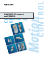
SIMODRIVE 611 universal
and POSMO A
General Motion Control Catalog
Part 3 • 2001
Catalogs of the
General Motion Control Series
General Motion Control Catalog Part 1
SIMOVERT MASTERDRIVES MC
0.75 HP to 270 HP
Order No.: DRSP-02060
General Motion Control Catalog Part 2
High Performance
Motors and Accessories
Order No.: DRSP-02062
General Motion Control Catalog Part 3
SIMODRIVE 611 universal
POSMO A
Single-Motor and Multi-Motor Drives
1.5 to 160 HP
Order No.: DRSP-02080
s
SIMODRIVE 611
universal
POSMO A
Single-Motor and
Multi-Motor Drives
1.5 HP to 160 HP
(1.1 kW to 120 kW)
Overview
Technical Data
1
2
Selection & Ordering Data
3
Motor Selection
4
General Motion Control
Catalog Part 3 × 2001
Documentation
Engineering Information
Dimension Drawings
Appendix
5
6
7
A
• The technical data, selection and ordering data (order numbers), accessories and availability are subject to alteration.
Warning!
The technical data are intended for general information.
Please observe the operating instructions and the references indicated on the products for installation, operation and maintenance.
Trademarks TM
MICROMASTER, COMBIMASTER, SIMATIC, SIMATIC HMI, SIMODRIVE, SIMOLINK, SIMOREG, SIMOVERT, SITOP and STEP are
Siemens registered trademarks.
All other products and system names in this catalog are (registered) trademarks of their respective owners and must be treated
accordingly.
• All dimensions in this catalog are stated in inches (mm).
© Siemens E&A 2000
SIMODRIVE
611 universal
POSMO A
Overview
1
1/2
1/2
Introduction
A word about Siemens
How the general information is organized
1/3
1/3
1/3
1/4
1/4
1/4
1/5
1/5
1/5
1/6
1/6
1/6
1/7
Customer service
Welcome to Siemens
The Siemens commitment to customer satisfaction
Siemens policies/protocols
Siemens credit policy
Siemens special handling
Siemens international services
Optional warranties
Siemens technical services
Siemens repairs and returns for warranty
Siemens non-warranty repairs
Siemens certified service repairs and return
Siemens emergency access
Standard terms and conditions of sale
1/8
Features
1/11
Application/product selection
1/12
Application
1/14
Guidelines
1/16
Flow diagram for selection process
Siemens General Motion Control Catalog Part 3 · 2001
1/1
SIMODRIVE™ 611 universal and POSMO™ A
Overview
SIMODRIVE
POSMO A
Introduction
■ A word about Siemens
Siemens AG
1
The parent company of Siemens Energy & Automation is
Siemens AG, headquartered in
Munich, Germany. Various Siemens divisions provide a broad
spectrum of products, systems, and services worldwide.
These include:
electronic components, medical electronics, power engineering, and automation
products and systems, as well
as public and private telecommunications networks.
Siemens’ worldwide sales exceed $70 Billion in 1999, ranking it among the world’s largest
electrical companies. Siemens
ranks second in manufacturing. Siemens employs approximately 440,000 people in 193
countries, 500 manufacturing
facilities in 50 countries on 6
continents. A leading edge
company Siemens annually
reinvests between 8–1 0% of
sales in research and development activities, ranking in the
number one position in this category, along with companies
like Intel.
Siemens Energy &
Automation, inc.
One of the largest Siemens
companies in the U.S. is Siemens Energy & Automation, Inc.
with over 9,800 employees and
annual sales in excess of $1.9
Billion.
Siemens Energy & Automation
is headquartered near Atlanta,
Georgia and has 28 U.S. manufacturing facilities. SEA’ s facilities throughout the U.S.
manufacture, market, and service a wide variety of electrical
and electronic equipment and
systems that protect, regulate,
control, distribute electric power, convert electric power to mechanical energy, and automate
various manufacturing and
industrial processes. SEA
produces 85% of its products
domestically, and markets them
worldwide.
Siemens U.S.A.
The Siemens family of more
than twenty companies, subsidiaries, affiliates, and joint
ventures in the United States is
well established and growing
with annual sales in excess of
$10.4 Billion. Siemens employs
more than 58,000 people in the
U.S., in ninety-three domestic
manufacturing facilities and
more than two-hundred thirty
sales and service locations.
1/2
Siemens General Motion Control Catalog Part 3 · 2001
Siemens Energy & Automation
products are sold in two general
market segments:
industrial and construction. Our
business units are organized
into three primary operating divisions:
Industrial Solutions & Software
Division,
Distribution Products
Division and Industrial
Systems & Service.
Industrial Solutions & Software Division business unit
The Solution Business Unit develops, engineers, manufactures, markets, and services
adjustable speed drive and automation products. Our adjustable speed drive and
automation products are among
the finest in the world. Siemens
drives have historically offered
consistently superior performance and high quality, due to
our commitment to continuous
improvement in product technologies and production processes.
SIMODRIVE
611 universal
■ How the general information is
organized
General information
Welcome to Siemens
The Siemens commitment to
customer service
Siemens policies/ protocols
Siemens credit policy
Siemens special handling
Siemens international services
Siemens technical services
Siemens repairs & returns for
warranty
Siemens non-warranty repairs
Siemens certified service
repairs and returns
Siemens emergency access
Standard terms and conditions
of sale
SIMODRIVE 611 universal and POSMO A
Overview
SIMODRIVE
611 universal
■ Welcome to Siemens
If you are a new Siemens Drive
Products customer, we thank
you for doing business with us.
We will work hard to earn your
trust and serve your company
as if it were our own! If you are
currently doing business with
us, we thank you for the opportunity to grow with you.
Based on the principle, “One
Call Does It All,” we have
brought several functions into
one operating group. Customer Service Representatives
have regional assignments and
work closely with local area
sales offices, application engineering, engineering, and our
technical service group. We
believe this will optimize your
satisfaction.
It only requires one phone call
to access any of the following:
Order entry
Scheduling
Spare parts
Expediting
Repair program
Warranty administration
Invoicing/billing
Contract administration
Return goods administration
Instruction books
Drawings/drawing transmittals
Emergency service
Claims, disputes, settlements
Technical support
Our overriding concern is your
satisfaction. This information
has been put together to communicate our policies and procedures as they pertain to our
doing business together. If you
have any questions or if you
wish to discuss any of the items
explained in the following pages, please contact your local
sales office or the Drive Products Customer Service Center.
SIMODRIVE
POSMO A
In the following pages, we refer
to domestic and international
products. The definition of these
terms is as follows:
Domestic –
Those products which are manufactured and/or inventoried in
North America.
International –
Those products which are not
inventoried in North America.
As a standard, we are referring
to domestic products and
spares. If your product or spare
does not fall into the domestic
category, please see the page
marked Siemens International
Services.
■ The Siemens commitment to
customer satisfaction
Our customer service
objective
Meet our customers’ needs and
expectations, and add value to
our services through:
1. Prompt, reliable service and
information.
2. Availability of key personnel
to quickly resolve problems.
3. Effective and efficient utilization of all resources to build a
trusting relationship with our
customers.
Our standards of service
1. Process quotations within
24-hours with the exception
of blanket, international and
custom quotations.
2. Enter sales orders within
24-hours of receipt.
Customer service
■ Siemens policies/protocols
Standard Siemens Energy &
Automation warranty
Siemens E&A warrants that on
the date of shipment to the Purchaser the goods will be of the
kind and quality described in
the initial contract, merchantable, and free of defects in
workmanship and material.
If within 12 months from date of
initial operation, but not more
than 18 months from date of
shipment by Siemens E&A, of
any item of the goods, Purchaser discovers that such item was
not as warranted above and
promptly notifies Siemens E&A
in writing thereof, Siemens E&A
shall remedy such defect by, at
Siemens E&A option, adjustment, repair or replacement of
the item and any affected part of
the goods. Purchaser shall assume all responsibility and expense for removal, reinstallation
and freight in connection with
the foregoing remedy. The
same obligations and conditions shall extend to replacement items furnished by
Siemens E&A thereunder. Siemens E&A shall have the right of
disposal of items replaced by it.
Purchaser shall grant Siemens
E&A access to the goods at all
reasonable times in order for Siemens E&A to determine any
defect in the goods. In the
event that adjustment, repair or
replacement does not remedy
the defect, Siemens E&A and
Purchaser shall negotiate in
good faith an equitable adjustment in the contract price.
Siemens E&A’ s responsibility
does not extend to any item of
the goods which has not been
manufactured and sold by Siemens E&A. Such item shall be
covered only by the express
Warranty, if any, of the manufacturer thereof.
Siemens E&A and its suppliers
shall also have no responsibility
if the goods have been improperly stored, handled or installed,
if the goods have not been operated or maintained according
to their ratings or according to
instructions in Siemens E&A or
supplier furnished manuals, or if
unauthorized repairs or modifications have been made to the
goods.
THIS WARRANTY IS EXPRESSLY IN LIEU OF ALL OTHER
WARRANTIES (EXCEPT TITLE,
INCLUDING BUT NOT LIMITED
TO IMPLIED WARRANTIES OF
MERCHANTABILITY AND FITNESS, AND CONSTITUTES
THE ONLY WARRANTY OF SIEMENS E&A WITH RESPECT TO
THE GOODS.).
The foregoing states Purchaser’s exclusive remedy against
Siemens E&A and the supplier
for any defect in the goods or for
failure of the goods to be as
warranted, whether Purchaser’s
remedy is based on contract,
warranty, failure of such remedy
to achieve its essential purpose,
tort (including negligence),
strict liability, indemnity, or any
other legal theory, and whether
arising out of warranties, representations, instructions, installations or defects from any cause.
3. Return phone calls within one
hour of receipt.
4. Make every effort to expedite
an order at a customer’s
request.
5. Issue credit memos within ten
days of receipt of material.
6. Issue invoices within 48
hours.
Siemens General Motion Control Catalog Part 3 · 2001
1/3
1
SIMODRIVE 611 universal and POSMO A
Overview
SIMODRIVE
POSMO A
Customer service
Replacement warranty
Should a remanufactured replacement of a defective item
be the solution to a warranty
claim, the remanufactured part
shall be under warranty for the
duration of the warranty of the
original item or ninety (90)
days, whichever is longer.
1
A remanufactured part (other
than original warranty replacement) carries a ninety (90) day
warranty.
■ Siemens credit policy
Our terms of payment are Net
30 Days. Invoices are normally
sent within 48 hours of shipment of goods.
Credit Memos are processed
within three days if there is no
dispute of charges. If an invoice is in dispute, our Credit
Managers and Customer Service Representatives will work
closely with you to resolve the
dispute as quickly as possible.
Should any questions or concerns arise regarding your account status, please feel free to
contact your local Sales Representative.
■ Siemens special handling
Freight
All of our original product shipments are F.O.B. point of shipment; freight charges are
prepaid and add. All spare
parts are shipped freight prepaid and add. For freight
charges on International products and parts, please refer to
the index for the listing of Siemens International Services.
Orders for customers that require specific freight carriers or
copies of freight bills, will be
shipped freight collect or third
party bill. Freight collect orders
are contingent upon freight
carrier‘s acceptance of account‘s credit.
Customer account number is
required for third party billing.
1/4
Customers that request proof of
delivery and it is proven that the
product was received by the
customer, will be charged a $50
net fee for each shipment
traced.
Emergency/expedite fees
We have several special programs in order to meet your
needs. It is of course necessary
to assess a special fee for these
services if the product is not under warranty. These fees are as
follows:
NEXT FLIGHT OUT –
Same day delivery for $300.
With this service we can receive
the order, ship the product and
have it delivered in most cases
the same day.
NEXT DAY DELIVERY –
$200 if the order is received after 4:00 PM Eastern Standard
Time.
CUSTOMER PICK UP –
There is a two (2) hour processing time. All customer pick ups
will be ready 2 hours after order
is received, and must be picked
up within 24 hours.
In addition to the special handling fees above, the purchaser
is responsible for any freight
charges associated with these
shipments if the item being
shipped is not under warranty.
Restocking charges
1. Restocking charges apply
if you:
a) Have overstocked and
wish to return goods.
b) Ordered the wrong part.
c) Initiate a job change.
2. The following charge is now
in effect: 10 % for restock of
unopened products. 15 %
additional charge for repackaging on opened products.
3. If the part has been damaged, a repair cost will be
assessed in addition to the
above restocking charge.
Siemens General Motion Control Catalog Part 3 · 2001
SIMODRIVE
611 universal
Minimum order
International repairs
Drive Products has a minimum
order policy of $100 for all domestic products and spare part
orders. If the order does not total $100 net, an additional fee
will be added to bring the total
to $100; international orders
have a minimum order of $300.
Contact your local Siemens
sales office for price & delivery.
■ Siemens international services
Siemens Energy & Automation
supports all Siemens Drive
Products in the USA, regardless
of their country of origin or model type. Certain specialty products are subject to additional
logistic requirements. Models in
this category are subject to the
following special policies.
Freight, duty and taxes
The price for international products and spare parts includes
freight, duty and taxes.
Special fees
The minimum order for international items is $250 net. If the order does not total $250, an
additional charge will be added
to bring the total order to $250.
Siemens features an international emergency warehouse
that can ship many parts within
48 hours. Most products and
parts can arrive in the United
States within 3–5 days, barring
any complications with Customs. Your customer service
representative can check to see
if your part is in stock in the
emergency warehouse. If you
order from this warehouse there
is a $250 emergency fee.
Freight, duty and taxes are still
included in the price of the part
or parts.
International warranty
Warranty for international products, spare parts and repairs
are covered under the same
policy as our domestic products.
SIMODRIVE 611 universal and POSMO A
Overview
SIMODRIVE
611 universal
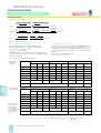
■ Optional warranties
Extended warranty
Drive Products offers an extended warranty for all products sold. The extended warranty of 12 months is
Months from
SIMODRIVE
POSMO A
offered with a surcharge of 5%
of the net price of the product.
This extended warranty offer is
only available if ordered prior to
time of original shipment from
Siemens.
Standard
warranty
Extended
warranty
installation
12
24
manufacturing
18
30
% of net
0%
5%
Deferred warranty
Siemens also offers a Deferred
Warranty for all products sold.
Commissioning must also be
purchased to inspect the condition of the drive and supervise the drive start up. This
deferred warranty offer is only
available if ordered prior to
time of original shipment from
Siemens.
The deferred warranty is offered
for those applications that will
have a delayed installation period, but only require 12 months
from the date of commissioning.
The chart below is a listing of
the warranty periods and fees
for the deferred warranty and
the extended warranty programs.
Months from
Standard
warranty
6 month
deferred
warranty
12 month
deferred
warranty
installation
12
12
12
manufacturing
18
24
30
% of net
0%
1%
2%
Customer service
■ Siemens technical services ■ Siemens repairs & returns
The Technical Service Group is
responsible for technical service support for customers, field
service, and sales engineers.
Requests for parts, equipment
commissioning, emergency
service, or routine maintenance
are coordinated and scheduled
through this group.
Service coordination and technical support for a wide variety
of drive products, including
both domestic and international
supplied units, are available
from this team. Interfacing with
the Siemens Service Organization, other Siemens Divisions,
and supplier service facilities,
this group is the single point of
contact in effectively providing
remote technical and field service support.
Over the past year, an internal
survey showed that greater than
95% of the problems called in
were resolved over the telephone. This level of technical
expertise has significantly reduced the number of on-site
service calls.
Technical Service is available
24-hours, 7 days a week by dialing 800-241-4453; ask for
Drives Technical Services and
the call will be channeled automatically through a call center
which activates the appropriate
personnel for both parts and
technical support.
for warranty
It would be wonderful if no
board ever failed or every shipment was perfect. However,
there are times when you must
return a part for repair or replacement. Following, please
find the steps you need to take
in order to return a defective
part to Siemens Energy & Automation.
Please make sure to follow
these instructions. Parts sent
back to Siemens E&A not using
the procedures outlined below
may cause your warranty to be
voided or improper credit to be
issued.
Defective part
1. Call – 800-241-4453 and ask
for Drives Technical Service,
or you may wish to send a fax
with the following information
to 770-740-3396.
a) Company Name
b) Part Number(s) of item(s)
you wish to return
c) Serial Number and
Model Number
d) Original P.O. Number or
Siemens E&A Sales Order
Number, Reason for Return
(failure symptom if applicable).
2. If you have an emergency,
e.g. your equipment is down,
and the warranty can be validated commercially, i.e., the
shipping or installation date
falls within the warranty period, we will ship a replacement part to you next day air
or next flight out at no charge
conditional on a technical validation of the warranty once
the defective item is received
in our repair department.
Please note, however, that a
conditional 30-day purchase
order for warranty replacement is required prior to shipment of any part. Should you
fail to return the defective part
within thirty (30) days upon instructions from your Sales or
Customer Service Representative, you will be invoiced in
full for the replacement part.
Siemens General Motion Control Catalog Part 3 · 2001
1/5
1
SIMODRIVE 611 universal and POSMO A
Overview
SIMODRIVE
POSMO A
Customer service
1
3. If you are not in an emergency situation, once we have
received and inspected the
defective part and validated
the technical warranty, we
will repair and return your
original product to you at no
charge. If the item is unrepairable we will immediately
send a replacement at no
charge.
4. An RGA (Return Goods
Authorization) will be issued
to you on the same day you
call. Our RGA form has
detailed instructions for the
proper return of the part to
Siemens. You are responsible for freight charges associated with any returned part
or parts. Please use antistatic bags when shipping
printed circuit boards back
to Siemens. If you do not
have anti-static bags please
let RGA Central know at the
time of your initial call and
they will provide one. If the
boards are received back
and they do not have the
proper protection from static, the warranty is null and
void. Any item received without an RGA number will be
returned to sender.
5. Our remanufactured parts
carry a full ninety (90) day
warranty or the remaining
period of your original warranty, whichever is longer.
Wrong part ordered, shipped,
overstock, etc.
If you have ordered the wrong
part, find yourself overstocked,
or a wrong part has been
shipped to you in error, please
follow these procedures:
1. Same as #1 above under
Defective Part.
2. An RGA (Return Goods Authorization) number will be
issued to you on the same
day you call. Our fax form
has detailed instructions on
how to ship the part back to
us. You are responsible for
all freight charges associated with any returned parts.
1/6
3. Parts should be returned in
their original packaging.
However, if you have opened
the package, please make
sure that the parts to be
returned are in an anti-static
bag, i.e. all boards. (If the
board is returned without this
protection, the warranty is null
and void).
4. Restocking charges – please
refer to the restocking charges under Special Handling
Charges.
Restocking charges will
apply only if the return is not
Siemens responsibility, i.e.,
wrong part ordered, overstock, exchange, etc. If the
part has been damaged, a
repair cost will be assessed
in addition to the restocking
charge.
Please note that according to
our standard terms and conditions, all claims for incorrect
items shipped must be made
within thirty (30) days after
receipt of shipment.
■ Siemens non-warranty repairs
If you have a repair that is nonwarranty, please contact your
local distributor or simply call
800-241-4453.
Siemens will fax an RGA form
with instructions on how to send
the item in for repair and return.
■ Siemens certified service
repairs and returns
If your warranty has expired,
you may still want to take advantage of our excellent repair and
return program. Highly trained
technicians perform incoming
tests to determine the exact failure, repair the equipment, and
fully test prior to shipment back
to you.
Siemens General Motion Control Catalog Part 3 · 2001
However, if you elect, in some
instances, we may be able to
send you a remanufactured part
for 60% of the list price of a new
part less your applicable discount on an exchange basis.
Remanufactured parts carry a
ninety (90) day warranty. Your
sales or customer service representative can tell you which
parts are included in our repair/
return program.
Should you take advantage of
this program, please note that if
you fail to return the original part
to us within ten (10) days, you
will be invoiced for the balance
of a new board, which is 40%.
Of course, you can always purchase a new part at your option!
If you have an emergency and
you are down, we have two excellent emergency programs.
(Please note – expedite fees do
not apply to parts under warranty):
1. NEXT FLIGHT OUT –
Most of our products and
spare parts can be shipped
from our Emergency Depot
located at Atlanta Hartsfield
International Airport. These
parts go next flight out and for
most areas of the country are
received the same day. There
is a $300 expedite charge for
this service plus any freight
charges associated with the
shipment.
2. NEXT DAY AIR –
You will receive your part the
following day, depending on
the location of the ship-to address. There is a $200 expedite charge for this service
plus any freight charges associated with the order, if the
order is received at our office
after 4:00 PM Eastern Standard Time.
SIMODRIVE
611 universal
■ Siemens emergency access
The Drive Products Business
Unit has an emergency spare
parts depot at Atlanta Hartsfield
International Airport. Same day
delivery requirements are often
serviced out of this Depot as
well as after hour shipments
including weekends and holidays. This has allowed us to expedite emergency shipment,
saving several hours in the
process.
To activate our Emergency/
After Hours Service, simply dial
800-241-4453 and ask for
Drives Technical Service and
the call will be automatically
transferred to our message service, who will in turn page the
On-Call Representative.
Tell the operator there is an
emergency and you would like
to contact after hour’s personnel
for spare parts or technical
service, and we will return your
call immediately.
Technical assistance
When the Technical Service Department, which is responsible
for technical support, is unavailable, a reliable answering service ensures that a technical
service request is relayed immediately to one of our engineers on call. Should you need
technical assistance (other than
ordering a part) please call
1-800-241-4453; this toll free
number provides day and
night access to our Corporate
Field Service Organization.
SIMODRIVE 611 universal and POSMO A
Overview
SIMODRIVE
611 universal
SIMODRIVE
POSMO A
Customer service
■ Standard terms and conditions of sale (1/1/2000)
Siemens Energy & Automation, Inc. ("Seller")
1. WARRANTY (a) Seller warrants that on the date of shipment the goods are of the kind and
quality described herein and are free of non-conformities in workmanship and
material. This warranty does not apply to goods delivered by Seller but manufactured by others.
(b) Buyer’s exclusive remedy for a nonconformity in any item of the goods shall
be the repair or the replacement (at Seller’s option) of the item and any affected part of the goods. Seller’s obligation to repair or replace shall be in effect
for a period of one (1) year from initial operation of the goods but not more
than eighteen (18) months from Seller’s shipment of the goods, provided Buyer has sent written notice within that period of time to Seller that the goods do
not conform to the above warranty. Repaired and replacement parts shall be
warranted for the remainder of the original period of notification set forth
above, but in no event less than 12 months from repair or replacement. At its
expense, Buyer shall remove and ship to Seller any such nonconforming
items and shall reinstall the repaired or replaced parts. Buyer shall grant Seller access to the goods at all reasonable times in order for Seller to determine
any nonconformity in the goods. Seller shall have the right of disposal of items
replaced by it. If Seller is unable or unwilling to repair or replace, or if repair
or replacement does not remedy the nonconformity, Seller and Buyer shall
negotiate an equitable adjustment in the contract price, which may include a
full refund of the contract price for the nonconforming goods.
(c) SELLER HEREBY DISCLAIMS ALL OTHER WARRANTIES, EXPRESS OR IMPLIED, EXCEPT THAT OF TITLE. SPECIFICALLY, IT DISCLAIMS THE IMPLIED WARRANTIES OF MERCHANTABILITY, FITNESS FOR A PARTICULAR
PURPOSE, COURSE OF DEALING AND USAGE OF TRADE.
(d) Buyer and successors of Buyer are limited to the remedies specified in this
article and shall have no others for a nonconformity in the goods. Buyer
agrees that these remedies provide Buyer and its successors with a minimum
adequate remedy and are their exclusive remedies, whether Buyer’s or its
successors’ remedies are based on contract, warranty, tort (including negligence), strict liability, indemnity, or any other legal theory, and whether arising out of warranties, representations, instructions, installations, or nonconformities from any cause.
(c) If any time in Seller’s judgment Buyer is unable or unwilling to meet the terms
specified, Seller may require satisfactory assurance or full or partial payment
as a condition to commencing or continuing manufacture or making shipment, and may, if shipment has been made, recover the goods from the carrier, pending receipt of such assurances.
7. NONCANCELLATION - Buyer may not cancel or terminate for convenience, or
direct suspension of manufacture, except with Seller’s written consent and then
only upon terms that will compensate Seller for its engineering, fabrication and
purchasing charges and any other costs relating to such cancellation, termination or suspension, plus a reasonable amount for profit.
8. NUCLEAR - Buyer represents and warrants that the goods covered by this contract shall not be used in or in connection with a nuclear facility or application. If
Buyer is unable to make such representation and warranty, then Buyer agrees to
indemnify and hold harmless Seller and to waive and require its insurers to waive
all right of recovery against Seller for any damage, loss, destruction, injury or
death resulting from a "nuclear incident", as that term is defined in the Atomic Energy Act of 1954, as amended, whether or not due to Seller’s negligence.
9. LIMITATION OF LIABILITY - Neither Seller, nor its suppliers shall be liable,
whether in contract, warranty, failure of a remedy to achieve its intended or essential purposes, tort (including negligence), strict liability, indemnity or any other legal theory, for loss of use, revenue or profit, or for costs of capital or of
substitute use or performance, or for indirect, special, liquidated, incidental or
consequential damages, or for any other loss or cost of a similar type, or for
claims by Buyer for damages of Buyer’s customers. Seller’s maximum liability under this contract shall be the contract price. Buyer and Seller agree that the exclusions and limitations set forth in this article are separate and independent from
any remedies which Buyer may have hereunder and shall be given full force and
effect whether or not any or all such remedies shall be deemed to have failed of
their essential purpose.
10. GOVERNING LAW AND ASSIGNMENT - The laws of the State of Georgia shall
govern the validity, interpretation and enforcement of this contract, without regard to its conflicts of law principles. The application of the United Nations Convention on Contracts for the International Sale of Goods shall be excluded.
Assignment may be made only with written consent of both parties; provided,
however, Seller may assign to its affiliate without Buyer’s consent.
(e) Note: This article 1 does not apply to any software which may be furnished by
Seller. In such cases, the attached Software License Addendum applies.
11. ATTORNEY FEES - Buyer shall be liable to Seller for any attorney fees and costs
incurred by Seller in enforcing any of its rights hereunder.
2. PATENTS - Seller shall pay costs and damages finally awarded in any suit
against Buyer or its vendees to the extent based upon a finding that the design
or construction of the goods as furnished infringes a United States patent (except
infringement occurring as a result of incorporating a design or modification at
Buyer’s request), provided that Buyer promptly notifies Seller of any charge of infringement, and Seller is given the right at its expense to settle such charge and
to defend or control the defense of any suit based upon such charge. Seller shall
have no obligation hereunder with respect to claims, suits or proceedings, resulting from or related to, in whole or in part, (i) the use of software or software documentation, (ii) compliance with Buyer’s specifications, (iii) the combination with,
or modification of, the goods after delivery by Seller, or (iv) the use of the goods,
or any part thereof, in the practice of a process. THIS ARTICLE SETS FORTH
SELLER’S ENTIRE LIABILITY WITH RESPECT TO PATENTS.
12. DISPUTES - Either party may give the other party written notice of any dispute
arising out of or relating to this contract and not resolved in the normal course of
business. The parties shall attempt in good faith to resolve such dispute promptly
by negotiations between executives who have authority to settle the dispute. If
the matter has not been resolved within 60 days of the notice, either party may
initiate non-binding mediation of the dispute.
3. PERFORMANCE; DELAYS - Timely performance by Seller is contingent upon
Buyer’s supplying to Seller, when needed, all required technical information and
data, including drawing approvals, and all required commercial documentation.
If Seller suffers delay in performance due to any cause beyond its reasonable
control, the time of performance shall be extended a period of time equal to the
period of the delay and its consequences. Seller will give to Buyer notice within
a reasonable time after Seller becomes aware of any such delay.
4. SHIPMENT, TITLE AND RISK OF LOSS (a) The term "shipment" means delivery to the initial carrier in accordance with the
delivery terms of this contract. Seller may make partial shipments. Seller shall
select method of transportation and route, unless terms are f.o.b point of shipment and Buyer specifies the method and route and is to pay the freight costs
in addition to the price. When terms are f.o.b. destination or freight allowed to
destination, "destination" means common carrier delivery point (within the
United States, excluding Alaska and Hawaii) nearest the destination.
(b) Title to the goods and risk of loss or damage shall pass to Buyer at the f.o.b.
point. Seller shall not be responsible for damage to the goods after having received "in good order" receipts from the carrier.
5. TAXES - Any applicable duties or sales, use, excise, value-added or similar taxes will be added to the price and invoiced separately (unless an acceptable exemption certificate is furnished).
6. TERMS OF PAYMENT (a) Unless otherwise stated, all payments shall be in United States dollars, and a
pro rata payment shall become due as each shipment is made. If shipment is
delayed by Buyer, date of notice of readiness for shipment shall be deemed
to be date of shipment for payment purposes.
(b) On late payments, the contract price shall, without prejudice to Seller’s right
to immediate payment, be increased by 1 1/2% per month on the unpaid balance, but not to exceed the maximum permitted by law.
13. STATUTE OF LIMITATIONS - To the extent permitted by applicable law, any
lawsuit for breach of contract, including breach of warranty, arising out of the
transactions covered by this contract, must be commenced not later than twelve
(12) months from the date the cause of action accrued.
14. PRICES - In the event of a price increase or decrease, the price of goods on order will be adjusted to reflect such increase or decrease. This does not apply to
a shipment held by request of Buyer. Goods already shipped are not subject to
price increase or decrease. Orders on a bid or contract basis are not subject to
this article. Orders amounting to less than $100.00 net will be invoiced at $100.00
plus transportation charges for goods covered by discount schedules. Seller’s
prices include the costs of standard domestic packing only. Any deviation from
this standard packing (domestic or export), including U.S. Government sealed
packing, will result in extra charges. To determine such extra charges, consult
Seller’s sales offices.
15. ADDITIONAL TERMS OF PAYMENT (a) Invoice payment terms are as shown on latest discount sheets as issued from
time to time. Cash discounts are not applicable to notes or trade acceptances, to prepaid transportation charges when added to Seller’s invoices or to
discountable items if there are undisputed past due items on the account.
Portions of an invoice in dispute should be deducted and the balance remitted with a detailed explanation of the deduction. Cash discounts will only be
allowed on that portion of the invoice paid within the normal discount period.
(b) Freight will be allowed to any common-carrier free-delivery point within the
United States, excluding Alaska and Hawaii, on shipments exceeding $1,000
net or more providing Seller selects the carrier. On shipments to Alaska and
Hawaii, freight will be allowed to dockside at the listed port of debarkation
nearest the destination point on shipments of $1,000 net or more. Buyer shall
pay all special costs such as cartage, stevedoring and insurance. Special
freight allowances are as shown on latest discount sheets as issued from time
to time. Cataloged weights are estimated, not guaranteed. Seller assumes no
responsibility for tariff classifications on carriers.
16. CHANGES IN LAWS AND REGULATIONS - Seller’s prices and timely performance are based on all applicable laws, rules, regulations, orders, codes, standards or requirements of governmental authorities effective on the date of
Seller’s proposal. Any change to any law, rule, regulation, order, code, standard
or requirement which requires any change hereunder shall entitle Seller to an equitable adjustment in the prices and any time of performance.
Siemens General Motion Control Catalog Part 3 · 2001
1/7
1
SIMODRIVE 611 universal and POSMO A
Overview
SIMODRIVE
POSMO A
Features
SIMODRIVE
611 universal
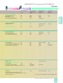
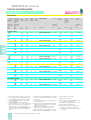
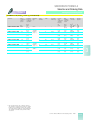
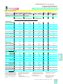
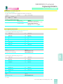
■ Comparison between SIMOVERT MASTERDRIVES MC, SIMODRIVE 611 universal and SIMODRIVE POSMO A
1
Feature
SIMOVERT™
MASTERDRIVES MC
SIMODRIVE
611 universal
SIMODRIVE
POSMO A
AC – AC
Yes
N/A
N/A
DC – AC
Yes
Yes
Yes
Output range
0.75 – 335 HP (0.55 – 250 kW)
1.5 – 163 HP (1.1 – 120 kW)
0.1 HP (75 W)
Voltage ratings
380 – 460 V ± 15 %
400 – 460 V + 6 % – 10 %
24 V DC ± 20 %
Frequency range
50/60 Hz ± 6 %
50/60 Hz ± 5 %
N/A
Output frequency capability
0 – 400 Hz
0 – 1400 Hz
N/A
Max. output voltage
86 % of input voltage (AC)
86 % of input voltage (AC)
N/A
32 °F to 104 °F (0 °C to 40 °C)
32 °F to 113 °F (0 °C to 45 °C)
64 % of input voltage (DC)
Ambient temperature rating
104 °F (40 °C)
Compact & CHASSIS
113 °F (45 °C)
Compact PLUS
With derating up to 122 °F (50 °C) With derating up to 113 °F (45 °C) With derating up to 149 °F (65 °C)
Overload capability
160 % x Rated output current (In)
for 30 s
Cycle time: 300 s
200 % x Rated output current (In)
for 2.65 s
Cycle time: 10 s
200 % x Rated torque for 15 s
98 %
65 %
N/A
Planetary gearbox:
– Single stage i = 4.5 and 8
– Two stage i = 20.25, 36 and 50
– Three stage i = 126.56 and 162
Cycle time: 60 s
or
300 % x Rated output current (In)
for 250 ms on Compact PLUS
Cycle time: 1 s
Inverter efficiency
96 – 98 %
Compact & CHASSIS
93 – 96 %
Compact PLUS
Gearboxes
N/A
Worm Gear:
– Single stage i = 5 and 24
Motors which can be
connected
1/8
SIEMENS synchronous
servo motors e.g. 1FT6; 1FK6
SIEMENS synchronous
servo motors e.g. 1FT6; 1FK6
SIEMENS asynchronous
servo motors e.g. 1PH
SIEMENS asynchronous
servo motors e.g. 1PH
SIEMENS induction motors
e.g. 1LA; RGZESDI
SIEMENS induction motors
e.g. 1LA; RGZESDI
Standard inverter rated NEMA
induction motor
SIEMENS linear motors e.g. 1FN
Siemens General Motion Control Catalog Part 3 · 2001
N/A
SIMODRIVE 611 universal and POSMO A
Overview
SIMODRIVE
611 universal
SIMODRIVE
POSMO A
Features
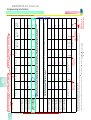
■ Comparison between SIMOVERT MASTERDRIVES MC, SIMODRIVE 611 universal and SIMODRIVE POSMO A
Feature
SIMOVERT
MASTERDRIVES MC
SIMODRIVE
611 universal
SIMODRIVE
POSMO A
V/Hz
Standard
Standard
N/A
V/Hz w/Slip compensation
N/A
N/A
N/A
V/Hz – Textile mode
N/A
N/A
N/A
Open loop vector
N/A
N/A
N/A
Closed loop speed
Standard
Standard
Standard
Torque control
Standard
Standard
N/A
Digital inputs/outputs
2 dedicated inputs (24 V)
4 inputs
2 configurable input/output
4 configurable input/output
4 outputs
Analog inputs
(1) ±10 V
(2) ±10 V
Resolution
10 – BIT + SIGN
13 – BIT + SIGN
Analog outputs
(1) ±10 V
(2) ±10 V
Resolution
8 – BIT + SIGN
7 – BIT + SIGN
Skip frequency
No
Yes
N/A
Band stop filter
1
2
N/A
Fixed frequencies
16
N/A
N/A
Fault memory
Last 8 occurrences
(max. 8 faults per occurrence)
Yes
No
Warning alarm
Yes
Yes
Yes
Motor protection
I2t protection (PTC/thermistor)
I 2t protection (PTC/thermistor)
I 2t protection
Automatic tune
Motor ID, & current loop
Yes
Pre-tuned ex-work
Communication types
– USS (standard (2)
RS232/485 ports)
– Analog (standard)
– *PROFIBUS (up to 12 MB)
– standard (2)
RS232/485 ports)
– Analog (standard)
– *PROFIBUS (up to 12 MB)
N/A
– *SIMOLINK
(Peer to Peer/synchronization)
– *CAN
– *Device net
– *CC – link
N/A
N/A
N/A
N/A
N/A
N/A
N/A
N/A
5 – 8 kHz
2 – 8 kHz
N/A
Type of control
*Optional communication
board required
Carrier frequency
1
N/A
N/A
N/A
– PROFIBUS DP up to 12 MB
5 – 6 kHz (with technology option) 3.2 kHz recommended
for induction motors
4.0 kHz recommended
for synchronous motors
PID control
Yes – full function
N/A
N/A
Braking capability
Optional pulse resistor braking or
regenerative (brake chopper
integrated in AC – AC Compact
PLUS units
Optional pulse resistor braking or
regenerative (holding braking
management integrated)
Optional external Power
Management Module
Built-in resistor for 6.5 and 13.5 HP
(5 and 10 kW)
O/I modules
Siemens General Motion Control Catalog Part 3 · 2001
1/9
SIMODRIVE 611 universal and POSMO A
Overview
SIMODRIVE
POSMO A
Features
SIMODRIVE
611 universal
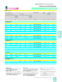
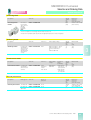
■ Comparison between SIMOVERT MASTERDRIVES MC, SIMODRIVE 611 universal and SIMODRIVE POSMO A
1
Feature
SIMOVERT
MASTERDRIVES MC
SIMODRIVE
611 universal
SIMODRIVE
POSMO A
“S” Curve acceleration
Yes with comfort ramp-function
generator (free function block)
Yes
Ramp up time setting
Hoist brake interface
Standard
Standard
N/A
Standard keypad
6-button,
4-digit, 7-segment red LED‘s
3-button,
6-digit, 7-segment
N/A
N/A
N/A
3-button on compact PLUS unit
Optional keypad
LCD multi-language text display
BUS master/direct parameter
access
Parameter storage
Firmware upgrade via
flash e2prom
Standard
Standard
N/A
Field-weakening operation
range for induction motors
1:2
1 : 16
N/A
Position control
With technology option
Yes
Yes
Electronic line shaft via
fiberoptic cable
Yes
(using SIMOLINK)
N/A
N/A
Positioning update time
1.6 ms
1 ms
10 ms
Current update time
0.2 ms
31.5 ms
125 ms
Speed update time
0.4 ms
0.25 ms
1 ms
Agency compliance
UL listed, CSA, CE
UL listed, CSA, CE
UL listed, CE
Application
Electronic line shaft
Point to point positioning
Positioning of formats or end stop
Examples/guidelines
Web handling w/synchronization
Point to point positioning
Cut-to-length applications
Search for reference
Automatic positioning
Positioning of process variables
(e.g. by means of motorized
valves)
1/10
Siemens General Motion Control Catalog Part 3 · 2001
SIMODRIVE 611 universal and POSMO A
Overview
SIMODRIVE
611 universal
SIMODRIVE
POSMO A
Application/product selection
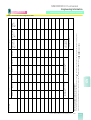
■ Selection guideline for Siemens, non-machine tool, motion control solutions
General Motion Control
Functions
MC*
MC
+ Technology
SIMODRIVE
POSMO A
SIMODRIVE
611 universal
FM 357
+ 611 u
Handling
1
Axis Coordination
• Coordinate transformation
• Circular interpolation 2D/3D
• Linear interpolation 2D/3D
Synchronization
• Linear interpolation 2D
• Print mark registration
• Engage/Disengage
• CAM Profile
• Electronic gear
Positioning
• Virtual master
• Roll feed (Continuous positioning)
• Automatic mode
• MDI (Point-to-Point positioning)
Basic functions
• Referencing (Homing)
• Linear/rotary axis
• Position regulator
• Speed regulator
• Current regulator
* Simple positioning with V 1.5 and greater.
Siemens General Motion Control Catalog Part 3 · 2001
1/11
SIMODRIVE 611 universal and POSMO A
Overview
SIMODRIVE
POSMO A
Application
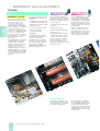
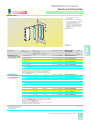
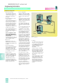
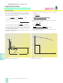
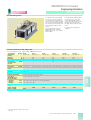
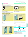
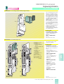
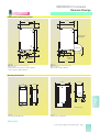
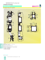
■ SIMODRIVE 611 universal
1
With a proven hardware platform in the machine tool industry, the new 611 U (U for
“Universal”) has been designed to handle a range of
General Motion Control applications. Capable of controlling
various motor types, be it
Synchronous Servo, Asynchronous Servo, standard Induction
or Linear. Its compact multiaxis design is well suited for
many industries – i.e. printing,
packaging, textile, wood,
glass, etc.
The SIMODRIVE 611 universal
is supplied for line voltages of
3-phase 380 V to 480 V AC,
50/60 Hz and is available from
1.5 HP to 160 HP (1.1 to
120 kW). The modules have a
standard design of 19 inches
(480 mm) high by 11.5 inches
(288 mm) deep and depending
on the power range, the width
increases in units of 2 inches
(50 mm).
Some of the main features of the
SIMODRIVE 611 universal are
as follows:
• configurable for speed/torque
control and positioning control
• suitable for synchronous and
induction motors
• compact design with 1-axis
and 2-axis modules
• communication with
PROFIBUS
• and all data in the package
present on a transferable
memory submodule
In addition to classical drive
functions such as torque and
speed control with output frequencies up to 1400 Hz,
SIMODRIVE 611 U offers integral positioning functions.
Up to 64 independent traversing blocks can be stored to perform either absolute or relative
position moves allowing it to be
characterized by
• extremely high dynamic performance
• flexible positioning
• high field weakening range
• and ease of use.
The program is rounded off by a
complete spectrum of system
components and accessories.
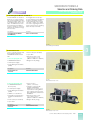
SIMODRIVE
611 universal
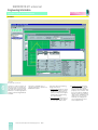
For the SIMODRIVE 611 universal, an easy to use Windows
based graphical programming
and diagnostic tool is available.
Known as SIMOCOM U, this tool
has been specially developed
to make start up of the drive system effortless.
Siemens‘ world-wide service
and the company‘s sales network enable all our customers to
obtain direct access to expert
advice and project planning as
well as training and service.
Customer specific, integral solutions (automation – drives –
motors) are available for the
most varied of applications in all
industrial sectors.
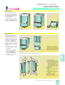
Customized Solutions
The drives are available internally cooled, externally cooled,
or via external hose cooling to fit
all cabinet configurations.
1/12
Siemens General Motion Control Catalog Part 3 · 2001
Infeed modules are available
as unregulated rectifiers up to
13.5 HP (10 kW) utilizing pulsed
resistors to dissipate excess
energy. Above 13.5 HP (10 kW)
regulated regenerative units are
utilized to return excess energy
to the supply.
SIMODRIVE 611 universal and POSMO A
Overview
SIMODRIVE
611 universal
SIMODRIVE
POSMO A
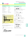
Application
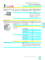
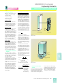
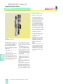
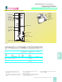
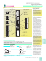
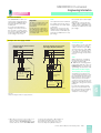
Main features:
• Power section and entire
movement control in the motor
• Linking via communication
and power bus
• PROFIBUS-DP standard slave
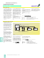
With its well designed distributed concept, SIMODRIVE
POSMO A opens up a new level
in automation.
Typical applications are the:
• Adjustment of formats or end
stops
• Setting of process variables,
for example via motorized
valves
Improved production costs:
■ SIMODRIVE POSMO A
To increase productivity in production, it requires optimization
of such factors as throughput,
availability and machine price.
Positioning plays a significant
role.
SIMODRIVE POSMO A
(Actuator) is an intelligent positioning motor and is a participant on a PROFIBUS-DP
distributed network.
Lower engineering costs can be
achieved through the distributed drive architecture. Production time can be improved due
to short set-up times and automated process variable settings
through intelligent movement
control.
SIMODRIVE POSMO A functions well in machines for packaging, wood, glass, printing,
plastics, and transfer lines. They
are also used in medical diagnostics for moving table tops or
X-ray equipment.
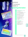
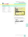
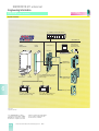
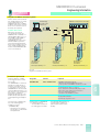
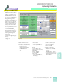
Optimal integration of drives into the world of automation
SIMATICTM HMI
PC/PG
SIMATIC S7/M7/FM
PROFIBUS-DP/MC
SIMOLINK
TM
GMC-5005a
MICROMASTER
MICROMASTER TM
COMBIMASTER TM
Open Loop Control
SIMOREG TM
DC MASTER
MASTERDRIVES VC
Closed Loop Control
MASTERDRIVES MC
Motion Control
POSMO A SIMODRIVE
611 universal
SIMODRIVE
CNC drives
Siemens General Motion Control Catalog Part 3 · 2001
1/13
1
SIMODRIVE 611 universal and POSMO A
Overview
SIMODRIVE
POSMO A
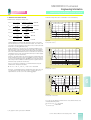
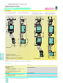
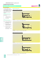
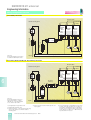
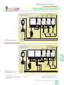
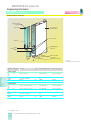
Guidelines
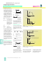
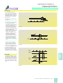
1-phase AC supply
SIMODRIVE
611 universal
3-phase AC supply
1
regulated/
regenerative
6MC-513g
unregulated/
non-regenerative
1-axis
1/14
Siemens General Motion Control Catalog Part 3 · 2001
2-axis
SIMODRIVE 611 universal and POSMO A
Overview
SIMODRIVE
611 universal
SIMODRIVE
POSMO A
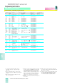
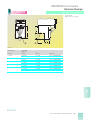
Technical data
Guidelines
Page
Selection and
ordering data
Page
Engineering
information
Page
Dimension
drawings
Page
Line-side components
Commutating reactors
Mains filters
Mains filter package
Overvoltage limiter module
2/6
2/6
–
2/6
3/10
3/10
3/10
3/5
6/27
6/28
6/29
6/29, 6/53
7/5
7/5
–
–
Infeed modules
Rectifier and rectifier/
regenerative unit
2/3
3/2
6/30, 6/31, 6/47,
6/51, 6/52
7/6, 7/9
SITOP Power supply
2/9
3/16
6/73
–
System components
Monitoring module
Pulse resistor module
Power Management Module
2/6
2/5
2/9
3/5
3/5
3/15
6/33, 6/60
6/34, 6/35
6/75
7/2
7/3
–
Power sections
Power modules
Power modules internally cooled
Power modules externally cooled
Power modules host cooled
2/4
2/4
2/4
–
3/3
3/3
3/3
3/3
6/31, 6/49, 6/50
6/31
6/37
6/38
7/2
7/2
7/9 – 7/13
7/7, 7/8
Electronic options
Plug-in units
–
–
6/32, 6/53 – 6/59
–
Interconnecting components
Power cables
2/10
Power and encoder cables
2/10
PROFIBUS cables and connectors 2/11, 2/12
3/13
6/63, 6/64
3/13, 3/14
–
6/63, 6/64
–
–
–
–
Motors
POSMO A
3/13
3/12, 6/73 – 6/86
7/16
2/7
1FK6 and 1FT6 synchronous motors,
1PH7, 1PL6 and 1PH4 compact induction motors,
1FN3 linear motors
1
see Siemens General Motion Control Catalog, Part 2
Siemens General Motion Control Catalog Part 3 · 2001
1/15
SIMODRIVE 611 universal and POSMO A
Overview
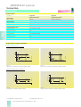
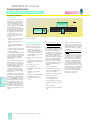
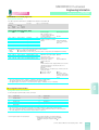
Flow diagram for
SIMODRIVE 611 universal selection process
SIMODRIVE
POSMO A
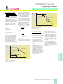
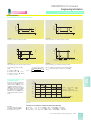
Mandatory
information
SIMODRIVE
611 universal
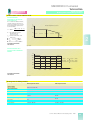
Speed [rpm] n
It is necessary to know the specific speed
and load cycle of your application in order
to select a proper drive and motor.
1
t1
T
t i-1
ti
t
rated
ADA65-5775
Torque
t
Step 1
see section 7 for details
Step 2
Determine supply voltage:
380 to 400 V; 460 to 480 V
Step 3
Determine type of construction:
see section 7 for details
IM B 3 (foot mounting); IM B 5 (flange mounting); IM B 35 (foot/flange mounting)
Step 4
Determine maximum torque from load cycle profile:
Step 5
Determine mean (RMS) torque:
see section 7 for calculation
Step 6
Determine type of motor needed (synchronous/asynchronous):
1FK6; 1FT6; 1PH7; 1PL6; 1PH4; 1FN3
see overview in section 1
Step 7
Select motor from appropriate data page (section 2 or 3)
that fulfill the following criteria
Synchronous motors:
Asynchronous motors:
nmax £ nrated; tmax < 2 x trated
nmax £ nrated
tRMS £ trated
tRMS £ trated
Points of cycle (ni, ti) must be in
Points of load (ni, ti) must be below
intermittent operating region
breakdown torque curve by a minisee graphs in section 7.
mum clearance of 30 %.
See section 7.
Step 8
Determine the kind of feedback device required:
see section 4 for details
Pulse encoder (only induction motor); resolver; sin/cos encoder; absolute value encoder
Step 9
Complete motor part number based on options required:
1FK6; 1FT6;1PH7; 1PL6; 1PH4; 1FN3
see section 2 or 3 for details
Order Number Motor:
1FK6 ¨¨¨-¨¨¨¨¨-¨¨¨¨
1FT6 ¨¨¨-¨¨¨¨¨-¨¨¨¨
1PH7 ¨¨¨-¨¨¨¨¨-¨¨¨¨
1PL6 ¨¨¨-¨¨¨¨¨-¨¨¨¨
1PH4 ¨¨¨-¨¨¨¨¨-Option + codes
1FN3 ¨¨¨-¨¨¨¨¨-¨¨¨¨
Step 10
Determine the length and size of prefabricated power cable
required or determine size of coupling for customer assembly:
see section 5 for details and part number configuration
Order Number Power Cable:
Step 11
1/16
Siemens General Motion Control Catalog Part 3 · 2001
HIGH PERFORMANCE MOTORS AND ACCESSORIES CATALOG
Determine degree of protection:
IP 23; IP 55; IP 64; IP 65; IP 67
SIMODRIVE 611 universal and POSMO A
Overview
SIMODRIVE
611 universal
SIMODRIVE
POSMO A
Flow diagram for selection process
Step 11
Determine the length and size of prefabricated signal cable required or determine
size of coupling for customer assembly:
a) Resolver
b) Sin/cos encoder
c) Absolute value encoder
see section 5 for details
1
Step 12
Select Power Module based on calculated motor currents
see example section 6 for eng. details
Choose 1-axis or 2-axis plug-in unit
With resolver or sin/cos-feedback
speed/torque or position control
see example section 6 for eng. details
Step 14
Repeat step 12 and 13 for all axes of application
Step 15
Calculate total DC link power PDClink
Planning sheet
see example section 6 for eng. details
Step 16
Check total:
a) DC link capacitance (charging limit)
b) Power supply rating for 24 V DC
see assessment and configuration sheat
section 6 for eng. details
Step 17
Select
Infeed module based on calculated total DC link power
Step 18
Determine if pulse resistor module and resistor is needed
Required only for O/I (non regenerative) unit
see section 6 for eng. details
Determine if below components are necessary and choose
a) Appropriate HF commutating reactor
b) Mains filter module according to I/RF (regenerative) rated or
O/I (non regenerative) rated power
c) Monitoring modules according electronic points
see section 6 for eng. details
Step 19
Step 20
Determine if PROFIBUS communication or additional inputs/outputs are required
GENERAL MOTION CONTROL CATALOG PART 3
Step 13
Step 21
Select any other additional equipment i.e. bus cable;
Two tier module; shield terminal plate etc.
see section 3 for order details
Step 22
See ordering example in section 6
Siemens General Motion Control Catalog Part 3 · 2001
1/17
SIMODRIVE 611 universal and POSMO A
Overview
SIMODRIVE
POSMO A
Notes
1
1/18
Siemens General Motion Control Catalog Part 3 · 2001
SIMODRIVE
611 universal
SIMODRIVE
611 universal
POSMO A
Technical Data
2/2
2/3
2/4
2/5
2/6
2/6
2/6
2/6
SIMODRIVE 611 universal
General technical data
Infeed modules
Power modules
Braking units and braking resistors
HF commutating reactors
Mains filters
Monitoring module
Overvoltage limiter module
2/7
2/9
2/9
2/10
2/11
2/12
SIMODRIVE POSMO A
General technical data
SITOPTM 24 V Power supply standard type
Power management module (PMM)
Power cable
Bus connectors
LAN cables
Siemens General Motion Control Catalog Part 3 · 2001
2
2/1
SIMODRIVE 611 universal
Technical Data
General technical data
SIMODRIVE 611 universal
2
SIMODRIVE
611 universal
EU low-voltage directive
73/23/EWG and RL 93/68/EWG
EN 50 178
EU-EMC directive
89/336/EWG
EMC product standard EN 55 011 for variable-speed drives
EC machine guideline
89/392/EC
Safety category 3 according to Y54-1
Approvals
UL/CSA
EN
CUL
Pollution degree
Pollution degree 2 in accordance with EN 50 178
moisture condensation not permissible
Overvoltage category
Category III to DIN VDE 0110, Part 2
Degree of protection
To EN 60 529 IP 201)
Insulation test voltage
2.5 kV
Shock protection (Impact load)
Acceleration 160.93 ft/s2 (49.05 m/s2) for 11 ms according to
EN 60 068-2-27 (IEC 68, Part 2-27)
Radio interference
• Standard
• Options
To EN 61 800-3
No radio-interference suppression
Radio-interference suppression filter for Class B1 or A1 in accordance with EN 55 011
Vibration stress
• Acceleration
To DIN IEC 68-2-6
32 ft/s2 (9.8 ms–2) in accordance to EN 60 068-2-6 with constant deflection of 0.075 mm
in the frequency range 10 Hz to 58 Hz
Environmental conditions
to DIN EN 60 721-3-3
Climate 3K5
Cooling type
Forced air cooling with integral fan.
Externally cooled by blower or by external duct.
Permissible ambient and
cooling medium temperature
• During operation
• During storage and transport
+32 °F to +104 °F (0 °C to 40 °C)2)
–40 °F to 158 °F (–40 °C to +70 °C)
Installation altitude
3281 ft (1000 m) above sea level
Permissible moisture conditions
Relative humidity 95 % during operation;
moisture condensation not permissible
1) Applicable to power modules only when
closed-loop control plug-in units is inserted.
2/2
2) With derating to +131 °F (+55 °C).
Siemens General Motion Control Catalog Part 3 · 2001
SIMODRIVE 611 universal
Technical Data
SIMODRIVE
611 universal
Infeed modules
■ Infeed modules
Unregulated
O/I (aka. U/E) module1)
Regulated
I/RF (aka. I/R) module2)
Rated voltage
Line voltage
400 V – 10 % to 480 V + 6 % 3-phase AC
Output voltage (DC link voltage)
490 V to 680 V + 6 % DC
Rated frequency
Line frequency
50 Hz to 60 Hz ± 10 %
Power factor
• fundamental
• overall
0.87
0.67
600 V/625 V 680 V DC selected via switch
0.98
0.97
» 0.98
Efficiency
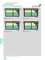
■ Infeed modules overload characteristic
2
Rated load duty cycles
P
Ps6
Pn
0.4 Pn
Ps6
Pn
0.4 Pn
GMC-5016
Pmax
4 min
10 s
t
10 min
GMC-5017
P
Pmax
t
60 s
Fig. 2/1
S6 duty cycle with pre-loading condition
Fig. 2/2
Peak output duty cycle with pre-loading condition
GMC-5019
P
F Pn
GMC-5018
P
Pmax
Pn
Pn
4s
0.2 s
t
10 s
t
10 s
F: For all infeed modules up to Pn £ 109 HP (80 kW), F = 1.6
For Pn = 160 HP (120 kW), F = 1.4
Fig. 2/3
Peak output duty cycle with pre-loading condition
Fig. 2/4
Peak output duty cycle without pre-loading condition
Derating as a function of the installation altitude
XH
100%
GMC-5020b
80%
Pn altitude
60%
= X H Pn 1000 m
PnS6 altitude = X H Ps6 1000 m
/100%
/100%
Pmax. altitude = X H Pmax. 1000 m /100%
40%
20%
0%
0
3281
1000
6562
2000
9843
3000
13124
4000
16405 Installation altitude ft (m)
5000
For detailed information
see section 6
Fig. 2/5
1) Unregulated/non regenerative unit
2) Regulated/regenerative unit
Siemens General Motion Control Catalog Part 3 · 2001
2/3
SIMODRIVE 611 universal
Technical Data
SIMODRIVE
611 universal
Power modules
■ Power modules
Used with
Unregulated
O/I (aka. U/E) module1)
Regulated
I/RF (aka. I/R) module2)
Rated voltage
DC link voltage
490 V DC
600 V/625 V/680 V DC
Output voltage
0 to 400 V 3-phase AC
0 to 430 V 3-phase AC
Rated frequency
Output frequency / max. digital resolution
0 to 1400 Hz
Rated motor output
1.5 HP to 163 HP (1.1 kW to 120 kW)
Load class
Cold start load duty cycle
Overload current
2 x In (continuous current)
Overload duration
2.65 s
Overload cycle time
10 s
Load duty cycle
2 x In (continuous current)
Overload duration
0.25 s
Overload cycle time
10 s
Efficiency
0.98
■ Power modules, overload characteristic
Rated load duty cycles
Typical of synchronous servomotors
I
Imax
In
GMC-5001a
In
0.25 s
2.65 s
t
10 s
10 s
Fig. 2/6
Peak current – load duty cycle with pre-loading condition
GMC-5000a
I
Imax
t
Fig. 2/7
Peak current – load duty cycle without pre-loading condition
Typical of asynchronous servomotors
I
Imax
Is6
In
0.7 In
Is6
In
0.7 In
4 min
10 min
t
Fig. 2/8
S6 load duty cycle with pre-loading condition
1) Unregulated/non regenerative unit
2/4
GMC-5022
I
Imax
GMC-5021
2
Overload current
10 s
60 s
t
Fig. 2/9
S6 peak current-load duty cycle with pre-loading condition
2) Regulated/regenerative unit
Siemens General Motion Control Catalog Part 3 · 2001
SIMODRIVE 611 universal
Technical Data
SIMODRIVE
611 universal
Power modules
Braking units and braking resistors
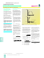
■ Power modules, current reduction curves
Current reduction
dependent on the inverter
clock frequency
X1 = Current reduction factor,
current reduction from the inverter clock frequency f0 of the
power transistors (refer to the
technical data).
(100 % – X 1) ⋅ (fT – f0 )
8 kHz – f0
Ambient temperature up to 40 °C
100 %
X = the reduction factor
obtained [in %]
for In, IS6, Imax.
fT = selected inverter clock
frequency
= X · Inf0/100 %
InfT
Is6fT = X · Is6f0/100 %
Imax.fT = X · Imax.f0/100 %
X1
GMC-5023
X = 100 % –
I
In
f1 [kHz]
0%
f0
0
®
®
®
2
8
For detailed information
see section 6
Fig. 2/10
Current reduction as a
function of the installation
altitude
XH
100%
GMC-5134a
80%
I n altitude
60%
= X H I n 1000 m
/100%
= X H I s6 1000 m /100%
I max. altitude = X H I max. 1000 m /100%
I S6 altitude
40%
20%
0%
0
3281
1000
6562
2000
9843
3000
13124
4000
16405 Installation altitude ft (m)
5000
For detailed information
see section 6
Fig. 2/11
■ Braking units and braking resistors
External pulsed resistor
Rated voltage
DC link voltage
600 V/625 V/680 V DC
Service thresholds
Upper threshold
644 V/670 V/744 V DC
Lower threshold
618 V/640 V/718 V DC
Internal pulse resistor
Load class
Continuous power PD
0.3 kW
1.5 kW
0.3 kW
0.2 kW
Short-time power rating Pmax
25 kW
25 kW
10 kW
Cycle time
10 s
Overload duration
0.6 s
0.12 s; 0.2 s
Peak rating Emax
7.5 kWs; 180 kWs
7.5 kWs; 13.5 kWs
Siemens General Motion Control Catalog Part 3 · 2001
2/5
SIMODRIVE 611 universal
Technical Data
General technical data
SIMODRIVE POSMO A
SIMODRIVE
611 universal
■ HF commutating reactors, supply voltage 400/480 V 3-phase AC
Supply voltage
400 V 3-phase AC ± 10 % to 480 V 3-phase AC + 6 % – 10 %
Frequency
50/60 Hz ± 10 %
Degree of protection
IP 00 in accordance with DIN EN 60 529 (IEC 60 529)
Humidity classification according to
DIN EN 60 721-3-3
Cl. 3K5, condensation and icing excluded.
Low air temperature: +32 °F (0 °C)
Permissible ambient temperature
• Operation
• Storage and transport
–13 °F to +104 °F (–25 °C to +40 °C), up to +131 °F (+55 °C) with derating
–13 °F to +176 °F (–25 °C to +80 °C)
■ Mains filters
2
Supply voltage1)
400 V 3-phase AC ± 10 % or 415 V 3-phase AC ± 10 % (TN network)
Frequency
50/60 Hz ± 10 %
Degree of protection
IP 20 according to DIN EN 60 529 (IEC 60 529)
Humidity classification according to
DIN EN 60 721-3-3
Cl. 3K5, condensation and icing excluded.
Low air temperature: +32 °F (0 °C)
Permissible ambient temperature
• Operation
• Storage and transport
Interference suppression
+32 °F to +104 °F (0 °C to +40 °C), up to +131 °F (+55 °C)
with 0.6 x Prated of the O/I or I/RF module
–13 °F to +158 °F (–25 °C to +70 °C)
According to EN 55 011, conducted limit class A
if configured according to the Planning Guide
■ Monitoring module
Rated supply voltage
400 V 3-phase AC – 10 % to 480 V 3-phase AC
+ 6 % 50 Hz to 60 Hz ± 10 % or 490 V to 680 V DC
Power loss
70 W
■ Overvoltage limiter module
Maximum energy absorption
100 joule
1) If a mains filter required, direct connection to
480 V 3-phase AC input is not possible.
A separate isolation transformer is required.
Further, output of the system will be reduced to
approx. 350 V A. Take care to select the motor
based on this rating.
2/6
Siemens General Motion Control Catalog Part 3 · 2001
SIMODRIVE POSMO A
Technical Data
SIMODRIVE
POSMO A
General technical data
SIMODRIVE POSMO A
■ Motor Data
Supply voltage
24 V DC ± 20 %
Rated power and voltage are reduced when the power supply voltage drops below 24 V.
Motor type
Permanent-magnet brushless servomotor (brushless DC: BLDC)
Degree of Protection
(to DIN EN 60 529)
IP 54 (TENV)
IP 40 at the motor shaft and planetary gearbox shaft. The shaft may not run in an oil bath.
If necessary, grease lubrication must be provided.
Cooling
Non-ventilated (free convection)
Overload
• S3 15 %, 60 s
• Monitoring
2 x rated torque for 15 s within 60 s
I2t limit
Position encoder (integrated)
Incremental
Resolution 816 ppr
Rated motor speed
3000 rpm
Rated motor torque
1.6 lbf-in (0.18 Nm)
Rated motor current
4.5 A
Motor efficiency
65 %
Motor moment of inertia
0.531 x 10⁻³ lb-in-s2 (0.06 x 10⁻³ kgm2)
Permissible ambient temperature
(to DIN EN 60 721,
Part 3-3 class 3K5)
• Operating
• Extended operating
• Transport and storage
+32 °F to 113 °F (0 °C to 45 °C)
+32 °F to 149 °F (0 °C to 65 °C)
(with continuous current reduction)
–40 °F to 158 °F (–40 °C to 70 °C) (to DIN EN 60 721, Parts 3-1 and 3-2, classes 2K4 and 1K4)
Installation altitude
Gearbox lifetime
3300 ft (1000 m) above sea level
4900 ft (1500 m)
6600 ft (2000 m)
9900 ft (3000 m)
14800 ft (4500 m)
19700 ft (6000 m)
2
Derating factor 0.91
Derating factor 0.88
Derating factor 0.83
Derating factor 0.75
Derating factor 0.68
A generally valid statement regarding the gearbox lifetime cannot be made due to the diversity
of applications possibilities and the resulting load types as well as the extremely wide range of ambient
conditions.
Caution!
If the worm gear must be rotated due to the mechanical configuration, the retaining bolts must be
subsequently tightened with a torque of 1.5 lbf-ft (2 Nm) and secured using Loctite 274. Warranty is not
provided for damage if incorrectly handled.
Vibration stressing in operation
(to IEC 68-2-6, DIN EN 60 721,
Parts 3-0 and 3-3, class 3M6)
Frequency range 2 … 9 Hz with constant deflection = 0.276 in (7 mm)
Frequency range 9 … 200 Hz with constant acceleration = 65.6 ft/s2 (20 m/s2)
Shock stressing in operation
(to DIN EN 60 721
Parts 3-0 and 3-3, class 3M8)
• Peak acceleration
• Shock duration
max. 250 ms2
6 ms
Vibration and shock stressing
during transport
To DIN EN 60 721, Part 3-3, class 2M2
(data is valid for components in their original packing)
List of materials
• Electronic housing GD-ALSi12 (CU) (die cast aluminum)
• Motor bearing end-shields GD-ZNAL4 (zinc die cast)
• Motor shaft 100CR6 DIN 17 350
• Gearbox end-shield GD-ZNAL4 (zinc die cast)
• Gearbox shaft X40CR13 DIN 17 440
• Gearbox flange X12CR MO S17 DIN 17 440
• Gearbox hollow wheel (housing) 16MN CR5 BKW; galvanized surface
Stressing as a result of cooling
and lubrication medium
The stressing of seals was tested using various cooling and lubricating mediums.
The result of the tests of compatible mediums can be requested when required.
However, incompatibilities cannot be generally excluded due to the continually changing chemical
composition for cooling and lubricating mediums.
Siemens General Motion Control Catalog Part 3 · 2001
2/7
SIMODRIVE POSMO A
Technical Data
General technical data
SIMODRIVE POSMO A
SIMODRIVE
POSMO A
Overload characteristic
Derating factors
A
200
9
150
4.5
100
No load period = Motor is switched off
0
10
20
30
40
50
60 s
t
0
Temperature
0
10
20
30
40
50
60 °C
4
3.5
3
2.5
2
1.5
GMC-5003
1
0.5
0
32
42
52
62
72
82
92
102 112 122 132 142 °F
Temperature
Fig. 2/14
Current reduction as a function of ambient temperature
2/8
3000
4000
0
3300
6600
9900
13200
Altitude
5000 6000 m
1
0.9
0.8
0.7
0.4
Fig. 2/13
Derating factor as a function of altitude
Reduction curves
IS1
2000
0.5
Fig. 2/12
Overload capabilities POSMO A S3 15 %, 1 min
5
A
4.5
1000
GMC-5137
2
0
0.6
50
0
1.1
Derating factor
Rated current
%
Current
GMC-5004
250
Siemens General Motion Control Catalog Part 3 · 2001
16500 19800 ft
Altitude
SIMODRIVE POSMO A
Technical Data
SIMODRIVE
POSMO A
SITOP 24 V Power supply standard type
Power management module (PMM)
■ SITOP 24 V Power supply standard type
AC single-phase units
AC three-phase units
Rated input voltage
1 ~ 120/230 V AC ± 15 %
3 ~ 400 to 500 V ± 10 %
Rated line frequency
50/60 Hz; 47 to 63 Hz
Overload monitoring
I2t limit monitoring
Integral input fuse
Yes
None
Supply cable protection
Recommended
Required
Output
Regulated floating direct voltage
Rated output voltage
24 V DC ± 3 %
Parallel connection to increase power
Yes (only for ambient temperatures from 32 °F to 113 °F / 0 °C to 45 °C)
Output overvoltage protection
Yes to EN 60 950
Short circuit protection
Electronic shutdown, automatic restart
Approvals
UL/cuL (CSA), CE
Degree of protection
IP 20
Isolation primary/secondary
Yes, SELV output voltage Vout to EN 60 950
Protection class (IEC 536)
Class 1
Line harmonics limiting
EN 61 000-3-2
Spurious emission
EN 50 081-1, EN 55 022 Class B
Operating ambient temperature
+32 °F to +131 °F (0 °C to +55 °C) with natural convection
Transportation and storage temperature
–4 °F to +185 °F (–20 °C to +85 °C)
Humidity class
Climatic class 3K3 to EN 60 721
2
■ Power management module (PMM)
Rated input voltage
24 V DC
Operating voltage range
19.2 V DC to 28.8 V DC
Max. permissible continuous current via PMM
28 A at +104 °F (+40 °C) ambient temperature
Overload monitoring
I2t limit monitoring to protect pulse resistor
Type of relay
Monostable relay with alternating contact
Maximum relay switching voltage
150 V DC/125 V AC
Operating temperature
+32 °F to +131 °F (0 °C to +55 °C)
Storage and transport temperature
–13 °F to +185 °F (–25 °C to +85 °C)
Type of protection
IP 20 as per IEC 529
Siemens General Motion Control Catalog Part 3 · 2001
2/9
SIMODRIVE POSMO A
Technical Data
SIMODRIVE
POSMO A
Power cable
■ 6FX50 08-5FA00 power cable
Certifications
UL style No. 2570
Electrical resistance
IEC 228 / CEI 20-29 CL.5
Test voltage
2000 V AC
Rated voltage
600 V AC
Insulation resistance per kilometer (0.625 miles)
at +68 °F (+20 °C)
2
³ 100 MW
Storage temperature
+14 °F to +176 °F (–10 °C to +80 °C)
Operating temperature
+32 °F to +176 °F (0 °C to +80 °C)
Bending radius
15 x D
Outer sheath
PVD
■ 6ES71 94-1LY00-0AA0 and 6ES71 94-1LY10-0AA0 power cable
6ES71 94-1LY00-0AA0
6ES71 94-1LY10-0AA0
Other sheath
PVC
PUR
Outer sheath thickness
0.0315 in (0.8 mm)
Leads cross sections
1 x 2 x 0.65 mm2 + 3 x 1 x 0.75 mm2
Outside diameter
0.374 in ± 0.02 in (9.5 ± 0.5 mm)
Permissible minimum bending diameter
• Once-only bending
• Recurrent bending
³ 2.76 in (70 mm)
³ 5.51 in (140 mm)
Operating temperature
–22 °F to +140 °F (–30 °C to +60 °C)
Weight
Approx. 144.7 lb/mile (105 kg/km)
Electrical properties at 68 °F (20 °C)
• Conductor resistance
£ 26 W/km for 0.75 mm22
£ 84 W/km for 0.65 mm
³ 20 MW/km
• Insulation resistance
• Operating voltage (peak)
• Test voltage
35 V
500 V
Flame test
To VDE 0472, Part 804, test type B
Oil resistance
–
To VDE 0471, Part 804, test type B
Suitable for drum use
–
Yes
2/10
Siemens General Motion Control Catalog Part 3 · 2001
SIMODRIVE POSMO A
Technical Data
SIMODRIVE
POSMO A
Bus connectors
■ Bus connectors, technical specifications
6ES79 72-0BA50-0XA0
6ES79 72-0BB50-0XA0
6GK15 00-0FC00
2
Cable outlet
90° cable outlet
180° cable outlet
Transmission rate
9.6 Kbit/s … 12 Mbit/s
9.6 Kbit/s … 12 Mbit/s
Terminating resistor
Integrated resistor
combination to be enabled via slide switch
Isolation function:
With the resistor connected, the outgoing bus
is isolated.
Connected with insulation displacement techique
for FastConnect system
Integrated resistor
combination to be enabled via slide switch
Isolation function:
With the resistor connected, the outgoing bus
is isolated.
Connected with insulation displacement techique
for FastConnect system
9-pin sub-D female connector
4 insulation displacement terminals for all
FastConnect PROFIBUS cables
(except FC Process Cable)
9-pin sub-D female connector
4 insulation displacement terminals for all
FastConnect PROFIBUS cables
(except FC Process Cable)
Supply voltage (to be supplied by DTE)
4.75 to 5.25 V DC
4.75 to 5.25 V DC
Current consumption
Max. 5 mA
Max. 5 mA
Permissible ambient conditions
• Operating temperature
• Transportation/storage temperature
• Relative humidity
–13 °F to 176 °F (0 °C to +60 °C)
+32 °F to 140 °F (–25 °C to +80 °C)
Max. 75 % at 77 °F (+25 °C)
–13 °F to 176 °F (0 °C to +60 °C)
+32 °F to 140 °F (–25 °C to +80 °C)
Max. 75 % at 77 °F (+25 °C)
Construction
• Dimensions (W x H x D) in in (mm)
• Weight
2.86 x 0.63 x 1.34 (72.7 x 16 x 34)
approx. 0.11 lb (50 g)
0.59 x 2.24 x 1.54 (15 x 57 x 39)
approx. 0.22 lb (100 g)
PG female connector
0BA50: no; 0BB50: yes
no
Degree of protection
IP 20
IP 20
Interfaces
• PROFIBUS stations
• PROFIBUS LAN cable
Siemens General Motion Control Catalog Part 3 · 2001
2/11
SIMODRIVE POSMO A
Technical Data
SIMODRIVE
POSMO A
LAN cables for PROFIBUS
■ LAN cables1), technical specifications
PROFIBUS
FC standard cable
PROFIBUS
FC robust cable
PROFIBUS 2)3)
FC trailing cable
MHz
MHz
kHz
< 42 dB/km
< 22 dB/km
< 2.5 dB/km
< 42 dB/km
< 22 dB/km
< 2.5 dB/km
< 49 dB/km
< 25 dB/km
< 3 dB/km
Impedance
• at 9.6
kHz
• at 38.4
kHz
• at 3 to 20 MHz
270 ± 27 W
185 ± 18.5 W
150 ± 15 W
270 ± 27 W
185 ± 18.5 W
150 ± 15 W
270 ± 27 W
185 ± 18.5 W
150 ± 15 W
Shield resistance
£ 110 W/km
£ 9.5 W/km
£ 110 W/km
£ 9.5 W/km
£ 133 W/km
£ 14 W/km
Effective capacitance
at 1 kHz
approx. 28.5 nF/km
approx. 28.5 nF/km
approx. 28.5 nF/km
02YY (ST) CY
1 x 2 x 0.64/2.55150 KF 40 FR VI
02YSY (ST) C11Y
1 x 2 x 0.64/2.55150 KF 40 FRNC VI
02Y Y (ST) C11Y
1 x 2 x 0.64/2.55150 LI KF 40 FR petrol
Sheath
• Material
• Diameter
• Color
PVC
0.3/5 in ± 0.016 (8.0 ± 0.4 mm)
purple
PUR
0.3/5 in ± 0.016 (8.0 ± 0.4 mm)
purple
PUR
0.3/5 in ± 0.016 (8.0 ± 0.4 mm)
purple
Permissible ambient conditions
• Operating temperature
• Transportation/storage temperature
• Installation temperature
–40 °F to +140 °F (–40 °C to +60 °C)
–40 °F to +140 °F (–40 °C to +60 °C)
–40 °F to +140 °F (–40 °C to +60 °C)
–40 °F to +140 °F (–40 °C to +60 °C)
–40 °F to +140 °F (–40 °C to +60 °C)
–40 °F to +140 °F (–40 °C to +60 °C)
–40 °F to +140 °F (–40 °C to +60 °C)
–40 °F to +140 °F (–40 °C to +60 °C)
–40 °F to +140 °F (–40 °C to +60 °C)
Bending radii
• First & final bending
• Repeated bending
³ 2.95 in (³ 75 mm)
³ 5.91 in (³ 150 mm)
³ 2.95 in (³ 75 mm)
³ 5.91 in (³ 150 mm)
³ 1.575 in (³ 40 mm)
³ 2.362 in (³ 60 mm)
Permissible tensile load
22.5 lbf (100 N)
22.5 lbf (100 N)
22.5 lbf (100 N)
Weight
104.7 lb/mile (76 kg/km)
100.6 lb/mile (73 kg/km)
102 lb/mile (74 kg/km)
Free of halogen
no
no
no
Behavior in fire
flame-retardant
acc. to VDE 0472
T804
C test type
flame-retardant
acc. to VDE 0472
T804
B test type
flame-retardant
acc. to VDE 0472
T804
B test type
UL listing
yes
yes
yes
Resistance to mineral oils and
greases
conditionally resistant
good resistance
good resistance
UV resistance
no
no
yes
Attenuation
• at 16
• at 4
• at 9.6
2
Rated value
Loop resistance
Operating voltage (rms value)
Type of cable (standard code)
150 W
£ 100 V
1) Electrical characteristics at 20 °C,
tested according to DIN 47 250 Part 4 or
DIN VDE 0472.
2/12
150 W
£ 100 V
2) Trailing-type cables for the following requirements: min. of 4 million bending cycles at the
specified bending radius and a max. acceleration of 4 m/s2.
Siemens General Motion Control Catalog Part 3 · 2001
150 W
£ 100 V
3) Restricted segment lengths
(see the manual for PROFIBUS networks).
SIMODRIVE
611 universal
POSMO A
Selection and
Ordering Data
3/2
3/2
3/3
3/4
3/5
3/5
3/5
3/5
SIMODRIVE 611 universal
System components
Infeed modules
Power modules
Plug-in units
Overvoltage limiter
Monitoring module
Pulsed resistor module
External pulsed resistor
3/6
3/6
3/6
Software
2-tier configuration
Additional components
Software
3/7
3/8
3/8
3/9
Mechanical components
External cooling
Hose (pipe) cooling
Fan for internal and external cooling
Shield terminal plate
3/10
3/10
3/10
3/11
3/11
3/11
System components/Line side components
HF commutating reactors
Mains filters
Mains filters package
Demo unit
Start-up box
Training courses
3/13
SIMODRIVE POSMO A
Intelligent positioning motor
POSMO A 0.1 HP (75 W)
3/14
3/14
Cables and connectors
Power cable
PROFIBUS cables and connectors
3/15
3/15
3/16
Requirements
Power Management Module
Demonstration units
SITOP Power
Siemens General Motion Control Catalog Part 3 · 2001
3
3/1
SIMODRIVE 611 universal
Selection and Ordering Data
SIMODRIVE
611 universal
System components
■ Infeed modules
Unregulated control
with pulsed
resistor
Regulated Infeed14) Peak
control with power
infeed
regeneraS6 –40% power
tive feedback
Rated DC
link power
(S1)
Rated DC
link power
(S1)
HP
(kW)
HP
(kW)
Rated
supply
current
Peak
supply
current
Infeed module
Power loss Module
width
For dimension
drawing,
see Section 7
Weight
with fan/
without fan
HP
(kW)
HP
(kW)
A
A
Order No.
W
Feedback
power
continuous/
peak
in
(mm)
Fig. No.
lb
(kg)
kW
7/14
(14.3
(6.5)
0.2/104)11)
0.3/254)11)
Internal cooling
3
(6.54)
(5)
–
(8.8
(6.5)
(13.6
(10)
12.5
25
6SN11 46-1AB00-0BA1
–/2705)6)
(13.54)
(10)
–
(17.5
(13)
(34
(25)
24
60
6SN11 45-1AA01-0AA1
–/4506)
(3.9
(100)
7/14
(20.9
(9.5)
(38
(28)
–
(49
(36)
(68
(50)
65
116
6SN11 45-1AA00-0CA0
–/250
(7.9
(200)
7/14
(34.1
(15.5)
59
6SN11 45-1BA01-0BA1
–/320
(3.9
(100)
7/14
(23.1
(10.5)
16/3512)
(1.97
(50)
–10)
–
(22
(16)
(28.5
(21)
(47.6
(35)
27
–
(49
(36)
(64
(47)
(95.2
(70)
60.5
117.5
6SN11 45-1BA02-0CA1
–/585
(7.9
(200)
7/14
(34.1
(15.5)
36/7012)
–
(75
(55)
(96.5
(71)
92.5
153
6SN11 45-1BA01-0DA1
–/745
(11.8
(300)
7/14
(57.2
(26)
55/9112)
–
(109
(80)
(141
(104)
(178
(131)
134
220
6SN11 45-1BB00-0EA1
–/12807)
(11.8
(300)
7/15
(57.2
(26)
80/13112)
–
(160
(120)
(212
(156)
(238
(175)
202
294
6SN11 45-1BB00-0FA1
–/19507)
(11.8
(300)
7/15
(57.2
(26)
120/17512)
7/18
(14.3
(6.5)8)
0.2/104)11)
0.3/254)11)
(124
(91)
External cooling
(6.54)
(5)
–
(8.8
(6.5)
(13.6
(10)
12.5
25
6SN11 46-1AB00-0BA113) 270/–5)
(13.54)
(10)
–
(17.5
(13)
(34
(25)
24
60
6SN11 45-1AA01-0AA113) 119/331
(3.9
(100)
7/18
(20.9
(9.5)8)
(38
(28)
–
(49
(36)
(68
(50)
65
116
6SN11 46-1AB00-0CA013)
90/160
(7.9
(200)
7/18
(34.1
(15.5)8)
59
6SN11 46-1BB01-0BA113)
50/270
(3.9
(100)
7/18
(23.1
(10.5)8)
16/3512)
50/535
(7.9
(200)
7/24
(34.1
(15.5)8)
36/7012)
(1.97
(50)
–10)
–
(22
(16)
(28.5
(21)
(47.6
(35)
27
–
(49
(36)
(64
(47)
(95.2
(70)
60.5
117.5
6SN11 46-1BB02-0CA113)
–
(75
(55)
(96.5
(71)
92.5
153
6SN11 46-1BB00-0DA113) 115/630
(11.8
(300)2)
7/25
(57.2
(26)8)
55/9112)
–
(109
(80)
(141
(104)
(178
(131)
134
220
6SN11 46-1BB00-0EA113) 190/1090
(11.8
(300)3)
7/25
(57.2
(26)8)
80/13112)
–
(160
(120)
(212
(156)
(238
(175)
202
294
6SN11 46-1BB00-0FA113) 290/1660
(11.8
(300)3)
7/25
(63.8
(29)8)
120/17512)
153
6SN11 45-1BB00-0DA12)
115/630
(11.8
(300)3)
7/16
(57.2
(26)9)
55/9112)
(124
(91)
Hose (pipe) cooling
–
(75
(55)
(96.5
(71)
(124
(91)
92.5
–
(109
(80)
(141
(104)
(178
(131)
134
220
6SN11 45-1BB00-0EA12)
190/1090
(11.8
(300)3)
7/16
(57.2
(26)9)
80/13112)
–
(160
(120)
(212
(156)
(238
(175)
202
294
6SN11 45-1BB00-0FA12)
290/1660
(11.8
(300)3)
7/16
(63.8
(29)9)
120/17512)
1) For external cooling, the fan box is part of the
scope of supply of the mounting frame for the
11.8 in (300 mm) module width. The required
6SN11 62-0BA02-0AA1 built-on fan must be
ordered separately.
2) The mounting frame can be omitted if the
required openings for the module heat sinks are
made as specified in the Planning Guide in the
cabinet rear panel. The above-mentioned
mounting frame 6SN11 62-0BA04-0EA0 must be
used with modules that are 11.8 in (300 mm)
wide.
3) A built-on fan 6SN11 62-0BA02-0AA1 is required
for these 11.8 in (300 mm) modules for the internal cooling.
4) Housing suitable for drive groups with internal
and external cooling.
5) 109 HP/160 HP (80 kW/120 kW) I/RF (aka. I/R)
modules require an external control voltage for
the internal line contactor.
360 to 457 V AC 2-phase/45 Hz to 53 Hz;
400 V to 510 V AC 2-phase/57 Hz to 65 Hz.
6) Including the part of the internal pulsed resistor.
7) Built-on fan 6SN11 62-0BA02-0AA1 is needed.
3/2
Siemens General Motion Control Catalog Part 3 · 2001
8) Without built-in components.
9) Without hose cooling kit.
10) Max. connectable external pulsed resistor
2 x 2 HP/34 HP (1.5 kW/25 kW).
11) Performance of integrated pulsed resistor.
12) Regenerative feedback power.
13) Mounting frame for switching cabinet is
needed, see mechanical components.
14) Load duty cycle with pre-loading conditions
see section 6.
SIMODRIVE 611 universal
Selection and Ordering Data
SIMODRIVE
611 universal
System components
■ Power modules
Power modules for
1FT6/1FK6/1FN3 motors
1PH motors4)
Rated current Peak current Power8)
loss total/
internal/
external
Rated current Peak current Power8)
loss total/
internal/
external
A
A
A
W
A
W
Power module
Module
width
For dimension drawing, see
Section 7
Weight
Order No.
in (mm)
Fig. No.
lb (kg)
Internal cooling1)
1-axis Version
3
6
35/–/–
3
3
30/–/–
6SN11 23-1AA00-0HA1
1.97 (50)
7/14
14.3 (6.5)
5
10
50/–/–
5
8
40/–/–
6SN11 23-1AA00-0AA1
1.97 (50)
7/14
14.3 (6.5)
9
18
90/–/–
8
16
74/–/–
6SN11 23-1AA00-0BA1
1.97 (50)
7/14
14.3 (6.5)
18
36
190/–/–
24
32
260/–/–
6SN11 23-1AA00-0CA1
1.97 (50)
7/14
16.5 (7.5)
28
56
300/–/–
30
51
320/–/–
6SN11 23-1AA00-0DA1
3.9 (100)
7/14
20.9 (9.5)
45
76
460/–/–
6SN11 23-1AA00-0LA1
5.9 (150)
7/14
28.6 (13)
–
–
–
56
112
645/–/–
60
102
685/–/–
6SN11 23-1AA00-0EA1
5.9 (150)
7/14
28.6 (13)
70
140
730/–/–
85
127
850/–/–
6SN11 23-1AA01-0FA1
11.8 (300)
7/14
57.2 (26)6)
–
–
–
120
193
1290/–/–
6SN11 23-1AA00-0JA1
11.8 (300)
7/15
46.2 (21)6)
140
210
1910/–/–
200
257
2170/–/–
6SN11 23-1AA00-0KA1
11.8 (300)
7/15
52.8 (24)6)
2-axis Version
2x 3
2x6
70/–/–
2x3
2x8
6SN11 23-1AB00-0HA1
1.97 (50)
7/20
15.4 (7)
2x 5
2 x 10
100/–/–
2x5
2x8
6SN11 23-1AB00-0AA1
1.97 (50)
7/20
15.4 (7)
2x 9
2 x 18
180/–/–
2x8
2 x 16
6SN11 23-1AB00-0BA1
1.97 (50)
7/20
15.4 (7)
2 x 18
2 x 36
380/–/–
on request
6SN11 23-1AB00-0CA1
3.9 (100)
7/22
29.7 (13.5)
External cooling2)7)
1-axis Version
3
6
–/14/21
3
3
–/12/18
6SN11 24-1AA00-0HA1
1.97 (50)
7/19
14.3 (6.5)
5
10
–/19/31
5
8
–/16/24
6SN11 24-1AA00-0AA1
1.97 (50)
7/19
14.3 (6.5)
9
18
–/35/55
8
16
–/29/45
6SN11 24-1AA00-0BA1
1.97 (50)
7/19
14.3 (6.5)
18
36
–/65/125
24
32
–/89/171
6SN11 24-1AA00-0CA1
1.97 (50)
7/19
16.5 (7.5)
28
56
–/30/270
30
51
–/32/288
6SN11 24-1AA00-0DA1
3.9 (100)
7/21
20.9 (9.5)
–
–
45
76
–/19/441
6SN11 24-1AA00-0LA1
5.9 (150)
7/23
28.6 (13)
56
112
–/25/620
60
102
–/30/655
6SN11 24-1AA00-0EA1
5.9 (150)
7/23
28.6 (13)
70
140
–/90/640
85
127
–/100/750
6SN11 24-1AA01-0FA1
11.8 (300)
7/25
57.2 (26)6)
–
–
–
120
193
–/190/1100
6SN11 24-1AA00-0JA1
11.8 (300)
7/25
46.2 (21)6)
140
210
–/250/1660
200
257
–/325/1845
6SN11 24-1AA00-0KA1
11.8 (300)
7/25
52.8 (24)
2x 3
2x6
–/27/43
2x3
2x8
6SN11 24-1AB00-0HA1
1.97 (50)
7/20
15.4 (7)
2x 5
2 x 10
–/38/62
2x5
2x8
6SN11 24-1AB00-0AA1
1.97 (50)
7/20
15.4 (7)
2x 9
2 x 18
–/69/111
2x8
2 x 16
6SN11 24-1AB00-0BA1
1.97 (50)
7/20
15.4 (7)
2 x 18
2 x 36
–/130/250
on request
6SN11 24-1AB00-0CA1
3.9 (100)
7/22
29.7 (13.5)
–
2-axis Version
Hose (pipe) cooling3)
1-axis Version
140
730/–/–
85
127
460/–/–
6SN11 23-1AA02-0FA15)
11.8 (300)
7/16, 7/17
28.6 (13)6)
–
–
–
120
193
1230/–/–
6SN11 23-1AA00-0JA1
11.8 (300)
7/16, 7/17
46.2 (21)6)
140
210
1910/–/–
200
254
2710/–/–
6SN11 23-1AA00-0KA1
11.8 (300)
7/16, 7/17
52.8 (24)
70
1) Internal cooling
A built-on fan is required for the power modules
6SN11 23-1AA00-0JA1 and ...-0KA1;
Order No.: 6SN11 62-0BA02-0AA1.
2) External cooling
The fan box is part of the scope of supply of the
mounting frame for the 11.820 in (300 mm) module width for external cooling. The corresponding built-on fan must be ordered separately;
Order No.: 6SN11 62-0BA02-0AA1.
3) Hose cooling
A hose cooling assembly kit with fan, hose, flanges and filter mat is required for each module.
Order No. for the hose cooling assembly kit:
6SN11 62-0BA03-0AA1.
4) Also for standard ILA induction motors only.
5) For hose cooling in 2-tier installations (permissible only for 75 HP (35 kW) I/RF (aka. I/R) modules and 85 A induction motors):
Hose connection kit 2-tier installation;
Order No.: 6SN11 61-0BA03-0CA1.
6) Without mounting and hose cooling components.
7) Mounting frame for switching cabinet is needed,
see mechanical components.
8) Total:
power loss from the module as a whole.
Internal: residual power loss in the switching
cabinet.
External: Power loss dissipated directly to
atmosphere.
The details apply to the corresponding rated
pulse frequency of the inverters.
Siemens General Motion Control Catalog Part 3 · 2001
3/3
3
SIMODRIVE 611 universal
Selection and Ordering Data
SIMODRIVE
611 universal
System components
■ Plug-in units
Designation
Order No.
Weight,
approx.
lb
(kg)
Dimensions
WxHxD
in x in x in
(mm x mm x mm)
Closed loop control plug-in unit with analog speed setpoint interface
1-axis version
2-axis version
Resolver, speed/torque setpoint
6SN11 18-0NJ00-0AA1
(2
(0.91)
1.772 x 12.265 x 4.724
(4.5 x 31 x 12)
Resolver, speed/torque setpoint,
positioning
6SN11 18-1NJ00-0AA1
(2
(0.91)
1.772 x 12.265 x 4.724
(4.5 x 31 x 12)
Resolver, speed/torque setpoint
6SN11 18-0NK00-0AA1
(2
(0.91)
1.772 x 12.265 x 4.724
(4.5 x 31 x 12)
Resolver, speed/torque setpoint,
positioning
6SN11 18-1NK00-0AA1
(2
(0.91)
1.772 x 12.265 x 4.724
(4.5 x 31 x 12)
sin/cos 1 Vpp/absolute encoder,
speed/torque setpoint
6SN11 18-0NH00-0AA1
(2
(0.91)
1.772 x 12.265 x 4.724
(4.5 x 31 x 12)
sin/cos 1 Vpp/absolute encoder,
speed/torque setpoint, positioning
6SN11 18-1NH00-0AA1
(2
(0.91)
1.772 x 12.265 x 4.724
(4.5 x 31 x 12)
Option modules for the plug-in unit
3
Terminal module for axis A
8 digital inputs/8 digital outputs,
24 V/500 mA (max.), electrically
isolated, parameterizable
6SN11 14-0NA00-0AA0
(0.25
(0.11)
0.984 x 2.362 x 4.724
(2.5 x 6 x 12)
PROFIBUS-DP
Standard slave for up to two axes
for cyclical and acyclical (V1) data
exchange up to 12 Mbaud
6SN11 14-0NB00-0AA1
(0.25
(0.11)
0.984 x 2.362 x 4.724
(2.5 x 6 x 12)
Motion control with
PROFIBUS-DP3
Synchronous standard slave for up
to two axes for cyclical and acyclical
(V1) data exchange up to 12 Mbaud
6SN11 14-0NB01-0AA0
(0.25
(0.11)
0.984 x 2.362 x 4.724
(2.5 x 6 x 12)
Note:
Shield terminal plates are required to fit shields to the encoder cables
(see mechanical components).
3/4
Siemens General Motion Control Catalog Part 3 · 2001
SIMODRIVE 611 universal
Selection and Ordering Data
SIMODRIVE
611 universal
System components
■ Overvoltage limiter
Designation
Overvoltage limiter
module
For mains infeed modules
above 13.6 HP
(10 kW)
for SIMODRIVE 611
Order No.
Weight
approx.
lb
(kg)
Dimensions
WxHxD
in x in x in
(mm x mm x mm)
6SN11 11-0AB00-0AA0
0.66
(0.3)
2.758 x 2.994 x 12.80
(70 x 76 x 325)
Note:
• With the overvoltage module the infeed module has a max. module depth of 12.805 in (325 mm).
• For UL compliance a overvoltage limiter module must be used.
• In the 6.8 HP (5 kW) O/I (aka. U/E) module an appropriate protective circuit is integrated.
■ Monitoring module
Designation
Monitoring module
Order No.
Power loss
Complete with 6SN11 12-1AC01-0AA1 70 W
all termination
and connection
elements suitable for internal
and external
cooling
Rated supply voltage
Weight
approx.
lb
(kg)
Module width
400 V AC 3-phase –10% to
480 V AC 3-phase +6%
50 Hz to 60 Hz ±10%
or
490 V to 680 V DC
11
(5)
1.97
(50)
Rated supply
voltage
Weight
approx.
lb
(kg)
Module width
in
(mm)
3
■ Pulsed resistor module
Designation
Pulsed resistor module
Order No.
Complete with 6SN11 13-1AB01-0BA1
all termination
and connection
elements
Power loss
Loaddependent
15 W to
max. 315 W
600 V/625 V/
680 V DC
Continuous
rating/
peak rating
• With internal 11
pulsed resis- (5)
tor 0.3 /25 kW
• With external
pulsed resistor 1.5/25 kW
in
(mm)
1.97
(50)
■ External pulsed resistor
Designation
Braking power
Order No.
Degree of
protection
Weight
approx.
lb
(kg)
Dimensions
WxHxD
in x in x in
(mm x mm x mm)
External pulsed resistor 1.5 kW/25 kW
6SN11 13-1AA00-0CA0 IP 20
12.375
(5.6)
7.604 x 6.154 x 9.456
(193 x 410 x 240)
0.3 kW/25 kW
only for 28 kW
O/I module
6SN11 13-1AA00-0DA0 IP 20
7.5
(3.4)
3.29 x 11.032 x 2.147
(83.5 x 280 x 54.5)
Siemens General Motion Control Catalog Part 3 · 2001
3/5
SIMODRIVE 611 universal
Selection and Ordering Data
SIMODRIVE
611 universal
System components · Software
■ 2-tier configuration
$ Adapter terminal
% Unit bus cable
1
GMC-5145
2
1
Fig. 3/1
2-tier configuration
3
Designation
Adapter terminals for DC link
connection
(for 2-tier configuration)
Unit bus cable
(for 2-tier configuration)
Order No.
• Package with two doubleterminals 50 mm2 for modules
1.970 in (50 mm) to 7.880 in
(200 mm) wide
6SN11 61-1AA01-0BA0
• Package with two doubleterminals 95 mm2 for module
11.820 in (300 mm) wide
6SN11 61-1AA01-0AA0
Length: 4 ft 11 in (1.5 m)
6SN11 61-1AA00-0AA1
■ Additional components
Designation
Shielded contacting clip
for electronics cables
Quantity: 10
Order No.
Grid
in
(mm)
6SN11 62-0FA00-0AA0
–
Note:
The shielded contacting clips for the electronics cables can be installed at the threaded bushes on the power and infeed modules
above the closed-loop control plug-in units
Female coding elements
for plug side (socket)
Quantity: 100
6FC9 348-7BA
0.197
(5)
Male coding elements
for pin side
Quantity: 100
6FC9 348-7BB
0.197
(5)
Note:
The plug-in terminals on the front panel of the modules can be coded by freely pluggable male coding elements on the pin side and
corresponding female coding elements on the plug side (socket).
The male and female coding elements are necessary only if the connectors are to be individually coded. The function of the plug-in terminals is not restricted if coding elements are not used.
■ Software
Designation
3/6
Order No.
SimoCom-U/611 universal
toolbox
Parameterization, start-up and
test tool in English, German,
French, Italian and Spanish on
CD-ROM
DRMS 02055
Drive ES Basic
Planning program embedded
in STEP 7
6SW17 00-0JA00-0AA0
Drive ES SIMATIC
Programming block for STEP 7
6SW17 00-0JC00-0AA0
Siemens General Motion Control Catalog Part 3 · 2001
SIMODRIVE 611 universal
Selection and Ordering Data
SIMODRIVE
611 universal
Mechanical components
■ External cooling
$ Switching cabinet (untreated
metal surface)
% Mounting frames sealed against
each other an against the back of
the switching cabinet (e.g. with
Terostat-9 from Teroson company). The sealing agent should
be applied continuously such that
the degree of protection IP 51 is
satisfied.
& Mounting frame
1
GMC-5144
2
3
Fig. 3/2
Mounting frame
Designation
Mounting frame for
switching cabinet installation of an infeed module
for external cooling
Size
infeed module
Size
power module
Infeed/power module
Mounting frame/
blanking plate
Width
1FT6/1FK6/1FN3
motors
1PH
motors
Order No.
in
(mm)
–
–
6SN11 46-1AB00-0BA1
6SN11 62-0BA04-0JA0
–
13.5 HP (10 kW) O/I –
–
6SN11 45-1AA01-0AA1
6SN11 62-0BA04-0HA1
–
38 HP (28 kW) O/I
–
–
6SN11 46-1AB00-0CA0
6SN11 62-0BA04-0DA1
–
22 HP (16 kW) I/R
–
–
6SN11 46-1BB01-0BA1
6SN11 62-0BA04-0BA1
–
49 HP (36 kW) I/R
–
–
6SN11 46-1BB02-0CA1
6SN11 62-0BA04-0DA1
–
75 HP (55 kW) I/R
–
–
6SN11 46-1BB00-0DA1
6SN11 62-0BA04-0EA0
–
109 HP (80 kW) I/R
–
–
6SN11 46-1BB00-0EA1
6SN11 62-0BA04-0EA0
–
160 HP (120 kW) I/R
–
–
6SN11 46-1BB00-0FA1
6SN11 62-0BA04-0EA0
–
6.5 HP (5 kW) O/I
Note:
The mounting frame can be omitted if the required openings for
the module heat sinks are made as specified in chapter 6 in the
cabinet rear panel. The above-mentioned mounting frame
6SN11 62-0BA04-0EA0 must be used with modules that are
11.8 in (300 mm) wide.
Mounting frame for
–
switching cabinet installa- –
tion of a power module
–
for external cooling
–
–
–
3/
6A
3/
3A
6SN11 24-1AA00-0HA1
6SN11 62-0BA04-0AA1
–
5/ 10 A
5/
8A
6SN11 24-1AA00-0AA1
6SN11 62-0BA04-0AA1
–
9/ 18 A
8/ 16 A
6SN11 24-1AA00-0BA1
6SN11 62-0BA04-0AA1
–
18/ 36 A
24/ 32 A
6SN11 24-1AA00-0CA1
6SN11 62-0BA04-0FA1
–
28/ 56 A
30/ 51 A
6SN11 24-1AA00-0DA1
6SN11 62-0BA04-0BA1
–
45/ 76 A
6SN11 24-1AA00-0LA1
6SN11 62-0BA04-0CA1
–
–
–
56/112 A
60/102 A
6SN11 24-1AA00-0EA1
6SN11 62-0BA04-0CA1
–
–
70/140 A
85/127 A
6SN11 24-1AA01-0FA1
6SN11 62-0BA04-0EA0
–
–
–
120/193 A
6SN11 24-1AA00-0JA1
6SN11 62-0BA04-0EA0
–
–
140/210 A
200/257 A
6SN11 24-1AA00-0KA1
6SN11 62-0BA04-0EA0
–
–
2 x 3/ 6 A
2 x 3/ 8 A
6SN11 24-1AB00-0HA1
6SN11 62-0BA04-0AA1
–
–
2 x 5/10 A
2 x 5/ 8 A
6SN11 24-1AB00-0AA1
6SN11 62-0BA04-0AA1
–
–
2 x 9/18 A
2 x 8/16 A
6SN11 24-1AB00-0BA1
6SN11 62-0BA04-0AA1
–
–
2 x 18/36 A
on request
6SN11 24-1AB00-0CA1
6SN11 62-0BA04-0GA1 –
–
6SN11 62-0BA04-0JA0
Note:
The mounting frame can be omitted if the openings required for
the modules are made as specified in chapter 6 in the cabinet
rear panel. A blanking plate (width 1.970 in [50 mm]) can be
supplied to cover the prepared opening:
Order No.: 6SN11 62-0BA04-0JA0.
The above-mentioned mounting frame must be used with modules that are 11.820 in (300 mm) wide.
Blanking plate for mounting –
the module and covering the
prepared opening for the
external cooling
–
–
Siemens General Motion Control Catalog Part 3 · 2001
1.97
(50)
3/7
3
SIMODRIVE 611 universal
Selection and Ordering Data
SIMODRIVE
611 universal
Mechanical components
■ Hose (pipe) cooling
Package 1
Package 2
I/RF
75/97 HP
55/71 kW
3
GMC-5143
GMC-5142
COD(MSD)
85/110 A
Fig. 3/3
Hose (pipe) cooling package 1 and 2.
Without infeed and power modules!
Designation
Order No.
Hose cooling packages
• Package 1
6SN11 62-0BA03-0AA1
for single module consisting of
2 x module connection flange 6 ft 7 in
(2000 mm) hose 1 x cabinet connection
flange
1 x radial fan with cabinet connection flange
360 V to 457 V 3-phase AC 47.5 Hz to 62.5 Hz
Connection current: 1 A to 1.2 A
• Package 2
for 2-tier configuration of 75 HP (55 kW) I/RF
and LT 85 A consisting of
4 x module connection flange 6 ft 7 in
(2000 mm) hose
1 x cabinet connection flange
1 x radial fan like Package 1
3/8
Siemens General Motion Control Catalog Part 3 · 2001
6SN11 62-0BA03-0CA1
Note:
A 2-tier installation is permissible for the 75 HP
(55 kW) I/RF module in combination with the
85 A power module. A hose connection assembly kit 6SN11 62-0BA03-0CA1 can be supplied
for this purpose.
SIMODRIVE 611 universal
Selection and Ordering Data
SIMODRIVE
611 universal
Mechanical components
■ Fan for internal and external cooling
Designation
Built-on fan
Radial blower for internal and
external cooling
Order No.
Degree of
protection
Rated supply
voltage
Connection
current
6SN11 62-0BA02-0AA1
IP 44
360 V to 510 V 0.2 to 0.3 A
3-phase AC
45 Hz to 65 Hz
Note:
A built-on fan 6SN11 62-0BA02-0AA1 is required for several 11.820 in (300 mm) modules
for the internal cooling (see power and infeed
modules in this chapter). For external cooling,
the fan box is part of the scope of supply of the
mounting frame for the 11.820 in (300 mm)
module width.
The required 6SN11 62-0BA02-0AA1 built-on
fan must be ordered separately.
■ Shield terminal plate
Designation
Shield terminal plate
Order No.
Module width
in
(mm)
For O/I (aka. U/E) module 6.5 HP
(5 kW), monitoring module and pulsed
resistor module
6SN11 62-0EB00-0AA0
1.97
(50)
For O/I (aka. U/E) module 13.5 HP
(10 kW)
6SN11 62-0EB00-0BA0
3.94
(100)
6SN11 62-0EA00-0AA0
1.97
(50)
6SN11 62-0EA00-0BA0
3.94
(100)
6SN11 62-0EA00-0CA0
5.91
(150)
6SN11 62-0EA00-0JA0
7.88
(200)
6SN11 62-0EA00-0DA0
11.82
(300)
6SN11 62-0EB00-0AA0
1.97
(50)
6SN11 62-0EB00-0BA0
3.94
(100)
6SN11 62-0EB00-0CA0
5.91
(150)
6SN11 62-0EB00-0JA0
7.88
(200)
6SN11 62-0EB00-0DA0
11.82
(300)
6SN11 62-0EA00-0KA0
11.82
(300)
3
For O/I (aka. U/E) module 38 HP
(28 kW), I/RF (aka. I/R) modules and
power modules with:
• Internal cooling
• External cooling
For modules with hose cooling or
internal cooling with built-on fan
Thermally conductive cover
6SN11 62-0BA01-0AA0
Note:
Unregulated control infeed modules are available for low outputs. These modules up to 13.5 HP (10 kW) contain the commutation reactor and a pulsed resistor which converts the braking energy of the drive modules into heat. With
maximum capacity utilization of the pulsed resistor (>200 W), a thermally conductive cover must be used in order to keep the heat away from the modules
located above.
Siemens General Motion Control Catalog Part 3 · 2001
3/9
SIMODRIVE 611 universal
Selection and Ordering Data
System components
Line side components
SIMODRIVE
611 universal
■ HF commutating reactors, supply voltage 400/480 V 3-phase AC
Assignment
to mains
infeed module
Order No.
HP
(kW)
Rated AC
Power loss
A
W
Max. conductor
cross-section,
primary/secondary side
Weight,
approx.
Dimensions
(W x H x D)
approx.
AWG
(mm2)
lb
(kg)
in
(mm)
(38
(28) (O/I)
6SN11 11-1AA00-0CA0
65
70
1
(50)
13.2
(6)
7.41 x 7.8 x 3.9
(190 x 200 x 100)
(22
(16) (I/RF)
6SN11 11-0AA00-0BA1
30
170
6
(16)
18.7
(8.5)
12.87 x 5.65 x 5.85
(330 x 145 x 150)
(49
(36) (I/RF)
6SN11 11-0AA00-0CA1
67
250
1
(50)
28.6
(13)
12.87 x 8.97 x 5.85
(330 x 230 x 150)
(75
(55) (I/RF)
6SN11 11-0AA00-0DA1 103
350
210
(70)
39.6
(18)
12.87 x 10.92 x 5.85
(330 x 280 x 150)
(109
(80) (I/RF)
6SN11 11-0AA00-0EA1
150
450
FL1)
88
(40)
14.82 x 9.75 x 6.63
(380 x 250 x 170)
(160
(120) (I/RF)
6SN11 11-0AA00-1FA0
225
590
FL1)
110
(50)
14.82 x 11.32 x 6.63
(380 x 290 x 170)
Order No.
Rated AC
Power loss
Max. conductor
cross-section,
primary/secondary side
Equipotential connection
(PE)
GND
A
W
■ Mains filters
3
Assignment
to mains
infeed module
HP
kW
AWG
(mm2)
Weight,
approx.
Dimensions
(W x H x D)
approx.
lb
(kg)
in
(mm)
(6.5
(5) (O/I)
6SN11 11-0AA01-1BA0
16
20
12
(4)
M 6, stud
8.36
(3.8)
6.08 x 7.52 x 3.15
(156 x 193 x 81)
(13.5
(10) (O/I)
6SN11 11-0AA01-1AA0
25
20
8
(10)
M 6, stud
12.54
(5.7)
6.08 x 10.95 x 3.54
(156 x 281 x 91)
(38
(28) (O/I)
6SN11 11-0AA01-1CA0
65
25
1
(50)
M 10, stud
27.5
(12.5)
6.66 x 10.17 x 5.49
(171 x 261 x 141)
(22
(16) (I/RF)
6SN11 11-0AA01-2BA0
30
70
8
(10)
M 5, stud
19.8
(9)
5.07 x 18.72 x 5.83
(130 x 480 x 149.5)
(49
(36) (I/RF)
6SN11 11-0AA01-2CA0
67
90
1
(50)
M 8, stud
35.2
(16)
5.07 x 18.72 x 9.53
(130 x 480 x 244.5)
(75
(55) (I/RF)
6SN11 11-0AA01-2DA0 103
110
1
(50)
M 8, stud
41.8
(19)
5.07 x 18.72 x 10.90
(130 x 480 x 279.5)
(109
(80) (I/RF)
6SN11 11-0AA01-2EA0
150
150
310
(95)
M 8, stud
48.4
(22)
7.8 x 18.72 x 10.90
(200 x 480 x 279.5)
(160
(120) (I/RF)
6SN11 11-0AA01-2FA0
225
200
FL1)
M 10, stud
70.4
(32)
11.7 x 18.72 x 10.90
(300 x 480 x 279.5)
■ Mains filters package
We mainly recommend ordering mains filter packages for
I/RF modules.
• Adapter sets are available to
adapt the mains filter packages to the assembly surface of
the filter modules. The mount-
ed depth juts out of the front
plane of the drive group by
0.788 in (20 mm) to 1.182 in
(30 mm).
Assignment
to I/RF infeed module
Mains filter package
Adapter set
HP
(kW)
Order No.
Order No.
(22
(16)
6SN11 11-0AA01-2BB0
6SN11 62-0GA00-0BA0
(49
(36)
6SN11 11-0AA01-2CB0
6SN11 62-0GA00-0CA0
(75
(55)
6SN11 11-0AA01-2DB0
6SN11 62-0GA00-0DA0
(109
(80)
6SN11 11-0AA01-2EB0
6SN11 62-0GA00-0EA0
(160
(120)
6SN11 11-0AA01-2FB0
6SN11 62-0GA00-0EA0
1) FL = Flat termination, 0.355 in (9 mm) hole
diameter.
3/10
Siemens General Motion Control Catalog Part 3 · 2001
SIMODRIVE 611 universal
Selection and Ordering Data
SIMODRIVE
611 universal
Demo unit and start-up box
■ Demo unit
Demo unit SIMODRIVE 611 universal:
• PROFIBUS-DP extension
board
• in aluminium enclosure
(with wheels)
• Two 1FK6 motors with
resolver
• O/I infeed module 6.5 HP
(5 kW)
• Start-up box
• 2-axis plug-in unit with
resolver feedback
• With transformer for 110 V
60 Hz power supply
Technical data
Designation
Value
Size (L x W x H)
22 in x 10.5 in x 31 in
(558 mm x 267 mm x 787 mm)
Weight
90 lb (41 kg)
Voltage supply
110 V 60 Hz, 1-phase
Ordering data
Designation
Order No.
Demo unit
6SN11 82-0TA00-2DP0-Z
3
Fig. 3/4
Demo unit
■ Start-up box
The start-up box is a support
device for starting up and servicing SIMODRIVE 611 universal controllers.
The start-up box can be connected to the plug-in unit. An
electronic circuit within the device is used for converting the
24 V DC auxiliary power supply
value of the converter into an
analog setpoint. The analog setpoint can be adjusted and is
displayed via a 5-digit LCD.
Performance characteristics of
the start-up box
• Analog setting of setpoints:
– coarse and fine setting by
means of two potentiometers
in the ratio 1 : 10
– polarity selector switch between normal and inverse
setpoint polarity
– potentiometer for analog offset value with autonomous
ON/OFF switch
– ON/OFF switch for setting
analog setpoints
• The analog setpoint is extensively decoupled and protected against pole-switching
within the operating voltage
range.
• The analog output signal of
the control terminal strip is
wired to 2 mm measuring
sockets in the start-up box.
• Six OFF switches for digital
enabling signals, with green
LED indicator lamps.
• Four red LEDs for displaying
digital output signals.
Fig. 3/5
Start-up box
Technical data
Designation
Value
Size (L x W x H)
6.9 in x 3.5 in x 1.8 in
(175 mm x 90 mm x 45 mm)
Voltage supply
24 V DC (via terminal – X101)
Voltage range, analog setpoint
0 V to 12.5 V/10 mA
Length of signal cable
4.3 ft (1.3 m)
Ordering data
Designation
Order No.
Start-up box
9AK1014-1AA00
■ Training courses
Contact Siemens Energy &
Automation Training at
www.aut.sea.siemens.com/
training.
Siemens General Motion Control Catalog Part 3 · 2001
3/11
SIMODRIVE POSMO A
Selection and Ordering Data
SIMODRIVE
POSMO A
Intelligent positioning motor
■ Scope of application
Intelligent positioning motor as
decentralized node on
PROFIBUS with following
features:
• Power section and complete
motion control in motor
• Link by means of communications and power bus
Typical applications:
• Positioning of formats or
stops
• Positioning of process variables (e.g. by means of motor valves)
3
Areas of application include
transfer lines and on production
machinery in the packaging,
wood, glass, printing and plastics industries, but also in medical diagnostics, such as positioning of adjustable operating
tables or X-ray equipment.
Other features
• The link by means of the communications and power bus
makes for a more straightforward machine infrastructure.
• Straightforward communications interface for incorporation into any PROFIBUS
environment. Utilizes the
straightforward PROFIBUS
services only.
• Two terminals (can be parameterized either as inputs or
outputs) for monitoring or control of external drive-related
signals, such as terminals or
limit switches.
• Comprehensive range of
examples makes for more
straightforward configuration
using STEP 7 in the SIMATIC
environment.
• Straightforward start-up by
adjustment of just a few factory-preset parameters.
Fig. 3/6
SIMODRIVE POSMO A
■ Mode of operation
■ Mounting
Compact mounting of converter
power section, motor control,
encoder, positioning control,
program memory and communications interface on the motor.
The motor can be equipped
with graduated planetary gearing from a modular gearbox.
• The removable terminal cover
with integral PROFIBUS address switch and terminating
resistor makes it possible to
disconnect the motor without
any interruption to communications.
1-axis positioning drive
The drive power is provided by
a supply voltage of 24 V DC,
conventional in mechanical engineering. PROFIBUS provides
the full range of travel functions,
such as:
Other functions:
• All connections are made
using standard cables.
• travel to
End position, with velocity
and adjustable acceleration
• backlash compensation
• travel around
One path and direction,
with velocity and adjustable
acceleration
The PROFIBUS makes for highspeed cyclical data transfer
between the slave and higherlevel PROFIBUS master, e.g.
a SIMATIC S7 central processing unit, a communications processor with master capability,
such as the CP 5412, or a communications module, such as the
CP 342-5, although standard
masters produced by other manufacturers can also be used.
• Local diagnostics by means of
LED (fault/ready), plus two
diagnostic socket connectors
(parameterizable analog outputs).
• travel with
Controlled speed
3/12
Siemens General Motion Control Catalog Part 3 · 2001
• jerk limitation
• on-the-fly block change
• actual value preset
• travel to fixed stop
• software limit switches
SIMODRIVE POSMO A
Selection and Ordering Data
SIMODRIVE
POSMO A
Intelligent positioning motor
■ POSMO A 0.1 HP (75 W) (In = 4.5 A, Pn = 0.084 HP/62 W)
Order No.
Rated
continuous
output
speed
Available
torque at
continuous
operation
rpm
lbf-in
(Nm)
6SN21 32-0AA11-1BA0 3300
Gearbox
type
Stage
number
Ratio
Gearbox
Efficiency
Permissible
continuous
gearbox
torque1)
Max.
available
overload
torque
Moment
of inertia
Weight,
approx.
lbf
(Nm)
lbf-in
(Nm)
lb-in2
(10–6 kgm2)
lb
(kg)
1.6
(0.18)
None
–
1
1
–
3.2
(0.36)
0.01708
(60)
6.84
(3.1)
Planetary
gearbox
PLG 52
(Play 1°)
1
4.5
0.85
10.6
(1.2)
12.4
(1.4)
0.01734
(60.9)
7.72
(3.5)
1
8
0.85
10.6
(1.2)
21.2
(2.4)
0.01734
(60.9)
7.72
(3.5)
6SN21 32-1BC11-1BA0
667
6.2
(0.7)
6SN21 32-1BF11-1BA0
413
10.6
(1.2)
6SN21 32-1CK11-1BA0
148
23.0
(2.6)
2
20.25
0.72
70.8
(8.0)
46.0
(5.2)
0.01734
(60.9)
8.2
(3.7)
6SN21 32-1CR11-1BA0
83
41.6
(4.7)
2
36
0.72
70.8
(8.0)
82.3
(9.3)
0.01734
(60.9)
8.2
(3.7)
6SN21 32-1CU11-1BA0
60
57.5
(6.5)
2
50
0.72
70.8
(8.0)
115
(13.0)
0.01734
(60.9)
8.2
(3.7)
6SN21 32-1DE11-1BA0
24
123
(13.9)
3
126.26
0.61
212
(24)
246
(27.8)
0.01734
(60.9)
8.6
(3.9)
6SN21 32-1DH11-1BA0
19
158
(17.8)
Planetary
gearbox
PLG 52
(Play 1.5°)
3
162
0.61
212
(24)
315
(35.6)
0.01734
(60.9)
8.9
(3.6)
6SN21 32-5KD11-1BA0
600
5.3
(0.6)
Worm gear
SG80
1
5
0.70
17.7
(2.0)
11.5
(1.3)
0.01751
(61.5)
7.72
(3.5)
6SN21 32-5KM11-1BA0
125
19.5
(2.2)
1
24
0.50
31.0
(3.5)
38.1
(4.3)
0.01751
(61.5)
7.72
(3.5)
1) The specified values are continuous torques.
The gearboxes may be briefly subject to higher
torques up to a maximum of twice the continuous torque without gearboxes being damaged.
The gearbox could be destroyed if this limit is
exceeded.
Siemens General Motion Control Catalog Part 3 · 2001
3/13
3
SIMODRIVE POSMO A
Selection and Ordering Data
SIMODRIVE
POSMO A
Cables and connectors
■ PROFIBUS LAN cables and connectors1)
SIMODRIVE POSMO A is controlled and parameterized via
PROFIBUS-DP. Stand-alone operation with up to 4 individually
selectable traversing blocks is
possible in case the communication is lost. However, to parameterize these traversing
blocks, a PROFIBUS connection incl. PROFIBUS cables and
connectors is needed.
3
Different types of PROFIBUS
cables are available for various
installation applications, e.g.
trailing cables, robust cables
etc. (for more information refer
to chapter 2 or the Siemens catalog IK 10 and the electronic
catalog CA01). Generally the
cables listed should be used.
Due to double-shielding these
cables are particularly suitable
for industrial environments subject to electromagnetic interference.
PROFIBUS FastConnect (FC) is
a system for fast and easy assembly of PROFIBUS copper
cables. The system comprises 3
compatible components:
Description
Order No.
Standard type, specially designed for
rapid assembly, two-wire, shielded,
sold by the meter;
consignment 3280 ft (1000 m) max.,
min. ordering quantity 65.6 ft (20 m)
PROFIBUS FC
Standard Cable
6XV18 30-0EH10
Preferred lengths
65.6 ft (20 m)
164 ft (50 m)
328 ft (100 m)
656 ft (200 m)
1640 ft (500 m)
6XV18 30-0EN20
6XV18 30-0EN50
6XV18 30-0ET10
6XV18 30-0ET20
6XV18 30-0ET50
PROFIBUS FC
Robust Cable
Two-wire, shielded, sold by the meter;
consignment 3280 ft (1000 m) max.,
min. ordering quantity 656 ft (20 m)
6XV18 30-0JH10
PROFIBUS FC
Trailing Cable
Two-wire, shielded, sold by the meter;
consignment 3281 ft (1000 m) max.,
min. ordering quantity 65.6 ft (20 m)
6XV18 30-3EH10
PROFIBUS
FastConnect
Stripping tool
6GK19 05-6AA00
Preset stripping tool for rapid stripping
of insulation from PROFIBUS Fast
Connect bus cables
Blade Cassettes
6GK19 05-6AB00
Spare blade cassettes for the
PROFIBUS FastConnect stripping
tool, 5 pieces
PROFIBUS
FastConnect bus
Connector RS 485 with 90° cable
outlet
With insulation displacement
technique
• without PG interface
• with PG interface2)
• FastConnect bus cables for
rapid installation
• FastConnect stripping tool
6ES79 72-0BA50-0XA0
6ES79 72-0BB50-0XA0
Connector RS 485 with 180°
cable outlet
• FastConnect bus connector
for PROFIBUS.
6GK15 00-0FC00
Plug 180
■ Power cable
The maximum connectable
cable cross-section to the
POSMO A 0.1 HP (75 W) is
AWG 12 (4 mm2). The cable
outside diameter must be between 0.315“ (8 mm) and 0.472“
(12 mm) to guarantee IP 55
degree of protection.
Shielding of the cable is recommended but not required. It can
be used any 2 lead that adhere
to the above mentioned limits.
The 6FX50 08-5FA00-1FA0
cable is recommended.
Designation
Current
capacity3)
Cross-section
Outside
cable
diameter
A
AWG
(mm2)
in
(mm)
Power cable
31
2 x AWG 12
(2 x 4 mm2)
0.42“
(10.7)
Power cable
PVC sheath
5
1 x 2 x AWG 19
(1 x 2 x 0.65 mm2)
3 x 1 x AWG 18
(3 x 1 x 0.75 mm2)
Power cable
Oil resistant
PUR sheath
5
1 x 2 x AWG 19
(1 x 2 x 0.65 mm2)
3 x 1 x AWG 18
(3 x 1 x 0.75 mm2)
Order No.
Weight
Length
lb/ft
(kg/m)
ft
(m)
0.118
(0.176)
164
(50)
0.374 ± 0.02 6ES71 94-1LY00-0AA0-Z4)
(9.5 ± 0.5)
0.071
(0.232)
Sold by
meter
0.374 ± 0.02 6ES71 94-1LY10-0AA0-Z4)
(9.5 ± 0.5)
0.071
(0.232)
Sold by
meter
6FX50 08-5FA00-1FA0
The power for the electronics is
supplied by the main power,
however if bus communications
and positioning sensing are to
remain active even with the load
power supply powered down,
an optional electronics power
supply can be connected
(24 V ±20%).
The power leads are routed
together with the PROFIBUS
Cable 6ES71 94-1LY00-0AA0 or
the oil resistant
6ES71 94-1LY10-0AA0.
1) PROFIBUS cables and connectors have been included
for your convenience, please order through your automation product channel.
2) D-Sub female connector on back of plug, allows to
piggyback second connector.
3/14
Siemens General Motion Control Catalog Part 3 · 2001
3) According to IEC 60 204-1 1997 corrigendum 1998,
at +104 °F (40 °C), installation condition C.
4) This automation product has been included for your
convenience, please order through your automation
product channels.
SIMODRIVE POSMO A
Selection and Ordering Data
SIMODRIVE
POSMO A
Power management components
and demo units
■ Power Management Module DC-PMM 24 V
The DC-PMM/24 V is installed
between one or more positioning motors (POSMO A) and the
load power supply, and is used
as feedback protection for the
latter. The PMM detects when
the positioning motor brakes
and uses an impulse resistor to
eliminate the feedback energy
from the motor.
An integrated I 2t monitor protects the impulse resistor against
thermal overloading, thus preventing damage to the resistor.
The relay contacts of the PMM
are used as signaling and monitoring contacts for the operating
states “Ready” and “Fault”.
Designation
Order No.
Power Management Module
(DC-PMM/24 V)
9AL21 37-1AA00-1AA0
Fig. 3/7
Power Management Module
3
■ Demonstration units
There is a single and a two-axis
demonstration unit for the
SIMODRIVE POSMO A available.
• Power outlet (US standard)
• 1-ph. 120 V
1-axis unit equipped with:
• Dimensions (W x H x D):
19.9 in x 15.8 in x 7.1 in
(500 mm x 400 mm x 180 mm)
• SIMODRIVE POSMO A
• Weight: 44.1 lb (20 kg)
• SITOP power supply
• Power Management Module
(PMM)
Designation
Order No.
Demonstration unit
1-axis unit
6SN28 92-0PG00-0AA0
Fig. 3/8
Demonstration unit, 1-axis
2-axis unit equipped with:
• 2 SIMODRIVE POSMO A
0.1 HP (75 W)
• All accessories
(cables, connectors)
• SIMATIC C7 626-DP PLC
• Software: S7-project with
integrated PROTOOL.
Different screen forms on C7
for parameter setting, MDI-input, jogging, referencing, display control word, status word
PROFIBUS.
• Preinstalled communication
program via PROTOOL on
C7.
• Dimensions (W x H x D):
13 in x 20 in x 17.3 in
(330 mm x 500 mm x 440 mm)
• Power outlet (US standard)
• Weight: 70.6 lb (32 kg)
• 2 SITOP power supply
• Power Management Module
(PMM)
• 1-ph. 120 V
Designation
Order No.
Demonstration unit
2-axis unit
6SN28 32-0CF00-0AA0
Fig. 3/9
Demonstration unit, 2-axis
Siemens General Motion Control Catalog Part 3 · 2001
3/15
SIMODRIVE POSMO A
Selection and Ordering Data
SIMODRIVE
POSMO A
Power components
■ SITOP power
The SITOP range of 24 V power
supplies has been optimized for
industrial applications and operates on the primary pulse
principle. The precise regulation of the output voltage makes
the devices suitable even for
connection to sensitive sensors.
DC/DC transformers with 600 V
inputs have been developed
specifically for connection to
converters with a DC link. The
drive energy can be used to provide a continued supply to 24 V
loads, even after a power failure;
appropriate safety measures
can therefore be implemented.
Technical features
• Integrated electronic shortcircuit protection
• Precise output voltage
• Safe electrical isolation (SELV
in accordance with EN 60 950)
• Low residual ripple
• Large input voltage range
• Comply with national and
international standards,
e.g. EMC in accordance with
EN 50 081-1/-2 and
EN 50 082-1/-2; UL/cUL
approval
• High utilization factor
• Straightforward assembly
10 A and 40 A DC USV modules
with external battery back-up are
available to provide protection
against lengthy power failures.
Version
Input
• No silicone release
Order No.
Voltage
Ue rated
Output
Voltage range
Voltage
Ua rated
Current
Ia rated
24 V DC/2 A; 5 A; 10 A; 20 A 1-phase CuUS1)
3
120 V/230 V AC
6EP13 31-2BA00
93 V – 132 V AC/
187 V – 264 V AC
24 V DC
±3%
2A
120 V/230 V AC
6EP13 33-2BA00
93 V – 132 V AC/
187 V – 264 V AC
24 V DC
±3%
5A
120 V/230 V AC
6EP13 34-2BA00
93 V – 132 V AC/
187 V – 264 V AC
24 V DC
±3%
10 A
120 V/230 V AC
6EP13 36-2BA00
93 V – 132 V AC/
187 V – 264 V AC
24 V DC
±1%
20 A
3-ph. 400 V – 500 V AC
6EP14 34-2BA00
3-ph. 360 V – 550 V AC
24 V DC
±3%
10 A
3-ph. 400 V – 500 V AC
6EP14 36-2BA00
3-ph. 360 V – 550 V AC
24 V DC
±3%
20 A
3-ph. 400 V – 500 V AC
6EP14 37-2BA00
3-ph. 360 V – 550 V AC
24 V DC
±3%
30 A
3-ph. 400 V – 500 V AC
6EP14 37-2BA10
3-ph. 360 V – 550 V AC
24 V DC
±3%
40 A
24 V DC/10 A; 20 A; 30 A; 40 A 3-phase CuUS1)
1) SITOP power supplies are part of the Siemens
Industrial Product Division in Batavia, Illinois,
please use your Products Division sales channel
to order this product.
3/16
Siemens General Motion Control Catalog Part 3 · 2001
SIMODRIVE
611 universal
POSMO A
Motor Selection
4/2
4/2
4/2
Efficiencies for synchronous
Siemens High Performance Motors
1FK6 Standard
1FT6 Water-cooled
1FT6 Self-cooled
For all other motor information see Catalog
General Motion Control Catalog Part 2
High Performance
Motors and Accessories
4
Siemens General Motion Control Catalog Part 3 · 2001
4/1
SIMODRIVE 611 universal and POSMO A
Motor Selection
Efficiencies for synchronous
Siemens High Performance Motors
SIMODRIVE
POSMO A
■ 1FK6 Standard
Motor
Winding / Speed
F
3000 rpm
K
6000 rpm
81 %
1FK6032- . . @ . .
–
1FK6040- . . @ . .
–
80 %
1FK6042- . . @ . .
86 %
–
1FK6060- . . @ . .
87 %
–
1FK6063- . . @ . .
89 %
–
1FK6080- . . @ . .
89 %
–
1FK6083- . . @ . .
90 %
–
1FK6100- . . @ . .
92 %
–
1FK6101- . . @ . .
92 %
–
1FK6103- . . @ . .
92 %
–
■ 1FT6 Water-cooled
Motor
4
Winding / Speed
B
1500 rpm
C
2000 rpm
F
3000 rpm
H
4500 rpm
K
6000 rpm
1FT6084- . S@ . .
–
–
91 %
91 %
91 %
1FT6086- . S@ . .
–
–
91 %
93 %
91 %
1FT6105- . S@ . .
92 %
93 %
94 %
–
–
1FT6108- . S@ . .
93 %
94 %
–
–
–
1FT6132- . S@ . .
93 %
94 %
95 %
–
–
1FT6134- . S@ . .
94 %
95 %
96 %
–
–
1FT6136- . S@ . .
94 %
95 %
–
–
–
B
1500 rpm
C
2000 rpm
F
3000 rpm
H
4500 rpm
K
6000 rpm
1FT6031- . A@ . .
–
–
–
–
87 %
1FT6034- . A@ . .
–
–
–
–
89 %
1FT6041- . A@ . .
–
–
85 %
–
88 %
1FT6044- . A@ . .
–
–
88 %
–
89 %
1FT6061- . A@ . .
–
82 %
86 %
88 %
87 %
1FT6062- . A@ . .
–
84 %
88 %
89 %
–
1FT6064- . A@ . .
–
87 %
89 %
89 %
–
1FT6081- . A@ . .
–
85 %
88 %
89 %
88 %
1FT6082- . A@ . .
–
87 %
90 %
90 %
88 %
1FT6084- . A@ . .
–
90 %
91 %
88 %
–
1FT6086- . A@ . .
–
90 %
91 %
90 %
–
1FT6102- . A@ . .
92 %
93 %
94 %
92 %
–
1FT6105- . A@ . .
93 %
94 %
94 %
–
–
1FT6108- . A@ . .
94 %
94 %
–
–
–
1FT6132- . A@ . .
94 %
95 %
94 %
–
–
1FT6134- . A@ . .
95 %
95 %
–
–
–
1FT6136- . A@ . .
95 %
95 %
–
–
–
■ 1FT6 Self-cooled
Motor
4/2
Winding / Speed
Siemens General Motion Control Catalog Part 3 · 2001
SIMODRIVE
611 universal
SIMODRIVE
611 universal
POSMO A
Documentation
5/2
5/2
5/2
5/2
Overview
General documentation
Manufacturer/Service documentation
Electronic documentation
Selection & ordering data
5
Siemens General Motion Control Catalog Part 3 · 2001
5/1
SIMODRIVE 611 universal and POSMO A
Documentation
SIMODRIVE
POSMO A
Overview
The documentation for the
units (infeed modules, power
modules, plug-in units), system
components and options is
supplied in German/English
with the products which have
been ordered.
SIMODRIVE documentation is
structured as follows:
• General documentation
• Manufacturer/Service documentation
• Electronic documentation
■ General documentation
These are used for selection
and preliminary engineering
information.
■ Manufacturer/Service
documentation
Catalog for High Performance
Motors and Accessories
This documentation addresses
machine OEMs and service
personnel who wish to use
“SIMODRIVE 611 universal”
with standard rotating motors in
the “speed/torque setpoint”
mode.
General Motion Control
Catalog Part 3 · 2001
Description of Functions
SIMODRIVE 611 universal
Catalog for SIMODRIVE 611 U
and SIMODRIVE POSMO A
This documentation addresses
machine OEMs and service
personnel who wish to use
“SIMODRIVE 611 universal”.
This function description provides detailed information on
the functionality of the
“SIMODRIVE 611 universal”
control board.
General Motion Control
Catalog Part 2 · 1999
SIMODRIVE
611 universal
■ Electronic documentation
General Motion Control CD
This CD, which is delivered with
each unit, contains:
• SimoComU V3.x a drives
configuration software for
SIMODRIVE 611 universal
• Function blocks to talk
PROFIBUS with a S7 master
for SIMODRIVE 611 universal
• All documentation in PDF files
• SIMOSIZE E and much more
Planning Guide
SIMODRIVE 611
This guide aids in the planning
of an application and gives you
detailed technical information
for the “SIMODRIVE 611 universal”.
User Manual POSMO A
This documentation addresses
machine OEMs and service
personnel who wish to use
“SIMODRIVE POSMO A”. This
function description provides
detailed information on the functionality of the “SIMODRIVE
POSMO A”.
■ Selection & ordering data
5
Documentation
Order no.
General documentation
General Motion Control Catalog Part 2 · 1999
DRSP-02062
General Motion Control Catalog Part 3 · 2001
DRSP-02080
Manufacturer/Service documentation
Short guide SIMODRIVE 611 universal (Brief description)
6SN11 97-0AB40-0BP2
Description of functions SIMODRIVE 611 universal
6SN11 97-0AB20-0BP2
Planning guide SIMODRIVE 611
6SN11 97-0AA00-0BP4
User Manual SIMODRIVE POSMO A, english
6SN21 97-0AA00-0BP1
Electronic documentation
General Motion Control CD
5/2
Siemens General Motion Control Catalog Part 3 · 2001
DRMS-02055
SIMODRIVE
611 universal
POSMO A
Engineering Information
6/2
6/25
6/27
6/30
6/32
6/33
6/34
6/36
6/37
6/39
6/40
6/42
6/46
6/63
6/65
6/67
6/68
6/73
6/74
6/76
6/78
6/82
6/83
6/84
SIMODRIVE 611 universal
Dimensioning of the power section and drive
Design SIMODRIVE
System-/Line side components
System components/Infeed and power modules
System components/Plug-in units
System components/Monitoring module
System components/Braking units and
braking resistors
System components/2-tier configuration
System components/Cooling systems
Dimensioning of the infeed module
Dimensioning of the power module
Wiring configuration overview
Unit design/Power and control terminals
Power and encoder cables
Line supply types
Electromagnetic compatibility (EMC)
Technology
SIMODRIVE POSMO A
System overview and requirements
General requirements
Connecting and wiring overview
Communication
SIMODRIVE POSMO A features
SIMODRIVE POSMO A functions
Current/Torque-Speed curves for
POSMO A 0.1 HP (75 W)
Siemens General Motion Control Catalog Part 3 · 2001
6
6/1
SIMODRIVE 611 universal
Engineering Information
SIMODRIVE
611 universal
Dimensioning of the power section and drive
■ Engineering instructions
Motion Control
• dynamic, i.e. have short risetimes and move to the desired position without overshoot
• high overload capability, i.e.
have a high acceleration reserve
• and must have a large control
range, i.e. high resolution for
exact positioning.
The planning notes below refer
to servo drives with 1FK6/1FT6
synchronous servomotors, with
1PH7/1PH4/1PL6 induction
servomotors or with 1FN3
linear motors.
Synchronous servomotors are
preferred where a compact
motor volume, low rotor inertia
and fast response levels are
important. With induction servomotors, high maximum
speeds are reached in the
field-weakened speed range.
They have a somewhat larger
motor volume.
6
The drives can be operated individually as single-axis drives
or together as multi-axis drives.
For connecting the drives to a
PLC, via PROFIBUS, a supplementary board is necessary.
Decentralized provision of positioning functions within the
Motion Control system is possible with the software or the
functions can be provided centrally using a higher level controller.
6/2
v
m
Guide
DA65-5074
Servo drives are mostly cycletype drives, i.e. drives which
perform particular sequences
of movement within a fixed
cycle of motion. These movements can be linear or rotational. In addition, the motion
sequence usually involves approaching a pre-defined position and all movements must
be carried out in the shortest
possible time. As a consequence, drives have to meet
specific requirements. They
must be
Motor
Gears
Spindle nut
Spindle
Fig. 6/1
Typical spindle drive
A typical planning sequence
The basis for planning is the
sketch and the description of
how the machine functions.
1. Clarification of the type of
drive, technical data and
other border conditions such
as technological functions
and integration into an automation system
2. Specification of the motion
curve
3. Calculation of the maximum
load torque, selection of the
gearbox
1. Clarification of the type of
drive, technical data and
other border conditions
The procedure for calculating
the load torque depends on the
type of drive. It may be a traction drive, a lifting drive or a
turntable drive. In the case of
linear motion, for example, power can be transmitted via a
toothed belt, a gear rack or a
spindle. Normally, a gearbox is
also needed for adapting the
motor speed and the motor
torque to the load conditions.
4. Selection of the motor
For this calculation, the following technical data must be
available:
5. Cooling methods
• The moving masses
6. Configuration of the drive
module
• The diameter of the drive
wheel or the diameter and
pitch of the spindle
7. Selection of the infeed
module
• Details of the frictional losses
8. Selection of the breaking unit
and braking resistor
• Mechanical efficiency
9. Selection of other components
• The maximum speed
Siemens General Motion Control Catalog Part 3 · 2001
• The travel distances
• The maximum acceleration
and the maximum deceleration
• The cycle time
• Accuracy levels for positioning
Further conditions are the integration into a system (PLC), the
technology to be used (central
or distributed) and the coupling
between the drives (e.g. with
PROFIBUS).
2. Specification of the motion
curve
The motion curve – namely the
v,t diagram when a linear drive
is being used – is determined
from the information relating to
travel distances, speed, acceleration, deceleration and the
cycle time. If multi-axis drives
are used, the interdependence
of the individual motion curves
must be taken into account. The
motion curve is also required for
thermally dimensioning the motor and selecting the braking
resistor. It should therefore represent the “worst-case
scenario” for the task.
SIMODRIVE 611 universal
Engineering Information
SIMODRIVE
611 universal
Information on the mechanical
factors involved is used to calculate the load speed and the
maximum load torque. If the
deceleration is equal to the acceleration, the load torque is at
a maximum during the acceleration phase. For selecting the
gear, there are various other
variables in addition to the
maximum load torque. These
are
• size
selected, it should be borne in
mind that higher motor speeds
generally entail smaller motors.
This must, however, be
checked for each individual
case. A higher gear transmission ratio has a favourable effect on positioning accuracy in
relation to the encoder resolution. The angle of rotation aG of
the gear, the number of pulses z
per rotation of the encoder, the
drive-wheel diameter D or the
spindle pitch h and the gear
transmission ratio i give the positioning accuracy as follows:
∆SGear
• efficiency
D ⋅π
=
⋅ αG
360°
∆SEncoder =
• torsional play
• torsional rigidity
Planetary gears are especially
suitable for positioning tasks
due to their low torsional play
and high torsional strength.
These gears also have a high
power density, are highly
efficient and produce a low
amount of noise. When the
gear transmission ratio is being
curve S1
nn
h
with spindle drives
i ⋅z
The motor is selected according
to the following criteria:
∆S total = ∆SGear + ∆SEncoder + ∆Smech
(steady – state)
• Observing the dynamic limits,
i.e. all tn points of the load
cycle must be below the limit
curve.
Smech is the imprecision of the
mechanical system such as due
to expansion of the toothed belt.
D
Voltage limit curve
Points of load cycle
n Mot
10% distance
• The motor speed must be
smaller than nmax perm.. With
synchronous servomotors, the
maximum motor speed must
not be greater than the rated
speed.
• Observing the thermal limits,
i.e. with synchronous servomotors, the motor rms torque
at the mean motor speed resulting from the load cycle
must be below the S1 curve.
With induction servomotors,
the rms value of the motor current within a load cycle must
be smaller than the rated current of the motor.
When synchronous servomotors are used, it must be borne
in mind that the maximum permissible motor torque at high
speeds is reduced by the voltage-limit curve. In addition, a
margin of about 10% should be
kept from the voltage-limit curve
as a protection against voltage
fluctuations.
If induction servomotors are
used, the permissible motor
torque in the field-weakening
range is reduced by the stalling
limit. Here, a clearance of approximately 30% should be
maintained.
DA65-5075
trms
tn
D ⋅π
i ⋅z
tMot
tmax. adm.
curve S1
Voltage limit curve
30% distance
4. Selection of the motor
∆SEncoder =
• noise.
Points of load cycle
Fig. 6/3
Limit curves for 1PH7 motors
(induction servomotors)
or
• moment of inertia
tMot
tmax. adm.
DA65-5076
3. Calculation of the load
speed and the maximum
load torque, selection of the
gearbox
Dimensioning of the power section and drive
6
Fig. 6/2
Limit curves for 1FK6/1FT6 motors
(synchronous servomotors)
Siemens General Motion Control Catalog Part 3 · 2001
6/3
SIMODRIVE 611 universal
Engineering Information
SIMODRIVE
611 universal
Dimensioning of the power section and drive
■ Engineering instructions
Mot max
t
a Mot
t
*Load max
t
a Mot
a Mot
a
T
t
∑
The maximum load
torque converted to
the motor speed
during the acceleration phase, including the contribution
of the gearbox
=
a Mot
JMot · aa Mot
Angular acceleration of the motor
A second point to be checked
is whether the thermal limits are
adhered to.
Synchronous servomotors
In order to calculate the rms
torque, the motor torque must
be determined in all parts of the
motion curve. The following formula is used to calculate the
rms torque and the mean motor
speed:
nMot
2
T
Cycle time
nMot B + nMot E
2
nMot B
t
dt i
Mean motor
speed in time
segment Dti
(B: initial value,
E: final value)
tMot
If the rms torque at the mean
motor speed is below the S1
curve and the dynamic limits
are being adhered to, the selected synchronous servomotor
can be used.
tMot i
t
dt i
Induction servomotors
In order to calculate the motor’s
rms current, the motor torque in
all parts of the motion curve
must first be determined. The
motor current is thus calculated
as follows:
IMot =
2
2
2
τ Iµn
Iµn 1
In ⋅ Mot ⋅ 1 – ⋅ kn2 + ⋅ 2
τ n In
In kn
In
Rated current
Imn
Rated magnetizing
current
kn = 1
in the constant flux
range
kn =
n
in the field-weakening
nn range
Fig. 6/4
Example of motor speed and motor torque
in a time segment Dti
nMot
Field-weakening range
nn
t
dt i
IMot
IMot B
IMot E (Increase of the motor current
in the field-weakening range)
The following formula is used to
calculate the rms value of the
motor current:
F IMot B
Irms =
Ê GH
2
+ IMot E I
J ¼ Dt i
2
K
T
IMot B + IMot E
Mean motor
2
current in time
segment Dti
(B: initial value,
E: final value)
If the dynamic limits are adhered to and the rms value of
the motor current is smaller than
the motor’s rated current, the
selected induction motor can be
used.
6/4
nMot E
⋅ ∆t i
Motor torque in time
segment Dti
Mot i
Accelerating torque
for the motor rotor
By experimenting, a motor can
now be found which fulfils the
condition for the maximum motor torque in the required
speed range. The proportion of
the acceleration torque for the
motor rotor in relation to the
maximum motor torque depends not only on the motor’s
moment of inertia and the angular acceleration but also on
the moment of inertia of the
load, the gear transmission ratio and the static load torque.
6
nmean =
+ t*Load max
with
t
T
nMot B + nMot E
DA65-5077
=
t
∑ τ 2Mot i ⋅ ∆t i
τ rms =
DA65-5078
In order to keep a check on the
dynamic limits, the maximum
motor torques must be calculated. In general, the maximum
motor torque occurs during the
acceleration phase. During acceleration, in addition to the
maximum torque determined
by the load, there is also the
torque ta Mot needed for accelerating the rotor’s moment of
inertia. The following formula is
therefore used to calculate the
maximum motor torque:
Siemens General Motion Control Catalog Part 3 · 2001
t
dt i
Fig. 6/5
Example of motor speed and motor torque
in a time segment Dti
Which encoder is selected depends on the requirements in
each case. Encoders provide
high resolution and extremely
true running at the lowest
speeds. They are thus especially suitable for highly accurate
positioning tasks. Resolvers are
robust and inexpensive and
provide good resolution.
SIMODRIVE 611 universal
Engineering Information
SIMODRIVE
611 universal
• Internal cooling
• External cooling
• Hose cooling
Internal cooling
In this standard solution, the
power loss of the converter
components from the electronic equipment and the power
section is dissipated to the
switching cabinet interior.
External cooling
Because the heat sinks of the
modules pass through the
mounting surface in the switching cabinet, the power loss of
the power section can be dissipated to an external ventilation
circuit. Only the power loss of
the electronic equipment remains in the switching cabinet.
Degree of protection IP 54
NEMA 12, can be attained at
the “mechanical interface”
which is the external heat sink.
Hose cooling
Hose cooling is designed for
switching cabinets that do not
have a separate ventilation
channel for the power sections.
Flexible tubes are used to remove the power loss of the
power sections from the cabinet. Degree of protection IP 54
NEMA 12, can be attained at
the “mechanical interface”.
6. Configuration of the drive
modules
The drive modules comprise
the power module, closed-loop
control plug-in unit, unit/device
bus cable and, in some cases,
the option module.
Depending on the cooling
method employed or the power
module’s size, ventilation components have to be ordered
additionally or provided by the
user.
One (w. Resolver evaluation)
and two axis (w. Resolver or
sin/cos encoder evaluation)
plug-in units and one or twoaxis power modules are available. Both analog setpoint
specification and serial communication via PROFIBUS-DP
are possible.
Considerations for the power
mudule with induction motors
The drive module with induction
motor closed-loop control allows the use of converter-fed induction motors rated for a DC
link voltage of 600 V. The maximum motor stator frequency is
1400 Hz for the SIMODRIVE 611
universal. With motor frequencies above 300 Hz or motor rated currents above 85 A, it may
be necessary to provide a series inductor or increase the
converter operating frequency.
Note the rating guidelines given
in the Planning Guide chapter 7.
In order to determine the motor
current at a given motor torque,
the following formula is used:
– For synchronous servomotors
IMot =
Device
or
unit bus
DC link bus
Power module
τ Mot
kTn
kTn Torque constant
In general, the maximum motor
current occurs during the acceleration phase. At high motor
torques, the motor current may
be greater than calculated with
kTn due to saturation effects.
This must be taken into account
when dimensioning/selecting
the motor.
Plug-in unit
Fig. 6/6
Drive module
GMC-5007
Different cooling methods are
available for the infeed and
power modules:
GMC-5006
5. Cooling methods
Dimensioning of the power section and drive
– For induction servomotors
Calculation of the motor current
is as described under step 4.
Acceleration into the field-weakening range with a constant motor torque results in the
maximum motor current in the
field-weakening range at maximum speed.
The following formula is used to
calculate the arithmetic mean of
the motor current:
Device
or
unit bus
6
– For synchronous servo-motors
IMot mean =
t
Mot i
T
∑ τ Mot i ⋅ ∆t i
DC link bus
kTn ⋅ T
Motor torque in time
segment Dti
Cycle time, period
– For induction servomotors
IMot mean =
∑
IMot B + IMot E
⋅ ∆t i
2
T
IMot B + IMot E
Mean motor
2
current in time
segment Dti
(B: initial value,
E: final value)
Fig. 6/7
Infeed module
7. Selection of the infeed
module
The infeed module must always
be located on the left as the first
module. Power modules must
be located next to the infeed
module in descending order of
rated current from left to right
(highest rating on left, lowest on
right). Infeed modules can only
be used separately from each
other, i.e. two infeed modules
cannot be connected together.
Siemens General Motion Control Catalog Part 3 · 2001
6/5
SIMODRIVE 611 universal
Engineering Information
SIMODRIVE
611 universal
Dimensioning of the power section and drive
■ Calculating the DC link power for the infeed module
Infeed module: Selection and
size optimization
The rated data for induction
motors depends on the rated
motor voltage. The infeed module needs to provide the motor
voltage, which corresponds to
the motor data.
For the 1P. series Siemens
High Performance motors
please use the correct data tables in the General Motion Control Catalog Part 2 for your
combination of supply voltages
and infeed module as outlined
below.
Line supply
voltage
400 V AC 480 V AC
Use motor
under the
category
MC 400 V MC 480 V
AC
AC
For any other motor type be
aware that the maximum output
voltage to the motor varies dependent on the combination of
infeed module and supply voltage. The following table states
the maximum output voltage to
the motor.
Line supply
voltage
400 V AC 480 V AC
O/I1)
350 V AC 415 V AC
I/RF2)
385 V AC 415 V AC
•
t
d ti
PMot
• The maximum DC link power
must be less than the maximum permissible output power (see chapter 3) of the infeed
module. In the worst case,
provided that the maximum
power of each drive module
occurs simultaneously, the infeed module must be sized as
follows:
PMot E
motoring (positive)
PMot B
t
d ti
generating (negative)
PInfeed max > Ê PDC link pos max.
PDC link pos max.= maximum
motoring DC link power
If this is not the case then the
infeed module can be selected by determining the maximum power of all axes
combined. This takes into consideration that the maximum
power requirement of each
axis does not occur simultaneously. Refer to calculating
example in this chapter for
more details.
The positive (motoring) DC
link power for each power
module is calculated as follows:
PDC link pos =
PM ot pos
η power module ⋅ ηMot
The motor power is calculated
according to the following
equation:
6
nMot
When multi-axis drives are
used, several power modules
are supplied with power by an
infeed module. When the infeed
module is being selected it must
be determined whether it is able
to supply enough peak and
continuous power to the power
module during a regular load
cycle. The criteria are as follows:
PMot kW =
Fig. 6/8
Example of motor speed and motor output in a time segment Dti
• After selecting an infeed module which is able to satisfy the
maximum supply power demand of the drive axis it must
be checked whether the rated
power of the infeed module is
sufficient as well. For one or
more axes the rated power of
the infeed module must fulfill
the following condition.
Pn pos infeed module
P pos RMS
∑ ηpowerMotmodule
⋅ ηMot
>
X
X = 1.03 for T £ 10 s
X = 0.90 for 10 s < T £ 1 min
X = 0.89 for 1 min < T £ 10 min
PMot RMS >
2
PMot B + PMot E
⋅ ∆t i
2
T
∑
PMot B = initial motor power in
time increment Dti
PMot E = final motor power in
time increment Dti
1) Unregulated/non regenerative unit.
6/6
2) Regulated/regenerative unit.
Siemens General Motion Control Catalog Part 3 · 2001
For O/I1) infeed modules only
positive motor power has to be
evaluated to determine the correctly sized infeed module.
For I/RF)2) infeed modules both
positive (motoring) and negative (regenerating) power values must be separately
evaluated.
The energy fed back to the DC
link must not exceed the continuous and peak load capability
of the I/RF2) infeed module. To
determine the DC link peak and
continuous power during regeneration (braking) the equations
below are to be used.
PDC link regen =
PMot neg · hpower module · hmot
T = Total cycle time
t Mot Nm ¼ nMot rpm
9550
DA65-5079
Motor characteristic for
O/I (aka. U/E)1) and I/RF
(aka. I/R)2) infeed modules,
400 V AC/480 V AC
Pn infeed module >
∑ (PMot neg RMS ⋅ ηPower module ⋅ ηMot )
X
PMot neg = max. power during
braking
SIMODRIVE 611 universal
Engineering Information
SIMODRIVE
611 universal
Dimensioning of the power section and drive
■ Checking the 24 V DC power supply rating and braking calculations
In addition to the DC link power
requirement, it is also necessary to check the 24 V DC power supply rating of the infeed
module in order to determine
whether or not a monitoring
module (supplemental 24 V DC
supply) is needed.
8. Selection of braking unit
and braking resistor
The required power supply rating depends on the:
For the O/I non regenerative infeed modules the braking chopper is included along with the
resistor for the 5 kW and 10 kW
ratings. The available ratings for
the pulsed resistors of the O/I
non regenerative infeed modules are as follows:
• Size of the infeed/regenerative feedback modules.
• Infeed module 5 kW
(w/internal resistor)1)
• Size of the drive modules.
200 W continuous rating
• Number of modules
10 kW short-time rating for
120 ms once per 10 s
cycle without previous
load.
The infeed or monitoring module offers a basic power supply
rating for the electronics points
(EP) and gating points (AP).
The power supply requirement
of a drive grouping is calculated by summing all of the electronic points (EP) and gating
points (AP) of a drive system.
These values can be found in
table 1, page 6/9.
If one of these values is exceeded, an (additional) monitoring module must be
provided.
The monitoring module must be
mounted on the left upstream
of the modules to be monitored.
• DC link capacitance
Every infeed module has a
maximum value which restricts expansion of the DC
link capacitors. It must be ensured that the DC link capacitance in the selected drive
group is not exceeded.
Therefore all of the DC link
capacitance of the various
units in a drive system must
be summed and compared to
the avaliable charging limit of
the infeed module. The DC
link capacitance of all available module and accessories, including the charging
limit of the infeed modules,
can be found in table 1, page
6/9.
To check the 24 V DC power
supply rating use table 2,
page 6/11. The frequency of
precharging the DC link by
the infeed module is given by
the following formula:
No. of charging operations in 8 min =
Charging limit infeed module [ µF]
Σ DC link capacitance of configured
drive grouping [ µF]
Only one infeed/regenerative
feedback module or one
openloop infeed module is
permitted per SIMODRIVE
611u system configuration.
• Infeed module 10 kW
(w/internal resistor)1)
300 W continuous rating
Only the DC link capacitance of
the coupled power modules or
special modules need to be taken into consideration for those
O/I modules that already contain a pulsed resistor unit. If the
pulsed resistor unit can be
switched off, the internal DC capacitance can be included in
determining the dimensions of
the pulsed resistor module.
As regards the braking operation of the motors, check that
the energy fed back to the DC
link does not exceed the permissible peak load capability of
the feedback converter.
• Braking resistor selection
The selection of the braking
resistor for one or more axes
depends on the following criteria:
25 kW short-time rating for
120 ms once per 10 s
cycle without previous
load.
max. 2 x 300 W continuous
rating
max. 2 x 1.5 kW continuous
rating
max. 2 x 25 kW short-time
rating for
12 ms
once per 10 s
cycle without
previous load
For the 28 kW O/I, the pulsed
resistors must be ordered
separately and installed externally.
With greater energy feedback
values, a separate pulsed resistor module must be provided or
the feedback power must be reduced by prolonging the braking times.
Subject to certain conditions,
several pulsed resistor modules
can be connected in parallel.
The maximum number of pulsed
resistor modules depends on
the DC link capacitance of the
drive configuration in question.
One pulsed resistor module can
be installed for every full 500 mF
of DC link regenerative capacitance.
1) External resistor connection is not possible.
∑ (PMot br max ⋅ ηMot ⋅ ηpower module )
1
⋅ ∑ (PMot br max ⋅ t br )
2
≥
• E br max ≥
• Pn resistor
∑ (PMot br mean ⋅ ηMot ⋅ ηpower module )
PMot br mean =
∑
PMot br B + PMot br E
⋅ ∆t i
2
T
Ebr max Maximum braking
energy [Ws]
T
Total cycle time
If several axes are braked simultaneously then the summation sign has to be used. In
case that only one axis is
operated at a time then only
the highest value for the peak
power, peak energy and continuous power have to be considered.
For regenerative infeed modules, it is possible to connect a
pulsed resistor module and
external braking resistor for
emergency braking (i.e. in the
event of a power failure).
• Infeed module 28 kW
(external resistor needed)
max. 2 x 25 kW short-time
rating for
120 ms
once per 10 s
cycle without
previous load
• Pmax br resistor ≥
9. Selection of other
components
• RFI components
(mains filters)
• Transformers
It is possible to connect the
drive converter directly to a
grounded (TN) line supply network for 3-ph. 380 to 480 V
AC. For other voltages or other
supply networks a transformer
is required.
• Commutating reactors
HF commutating reactors are
required for all infeed modules
with the exception of the 5 kW
and 10 kW O/I (aka. U/E) non
regenerative units. The following table can be used as a
guide for selecting the proper
HF commutating reactor.
The mains filters are assigned
to the mains infeed modules
and limit the line-related emitted interference from the drive
system. Together with the HF
commutating reactor, the
mains filter should also be
installed near the mains infeed
module, with the filter always
on the mains side. Because
the connecting cables are
subject to high interference
levels, these cables must be
laid with shielding. We recommend using mains filter products listed in Section 3.
Operating voltage: 3-ph. 300 to 520 V AC/45 to 65 Hz
Module
HF commutating
reactor
Order No.
2
O/I (aka. U/E) ) 28/ 50 kW
28 kW
I/RF (aka. I/R)3) 16/ 21 kW
16 kW
6SN11 11-0AA00-0BA1
36/ 47 kW
36 kW
6SN11 11-0AA00-0CA1
6SN11 11-1AA00-0CA0
55/ 71 kW
55 kW
6SN11 11-0AA00-0DA1
80/104 kW
80 kW
6SN11 11-0AA00-0EA1
120/156 kW
120 kW
6SN11 11-0AA00-0FA0
The HF commutating reactor should be installed as near as possible to the
mains infeed module.
2) Unregulated/non regenerative unit.
3) Regulated/regenerative unit.
Siemens General Motion Control Catalog Part 3 · 2001
6/7
6
SIMODRIVE 611 universal
Engineering Information
SIMODRIVE
611 universal
Dimensioning of the power section and drive
■ Additional components
The mains filter and the HF
commutating reactors are
combined as a logistics unit
in the form of mains filter
packages.
• Overvoltage limiter module
(surge arrestor)
The overvoltage limiter module limits the overvoltages
that occur as the result of, for
example, switching operations on inductive consumers
and on network matching
transformers to values acceptable for the mains infeed
modules above 10 kW.
The overvoltage limiter module is used for upstream
transformers or networks that
do not meet IEC requirements.
For UL compliance of the
mains infeed module the
overvoltage limiter module
must be used.
An appropriate protective circuit is integrated as standard
in the 5 kW O/I module.
• Built-on fan
A built-on fan (6SN11 620BA02-0AA1) is required for
the 80 kW and 120 kW infeed
modules.
• Shield terminal plates
Add-on shield terminal plates
are available for the infeed
and power modules. The
plates also accommodate
mounting points for terminals
for the brake connection.
• Option modules
6
An optional communication
module is available to communicate via PROFIBUS-DP.
This module also allows for
the motion control with
PROFIBUS-DP-functions.
An optional terminal extension board is available to expand the I/O capability of the
plug-in-unit axis A only.
6/8
• 2-tier configuration
If space is limited, the SIMODRIVE 611 converter system
modules can also be arranged
on top of each other in two
tiers.
The distance between the tiers
must be not less than 7.88 in
(200 mm). The location of the
unit bus cable determines the
maximum distance.
The modules with higher ratings and the infeed module
must be located in the upper
tier.
A connecting cable for the unit
bus is required for two-tier
configurations of the SIMODRIVE 611 converter system.
The DC link connection in twotier configurations must be
made with parallel cables
(max. length 5 m (16 ft 5 in)). In
the case of series-connected
modules of 11.82 in (300 mm)
width, the conductor crosssection must be Cu 70 mm2/
AWG 2/0 and for smaller modules it must be Cu 50 mm2/
AWG 1/0. The cable must be
laid short-circuit-proof and
earth-fault-proof. A bonding
conductor of the same crosssection must also be laid and
connected to the housings of
both interconnected modules.
The maximum configuration of
a drive grouping is limited by
the capacity of the infeed
module. Only one unit bus extension is permissible: either
to the left, e.g. for a second
tier; or to the right, e.g. to bypass a cubicle panel.
The unit bus line of a drive
grouping to an infeed or monitoring module must not be
longer than 6 ft 11 in (2.1 m)
(from the infeed point). Two
device bus junctions each a
maximum length of 6 ft 11 in
(2.1 m) from the junction point
are possible at the infeed for
the 2-tier configuration.
For 2-tier configurations,
adapter terminals for the DC
link are required along with a
unit (device) bus extension
cable.
Siemens General Motion Control Catalog Part 3 · 2001
Device
or
unit bus
GMC-5009b
• Mains filter package
DC link bus
Fig. 6/9
2-tier configuration
• Cabling
The cable cross-section of the
DC link connection depends
on the actual configuration of
the SIMODRIVE 611 converter
system and must be dimensioned according to
EN 60 204.
All power cables, including
the mains lead, the connection
between the I/RF module, the
HF commutating reactor and
mains filter, and the motor
leads must be laid with shielding and make contact over a
large area.
The mounting surfaces for the
mains infeed modules and
drive modules and the commutating reactors and mains
filters must be installed on
mounting plates with low-resistance conducting surface
(e.g. galvanized bearing
plates).
SIMODRIVE 611 universal
Engineering Information
SIMODRIVE
611 universal
Dimensioning of the power section and drive
■ Table 1, Assessment factors
Module
EP and AP for the 24 V DC power supply rating
Provides
Requires
Provides
Requires
Provides
Requires
DC link
Capacitance
Limit
DC link
Braking
utilization
SIMODRIVE power modules with the following plug-in-units
1-axis resolver
2-axis resolver
2-axis sin/cos
1 VPP/absolute encoder
6SN11 18-@NJ00-0AA1
6SN11 18-@NK00-0AA1
6SN11 18-@NH00-0AA1
0: Speed/torque setpoint, 1: Speed/torque setpoint positioning
1-axis version
6SN11 2@-1AA00-0HA1
0
0
EP 1.1
AP 1.7
0
0
EP 1.4
AP 2.0
0
0
EP 1.5
AP 2.0
0
0
75
75
6SN11 2@-1AA00-0AA1
0
0
EP 1.1
AP 1.7
0
0
EP 1.4
AP 2.0
0
0
EP 1.5
AP 2.0
0
0
75
75
6SN11 2@-1AA00-0BA1
0
0
EP 1.1
AP 1.7
0
0
EP 1.4
AP 2.0
0
0
EP 1.6
AP 2.0
0
0
110
110
6SN11 2@-1AA00-0CA1
0
0
EP 1.1
AP 1.7
0
0
EP 1.4
AP 2.0
0
0
EP 1.6
AP 2.0
0
0
330
330
6SN11 2@-1AA00-0DA1
0
0
EP 1.2
AP 1.7
0
0
EP 1.4
AP 2.0
0
0
EP 1.7
AP 2.0
0
0
495
495
6SN11 2@-1AA00-0LA1
0
0
EP 1.7
AP 1.8
0
0
EP 1.7
AP 2.1
0
0
EP 1.7
AP 2.1
0
0
495
495
6SN11 2@-1AA00-0EA1
0
0
EP 2.7
AP 1.8
0
0
EP 2.7
AP 2.1
0
0
EP 2.7
AP 2.1
0
0
990
990
6SN11 2@-1AA01-0FA1
0
0
EP 2.7
AP 1.9
0
0
EP 2.7
AP 2.1
0
0
EP 2.7
AP 2.1
0
0
2145
2145
6SN11 2@-1AA00-0JA1
$
0
0
EP 1.3
AP 1.9
0
0
EP 1.5
AP 2.1
0
0
EP 1.7
AP 2.1
0
0
2145
2145
6SN11 2@-1AA00-0KA1
$
0
0
EP 1.4
AP 1.9
0
0
EP 1.6
AP 2.1
0
0
EP 1.8
AP 2.1
0
0
4290
4290
EP 1.3
AP 1.9
0
0
EP 1.5
AP 2.1
0
0
EP 1.7
AP 2.1
0
0
2145
2145
6SN11 23-1AA02-0FA1
$
2-axis version
6SN11 2@-1AB00-0HA1
0
0
EP 1.3
AP 2.1
0
0
EP 1.5
AP 2.4
0
0
EP 1.6
AP 2.4
0
0
150
150
6SN11 2@-1AB00-0AA1
0
0
EP 1.4
AP 2.1
0
0
EP 1.7
AP 2.4
0
0
EP 1.7
AP 2.4
0
0
150
150
6SN11 2@-1AB00-0BA1
0
0
EP 1.6
AP 2.1
0
0
EP 1.8
AP 2.4
0
0
EP 1.8
AP 2.4
0
0
220
220
6SN11 2@-1AB00-0CA1
0
0
EP 1.7
AP 2.1
0
0
EP 1.8
AP 2.4
0
0
EP 1.8
AP 2.4
0
0
660
660
$ With built-on fan for hose cooling
3: internal cooling, 4: external cooling
SIMODRIVE infeed modules
O/I1)
5 kW/10 kW
6SN11 4@-1AB00-0BA1
EP 3.5
AP 7
EP 0.3
AP –
EP 3.5
AP 7
EP 0.3
AP –
EP 3.5
AP 7
EP 0.3
AP –
1200
150
0
10 kW/25 kW
6SN11 4@-1AA01-0AA1
EP 8
AP 17
EP 0.5
AP 0.5
EP 8
AP 17
EP 0.5
AP 0.5
EP 8
AP 17
EP 0.5
AP 0.5
6000
440
0
28 kW/50 kW
6SN11 4@-1AA00-0CA0
EP 8
AP 17
EP 0.5
AP 0.5
EP 8
AP 17
EP 0.5
AP 0.5
EP 8
AP 17
EP 0.5
AP 0.5
20000
990
0
16 kW/21 kW
I/RF )
6SN11 4@-1BA01-0BA1
EP 8
AP 17
EP 0.5
AP 0.5
EP 8
AP 17
EP 0.5
AP 0.5
EP 8
AP 17
EP 0.5
AP 0.5
6000
495
0
36 kW/47 kW
6SN11 4@-1BA02-0CA1
EP 8
AP 17
EP 0.5
AP 0.5
EP 8
AP 17
EP 0.5
AP 0.5
EP 8
AP 17
EP 0.5
AP 0.5
20000
990
0
55 kW/71 kW
6SN11 4@-1BA01-0DA1
EP 8
AP 17
EP 0.5
AP 0.5
EP 8
AP 17
EP 0.5
AP 0.5
EP 8
AP 17
EP 0.5
AP 0.5
20000
2145
0
80 kW/131 kW
6SN11 4@-1BB00-0EA1
EP 8
AP 17
EP 1
AP 0.75
EP 8
AP 17
EP 1
AP 0.75
EP 8
AP 17
EP 1
AP 0.75
20000
2145
0
120 kW/175 kW
6SN11 4@-1BB00-0FA1
EP 8
AP 17
EP 1
AP 0.75
EP 8
AP 17
EP 1
AP 0.75
EP 8
AP 17
EP 1
AP 0.75
20000
4290
0
Monitoring module
6SN11 12-1AC01-0AA1
EP 8
AP 17
EP 0
AP 0
EP 8
AP 17
EP 0
AP 0
EP 8
AP 17
EP 0
AP 0
0
0
1000
75
Pulsed resistor module
6SN11 13-1AB01-0BA1
0
0
EP 0.2
AP 0.1
0
0
EP 0.2
AP 0.1
0
0
EP 0.2
AP 0.1
0
0
75
75
2
6
5 or 6, see chapter 3
Assessment factors of single
modules for electronics points
(EP) and gating points (AP) as
well as permissible combinations of power modules and
closed-loop control plug-in
units.
The details for the EP and AP
assessment factors refer to the
approved encoder cable
lengths.
• PROFIBUS-DP
An additional 0.6 EP (electron-
ics points) must be taken into
consideration in the electronic
area when the option is used.
• Terminal module
No additional electronics
points have to be taken into
consideration in this case.
1) O/I (aka. U/E), unregulated/
non regenerative unit.
2) I/RF (aka. I/R), regulated/
regenerative unit.
Siemens General Motion Control Catalog Part 3 · 2001
6/9
6/10
0
0
1-Axis Drive Module
6SN11 23-1AA00-0EA1
1-Axis Drive Module
6SN11 23-1AA00-0EA1
2.7
2.7
2.7
16.25
14.15
12.05
9.95
0.75
2.1
2.1
2.1
17
0
0
0
²
7
²
4.3
–1.1
1.6
Resultant
Requires
Provides
Resultant
DC link capacity
0
990
990
990
4290
990
990
990
20000
Siemens General Motion Control Catalog Part 3 · 2001
0
0
0
0
1-Axis Drive Module
6SN11 23-1AA00-0EA1
1-Axis Drive Module
6SN11 23-1AA00-0EA1
Pulsed Res. Module
6SN 11 13-1AB01-0BA1
Pulsed Res. Module
6SN11 13-1AB01-0BA1
0.2
0.2
2.7
2.7
0
12.7
12.6
0.1
0.1
0
0
!
7KHUHIRUHRN
990
75
75
990
75
75
7KHUHIRUHRN
2) Max. number of permissible braking resistors is equal to the integer value of
braking utilization/500 F: Example 1) 1200 F/500 F = 2.4 = > max. 2
2) 1900 F/500 F = 3.8 = > max. 3
VR 7KHUHIRUHPD[RI
%UDNLQJ5HVLVWRUV
4185
990
990
9400
75
1000
braking utilization2)
DC link utilization < limit of
infeed module
S
1) If resultant goes negative during calculation, a Monitoring module must be added. Start with the 8 electronic points and 17 gating points provided by the monitoring module.
All of the required data values are found in Table 1!
12.8
2.1
0
12.6
14.9
2.1
0
Resultant gating points1)
(must be > 0)
17
0
17
S
!
7KHUHIRUHRN
2.2
2.2
2.4
2.6
5.3
8
Dimensioning of the power section and drive
Resultant electronic points1)
(must be > 0)
8
Monotoring Module
6SN11 12-1AC01-0AA1
Note: When a monitoring module is used the resultant calculation is now continued with the value provided by the monitoring module.
Any remainding resultant from above is ignored.
PXVW
PRYH
WR
WKLV
SRVLWLRQ
Braking
utilization
( F)
DC link capacity
utilization
( F)
Capacity limit of
infeed module
( F)
Note: Since the value of the resultant went negative, a monotoring module is required and must be physically located in this position.
The current drive module and all subsequent modules must now be physically located to the right of the monitoring module.
0
1-Axis Drive Module
6SN11 23-1AA00-0EA1
1
Requires
Gating points
m
8
Provides
Electronic points
m
I/R Infeed Module
6SN11 45-1BB00-0FA1
Module type
5HVXOWDQW 3UHYLRXV5HVXOWDQW3URYLGHV²5HTXLUHV
m
5LJKW
/HIW
6
$FWXDOSK\VLFDOFRQILJXUDWLRQRIGULYHV\VWHPIURPOHIWWRULJWK
Engineering Information
SIMODRIVE 611 universal
SIMODRIVE
611 universal
■ Assessment and configuration sheet example
mm
mm
m
S
Requires
Requires
Resultant gating points1)
(must be > 0)
Provides
Resultant
S
DC link capacity
utilization
( F)
braking utilization2)
DC link utilization < limit of
infeed module
Capacity limit of
infeed module
( F)
DC link capacity
m
S
Siemens General Motion Control Catalog Part 3 · 2001
2) Max. number of permissible braking resistors is equal to the integer value of
braking utilization/500 F: Example 1) 1200 F/500 F = 2.4 = > max. 2
2) 1900 F/500 F = 3.8 = > max. 3
1) If resultant goes negative during calculation, a Monitoring module must be added. Start with the 8 electronic points and 17 gating points provided by the monitoring module.
Resultant
Gating points
m
Resultant electronic points1)
(must be > 0)
Provides
Electronic points
Braking
utilization
( F)
SIMODRIVE
611 universal
All of the required data values are found in Table 1!
Module type
SIMODRIVE 611 universal
Engineering Information
Dimensioning of the power section and drive
■ Table 2, Assessment and configuration sheet
m
mm
mm
m
S
6/11
6
SIMODRIVE 611 universal
Engineering Information
SIMODRIVE
611 universal
Dimensioning of the power section and drive
■ Calculating example
A three-axis conveyor vehicle
is to be designed. The x-axis is
the main propelling drive, the
y-axis is the fork drive and the
z-axis is the lifting drive. The
propelling drive and the lifting
drive can be operated simultaneously whereas the fork drive
only operates alone. The x-axis
and the y-axis are driven via
toothed belts. The z-axis is driven via a gear rack. Three inverters are to be used on one
rectifier unit.
Positioning is to be carried out
non-centrally in the inverter.
Profibus is to be used for connection to a PLC.
z
DA65-5599
y
x
Fig. 6/9
Line drawing of a three-axis conveyor vehicle
Calculation of the x-axis as the travel gear
It is sufficient to only consider forwards travel because the conditions are the same for forwards and reverse travel.
1. Data of the drive
6
• Mass to be transported
m = 400 kg
• Diameter of drive wheel
D = 0.14 m
• Max. speed
vmax = 1.6 m/s
• Max. acceleration and
deceleration
amax = 6.4 m/s2
• Distance travelled
s=2m
• Cycle time
T=7s
• Mech. efficiency
h
• Specific travelling resistance
wf = 0.1
• Mech. accuracy
D
smech = ±0.1 mm
• Overall accuracy required
D
stot = ±0.2 mm
mech
• The new cycle time is therefore:
T' =
• For the remaining values of the travel curve, the following is
obtained:
v max
16
.
=
= 0.25 s
amax
6.4
t
t
0.25
0.25
s − v max ⋅ b − v max ⋅ v
− 16
2 − 16
. ⋅
. ⋅
2
2
2
2 = 1s
tk =
=
v max
16
.
t tot = t b + t k + t v = 0.25 + 1 + 0.25 = 15
. s
tb = t v =
= 0.9
t p = T '− t tot = 3.5 − 15
. =2s
2. Travel curve
V
Forwards
Vmax
Reverse
Area corresponds to travel distance
tb
tk
ttot
tv
t
tp
T'
-Vmax
DA65-5600
Fig. 6/10
Travel curve for forwards and reverse travel
6/12
T
2
Siemens General Motion Control Catalog Part 3 · 2001
SIMODRIVE 611 universal
Engineering Information
SIMODRIVE
611 universal
3. Max. speed under load, max. load torque,
selection of the gear unit
• Max. speed under load at the drive wheel
nLoad max
v
⋅ 60 16
. ⋅ 60
= max
=
= 21827
. rpm
π ⋅D
π ⋅ 014
.
A gear transmission ratio of i =10 is selected here.
A synchronous servomotor can thus be used with a rated speed
of 3000 rpm.
Dimensioning of the power section and drive
4. Selection of the motor
Selection with regard to the dynamic limit curve
• The maximum motor torque occurs here because the deceleration
is equal to the acceleration.
τ Mot max = τ a Mot + τ a br G + (τ a load + τ W ) ⋅
= τ a Mot + 0.914 + (1792
. + 27.47) ⋅
nMot max = i · nLoad max = 10 · 218.27 = 2182.7 rpm
014
.
D
. ⋅
= 400 ⋅ 9.81 ⋅ 01
= 27.47 Nm
2
2
• Acceleration and deceleration torque for the load
α load = α max ⋅
2
2
= 6.4 ⋅
= 914
. s –2
D
014
.
2
2
.
D
014
. kgm2
Jload = m ⋅ = 400 ⋅
= 196
2
2
τ a, br load = Jload ⋅ α load = 196
. ⋅ 914
. = 1792
. Nm
• Max. torque on the output side of the gear unit
τ load max = (τ a load + τ W ) ⋅
= τ a Mot + 25.08 Nm
The first 1FT6 motor with nn = 3000 rpm, which satisfies the condition
of the dynamic limit curve, is the 1FT6084–8AF7 with Pn = 4.6 kW,
2
tn = 14.7 Nm, tmax perm = 65 Nm, JMot = 0.0065 kgm (with brake),
kTn100 = 1.34 Nm/A, hMot = 0.92; t0 = 20 Nm
• The acceleration and deceleration torque for the motor rotor is
thus:
t
max
t
Mot max
= tMot a = 5.94 + 25.08 = 31.03 Nm
1
1
= (1792
. + 27.47) ⋅
= 229.6 Nm
η mech
0.9
t
(Nm)
= 400 Nm at i = 10
J*G = 0.001 kgm2 moment of inertia referred to motor
gear unit efficiency
hG = 0.95
torsional play
a
G = 3’
60
50
• Acceleration and deceleration torque for the gear unit
t
= 0.0065 · 914 = 5.94 Nm
a, br Mot
• The maximum motor torque is equal to the motor torque during
acceleration:
A planetary gear unit for mounting on 1FT6 motors is therefore
used where
t
1
10 ⋅ 0.9 ⋅ 0.95
where τ a Mot = JMot ⋅ α load ⋅ i = JMot ⋅ 914
. ⋅ 10 = JMot ⋅ 914 s –2
• Resistance torque
τ W = m ⋅ g ⋅w f ⋅
1
i ⋅ η mech ⋅ η G
a, br G
= J*G · ·aload · i = 0.001 · 91.4 · 10 = 0.914 Nm
t
40
Mot max
30
• Positioning accuracy
∆Sgear =
. ⋅π 3
D ⋅ π α G 014
⋅
=
⋅
= 0.061 mm
360° 60
360
60
i.e. ±0.0305 mm
∆S encoder =
D ⋅π
014
. ⋅π
=
= ±0.04 mm
10 ⋅ 1024
i ⋅z
with a 2-pole resolver**
20
10
0
DA65-5601
0
500
1000
1500
2500
2000
nMot max
3000 n (rpm)
Fig. 6/11
Dynamic limit curve for the 1FT6084–8AF7 with the points of the load cycle
Stot = DSmech + DSgear + DSencoder =
0.1 + 0.0305 + 0.04 = 0.1705 < 0.2 mm
D
The required accuracy is thus complied with.
** Other approximate encoder accuracies
Sin/Cos Encoder (ERN 1387) ~ 105 to 106
Absolute value Encoder (EQN 1325) ~ 105 to 106.
Siemens General Motion Control Catalog Part 3 · 2001
6/13
6
SIMODRIVE 611 universal
Engineering Information
SIMODRIVE
611 universal
Dimensioning of the power section and drive
■ Calculating example
As a check on the thermal limits, the effective motor torque is calculated. This is done by determining all the motor torques within the
travel curve in addition to the motor torque during acceleration.
τ Mot k = τ W ⋅
i ⋅ η mech ⋅ η G
1
= 27.47 ⋅
= 321
. Nm
10 ⋅ 0.9 ⋅ 0.95
1
+ τ W) ⋅
i ⋅ (η mech ⋅ η G )sign( −τ br load + τ W )
0.9 ⋅ 0.95
= –5.94 – 0.914 + (–179.2 + 27.47) ⋅
= −19.83 Nm
10
Here, the proportion of deceleration torque outweighs the resistance torque. Regenerative operation occurs. In this case, the efficiency levels are above the line (the sign before the bracketed
term “–tbr load + tW” is negative).
The torque characteristic can be determined using the values calculated for the motor torque.
T'
⋅ 0.25 + 3.212 ⋅ 1 + 19.832 ⋅ 0.25
3103
.
= 10 Nm
3.5
2
=
• Motor torque during deceleration
τ Mot br = τ br Mot − τ a G + (−τ br load
∑ τ 2Mot i ⋅ ∆t i
τ eff =
• Motor torque during constant travel
1
• The effective motor torque is obtained from the torque characteristic as follows:
• By using the travel curve, which is proportional to the speed, the
mean motor speed is obtained:
nmean =
∑
nB + nE
⋅ ∆t i
2
T'
.
.
21827
21827
. ⋅1+
⋅ 0.25 + 21827
⋅ 0.25
2
2
=
= 779.5 rpm
3.5
The effective motor torque calculated at nmean is below the S1 curve.
The motor is therefore suitable.
t
20
(Nm)
t
18
Mot
(Nm)
16
31,03
14
12
t
3,21
eff
10
8
0,25
0,25
1
t (s)
6
-19,83
6
3,5
DA65-5602
4
Fig. 6/12
Torque characteristic for forwards travel
6/14
Siemens General Motion Control Catalog Part 3 · 2001
2
0
DA65-5603
0
500 nmean1000
Fig. 6/13
S1 curve for the 1FT6084–8AF
1500
2000
2500
3000
n (rpm)
SIMODRIVE 611 universal
Engineering Information
SIMODRIVE
611 universal
Dimensioning of the power section and drive
Calculating the y-axis as the travel gear
3. Max. speed under load, max. load torque,
selection of the gear unit
1. Data of the drive
• Mass to be transported
m = 100 kg
• Diameter of drive wheel
D = 0.1 m
• Max. speed
vmax = 1 m/s
nLoad max =
• Max. acceleration and
deceleration
amax = 2.5 m/s2
• Distance travelled
s = 0.5 m
A gear transmission ratio of i =10 is selected here.
A synchronous servomotor can thus be used with a rated speed of
3000 rpm.
• Max. speed under load at the drive wheel
• Cycle time
T=7s
• Mech. efficiency
h
• Specific travelling resistance
wf = 0.1
• Mech. accuracy
D
smech = ±0.1 mm
• Overall accuracy required
D
stot = ±0.2 mm
mech
v max ⋅ 60 10
. ⋅ 60
=
= 190.99 rpm
π ⋅D
π ⋅ 01
.
nMot max = i · nLoad max = 10 · 190.99 = 1909.99 rpm
= 0.9
• Resistance torque
τ W = m ⋅ g ⋅w f ⋅
01
.
D
. ⋅
= 100 ⋅ 9.81 ⋅ 01
= 4.91 Nm
2
2
• Acceleration and deceleration torque for the load
α load = α max ⋅
2. Travel curve
2
2
= 2.5 ⋅
= 50.0 s –2
D
01
.
2
2
.
D
01
Jload = m ⋅ = 100 ⋅ = 0.25 kgm2
2
2
V
Forwards
Vmax
τ a, br load = Jload ⋅ α load = 0.25 ⋅ 50.0 = 12.5 Nm
Reverse
Area corresponds to travel distance
• Max. torque on the output side of the gear unit
τ load max = (τ a load + τ W ) ⋅
1
1
= (12.5 + 4.91) ⋅
= 19.3 Nm
η mech
0.9
A planetary gear unit for mounting on 1FT6 motors is therefore
used where
tb
tk
ttot
tv
t
tp
max
= 80 Nm at i = 10
J*G = 0.4 · 10–4 kgm2 moment of inertia referred to motor
gear unit efficiency
h
G = 0.95
torsional play
aG = 3’
T'
-Vmax
t
• Acceleration and deceleration torque for the gear unit
DA65-5600
Fig. 6/14
Travel curve for forwards and reverse travel
t
a, br G
= J*G · ·aload · i = 0.4 · 10–4 · 50.0 · 10 = 0.02 Nm
• Positioning accuracy
∆Sgear =
It is sufficient to only consider forwards travel because the conditions are the same for forwards and reverse travel.
• The new cycle time is therefore:
T' =
T
2
• For the remaining values of the travel curve, the following is obtained:
01
. ⋅π 3
D ⋅ π αG
⋅
=
⋅
= 0.044 mm
360° 60
360 60
6
i.e. ±0.022 mm
∆S encoder =
D ⋅π
01
. ⋅π
=
= ±0.03 mm
10 ⋅ 1024
i ⋅z
with a 2-pole resolver**
Stot = DSmech + DSgear + DSencoder
= 0.1 + 0.044 + 0.03 = 0.174 < 0.2 mm
D
The required accuracy is thus complied with.
v max
10
.
=
= 0.4 s
amax
2.5
t
t
0.4
0.4
s − v max ⋅ b − v max ⋅ v
− 10
0.5 − 10
. ⋅
. ⋅
2
2 =
2
2 = 01
tk =
. s
v max
10
.
t tot = t b + t k + t v = 0.4 + 01
. + 0.4 = 0.9 s
tb = t v =
t p = T '− t tot = 3.5 − 0.9
9 = 2.6 s
Siemens General Motion Control Catalog Part 3 · 2001
6/15
SIMODRIVE 611 universal
Engineering Information
SIMODRIVE
611 universal
Dimensioning of the power section and drive
■ Calculating example
4. Selection of the motor
Selection with regard to the dynamic limit curve
• The maximum motor torque occurs here because the
deceleration is equal to the acceleration.
t Mot max
= t a Mot + t a br G + (t a load + t W ) ¼
= t a Mot
= t a Mot
1
i ¼ h mech ¼ h G
1
+ 0.02 + (12.5 + 4.91) ¼
10 ¼ 0.9 ¼ 0.95
+ 2.06 Nm
where t a Mot = JMot ¼ a load ¼ i = JMot ¼ 50.0 ¼ 10 = JMot ¼ 500 s -2
The first 1FT6 motor with nn = 3000 rpm, which satisfies the
condition or the dynamic limit curve, is the 1FT6041-4AF7
with Pn = 0.7 kW, tn = 2.2 Nm, tmax perm = 10 Nm,
JMot = 0.39 ¼ 10–3 kgm2 (with brake), kTn100 = 1.26 Nm/A,
hMot = 0.86; t0 = 2.5 Nm
• The acceleration and deceleration torque for the motor rotor is
thus:
t
a, br Mot
= 0.39 ¼
10–3
¼ 500 = 0.20 Nm
As a check on the thermal limits, the effective motor torque is calculated. This is done by determining all the motor torques within the
travel curve in addition to the motor torque during acceleration.
• Motor torque during constant travel
t Mot k = t W ¼
1
1
= 4.91 ¼
= 0.57 Nm
i ¼ h mech ¼ hG
10 ¼ 0.9 ¼ 0.95
• Motor torque during deceleration
t Mot br = -t br Mot - t a G + (-t br load + t W ) ¼
= -020
. - 0.02 + (-12.5 + 4.91) ¼
1
i ¼ (h mech ¼ h G )sign( -t br load + t W )
0.9 ¼ 0.95
= -0.87 Nm
10
Here, the proportion of deceleration torque outweighs the resistance torque. Regenerative operation occurs. In this case, the efficiency levels are above the line (the sign before the bracketed
term “–tbr load + tW” is negative).
The torque characteristic can be determined using the values calculated for the motor torque.
• The maximum motor torque is equal to the motor torque during
acceleration:
t
Mot max
t
= tMot a = 0.20 + 2.06 = 2.26 Nm
Mot
(Nm)
2,26
0,57
-0,87
3,5
t (s)
GMC-5010
0,4
0,1
0,4
Fig. 6/15
Torque characteristic for forwards travel
6
• The effective motor torque is obtained from the torque characteristic as follows:
t eff =
=
Ê t 2Mot i ¼ Dt i
T’
2.26 ¼ 0.4 + 0.572 ¼ 01
. + 0.872 ¼ 0.4
= 0.82 Nm
3.5
2
• By using the travel curve, which is proportional to the speed, the
mean motor speed is obtained:
nmean =
Ê
nB + nE
¼ Dt i
2
T’
1909.9
1909.9
. +
¼ 0.4 + 1909.9 ¼ 01
¼ 0.4
2
2
=
= 272.8 rpm
3.5
The effective motor torque calculated at nmean is below the S1
curve. The motor is therefore suitable.
6/16
Siemens General Motion Control Catalog Part 3 · 2001
SIMODRIVE 611 universal
Engineering Information
SIMODRIVE
611 universal
Dimensioning of the power section and drive
Calculating the z-axis as the lifting drive
1. Drive data
2. Travel curve
• Mass to be transported
m = 200 kg
• Pinion diameter
D = 0.1 m
• Max. speed
vmax = 1.5 m/s
• Max. acceleration and
deceleration
amax = 2.5 m/s2
• Lifting height
h = 1.35 m
• Cycle time
T=7s
• Mech. efficiency
h
• Mech. accuracy
D
smech = ±0.1 mm
• Overall accuracy required
D
stot = ±0.2 mm
Lifting
Vmax
Lowering
Area corresponds to lifting height
= 0.9
tb
tk
ttot
tv
t
tp
-Vmax
T
DA65-5605
mech
V
Fig. 6/16
Travel curve for lifting and lowering
The travel curve for lifting and lowering is symmetrical.
Since the lifting torque and the lowering torque are different,
however, the whole travel curve has to be considered.
• The following is obtained for the missing values of the travel curve:
v max
15
.
=
= 0.6 s
amax
2.5
t
t
0.6
0.6
h − v max ⋅ b − v max ⋅ v
− 15
135
. − 15
. ⋅
. ⋅
2
2 =
2
2 = 0.3 s
tk =
v max
.
15
t tot = t b + t k + t v = 0.6 + 0.3 + 0.6 = 15
. s
tb = t v =
tp =
T
− t tot = 3.5 − 1.5
5=2s
2
6
Siemens General Motion Control Catalog Part 3 · 2001
6/17
SIMODRIVE 611 universal
Engineering Information
SIMODRIVE
611 universal
Dimensioning of the power section and drive
■ Calculating example
3. Max. speed under load, max. torque under load,
selection of gear unit
• Max. speed under load at the pinion
nload max
4. Selection of motor
Selection in relation to the dynamic limit curve
• The max. motor torque here occurs during acceleration upwards
since the deceleration is equal to the acceleration and the drive,
during lifting, also has to overcome the levels of efficiency.
v
¼ 60 15
. ¼ 60
= max
=
= 286.5 rpm
.
p ¼D
p ¼ 01
t Mot max
Here, a gear transmission ratio of i =10 is selected.
A synchronous servomotor with a rated speed of 3000 rpm can
therefore be used.
= t a Mot + 0.5 + (25 + 981
.)¼
nMot max = i ¼ nload max = 10 ¼ 286.5 = 2865 rpm
= t a Mot + 14.9 Nm
• Lifting torque
tH = m ¼ g ¼
• Acceleration and deceleration torque for the load
2
2
= 2.5 ¼
= 50 s -2
D
.
01
FDI
J
H 2K
2
Jload = m ¼ G
.I
F 01
J
H 2 K
= 200 ¼ G
t a, br load = Jload ¼ a load
1
i ¼ h mech ¼ h G
1
10 ¼ 0.9 ¼ 0.95
with t a Mot = JMot ¼ a load ¼ i = JMot ¼ 50 ¼ 10 = JMot ¼ 500 s –2
D
01
.
= 200 ¼ 9.81 ¼
= 981
. Nm
2
2
a load = amax ¼
= t a Mot + t a G + (t a load + t H ) ¼
The first 1FT6 motor with nn = 3000 rpm, which satisfies the condition or matches the dynamic limit curve, is the 1FT6082–8AF7 with
Pn = 3.2 kW, tn = 10.3 Nm, tmax perm = 42 Nm, JMot = 0.00335 kgm2
(with brake), kTn100 = 1.18 Nm/A, hMot = 0.89, t0 = 13 Nm
• The acceleration and deceleration torque for the motor rotor is thus
2
t
= 0.5 kgm2
a, br Mot
= 0.00335 ¼ 500 = 1.68 Nm
• The max. motor torque is equal to the motor torque during acceleration:
= 0.5 ¼ 50 = 25 Nm
• Max. torque on the output side of the gear unit
t load max = (t b load + t H ) ¼
1
h mech
= (25 + 981
.)¼
1
= 136.8 Nm
0.9
t
(Nm)
45
A planetary gear unit for mounting on 1FT6 motors is selected with
t
max
= 400 Nm when i = 10
40
J*G = 0.001 kgm2 moment of inertia referred to the motor
gear unit efficiency
hG = 0.95
torsional play
a
G = 3’
35
30
25
• Acceleration and deceleration torque for the gear unit
t
a, br G
= J*G ¼ aload ¼ i = 0.001 ¼ 50 ¼ 10 = 0.5 Nm
• Positioning accuracy
Ds gear
D ¼ p a G 01
. ¼p 3
=
¼
=
¼
= 0.0436 mm
360 60
360 60
i.e. ±0.0218 mm
6
∆s encoder =
D ⋅π
01
. ⋅π
=
= ±0.0306 mm
i ⋅z
10 ⋅ 1024
t
20
Mot max
15
10
5
0
DA65-5606
0
500
1000
1500
2000
2500
3000
nMot
n (rpm)
max
Fig. 6/17
Dynamic limit curve for the 1FT6082–8AF7 with the points of the load cycle
with an 2-pole resolver
Dstot = Dsmech + Dsgear + Dsencoder
= 0.1 + 0.0218 + 0.0306 = 0.1518 < 0.2 mm
The accuracy requirement is thus satisfied.
6/18
Siemens General Motion Control Catalog Part 3 · 2001
In order to check the thermal limits, the effective motor torque is calculated. For this purpose, all other motor torques within the travel
curve have to be calculated, in addition to the motor torque during
acceleration.
SIMODRIVE 611 universal
Engineering Information
SIMODRIVE
611 universal
Dimensioning of the power section and drive
• Lifting of the load, motor torque during constant travel
τ Mot k up = τ H ⋅
• The effective motor torque is obtained from the torque characteristic as follows:
1
1
= 981
. ⋅
= 1147
. Nm
i ⋅ η mech ⋅ η G
10 ⋅ 0.9 ⋅ 0.95
• Lowering of the load, motor torque during constant travel
τ Mot k down
16.58 ⋅ 0.6 + 1147
. 2 ⋅ 0.3 + 6.372 ⋅ 0.6 + 4.082 ⋅ 0.6 + 8.392 ⋅ 0.3 + 127
. 2 ⋅ 0.6
7
. Nm
= 714
• Lifting of the load, motor torque during deceleration
1
+ τ H) ⋅
i ⋅ (η mech ⋅ η G )sign(–τ br load + τ H )
1
= −168
= 6.37 Nm
. − 0.5 + (−25 + 981
.)⋅
10 ⋅ 0.9 ⋅ 0.95
. − 0.5 + (−25 + 981
.)⋅
= −168
• The speed-proportional travel curve is used to obtain the mean
motor speed as follows:
nmean =
Lowering of the load, motor torque during acceleration
τ Mot a down = −τ a Mot − τ a G + (−τ a load + τ H ) ⋅
T
2
=
η
⋅η
0.9 ⋅ 0.95
= τ H ⋅ mech G = 981
. ⋅
= 8.39 Nm
i
10
τ Mot up = −τ br Mot − τ br G + (−τ br load
∑ τ 2Mot i ⋅ ∆t i
τ eff =
(η mech ⋅ η G )sign(–τ a load + τ H )
i
0.9 ⋅ 0.95
= 4.08 Nm
10
∑
nB + nE
⋅ ∆t i
2
T
2865
2865
⋅ 0.6 + 2865 ⋅ 0.3 +
⋅ 0.6 ⋅ 2
2
2
. rpm
= 7367
7
=
(due to the symmetry of the travel curve, the component for lifting is
multiplied by 2)
• Lowering of the load, motor torque during deceleration
τ Mot br down = τ br Mot + τ br G + τ br load + τ H ⋅
= 168
. + 0.5 + (25 + 981
.)⋅
(η mech ⋅ η G )
i
0.9 ⋅ 0.95
= 127
. Nm
10
The motor curve can be determined with the help of the values
calculated for the motor torque.
t
Mot
(Nm)
Lifting
Lowering
t
16,58
(Nm)
12,7
14
11,47
12
8,39
10
6,37
4,08
t
6
8
eff
6
DA65-5607
4
2
0,6
0,3
0,6
0,6
0,3
0,6
t (s)
0
DA65-5608
0
500 nmean1000
1500
2000
2500
3000 n (rpm)
7
Fig. 6/18
Torque characteristic for lifting and lowering
Fig. 6/19
S1 curve for the 1FT6082–8AF7
The calculated effective motor torque at nmean is below the S1
curve. The motor is therefore suitable.
Siemens General Motion Control Catalog Part 3 · 2001
6/19
SIMODRIVE 611 universal
Engineering Information
SIMODRIVE
611 universal
Dimensioning of the power section and drive
■ Calculating example
Calculation of the x, y, z-axis
5. Cooling methods
Z-axis
For this application internal cooling for all modules is chosen.
The power module is selected according to the maximum motor current and the mean motor current.
6. Configuration of the drive modules
• Maximum motor current (the saturation influence here can be
ignored)
X-axis
The power module is selected according to the maximum motor
current and the mean value of the motor current.
• Maximum motor current (the saturation influence can be neglected here)
IMot max ≈
τ Mot max
3103
.
=
= 2316
. A
k Tn100
134
.
IMot max ≈
• Mean motor current, obtained from the magnitude of the torque
characteristic
IMot mean ≈
• Mean value of the motor current obtained from the magnitude of
the torque characteristic
IMot mean ≈
∑ τ Mot i ⋅ ∆t i
k Tn100 ⋅ T '
3103
. ⋅ 0.25 + 321
. ⋅ 1 + 19.83 ⋅ 025
.
=
= 3.4 A
134
. ⋅ 3.5
Now the overload capability of the power module has to be taken
into consideration. Because the accelerating and decelerating
times are £ 2,65 s1), the two times overload capability with 1FT6
synchronous servo motors can be used.2)
τ Mot max 16.57
=
= 14 A
k Tn100
118
.
∑ τ Mot i ⋅ ∆t i
k Tn100 ⋅ T
16.58 ⋅ 0.6 + 1147
. ⋅ 0.3 + 6.37 ⋅ 0.6 + 4.08 ⋅ 0.6 + 8.39 ⋅ 0.3 + 127
. ⋅ 0.6
=
= 3.6 A
118
. ⋅7
Now the overload capability of the power module has to be taken
in consideration. Because the accelerating and decelerating times
are £ 2,65 s1), the two times overload capability with 1FT6 synchronous servo motors can be used.
IMot max = 14 A < Imax = 18 A
IMot mean = 3.6 A < In = 9 A
A 6SN11 23-1AA00-0CA1 1-axis power module can be used.
To save space in the cabinet the 2-axis 6SN11 23-1AB00-0CA1 can
be used instead of two single power modules.
• Thus:
IMot max = 23.16 A < Imax = 36 A
Y-axis
IMot mean = 3.4 A < In = 18 A
A 6SN11 23-1AA00-0CA1 1-axis power module can be used.
For the 1FT60 41-4AF7 the smallest 1-axis power module
6SN11 23-1AA00-0HA1 with In = 3 A and Imax = 6 A is selected.
Because the drive of the y-axis always runs alone and, with regard
to its power, is small in comparison to the drives of the x-axis and the
z-axis, it is not taken into account in the rating of the braking resistor.
Plug-in units
Because of the resolver feedback devices and the need for position
control, the following selections can be made:
Plug-in unit
6
1) See chapter dimensioning of the power moduleoverload capability.
6/20
With 2-axis power module:
For x- and z-axis
6SN11 18-1NK00-0AA1
With 1-axis power module:
For y-axis
6SN11 18-1NJ00-0AA1
2) Overload capability of 1PH asynchronous servomotors varies.
Siemens General Motion Control Catalog Part 3 · 2001
SIMODRIVE 611 universal
Engineering Information
SIMODRIVE
611 universal
7. Selection of the infeed module
Dimensioning of the power section and drive
• Max. DC link power, with consideration of the simultaneity:
• Maximum DC link power, worst case:
τ Motmax ⋅ nMotmax
3103
. Nm ⋅ 2183 rpm
=
= 7.09 kW
9550
9550
τ
⋅n
2.26 Nm ⋅ 1909.9 rpm
PMot Y = Motmax Motmax =
= 0.45 kW
9550
9550
τ
⋅n
16.58 Nm ⋅ 2865 rpm
= 4.97 kW
PMot Z = Motmax Motmax =
9550
9550
PMotx
7.09
=
= 7.95 kW
PDC linkx =
η power module ⋅ ηMot
0.98 ⋅ 0.91
10
PMot X =
PDC linkz =
PMoty
η power module ⋅ ηMot
PMotz
η power module ⋅ ηMot
=
0.45
= 0.54 kW
0.98 ⋅ 0.85
=
4.97
= 5.63 kW
0.98 ⋅ 0.90
Simply adding the maximum DC link power values of the three
axes would result in an oversized infeed module, since first of all
not all axes are running at the same time and second not all maximums are occurring simultaneously.
In this example the x- and z-axes are operating simultaneously
while the y-axis only operates when the other axes are stopped.
This operating sequence results in two independent maximums.
One is the combined maximum of the x- and z-axes the other power maximum of the y-axis. The infeed module only needs to supply
the greater of the two maximums.
Power [kW]
4
0
1
2
3
4
5
7
6
-4
-6
Time [s]
Fig. 6/20
Power profile x-axis1)
7
6
5
GMC-5012
PDC link max Z-Axis = 5.57 KW
4
3
2
1
0
1
-1
2
3
4
5
7
6
-2
-3
If the x- and z-axes’s maximums occurred simultaneously the
maximum DC link power would be:
However, considering that these maximum power values are not
occurring at the exact same time leads to a lower PDC link max
requirement as can be seen in the following graphs.
6
-2
From the calculation above it is obvious that the maximum DC link
power requirement of the y-axis is negligible versus the other axes. Hence the maximum power capability of the infeed module is
sufficiently sized if it fulfills the maximum power requirement of the
simultaneously operated x- and z-axes.
∑ PDC link max = PDC linkx + PDC linkz = 7.95 + 5.63 = 13.58 kW
GMC-5011
PDC link max X-Axis = 8.04 KW
2
Power [kW]
PDC linky =
8
-4
Time [s]
Fig. 6/21
Power profile z-axis1)
12
Power [kW]
10
GMC-5013
PDC link
max X+Z-Axis
= 10.33 KW
8
6
6
4
2
0
-2
1
2
3
4
5
6
7
-4
-6
-8
PDC link min X+Z-Axis = -5.416 KW
Time [s]
Fig. 6/22
Power profile x and z-axis
You can see the difference between the exact and the worst case
calculated DC link power:
PDC link max worst case = 13.58 kW
PDC link max exact = 10.33 kW
1) The graphs would be generated in SIMOSIZE.
Siemens General Motion Control Catalog Part 3 · 2001
6/21
SIMODRIVE 611 universal
Engineering Information
SIMODRIVE
611 universal
Dimensioning of the power section and drive
■ Calculating example
• Rated DC link power (RMS)
PMot RMSx =
PMot RMSz =
7.09 ⋅ 0.25
2
+ (0.734 ⋅ 1)
2
= 0.62 kW
3.5
2
. ⋅ 0.6
191
4.97 ⋅ 0.6
2
+ (3.44 ⋅ 0.3) +
2
2
7
PMot B + PMot E
⋅ ∆t i
2
=
T
∑
Pn DC link =
2
PMot B + PMot E
⋅ ∆t i
2
=
T
∑
P
RMS
∑ ηpower Mot
module ⋅ ηMot
X
2
2
2
= 0.72 kW
0.62
072
.
+
⋅
⋅ 0.90 = 147
0
98
0
91
0
98
.
.
.
=
. kW
103
.
• Selection of the infeed module
Non regenerative infeed module:
Regenerative infeed module:
The next appropriate size of the infeed module is the
6SN11 45-1AA01-0AA1 non regenerative 10/25 kW unit.
PDC link max exact = 10.33 kW < 25 kW
Pn DC link = 1.47 kW < 10 kW
In this case we have to choose 6SN11 45-1BA01-0BA1, which is
the smallest available size. With regenerative infeed module, the
regenerative DC link power in braking operation has to be taken
into consideration, when it is higher than the DC link power in drive
operation.
Unfortunately the exact calculated max. DC link power is a bit
more than 10 kW, so we have to choose the next bigger non regenerative infeed module.
PDC link max exact = 10.33 kW < 35 kW
Pn DC link = 1.47 kW < 16 kW
• Checking the 24 V DC Power Supply Rating
Non regenerative infeed
module:
Module type
Electronic points
Gating points
DC link capacity
Provides
Requires
Resultant
Provides
Requires
Resultant
Capacity limit of DC link capacity Braking
utilization
utilization
infeed module
( F)
( F)
( F)
8
0.5
7.5
17
0.5
16.5
6000
0
1.8
5.7
0
2.4
14.1
0
1.7
4
0
2.1
12
m
O/I module
10/25 kW
Drive module 2-axis
18/36 A
Drive module 2-axis
3/6 A
Resultant electronic points1) 4
(must be > 0)
Resultant gating points1)
(must be > 0)
12
S DC link utiliza-
m
m
440
0
660
660
75
75
1175
tion < limit of
infeed module
S braking utilization2)
6
Regenerative
infeed module:
Module type
Electronic points
Gating points
DC link capacity
Provides
Requires
Resultant
Provides
Requires
Resultant
Capacity limit of DC link capacity Braking
infeed module
utilization
utilization
( F)
( F)
( F)
8
0.5
7.5
17
0.5
16.5
6000
0
1.8
5.7
0
2.4
14.1
0
1.7
4
0
2.1
12
m
I/RF module
16/35 kW
Drive module 2-axis
18/36 A
Drive module 2-axis
3/6 A
In both applications no monitoring module is
necessary, because the gating
and electronic
points are sufficient.
735
Resultant electronic points1) 4
(must be > 0)
Resultant gating points1)
(must be > 0)
12
S DC link utiliza-
m
m
495
0
660
660
75
75
1230
tion < limit of
infeed module
S braking utilization2)
735
All of the required data values are found in Table 1!
1) If resultant goes negative during calculation, a Monitoring module must be added. Start with the 8 electronic points and 17 gating points provided by the monitoring module.
2) Max. number of permissible braking resistors is equal to the integer value of S braking utilization/500 mF: Example 1) 1200 mF/500 mF = 2.4 = > max. 2
2) 1900 mF/500 mF = 3.8 = > max. 3
6/22
Siemens General Motion Control Catalog Part 3 · 2001
SIMODRIVE 611 universal
Engineering Information
SIMODRIVE
611 universal
Dimensioning of the power section and drive
8. Selection of the braking unit and braking resistor
In the 10/25 kW O/I1) infeed module an internal pulsed resistor with
300 W cont. rating and 25 kW short-time rating is included. For
I/RF2) infeed module a pulsed resistor would only be necessary for
emergency braking. Because of the small load of the y-axis and it
running separately, this axis does not have to be taken into consideration.
This means, a separate pulsed resistor 6SN11 13-1AA00-0CA0 has
to be used. For the 10/25 kW O/I infeed module also a pulsed resistor
module 6SN11 13-1AB01-0BA1 has to be used. The gating points,
electronic points and the DC link capacitance has also to be taken
into consideration.
Regenerative infeed module:
No braking unit is necessary.
Non regenerative infeed module:
9. Selection of other Components
Pmax br x-axis = PMot br max ⋅ ηMot ⋅ η power module =
Other components can be selected as needed. For example:
= −4.53 ⋅ 0.91 ⋅ 0.98 = −4.04 kW
• Profibus Communication module
• Shield plates, etc.
Pmax br z-axis = PMot br max ⋅ ηMot ⋅ η power module =
= −3.81 ⋅ 0.90 ⋅ 0.98 = −3.36 kW
PMot br = Pmax br x-axis + Pmax br z-axis = −4.04 + (−3.36) = −7.4 kW
PMot br mean x-axis =
=
∑
PMot br B + PMot br E
⋅ ∆t i
2
=
T
−4.53
⋅ 0.25
2
= −0155
.
kW
3.5
PMot br B + PMot br E
⋅ ∆t i
2
=
T
−122
−3.81
.
⋅ 0.6 + (−2.52) ⋅ 0.3 +
⋅ 0.6
2
2
=
= −0.324 kW
7
Pmax br mean z-axis =
∑
Pn x-axis = PMot br mean ⋅ ηMot ⋅ η power module =
= −0155
⋅ 0.91 ⋅ 0.98 = −0138
.
.
kW
Pn z-axis = PMot br mean ⋅ ηMot ⋅ η power module =
= −0.324 ⋅ 0.90 ⋅ 0.98 = −0.286 kW
Pn = Pn x-axis + Pn z-axis = −0138
+ (−0.286) = −0.424 kW
.
6
Pmax br resistor ≥ Pmax br = 25 kW ≥ 7.4 kW: O.K.
Pn resistor ≥ Pn = 0.3 ≥ 0.424 kW!!!: Not O.K.
1) Non regenerative unit.
2) Regenerative unit.
Siemens General Motion Control Catalog Part 3 · 2001
6/23
SIMODRIVE 611 universal
Engineering Information
Dimensioning of the power section and drive
■ Legend
Math Symbol
DSGear
DSEncoder
DSmech
DSTotal
aG
Positioning accuracy of gear box
Positioning accuracy of encoder
Imprecision of the mechanical system
Positioning accuracy of the total system
Angular rotation of gear box
D
Diameter (in length)
p
Pi
Z
Pulses per revolution of encoder
i
Gear ratio
nn
Rated speed in RPM
ta Mot
t* load max
tMot max
aa Mot
trms
tMot i
DT i
6
Definition
Accelerating torque needed for accelerating the motor rotor moment of
inertia
Maximum load torque converted to the motor speed during the acceleration
phase, including the contribution of the gearbox
Maximum motor torque
Angular acceleration of the motor
Total RMS torque
Motor torque in the time segment “i”
Time segment “i” in seconds
T
Total cycle time
nmean
Total mean speed in RPM
nMot B
Beginning value of motor speed in RPM
nMot E
Ending value of motor speed in RPM
JMot
Inertia of motor rotor
Irms
Motor RMS current
In
Rated motor current
IMot
Motor current at a given part of the motion curve
tmn
Rated Magnetizing current
IMot B
Beginning value of motor current
IMot E
Ending value of motor current
Ktn
Motor torque constant
Pn DC link
Rated DC link power
Pn resistor
Rated power pulsed resistor
PMot
Motor power in kW
IDC, Rect
DC bus current required by rectifier
IDC, Inv
DC bus current required from inverter
VDC
DC bus voltage
hInv
hMot
Efficiency of inverter
Efficiency of motor
Vline
AC line voltage
Ws
Storage capacity of capacitor in Watt*Seconds
VDC n
Rated DC bus voltage
VDC min
Minimum allowable DC bus voltage
tMot br max
Maximum motor torque during braking
trt
Power dip ride through time
Pbr max
Maximum braking power
tbr
Braking time
Wbr
Braking energy
6/24
Siemens General Motion Control Catalog Part 3 · 2001
SIMODRIVE
611 universal
SIMODRIVE 611 universal
Engineering Information
SIMODRIVE
611 universal
Design SIMODRIVE
Option 1: With O/I (aka. U/E) infeed module1)
■ Calculating example
Based upon the results of the
previous calculation the following design and parts for the 611
universal drive system were selected.
GMC-5014
18.9 480
Pulsed resistor module
1 - axis power module: Y-3 A
SIMODRIVE
611
Infeed module
10/25 kW
2-axis power module
X - 18 A
Z - 18 A
11.8 300
.3
11 88
2
Fig. 6/23
Description
Order No.
Quantity
Motor
Motor, DC link 600 V, 2.5 Nm, 100 K, 3000 rpm, air cooling,
1FT60 41-4AF71-3TH0
IM B 5, power and signal connectors IM B 5, for power and signal connector, outgoing connector direction axial, non-drive
end, resolver, smooth shaft, accuracy tolerance N, holding
brake vibration severity grade N, diaphragm seal (IP 64)
1
Y
Motor, VDC link 600 V, 13 Nm, 100 K, 3000 rpm; resolver, air
cooling, IP 65, IM B 5, power and signal connectors, connector
outgoing direction, traverse right, holding brake
1FT60 82-1AF71-1TH1
1
Z
Motor, VDC link 600 V, 20 Nm, 100 K, 3000 rpm; resolver, air
cooling, IP 65, IM B 5, power and signal connectors, connector
outgoing direction, traverse right, holding brake
1FT60 84-1AF71-1TH1
1
X
SIMODRIVE connecting elements, signal cable,
length (m) = + 10
6FX40 02-2CF02-1BA0
3
XYZ
6FX40 02-5CA01-1BA0
6FX40 02-5CA21-1BA0
1
2
Y
XZ
6SN11 11-0AA01-1AA0
6SN11 11-0AB00-0AA0
1
1
6SN11 13-1AA00-0CA0
6SN11 13-1AB01-0BA1
1
1
6SN11 18-1NJ00-0AA1
6SN11 18-1NK00-0AA1
1
1
6SN11 14-0NB01-0AA0
2
6SN11 23-1AA00-0HA1
1
Y
6SN11 23-1AB00-0CA1
1
XZ
6SN11 45-1AA01-0AA1
1
6SN11 62-0BA01-0AA0
1
6SN11 62-0EA00-0AA0
6SN11 62-0EA00-0BA0
2
2
Power cable, preassembled, 4 X 1.5 C,
• Connector size 1
• Connector size 1.5
dmax. = 10.4 mm, length (m) = + 10
SIMODRIVE 611 universal
• Mains filter2) for unregulated power supply 10 kW
• Surge arrester3) for power supply > 10 kW, for internal and
external cooling
• Pulsed resistor 1.5/25 kW for external fitting
• Pulsed resistor module, internal resistance for 0.3/25 kW
universal housing for 211/288 mm depth
SIMODRIVE 611 universal digital closed-loop control plug-in
unit, connecting for resolver, positioning or position setpoint
interface for 1FT6, 1FK6, 1FE1, 1FN1/2 1PH2/4/6/7 standard
motors, fitted for plug-in option
• 1-axis
• 2-axes
MOTION CONTROL with PROFIBUS-DP synchronous normslave up to 2 axes only for cyclic and acyclic data exchange
upto 12 MBaud
SIMODRIVE 611 power module
• 1-axis, 8 A, internal cooling,
motor rated current: 1FT6 = 3 A, induction motor = 3 A
• 2-axes, 50 A, internal cooling,
motor rated current: 1FT6 = 18 A
SIMODRIVE 611 infeed module, 10/25 kW, unregulated,
internal/external cooling, mains contactor with break contact
4
SIMODRIVE 611 heat conduction canopy ) for unregulated
power supply 10 kW
SIMODRIVE 611 shield connecting plate for internal cooling5),
• Module width 1.97 in (50 mm)
• Module width 3.94 in (100 mm)
Y
XZ
6
1) Unregulated/non regenerative unit.
2) To reach permissible EMC values.
4) Must be used when max. capacity utilization of
the pulsed resistor >200 W.
5) Needed for grounding infeed-, power-, pulsed
resistor- and monitoring modules.
3) Needed to comply to UL Standard.
Siemens General Motion Control Catalog Part 3 · 2001
6/25
SIMODRIVE 611 universal
Engineering Information
Design SIMODRIVE
Option 1: With I/RF (aka. I/R) infeed module 1)
SIMODRIVE
611 universal
■ Calculating example
Based upon the results of the
previous calculation the following design and parts for the 611
universal drive system were selected.
GMC-5015
18.9 480
SIMODRIVE 611
I/RF module
16/21 kW
2-axis power module
X - 18 A
Z - 18 A
1 - axis power module: Y-3 A
SIMODRIVE 611
Filter and reactor
with adapter set
480x150x310 mm
15.74 400
.3
11 88
2
Fig. 6/24
Description
Order No.
Quantity
Motor
Motor, DC link 600 V, 2.5 Nm, 100 K, 3000 rpm, air cooling,
1FT60 41-4AF71-3TH0
IM B 5, power and signal connectors IM B 5, for power and signal connector, outgoing connector direction axial, non-drive
end, resolver, smooth shaft, accuracy tolerance N, holding
brake vibration severity grade N, diaphragm seal (IP 64)
1
Y
Motor, VDC link 600 V, 13 Nm, 100 K, 3000 rpm; resolver, air
cooling, IP 65, IM B 5, power and signal connectors, connector
outgoing direction, traverse right, holding brake
1FT60 82-1AF71-1TH1
1
Z
Motor, VDC link 600 V, 20 Nm, 100 K, 3000 rpm; resolver, air
cooling, IP 65, IM B 5, power and signal connectors, connector
outgoing direction, traverse right, holding brake
1FT60 84-1AF71-1TH1
1
X
SIMODRIVE connecting elements, signal cable,
length (m) = + 10
6FX40 02-2CF02-1BA0
3
XYZ
6FX40 02-5CA01-1BA0
6FX40 02-5CA21-1BA0
1
2
Y
XZ
6SN11 11-0AA01-2BB0
1
6SN11 11-0AB00-0AA0
1
6SN11 18-1NJ00-0AA1
6SN11 18-1NK00-0AA1
1
1
6SN11 14-0NB01-0AA0
2
6SN11 23-1AA00-0HA1
1
Y
6SN11 23-1AB00-0CA1
1
XZ
SIMODRIVE 611 infeed/regenerative feedback module
6SN11 45-1BA01-0BA1
16/21 kW, stabilized, with internal cooling, mains contactor with
break contact
1
Power cable, preassembled, 4 X 1.5 C,
• Connector size 1
• Connector size 1.5
dmax. = 10.4 mm, length (m) = + 10
• Filter package2) 16 kW, contains: HF commutating reactor
and mains filter
• Surge arrester3) for power supply > 10 kW, for internal and
external cooling
SIMODRIVE 611 universal digital closed-loop control plug-in
unit, connecting for resolver, positioning or position setpoint
interface for 1FT6, 1FK6, 1FE1, 1FN1/2 1PH2/4/6/7 standard
motors, fitted for plug-in option
• 1-axis
• 2-axes
MOTION CONTROL with PROFIBUS-DP synchronous normslave up to 2 axes only for cyclic and acyclic data exchange
upto 12 MBaud
SIMODRIVE 611 power module
• 1-axis, 8 A, internal cooling,
motor rated current: 1FT6 = 3 A, induction motor = 3 A
• 2-axes, 50 A, internal cooling,
motor rated current: 1FT6 = 18 A
SIMODRIVE 611 shield connecting plate for internal cooling4)
• Module width 1.97 in (50 mm)
6SN11 62-0EA00-0AA0
2
SIMODRIVE 611 adapter set5) for filter pack. 16 kW
6SN11 62-0GA00-0BA0
1
Y
XZ
6
1) Regulated/regenerative unit.
3) Needed to comply to UL Standard.
2) Recommended, mains filters is necessary to
reach permissible EMC values, HF commutating
reactor is necessary for I/RF (aka. I/R) infeed
modules.
4) Needed for grounding infeed-, power-, pulsed
resistor and monitoring modules.
6/26
Siemens General Motion Control Catalog Part 3 · 2001
5) To adapt mains filter package to the assembly
surface of the filter modules.
SIMODRIVE 611 universal
Engineering Information
SIMODRIVE
611 universal
System components
Line side components
■ HF commutating reactor
The matched HF commutating
reactor in accordance with the
selection table is required for the
connection of the 28 kW unregulated control infeed modules and
the closed-loop infeed/regenerative feedback modules to the
mains.
HF commutating reactors for
400 V 3-phase AC –10% to
480 V 3-phase AC +6%; 50 Hz/
60 Hz ±10%.
If the demands of EMC legislation must be met, we recommend ordering mains filter in
conjunction with the HF commutating reactor or mains filter
package which has both components.
For dimension drawings see
chapter 7.
Fig. 6/25
HF commutating reactor
■ Technical specifications with ordering data
HF commutating reactors, supply voltage 400/480 V 3-phase AC
Assignment to
mains infeed
module
HP (kW) 38 (28)
O/I (aka. U/E)
22 (16)
I/RF (aka. I/R)
49 (36)
I/RF (aka. I/R)
75 (55)
I/RF (aka. I/R)
109 (80)
I/RF (aka. I/R)
160 (120)
I/RF (aka. I/R)
Rated AC
A 65
30
67
103
150
225
Power loss
W 70
170
250
350
450
590
mm2 50
AWG 1
16
6
50
1
70
210
FL1)
FL1)
Max. conductor
cross-section,
primary/secondary side
lb (kg) 13.2 (6)
Weight, approx.
Dimensions
(W x H x D)
approx.
18.7 (8.5)
in (mm) 7.41 x 7.8 x 3.9
12.87 x 5.65 x 5.85
(190 x 200 x 100) (330 x 145 x 150)
28.6 (13)
88 (40)
12.87 x 10.92 x 5.85 14.82 x 9.75 x 6.63
(330 x 280 x 150)
(380 x 250 x 170)
110 (50)
14.82 x 11.32 x 6.63
(380 x 290 x 170)
V 400 3-phase AC ±10% to 480 3-phase AC +6% – 10%
Supply voltage
Hz 50/60 ±10%
Frequency
Degree of protection
IP 00 in accordance with IEC 60 529 (DIN EN 60 529)
Humidity classification
according to
DIN EN 60 721-3-3
Cl. 3K5, condensation and icing excluded.
Low air temperature: +32 °F (0 °C)
Permissible ambient temperature
• Operation
• Storage/
transport
39.6 (18)
12.87 x 8.97 x 5.85
(330 x 230 x 150)
6
°F (°C) –13 to +104 (–25 to +40), up to +131 (+55) with derating
°F (°C) –13 to +176 (–25 to +80)
HF commutating reactor
Order No.:
6SN11 11-0AA00-
–
-0BA1
-0CA1
-0DA1
-1EA0
-1FA0
6SN11 11-1AA00-
-0CA0
–
–
–
–
–
1) FL = Flat termination, 0.355 in (9 mm) hole
diameter.
Siemens General Motion Control Catalog Part 3 · 2001
6/27
SIMODRIVE 611 universal
Engineering Information
System components
Line side components
SIMODRIVE
611 universal
■ Mains filters
The mains filters limit the conducted interference emanating
from converter units to the permissible EMC values for industrial environments.
Provided the installation is configured in accordance with the
Planning Guide and the EMC
guideline for SIMODRIVE, compliance with the limit values stipulated by the EU EMC Directive
is ensured at the installation site.
Other functions of the mains filters in combination with the I/RF
(aka. I/R) modules in sinusoidal
current mode are:
• Provided the network shortcircuit rating is adequate, the
low-frequency mains harmonic voltages remain within the
limits set down by the VDEW
requirements.
• No impairment of the ripple
control frequency ranges.
• Low leakage current design
for the use of universal current-sensitive residual-current
protection devices with rated
fault currents 300 mA.
³
A separate mains filter, such as
the 6SN11 11-0AA01-1BA0,
must be included in the supply
cable in cases where there is a
separate connection between
the electronic power supply and
the network (6-conductor connection).
When operating with rated mains
voltages greater than 3 AC
415 V, a matching transformer
must be connected in series with
the mains filter.
• Damping of resonance circuits (resonance circuits that
are formed from the largely
unknown mains impedances
and impedances of the drive
system).
Fig. 6/26
Mains filter for 16 kW
■ Technical specifications with ordering data
Assignment to
mains infeed
module
HP (kW) 6.5 (5)
13.5 (10)
38 (28)
22 (16)
49 (36)
O/I (aka. U/E) O/I (aka. U/E) O/I (aka. U/E) I/RF (aka. I/R) I/RF (aka. I/R)
109 (80)
I/RF (aka. I/R)
160 (120)
I/RF (aka. I/R)
Rated AC
A 16
25
65
30
67
103
150
225
Power loss
W 20
20
25
70
90
110
150
200
Max. conductor
cross-section
mm2 4
AWG 12
10
8
50
1
10
8
50
1
50
1
95
310
FL1)
Equipotential
connection
GND M6, stud
(PE)
M6, stud
M10, stud
M5, stud
M8, stud
M8, stud
M8, stud
M10, stud
12.54 (5.7)
27.5 (12.5)
19.8 (9)
35.2 (16)
41.8 (19)
48.4 (22)
70.4 (32)
6.08 x 10.95 x
3.54
(156 x 281 x
91)
6.66 x 10.17 x
5.49
(171 x 261 x
141)
5.07 x 18.72 x
5.83
(130 x 480 x
149.5)
5.07 x 18.72 x
9.53
(130 x 480 x
244.5)
5.07 x 18.72 x
10.90
(130 x 480 x
279.5)
7.8 x 18.72 x
10.90
(200 x 480 x
279.5)
11.7 x 18.72 x
10.90
(300 x 480 x
279.5)
lb (kg) 8.36 (3.8)
Weight, approx.
6
75 (55)
I/RF (aka. I/R)
in (mm) 6.08 x 7.52 x
3.15
(156 x 193 x
81)
Dimensions
(W x H x D)
approx.
V 400 3-phase AC ±10% or 415 3-phase AC +10% (TN2) network)
Supply voltage
Hz 50/60 ±10%
Frequency
Degree of protection
IP 20 according to IEC 60 529 (DIN EN 60 529)
Humidity classification
according to
DIN EN 60 721-3-3
Cl. 3K5, condensation and icing excluded.
Low air temperature: +32 °F (0 °C)
Permissible ambient temperature
• Operation
• Storage and
transport
°F (°C) +32 to +104 (0 to +40), up to 131 (+55) with 0.6 x Prated of the OI or I/RF module
°F (°C) –13 to +158 (–25 to +70)
m 800, with derating up to 2000 above sea level
Installation
altitude
Interference suppression
according to EN 55 011, conducted limit class A if configured according to the Planning Guide
Mains filter for OI modules
Order No.:
6SN11 11-0AA01-
-1BA0
-1AA0
-1CA0
–
–
–
–
–
–
–
–
-2BA0
-2CA0
-2DA0
-2EA0
-2FA0
Mains filter for I/RF modules
Order No.:
6SN11 11-0AA01-
1) FL = Flat termination, 0.355 in (9 mm) hole
diameter.
6/28
2) TN = Grounded system.
Siemens General Motion Control Catalog Part 3 · 2001
SIMODRIVE 611 universal
Engineering Information
SIMODRIVE
611 universal
System components
Line side components
■ Mains filter package
Mains filter packages are available for the I/RF (aka. I/R) modules. These mains filter packages consist of a mains filter and
an HF commutation reactor
which are supplied, packed separately, as a package. For technical specifications see HF
commutation reactor and main
filters.
Adapter sets are available to
adapt the mains filter packages
to the assembly surface of the filter modules. The mounted depth
juts out of the front plane of the
drive group by 0.788 in (20 mm)
to 1.182 in (30 mm).
Ordering data
Assignment to I/RF (aka. I/R) module
Order No.
22 HP
(16 kW)
49 HP
(36 kW)
75 HP
(55 kW)
109 HP
(80 kW)
160 HP
(120 kW)
Mains filter package
6SN11 11-0AA01-
-2BB0
-2CB0
-2DB0
-2EB0
-2FB0
Adapter set
for mains filter and HF commutation reactor
6SN11 62-0GA00-
-0BA0
-0CA0
-0DA0
-0EA0
-0EA0
■ Overvoltage limiter module
The overvoltage limiter module
limits the overvoltages that occur
as the result of, for example,
switching operations on inductive consumers and on network
matching transformers to values
acceptable for the mains infeed
modules above 10 kW (3.940 in
[100 mm] width). It is inserted at
interface X181.
The overvoltage limiter module is
used for upstream transformers
or networks that do not meet IEC
requirements.
For UL compliance of the
mains infeed module the
overvoltage limiter module
must be used.
An appropriate protective circuit
is integrated as standard in the
5 kW OI module.
Fig. 6/27
Overvoltage limiter module
Technical specifications
Maximum energy absorption
100 joule
Approximate weight
10.6 oz (0.3 kg)
Dimensions (H x W x D)
2.994 in (76 mm) x 2.758 in (70 mm) x 1.280 in (32.5 mm)
Maximum module depth in installed state
12.805 in (325 mm)
6
Ordering data
Order No.
Overvoltage limiter module
for mains infeed modules above 10 kW
for SIMODRIVE 611
6SN11 11-0AB00-0AA0
Siemens General Motion Control Catalog Part 3 · 2001
6/29
SIMODRIVE 611 universal
Engineering Information
System components
Infeed modules
SIMODRIVE
611 universal
■ Regulated infeed/regenerative feedback I/RF (aka. I/R) modules
Application
Integrated functions
• Machines that place high dynamic demands on the drives
The functions integrated in the
infeed modules and I/RF modules reduce the external wiring of
the drive systems:
• Frequent braking cycles and
high braking energies
• Switching cabinet design optimized for low operating costs
When the regulated control infeed/regenerative feedback
modules are used, it is possible
to feed excess DC link energy
generated when braking, for example, back into the supply system. This results in optimization
of the switching cabinet cooling
and thus allows the operator to
cut energy costs. The drive axes
operate at a constant DC link
voltage.
The matching HF commutation
reactor indicated in the selection
table is required for connection
to the mains power supply.
The associated mains filter package must be used to comply with
the EU EMC Directive.
Fig. 6/28
36 kW I/RF (aka. I/R) module, internal cooling
The infeed modules are used to
connect the drive group to the
electricity supply system. The
infeed modules take the 400 V
AC 3-phase ±10% 50 Hz/60 Hz,
415 V AC 3-phase ±10% 50 Hz/
60 Hz or 480 V AC 3-phase
+6% – 10 % 50 Hz/60 Hz mains
voltage to form the direct voltage for the DC link. In addition,
the electronics voltages (±24 V,
±15 V, ±5 V, etc.) are made
available to the drive modules
centrally by means of the device/unit bus.
6
A transformer is required if the
infeed modules are connected
to a network that deviates from
the TN form or a network without
direct-current-sensitive residual-current devices. The HF commutation reactor is also required
for the regulated infeed/regenerative feedback module.
6/30
An appropriate transformer for
voltage matching is also required for network voltages
200 V/220 V/240 V/440 V/500 V/
575 V AC 3-phase ±10 % 50 Hz/
60 Hz.
The required cooling components, such as separate fan and/
or air baffles to carry air to the
module heat sinks, are included
in the scope of supply for modules with width £7.880 in
(200 mm) for both the internally
and externally cooled versions.
Please observe the appropriate
notes for the 11.820 in (300 mm)
modules.
Optional shield terminal plates
are available to meet EMC requirements for wiring with shielded power cables.
For UL compliance of the mains
infeed modules, the overvoltage
limiter module must be used.
Siemens General Motion Control Catalog Part 3 · 2001
• Using the input terminal (24 V)
to activate the integrated line
contactor.
• The external interlock input
can be used to interrupt the
energy supply of the contactor
coil using hardware contacts
for electrical isolation from the
line contactor.
• Automatic DC link precharging on connection to the network.
• Maintain the electronics power
supply from the DC link energy to bring the coupled drive
axes to a controlled stop
should the power fail. A
pulsed resistor module is required to ensure that braking
is also possible in this operating status.
• Central monitoring of the
mains voltage, DC link voltage
and electronic voltages ±24 V,
±15 V, +5 V.
• Coding switches can be used
to select the various operating
functions for the I/RF modules:
– Regulated control with link
voltage of 600 V DC or 625 V
DC with sinusoidal current
loading on network with cosl
³ 0.97 (status upon delivery). The power factor cosl
takes into account the sum
of all of the mains harmonic
voltages
– Regulated control with link
voltage of 600 V DC or 625 V
DC with block current loading on the network
– Unregulated control with link
voltage of 490 V DC (400 V
in the case of 3-phase AC)
with and without regenerative feedback to the system
– Direct operation on 480 V
AC 3-phase +6% – 10% TN
systems; 50 Hz/60 Hz with
open-loop control link voltage of 680 V DC with regenerative feedback.
SIMODRIVE 611 universal
Engineering Information
SIMODRIVE
611 universal
System components
Infeed modules and Power modules
■ Unregulated control/infeed O/I (aka. U/E) module, non-regenerative
Application
• Machines with few or short
braking cycles, low braking
energy
• Operation on networks from
SKmains/PnOI ³ 30
SK
Mains short-circuit
power
PnOI Rated power of OI
module
• Drive groups with limited dynamic demands.
Unregulated control infeed modules are available for low outputs. These modules up to
10 kW contain the commutation
reactor and a pulsed resistor
which converts the braking
energy of the drive modules into
heat. With maximum capacity
utilization of the pulsed resistor
(>200 W), a thermally conductive cover (No. 6SN11 620BA01-0AA0) must be used in
order to keep the heat away from
the modules located above.
The commutation reactor and
the pulsed resistors must be
separately ordered and installed
for the 28 kW OI module. The OI
module contains the control for
the pulsed resistors.
Fig. 6/29
10 kW O/I (aka. U/E) module, internal/external cooling
■ Power modules
The power modules are designed to operate the following:
• 1FT6 and 1FK6 servomotors
• 1FN linear motors
• 1PH4, 1PH6, 1PH7 and 1FE1
motors
• Standard 1LA induction motors
A wide range of 1-axis or 2-axis
power modules is available.
They are graded according to
amperage and can be supplied
with three different cooling techniques.
Matching, pre-assembled power
cables are available for connecting the motors. Please refer to
the General motion Control Catalog Part 2.
Shield terminal plates are available to meet EMC requirements
for wiring with shielded power
cables.
The unit bus cable is included in
the scope of supply of the power
module.
The current data refer to the series-preset values. Reductions
must be made for higher frequencies of first harmonic or
higher pulse frequencies (see
Section 6.)
Fig. 6/30
Power module internal cooling with internal fan,
module width 3.940 in (100 mm)
Siemens General Motion Control Catalog Part 3 · 2001
6/31
6
SIMODRIVE 611 universal
Engineering Information
System components
Plug-in units
SIMODRIVE
611 universal
■ Closed-loop control plug-in units with analog setpoint interface
Functions (selection)
• Analog rotary setpoint interface
• Incremental shaft-angle encoder interface WSG
To convey actual positions in
the form of a pulse directional
signal to a higher-level control
• Encoder pulse simulation,
tracks A, B and R; ±5 V TTL
(RS 485, RS 422) can be connected with 1024 signals/revolution with resolver. The number of pulses can be divided
with resolver: 1:2, 1:4, 1:8. 0 to
65535 signals/revolution with
sin/cos 1 Vpp encoder 1:1 S/R
• Four each of digital inputs and
outputs, user-parameterizable
• RS232/RS485 interface for
connection to a PC/PG
• Four motor data blocks can be
stored per axis, star/delta
changeover possible
Fig. 6/31
SIMODRIVE 611 universal
SIMODRIVE 611 universal is a
closed-loop control plug-in unit
with analog speed setpoint interface and optional PROFIBUS-DP interface both with/
without positioning functionality
with motor frequencies of up to
1400 Hz for:
• 1FT6, 1FK6, 1FE1 synchronous motors
• 1FN linear motors
• 1PH, 1LA5 induction motors
with/without encoder
6
Both 1-axis and 2-axis closedloop control plug-in units can be
ordered with options. The 2-axis
versions can also be used in the
1-axis power modules.
The following encoder evaluations are available for various
closed-loop control plug-in units:
• Resolver
2 to 6 pairs of poles; up to
375 Hz, pulse multiplication
factor internal 4096 x number
of pairs of poles of the resolver
• Encoder with sin/cos 1 Vpp
0 to 65535 signals/revolution,
max. 350 kHz pulse multiplication factor internal 128 x signals/revolution
• Absolute value encoder with
EnDat interface same as encoder sin/cos 1 Vpp plus
EnDat evaluation for position
signal
Variants: for closed-loop control
plug-in units and options, see
Ordering data.
The drive can be started either
by means of a 7-segment display and keyboard on the front of
the module or by means of the
SimoCom U installation tool run
on a PC under Windows NT/95/
98.
6/32
Siemens General Motion Control Catalog Part 3 · 2001
• Positioning
Absolute, relative, rotary axis,
external block change, jerk
limitation; block relaying with:
CONTINUE WITH ON-THEFLY,
CONTINUE WITH STOP,
GO TO,
END
64 data blocks per axis can be
stored and edited as parameters. They can be called up
and edited by means of the
PROFIBUS option. 64 blocks
can be called up by means of
the terminal extension option
for axis A.
SIMODRIVE 611 universal
Engineering Information
SIMODRIVE
611 universal
System components
Monitoring module
■ Monitoring module
The monitoring module contains
a complete electronics power
supply and the central monitoring functions for a self-contained
drive group. The power supply
can be taken from either the
400 V to 480 V 3-phase AC
mains or from the DC link voltage.
The monitoring module must be
installed when a large number of
drive modules in a drive grouping require more electronic power than the infeed module can
supply (see assessment and
configuration sheet example).
The monitoring module allows
drive modules located in several
different cabinet panels or tiers
to be formed into groups.
Technical specifications
Rated supply voltage
400 V AC 3-phase – 10% to
480 V AC 3-phase +6%
50 Hz to 60 Hz ±10%
or
490 V to 680 V DC
Power loss
70 W
Cooling type
Natural cooling
Weight, approx.
11 lb (5 kg)
Module width
1.970 in (50 mm)
Ordering data
Order No.
Fig. 6/32
Monitoring module, internal/external cooling
Infeed module
X111
6SN11 12-1AC01-0AA1
Blanking plate
for mounting the module and covering
the prepared opening for the external
cooling
Width: 1.970 in (50 mm)
6SN11 62-0BA04-0JA0
Monitoring module
If a monitoring module is integrated in the system, terminal 63
on the monitoring module must
be looped through via the readyrelay terminal 72 – terminal 73.1
(NO contact) of the infeed
module.
Drives
9
The ready relay of the infeed
module must be set to ready
(S1.2 OFF setting).
63
GMC-5058
73.1
72
Drives
Monitoring module for
SIMODRIVE 611
Complete with all termination and connection elements suitable for internal
and external cooling
Fig. 6/33
Connecting diagram
Siemens General Motion Control Catalog Part 3 · 2001
6/33
6
SIMODRIVE 611 universal
Engineering Information
System components
Braking units and braking resistors
SIMODRIVE
611 universal
■ Pulsed resistor
The pulsed resistor module can
be used to effect rapid discharge of the DC link. Several
pulsed resistor modules can be
connected in parallel. Other possible applications are increasing
the pulsed resistor rating in conjunction with the open-loop1)
(aka. U/E) control infeed module
or reducing the DC link voltage in
the event of controlled braking
processes after mains failure.
GMC-5060
In the case of maximum utilization of the internal pulse resistance >200 W, the use of a
thermally conductive cover is
recommended to hold the heat
back from the modules above.
Pulsed resistor
module
External pulsed
resistor
1.5/25 kW
External pulsed
resistor
0.3/25 kW
(only for 28 kW O/I module)
Fig. 6/34
Pulsed resistor module and external pulsed resistor
The external pulsed resistors
can be used to transfer the heat
loss to outside the switching
cabinet. The external pulsed resistors are always required for
the 28 kW O/I module.
External pulsed
resistor
0.3/25 kW
External pulsed
resistor
1.5/25 kW
Internal pulsed
resistor
0.3/25 kW
Internal pulsed
resistor
0.2/10 kW
Order No.,
pulsed
resistor
6SN11 13-1AA00-0DA0
6SN11 13-1AA00-0CA0
–
–
Depending on the power requirement, the 0.3/25 kW and
1.5 kW/25 kW pulsed resistors
can be mixed in the 28 kW O/I
module. The protection function
is parameterized via the connecting terminals.
Integrated
in
–
–
O/I 13.5 HP (10 kW),
pulsed resistor module
O/I 6.5 HP (5 kW)
It is not possible to connect the
0.3 kW/25 kW external resistor to
the pulsed resistor module.
Can be
used for
O/I module
38 HP (28 kW)
O/I module
38 HP (28 kW)
–
–
Can be
used for
–
Pulsed resistor
module 6SN11 131AB0@-0BA@
–
–
Pn
0.3 kW
1.5 kW
0.3 kW
0.2 kW
Pmax
25 kW
25 kW
25 kW
10 kW
Emax
7.5 kWs
180 kWs
7.5 kWs
13.5 kWs
Degree of
protection
IP 54
IP 20
refer to module
refer to module
Technical Data
6
External pulsed resistors
For sizing of braking unit and resistor, see calculating example.
Dimension drawings, refer to Section 7
Ordering Data
Order No.
Pulsed resistor module for
SIMODRIVE 611
Complete with all termination and
connection elements
6SN11 13-1AB01-0BA1
Blanking plate
for mounting the module and to cover
the prepared opening for the external
cooling
Width: 1.970 in (50 mm)
6SN11 62-0BA04-0JA0
External pulsed resistor
1.5 kW/25 kW
6SN11 13-1AA00-0CA0
External pulsed resistor
0.3 kW/25 kW
only for 28 kW O/I module
6SN11 13-1AA00-0DA0
Thermally conductive cover
6SN11 62-0BA01-0AA0
1) Unregulated/non-regenerative unit.
6/34
Shielded cables should be used
for connections with pulsed resistors.
Siemens General Motion Control Catalog Part 3 · 2001
SIMODRIVE 611 universal
Engineering Information
SIMODRIVE
611 universal
System components
Braking units and braking resistors
■ Connecting of the external pulsed resistors
Horizontal and vertical mounting positions are possible
Red, blue, GND (green, yellow) each 1.5 mm2/AWG 16
Screened 9.8 ft (3 m) connecting cable, can be extended up to 32.8 ft (10 m)
GMC-5061
GMC-5062
Screen connection is realized through the
PG gland
Screened connecting cable (braided
screen) cross-section 2.5 – 4 mm2/
AWG 14–12
max. length 32.8 ft (10 m)
3R
1R
GND
GND
Fig. 6/35
Connection for an external pulsed resistor 0.3/25 kW
Order No.: 6SN11 13-1AA00-0DA00
Fig. 6/36
Connection for an external pulsed resistor 1.5/25 kW
Order No.: 6SN11 13-1AA00-0CA00
Note:
Conductors which are not used in multi-conductor cables must always be
connected to GND at both ends.
■ Connection types for pulsed resistor modules
Pulsed
resistor
module
Connection of an external 1.5 kW resistor:
Connector without jumper
internal resistor is active
external resistor is active
1) Screen connection as close as possible
to the module
Pulsed
resistor
module
M600
1R
2R
3R
P600
GMC-5063
P600
M600
1R
2R
3R
GMC-5064
Status as supplied:
Connector with a jumper between 1R and 2R
internal resistor active
3R
1R
GND
1)
GND rail
Fig. 6/37
Status of the pulsed resistor module when supplied
Order No.: 6SN11 13-1AB0@-0@A@
Fig. 6/38
Connection of an external 1.5 kW pulsed resistor module
Order No.: 6SN11 13-1AB0@-0@A@
Note:
For the pulsed resistor modules, only the external 1.5/25 kW pulsed resistor
can be connected.
No. of pulsed resistor modules connected to the same DC link, refer to calculating example.
N £ C/500 mF
N
Max. number of pulsed resistor modules (must always be rounded-off)
C
DC link capacitance of the drive group in mF
■ Possibilities of connecting external pulsed resistors to the 28 kW module
Ext. pulsed resistor
Screen connection
Pulsed resistor (PR)
Terminal block TR1
Terminal block TR2
0.3/25 kW
1R
2R
3R
*
PR
0.3 kW
1R
2R
3R
*
PR
0.3 kW
1R
2R
3R
1R
2R
3R
PR
1.5 kW
1R
2R
3R
1R
2R
3R
PR
1.5 kW
1R
2R
3R
2 x 0.3/25 kW = 0.6/50 kW 1R
2R
3R
1.5/25 kW
GMC-5065
2 x 1.5/25 kW = 3/50 kW
*
PR
0.3 kW
PR
1.5 kW
Permissible methods of connecting an external pulsed resistor to O/I
(aka. U/E) 28 kW
* Jumper to code the thermal limiting characteristic
Note:
The 28 kW O/I module does not include a pulsed resistor.
However, the braking chopper is built in.
Fig. 6/39
Connecting an external pulsed resistor with screen connection
Siemens General Motion Control Catalog Part 3 · 2001
6/35
6
SIMODRIVE 611 universal
Engineering Information
System components
2-tier configuration
SIMODRIVE
611 universal
Double terminal
GMC-5126
Unit bus cable
Device
or
unit bus
Double terminal
Fig. 6/40
6
1. From the in feed module
equipment bus output, the
maximum equipment bus
length may be 6.9 ft (2.1 m).
2. DC link connection with parallel cables for subsequently
connected modules, 11.8 in
(300 mm) wide Cu AWG 20
(70 mm2) for subsequently
connected modules < 11.8
in (< 300 mm) Cu AWG 1
(50 mm2).
The cable must be routed so
that it is short-circuit/groundfault proof. Further, a potential bonding conductor must
be provided which is connected to both modules (at
the thread for the screen
plate connection).
■ Ordering data
Order No.
Adapter terminals for DC link connection
(for 2-tier configuration)
• Package with two double-terminals 50 mm2 for modules
1.970 in (50 mm) to 7.880 in (200 mm) wide
• Package with two double-terminals 95 mm2 for module
11.8 in (300 mm) wide
6SN11 61-1AA01-0AA0
Unit bus cable
(for 2-tier configuration)
with SIMODRIVE 611
Length: 4 ft 11 in (1.5 m)
6SN11 61-1AA00-0AA1
3. Equipment bus extension,
4 ft 11 in (1.5 m).
6/36
6SN11 61-1AA01-0BA0
Siemens General Motion Control Catalog Part 3 · 2001
SIMODRIVE 611 universal
Engineering Information
SIMODRIVE
611 universal
System components
Cooling systems
■ Internal cooling
GMC-5067
GMC-5066
In this standard solution, the
power loss of the converter
components from the electronic
equipment and the power section is dissipated to the switching cabinet interior.
GMC-5068
For the 80 kW and the 120 kW
I/RF infeed module the built-on
fan 6SN11 62-0BA02-0AA1 is
required for the internal cooling.
Fig. 6/41
Infeed module internal cooling
Fig. 6/42
Power module internal cooling
Fig. 6/43
Built-on fan 6SN11 62-0BA02-0AA1
GMC-5069
Because the heat sinks of the
modules pass through the
mounting surface in the switching cabinet, the power loss of
the power section can be dissipated to an external ventilation
circuit. Only the power loss of
the electronic equipment remains in the switching cabinet.
Degree of protection IP 54 can
be attained at the “mechanical
interface” which is the external
heat sink.
GMC-5070
■ External cooling
• Ordering numbers see infeed
and power modules for external cooling.
Power module
Mounting frame with built-on fan
Fig. 6/44
Power module external cooling and mounting frame with built-on fan
1
11
9
10
8
2
GMC-5071
• When you use a monitoring
module or a pulsed resistor
module a blanking plate
6SN11 62-0AB04-0JA0 for
mounting the module and
covering the prepared opening can be ordered.
For external cooling, the fan box is
part of the scope of supply of the
mounting frame for the 11.820 in
(300 mm) module width. The required 6SN11 62-0BA02-0AA1 builton fan must be ordered separately.
4
7
6
5
3
$ Switching cabinet
(untreated metal surface)
% Mounting frames sealed against
each other and against the
back of the switching cabinet
(e.g. with Terostat-9 from
Teroson company). The sealing
agent should be applied continuously such that the degree
of protection IP 51 is satisfied.
& Mounting frame
( Fan box
) Supply air for heat sink T3 40°C
* Supply air for electronics T3
40°C
+ Power module with external
heat dissipation and heat sink
sealing
, Closed-loop control
- Electronics exhaust air
. Heat sink exhaust air
/ M5 screw, low-rotor torque 3 Nm
Fig. 6/45
Siemens General Motion Control Catalog Part 3 · 2001
6/37
6
SIMODRIVE 611 universal
Engineering Information
System components
Cooling systems
SIMODRIVE
611 universal
■ Hose cooling
11.8 300
Ø diam.
6.31 162
5.6
142
11.8 300
Ø diam.
6.37 162
0.27
7
Ø diam.
5.23 133
Degree of protection IP 54,
NEMA 12 can be attained at
the “mechanical interface”.
5.6
142
0.27
7
Ø diam.
5.23 133
2.64
67
3.9
99
2.64
67
I/RF
75/97 HP
55/71 kW
min.
11.8 300
3.8
97
3.8
97
17.4 443
17.4 443
3.8
97
3.8
97
3.9
99
Flexible tubes are used to remove the power loss of the power sections from the cabinet.
0.27 7
have a separate ventilation
channel for the power sections.
0.27 7
Hose cooling is designed for
switching cabinets that do not
0.27
7
1.08
27.5
3.8
97
3.8
97
COD(MSD)
85/110 A
10.94 278
0.27
7
Single module
5.6
142
6
$ Module connection flange
% Cabinet connection flange
& Radial fan with cabinet connection flange
5.45
138.5
Notes:
Maximum overall length of hose: 78.74 in (2000 mm)
Minimum bending radius of hose: 4.92 in (125 mm)
2-tier configuration
Fig. 6/46
Hose (pipe) cooling for 11.8 in (300 mm) modules without shield terminal plates
Ordering data
Order No.
Hose cooling packages
• Package 1
for single module consisting of
2 x module connection flange 6 ft 7 in (2000 mm) hose
1 x cabinet connection flange
1 x radial fan with cabinet connection flange
360 V to 457 V 3-phase AC; 47.5 Hz to 62.5 Hz
Connection current: 1 A to 1.2 A
• Package 2
for 2-tier configuration of 55 kW I/RF and LT 85 A consisting of
4 x module connection flange 6 ft 7 in (2000 mm) hose
1 x cabinet connection flange
1 x radial fan like Package 1
6/38
6SN11 62-0BA03-0AA1
6SN11 62-0BA03-0CA1
Siemens General Motion Control Catalog Part 3 · 2001
1.08
27.5
GMC-5073a
9.35
237.5
9.37 238
5.45
138.5
GMC-5072a
9.37 238
17.4 443
9.37 238
10.23 260
9.35
237.5
5.6
142
9.37 238
10.94 278
SIMODRIVE 611 universal
Engineering Information
SIMODRIVE
611 universal
Dimensioning of the infeed module
■ Overload capability
Rated load duty cycles for infeed modules
P
Ps6
Pn
0.4 Pn
Ps6
Pn
0.4 Pn
GMC-5016
Pmax
4 min
GMC-5017
P
Pmax
10 s
t
10 min
t
60 s
Fig. 6/47
S6 duty cycle with pre-loading condition
Fig. 6/48
Peak output duty cycle with pre-loading condition
GMC-5019
P
F Pn
GMC-5018
P
Pmax
Pn
Pn
4s
0.2 s
t
10 s
t
10 s
F: For all infeed modules up to Pn £ 80 kW, F = 1.6
For Pn = 120 kW, F = 1.4
Fig. 6/49
Peak output duty cycle with pre-loading condition
The following rule of thumb is
valid:
X = 1.03 for T £ 10 s
X = 0.90 for 10 s < T £ 1 min
X = 0.89 for 1 min < T £ 10 min
T = Total cycle time
PMot rms >
Fig. 6/50
Peak output duty cycle without pre-loading condition
2
PMot B + PMot E
⋅ ∆t i
2
T
∑
PMot B = initial motor power in time increment Dti
PMot E = final motor power in time increment Dti
De-rating as a function of the
installation altitude
6
XH
All of the specified outputs are
valid up to an installation altitude of 3281 ft (1000 m). For an
installation altitude >3281 ft
(1000 m) the specified outputs
should be reduced according to
the diagrams. For installation
altitudes >6562 ft (2000 m) an
isolating transformer must be
used.
100%
GMC-5020b
80%
Pn altitude
60%
= X H Pn 1000 m
/100%
PnS6 altitude = X H Ps6 1000 m /100%
Pmax. altitude = X H Pmax. 1000 m /100%
40%
20%
0%
0
3281
1000
6562
2000
9843
3000
13124
4000
16405 Installation altitude ft (m)
5000
Fig. 6/51
Example:
Infeed module I/RF 16 kW;
installation altitude 2000 m:
from Table: XH = 83 %
Caution: Pn, Ps6 and Pmax. must be de-rated in the same way.
Pn altitude
= XH · Pn 1000 m/100% = 83% · 16 kW/100% = 13.28 kW
Pn altitude = XH · Pns6 1000 m/100% = 83% · 21 kW/100% = 17.43 kW
s6
® P
max. altitude = XH · Pmax. 1000 m/100% = 83% · 35 kW/100% = 29.05 kW
®
®
Siemens General Motion Control Catalog Part 3 · 2001
6/39
SIMODRIVE 611 universal
Engineering Information
SIMODRIVE
611 universal
Dimensioning of the power module
■ Overload capability
Rated load duty cycles
Typical of synchronous servomotors
I
Imax
Definition of the currents
The sinusoidal currents are
RMS values.
In
continuous current
Is6
current for max. 4 min
for S6 duty cycle
Imax.
peak current
Definition of the powers
In
GMC-5001a
The power modules can be
overloaded for a short time up to
Imax.. The duration of the overload is dependent on the operating condition of the module.
The necessary times are obtained from the overload
diagrams.
0.25 s
10 s
t
Fig. 6/52
Peak current – load duty cycle with pre-loading condition
Pvtot.. total module power loss
Pvpipe power loss which can
be dissipated through
pipe cooling
Pvint
GMC-5000a
I
Imax
Pvext power loss which can
be dissipated through
external cooling
In
power loss which is not
dissipated via pipe or
external cooling
2.65 s
10 s
This power loss remains
in the cabinet.
t
Fig. 6/53
Peak current – load duty cycle without pre-loading condition
Typical of asynchronous servomotors
I
Is6
In
0.7 In
6
GMC-5021
Imax
4 min
10 min
t
60 s
t
Fig. 6/54
S6 load duty cycle with pre-loading condition
I
Is6
In
0.7 In
GMC-5022
Imax
10 s
Fig. 6/55
S6 peak current-load duty cycle with pre-loading condition
6/40
Siemens General Motion Control Catalog Part 3 · 2001
SIMODRIVE 611 universal
Engineering Information
SIMODRIVE
611 universal
Dimensioning of the power module
■ Current reduction curves
Current reduction dependent on the inverter clock
frequency
I
In
X1 = Current reduction factor,
current reduction from the inverter clock frequency f0 of the
power transistors (refer to the
technical data).
100 %
X1
(100% − X 1) ⋅ (fT − f0 )
8 kHz – f0
0%
X = the reduction factor obtained [in %] for In, Is6, Imax.
fT = selected inverter clock
frequency
Caution:
The currents In, Is6 and Imax.
must be reduced in the same
way.
InfT
Is6
fT
® Imax.
®
®
fT
= X · Inf0/100%
= X· Is6 /100%
f0
= X· Imax. /100%
GMC-5023
X = 100% −
Ambient temperature up to 40 °C
f1 [kHz]
f0
0
8
Fig. 6/56
Current reduction factors X1
Power
module
In/Imax
induction
motors
f0
Clock
frequency f0
in kHz
Current reduction
factor X1 in % for
induction motors
Clock
frequency f0
in kHz
Current reduction
factor X1 in % for
synchronous motors
55
8A
3/3 A
3.2
50
3/6 A
4
15 A
5/8 A
3.2
50
5/10 A
4
55
25 A
8/16 A
3.2
55
9/18 A
4
55
3.2
40
50 A
24/32 A
18/36 A
4
40
2x 8A
2 x 3/3 A
2 x 3/6 A
4
55
2 x 15 A
2 x 5/8 A
2 x 5/10 A
4
55
2 x 25 A
2 x 8/16 A
2 x 9/18 A
4
55
2 x 18/36 A
4
40
28/56 A
4
50
2 x 50 A
80 A
30/51 A
3.2
55
108 A
46/76 A
3.2
55
160 A
60/102 A
3.2
50
56/112 A
4
55
200 A
85/127 A
3.2
55
70/140 A
4
55
300 A
120/193 A
3.2
50
400 A
200/257 A
3.2
50
140/210 A
4
50
I n altitude
= X H I n 1000 m
Current reduction as a
function of the installation
altitude
XH
100%
All of the specified load currents
are valid up to 3281 ft (1000 m)
installation altitudes.
For installation altitude > 3281 ft
(1000 m), the load currents
must be de-rated according
to the diagram below.
GMC-5134a
80%
60%
/100%
= X H I s6 1000 m /100%
I max. altitude = X H I max. 1000 m /100%
I S6 altitude
40%
6
20%
Caution:
The currents In, Is6 and Imax.
must be reduced in the same
way.
In alt. = XH · In 1000 m/100%
Is6 alt. = XH · Is6 1000 m/100%
® I
max. alt.= XH · Imax.1000m/100%
In/Imax
synchronous
motors
0%
0
3281
1000
6562
2000
9843
3000
13124
4000
16405 Installation altitude ft (m)
5000
®
®
Fig. 6/57
Example:
PM (power module) 50 A: selected inverter clock frequencies 6.3 kHz; installation altitude 2000 m.
X = 100% −
(100% − 40%) ⋅ (6.3 kHz – 3.2 kHz)
= 6125%;
.
X H = 83%
8 kHz – 3.2 kHz
= (X · In f0/100%) · XH/100% = 12 A
In 6.3 kHz, 2000 m
IS6 6.3 kHz, 2000 m = (X · Is6 f0/100%) · XH/100% = 16 A
® I
max. 6.3 kHz, 2000 m = (X · Imax. f0/100%) · XH/100% = 16 A
®
®
Permissible currents of the SIMODRIVE power modules for induction motors and drive applications
(various S6 load duty cycles, defined, e.g. S6-25% ® 2.5 min/7.5 min).
Siemens General Motion Control Catalog Part 3 · 2001
6/41
SIMODRIVE 611 universal
Engineering Information
SIMODRIVE
611 universal
Wiring configuration overview
■ O/I modules1) w/line filter
Encoder cables
Cabinet mounting panel
Function
cables
O/I
module
5kW
10kW
Main switch
3)
IOD(FDD)
module
L1
L2
L3
GND
3)
L1 LINE FILTER L1
L2
L2
L3 GND LOAD L3
4)
GND
U2
V2
W2
GND
U2
V2
W2
U1
V1
W1
3)
GND
P600
M600
3)
4)
4)
3)
3)
M
M
G
G
GMC-5024
Fuses
Incoming terminals
COD(MSD)
module
3)
Fig. 6/58
Connecting diagram for line filters
for 5 kW and 10 kW O/I modules
Connect the GND - bar through the largest possible surface area to the cabinet mounting panel
Supply
■ O/I module1) 28 kW and I/RF (aka. I/R) modules2) w/line filter
Encoder cables
Cabinet mounting panel
GND
3)
L1
L2
L3
3)
3)
1U1
1V1
1W1
1U2
1V2
1W2
4)
GND
U2
V2
W2
GND
U2
V2
W2
HF comm.
reactor 5)
GND
3)
IOD(FDD)
module
4)
4)
3)
L1L2 L3
LOAD
FILTER
GND
M
G
M
G
LINE
L1 L2 L3
GMC-5025
Incoming terminals
3)
U1
V1
W1
3)
6
I/RF
module
or
COD(MSD)
O/I module
module
28kW
P600
M600
Fuses
Main switch
3)
Function
cables
3)
Fig. 6/59
Connecting diagram for the line
filter for I/R modules, 16 kW to
120 kW. The connecting diagram
is also valid for O/I 28 kW.
Supply
1) Unregulated/non-regenerative unit.
2) Regulated/regenerative unit.
Connect the GND - bar through the largest possible surface area to the cabinet mounting panel
4) Shield connection at the module-specific connecting plate.
3) Shield connection, connected through the largest possible surface area with the cabinet
mounting panel.
6/42
Siemens General Motion Control Catalog Part 3 · 2001
5) For the permissible commutating reactors for I/R
module, sinusoidal operation refer to chapter 3.
Permissible commutating reactor for 28 kW O/I
module, refer to chapter 3. When routing cables
in the cabinet, a clearance of > 100 mm must be
kept around the HF reactor.
SIMODRIVE 611 universal
Engineering Information
SIMODRIVE
611 universal
Wiring configuration overview
■ I/RF modules1) w/filter package
Encoder cables
Cabinet mounting panel
Function
cables
3)
Main switch
COD(MSD)
module
IOD(FDD)
module
IOD(FDD)
module
4)
4)
L1
L2
L3
GND
3)
4)
4)
GND
U2
V2
W2
GND
U2
V2
W2
GND
U2
V2
W2
GND
U1
V1
W1
U
V
W
L1
L2
L3
GND
P600
M600
3)
4)
4)
3)
M
G
M
M
G
G
GMC-5026
Fuses
Incoming terminals
I/RF
module
Filter module
3)
Fig. 6/60
Connecting diagram for line filters
for 5 kW and 10 kW O/I modules.
Connect the GND - bar through the largest possible surface area to the cabinet mounting panel
Supply
■ I/RF infeed module1) w/parallel filters
Encoder cables
Cabinet mounting panel
Function
cables
3)
Main switch
Filter module
I/RF
module
COD(MSD)
module
IOD(FDD)
module
4)
4)
4)
4)
6
GND
U2
V2
W2
GND
U2
V2
W2
GND
U1
V1
W1
U
V
W
GND
L1
L2
L3
U
V
W
L1
L2
L3
4)
GND
P600
M600
3)
4)
4)
Fuses
3)
M
G
M
G
GMC-5027
GND
3)
L1
L2
L3
Incoming terminals
Filter module
3)
Fig. 6/61
Connecting diagram for two filter
modules, connected in parallel for
80 kW and 120 kW I/R modules.
Supply
1) Regulated/regenerative unit.
2) Shield connection, connected through the
largest possible surface area with the cabinet
mounting panel.
Connect the GND - bar through the largest possible surface area to the cabinet mounting panel
3) Shield connection at the module-specific connecting panel.
4) The potential bonding conductor is an additional
protection so that no inadmissibly high contact
voltages can occur at the filter module.
Siemens General Motion Control Catalog Part 3 · 2001
6/43
SIMODRIVE 611 universal
Engineering Information
SIMODRIVE
611 universal
Wiring configuration overview
X121
63
9
9
64
19
8
Pushbutton
contact
15
R
4
6
Additional
terminals 48
3
8
Power section
X141
4
7
L-
9
112
48
111
213
113
X161
Internal line
contactor
L+
NS1
NS2
X171
AS1
AS2
X172
X351
Additional
terminal 19
S1
Infeed module
( with the exception of
O/I 5 kW )
X111
Only PELV circuits
may be connected to
terminal 19 (FR-).
GMC-5028
S1.6
S1.5
S1.4
S1.3
S1.2
S1.1
■ Infeed module · Standard circuit connections
To the
drive
modules
P600
P600
To the
drive
modules
LEDs
M600
M600
M500
P500
2U1
1U1
2V1
1V1
2W1
1W1
4
X181
100k
1
U1
Commutating reactor only for
I/RF module and
O/I 28kW
6
Line fuses for
the I/RF - or
O/I module
1U2
V1
W1
L1
L2
1V1 1W1
GND
2
1V2 1W2
F1
1U1
X131
F2
1
Electronic GND
and
5
Leading
contact
Main switch
Supply
PELV: Protective Earth Low Voltage
Fig. 6/62
6/44
Siemens General Motion Control Catalog Part 3 · 2001
L1
L2
L3 GND
!Important
Terminal 48 must be de-energized ³10 ms earlier, before
the line supply contacts of the
main switch open. This means
e.g. a leading contact.
SIMODRIVE 611 universal
Engineering Information
SIMODRIVE
611 universal
Wiring configuration overview
Legend for Figure 6/62
available for the 80/104 kW
and 120/156 kW I/RF modules.
In this case, In fuse must be
³4 A. Version: gL.
% For a coupling to a numerical
control, X131 must be connected with the NC reference
potential. This cable is routed
in parallel to the speed setpoint cable.
& Signaling contact, of the inter-
nal line contactor
Terminals 111/113:
NO contact
Terminals 111/213:
NC contacts
Terminals 111/213:
positively driven to the load
contacts, refer to infeed (NE)
modules.
( Jumpers inserted in the
equipment when supplied.
Caution
) For the 80/104 kW or 120/
156 kW I/RF modules, if the
line voltage at terminal L1,
L2 fails, or fuses F1, F2 rupture, then the I/RF module
pulses are inhibited, and
the internal line contactor
drops out. This is indicated
by the supply fault LED, the
ready relay and via the
contactor signaling contacts. In this case, to reclose the internal line contactor, terminal 48 must be
deenergized, and after
³1 s re-energized or the
drive must be powereddown/powered-up.
+ Max. cable length for AWG 16/
1.5 mm2 cross-section; 164 ft
(50 m) (2-wire cable). This
should be linearly decreased
for lower cross-sections.
, A maximum of 6 x terminals 48
may be connected in parallel,
to shutdown max. 6 infeed
(NE) modules using a leading
contact of the main switch.
Max. cable length for AWG
1.5 mm2 cross-section; 492 ft
(150 m) (2-conductor cable).
Linearly reduced for lower
cross-sections.
1
Infeed
module drives
* If an 80/104 kW or 120/
156 kW I/RF module is
used, jumper terminal 9/48
must be removed, and a
switch used (due to Point
5). The switch is not required if the drive converter is powered-down and
up again using the main
switch (supply).
Infeed module drives Infeed module drives
19
19
9
48
19
9 1)
9 1)
48
48
GMC-5029
$ Terminals L1, L2 are only
Leading
contact
Additional units
Main
switch
1) Terminal 9 may not be connected to terminal 48.
Fig. 6/63
Connection diagram
If more than 6 infeed (NE) modules are to be connected to a
main switch, then an external
24 V supply must be provided.
Current drain terminal
48 = 35 mA; the minimum input
voltage of terminal 48 must be
observed (13 V). Additional
loads connected to the external
24 V power supply must be provided with an overvoltage limiting circuit (e.g. free-wheeling
diode).
6
1) Terminal 9 may not be connected to terminal 48.
Siemens General Motion Control Catalog Part 3 · 2001
6/45
SIMODRIVE 611 universal
Engineering Information
Unit design
Power and control terminals
SIMODRIVE
611 universal
■ System overview
e.g. "SIMATIC S7-300 (DP master)
PROFIBUS-DP
Supply
infeed module
Power
module
(from SW 3.1)
PG/PC
"SimoCom U"
parameterizing
and start-up tool
DP slave
Setup. exe
TERMINALS
option module
or
Device bus
6
DC link
e.g. "SIMODRIVE 611 universal"
control board for encoder with
sin/cos 1Vpp
PROFIBUS-DP
option module
Motor and encoder
e.g. 1FT6, 1FK6 or 1PH7 and
encoder with sin/cos 1Vpp
Motor and encoder
e.g. 1FT6, 1FK6 or 1PH7 and
encoder with sin/cos 1Vpp
Fig. 6/64
System overview
The SIMODRIVE 611 drive
converter system with “SIMODRIVE 611 universal” control
board can comprise the indi-
6/46
vidual components and higherlevel control components as
shown in the overview.
Siemens General Motion Control Catalog Part 3 · 2001
GMC-5030
Memory module
SIMODRIVE 611 universal
Engineering Information
SIMODRIVE
611 universal
Unit design
Power and control terminals
GMC-5032
GMC-5031
■ SIMODRIVE 611 universal infeed modules
Fig. 6/65
7.9 in (200 mm) module
Fig. 6/66
11.8 in (300 mm) module
■ Selection and ordering data
Unregulated
control with
pulsed resistor
Regulated
control with
regenerative
feedback
Rated power
(S1)
Rated power
(S1)
HP (kW)
HP (kW)
Module width
Infeed module for
internal cooling
Infeed module for
external cooling1)
Infeed module for
hose cooling
Max. supply conductor
cross-section U1, V1, W1
(Hose connection
kit required)
in
(mm)
Order No.
Order No.
Order No.
mm2
AWG
6.5 ( 5)
–
1.97
( 50)
6SN11 46-1AB00-0BA1 6SN11 46-1AB00-0BA1
–
6
10
13.5 (10)
–
3.9
(100)
6SN11 45-1AA01-0AA1 6SN11 45-1AA01-0AA1
–
16
6
38
–
7.9
(200)
6SN11 45-1AA00-0CA0 6SN11 46-1AB00-0CA0
–
50
1
6
(28)
–
22 ( 16)
3.9
(100)
6SN11 45-1BA01-0BA1 6SN11 46-1BB01-0BA1
–
16
–
49 ( 36)
7.9
(200)
6SN11 45-1BA02-0CA1 6SN11 46-1BB02-0CA1
–
50
1
–
75 ( 55)
11.8
(300)
6SN11 45-1BA01-0DA1 6SN11 46-1BB00-0DA1 6SN11 45-1BB00-0DA1
95
30
–
109 ( 80)
11.8
(300)2)
6SN11 45-1BB00-0EA1
6SN11 46-1BB00-0EA1
6SN11 45-1BB00-0EA1
95
–
160 (120)
11.8
(300)2)
6SN11 45-1BB00-0FA1
6SN11 46-1BB00-0FA1
6SN11 45-1BB00-0FA1
150
1) For external cooling, the fan box is part of the
scope of supply of the mounting frame for the
11.8 in (300 mm) module width. The required
6SN11 62-0BA02-0AA1 built-on fan must be
ordered separately.
30
300 MCM
2) A built-on fan 6SN11 62-0BA02-0AA1 is required
for these 11.8 in (300 mm) modules for the internal cooling.
Siemens General Motion Control Catalog Part 3 · 2001
6/47
6
SIMODRIVE 611 universal
Engineering Information
Unit design
Power and control terminals
SIMODRIVE
611 universal
GMC-5033
■ O/I module 5/10 kW
X121A
5.3
5.2
5.1
Ground
contactors
X121B
74
73.2
73.1
72
Supply
connection
X131
Shield
terminal
plate
Electronics ground
X141A
63
9
FR+
9
64
RESET
R
FR19
Pulse enable
Drive enable
X1
GMC-5034
Group signal
I2t temperature
monitoring
Standby signal
Bottom view
X141B
FR+
9
112 Einr. <1>
48
NS1
NS2
M
15
Contactor control
X161
111
213
Line protection
SPP
EXT
~
~
5V
UNIT
X181
M500
P500
2U1
1U1
2V1
1V1
2W1
1W1
X
3
5
1
Device or unit bus
VDC link >>
P600 DC link
M600 DC link ground
X1
U1 V1 W1
Supply connection
Ground contactor
Fig. 6/67
Terminal
No.
Designation
Function
Type1)
Typ. voltage/limit values
Max. cross-section6)
U1
V1
W1
X1
Supply connection
E
3-ph. 480 V AC
4 mm2 finely-stranded
without connector sleeve
6 mm2 with cable lug
GND
(PE)
–
X131
X351
Protective conductor
Electronics GND
Equipment bus
I
I
I/O
0V
0V
Various
M5 thread
M4 thread
34-core ribbon cable
Grounding bar3)
I/O
–300 V
Busbar
DC link
I/O
+300 V
–300 V
Busbar
DC link power supply
DC link power supply
Output L1
Input L1
Output L2
Input L2
Output L3
Input L3
I
I
O
I
O
I
O
I
–300 V
+300 V
3-ph. 480 V AC
3-ph. 480 V AC
3-ph. 480 V AC
3-ph. 480 V AC
3-ph. 480 V AC
3-ph. 480 V AC
1.5 mm2/AWG 16
1.5 mm2/AWG 16
1.5 mm2/AWG 16
1.5 mm2/AWG 16
1.5 mm2/AWG 16
1.5 mm2/AWG 16
1.5 mm2/AWG 16
1.5 mm2/AWG 16
NC
NO
I
50 V DC/0.5 A/
12 VA max.
5 V DC/3 mA min
1.5 mm2/AWG 16
1.5 mm2/AWG 16
1.5 mm2/AWG 16
1.5 mm2/AWG 16
NC
I
I
NO
1-ph. 250 V AC/50 V DC/
2 A max.
5 V DC/3 mA min
1.5 mm2/AWG 16
1.5 mm2/AWG 16
1.5 mm2/AWG 16
1.5 mm2/AWG 16
I
O
O
I
I
O
+13 V...30 V/RE = 1.5 kW
+24 V
+24 V
+13 V...30 V/RE = 1.5 kW
Terminal 19/RE = 10 kW
1.5 mm2/AWG 16
1.5 mm2/AWG 16
1.5 mm2/AWG 16
1.5 mm2/AWG 16
1.5 mm2/AWG 16
1.5 mm2/AWG 16
P600
M600
6
M500
P500
1U1
2U1
1V1
2V1
1W1
2W1
X181
X181
X181
X181
X181
X181
X181
X181
5.3
5.2
5.1
nc
X121A
X121A
X121A
X121A
Relay contact
Group signal
I2t/motor temp.
74
73.2
73.1
72
X121B
X121B
X121B
X121B
Relay signal
Ready/fault
632)
92)4)
92)4)
642)
R5)
19
X141A
X141A
X141A
X141A
X141A
X141A
111
213
92)4)
112
48
NS1
NS2
15
6/48
X161
X161
X141B
X141B
X141B
X141B
X141B
X141B
Pulse enable
FR+
FR+
Drive enable
RESET
FR-, reference ground enable
voltage
Signaling contact
Line contactor
FR+
Setting-up no-/standard mode
Contactor control
Coil contact for line-,
pre-charging contactor
M
I
NC
O
I
I
O
I
O
mm2/AWG
2
16
1-ph. 250 V AC/50 V DC/2 A 1.5
1.5 mm /AWG 16
17 V DC/3 mA min
+24 V
+13 V...30 V/RE = 1.5 kW
+13 V...30 V/RE = 1.5 kW
+24 V
0/+24 V
0V
Siemens General Motion Control Catalog Part 3 · 2001
1.5
1.5
1.5
1.5
1.5
1.5
mm2/AWG
mm2/AWG
mm2/AWG
mm2/AWG
mm2/AWG
mm2/AWG
16
16
16
16
16
16
Note:
For O/I 5 kW, the DC link is precharged through two phases. If a
DC link voltage is not established, in
spite of the fact that all of the enable
signals are present (there is no
ready signal), it must be checked
that all of the three phases are connected to terminals U1, V1, W1.
Caution
Terminals 7, 45, 44 and 10 are not
available for O/I 5/10 kW.
1) I = input; O = output; NC =
NC contact; NO = NO contact.
2) Terminal 19 is the reference terminal (this is connected in the
module with 10 kW to general
reference ground X131). It is not
permissible to connect terminal
15 with PE or with terminal 19, further, no external voltage sources
may be connected to terminal 15.
Terminal 19 may be connected to
terminal X131. The terminal may
only be used to enable the associated drive group.
3) The grounding bar is used to
ground the DC link GND rail
through 100 kW.
4) Max. current load of terminal 9
– terminal 19 £ 1 A.
5) RESET = Resets the fault memory,
edge triggered for the complete
drive group (Terminal “R” ® Terminal 19 = RESET).
6) For UL certification, only use copper cables which are designed
for an operating temperature of
³ 60 °C.
SIMODRIVE 611 universal
Engineering Information
SIMODRIVE
611 universal
Unit design
Power and control terminals
GMC-5035
GMC-5036
■ SIMODRIVE 611 universal power modules
U2
Fig. 6/68
1.97 in (50 mm) module
V2
W2
Fig. 6/69
11.8 in (300 mm) module
■ Selection and ordering data
Module width
In main spindle drives
with
1FT6 motors
1FK6 motors
1FN motors
in
(mm)
In
Imax.
Power module
for internal cooling1)
Power module for
external cooling2)
Power module for
hose cooling3)
1PH motors
Hose connection
kit required, for Order
No. see notes below
Induction motors
In
Is640% Imax.
Order No.
Order No.
Order No.
Max. motor connection conductor
cross-section U2,
V2, W2
mm2
AWG
1-axis version
1.97 ( 50)
3/
6A
3/
3/
3 A4)
6SN11 23-1AA00-0HA1 6SN11 24-1AA00-0HA1
–
6
10
1.97 ( 50)
5/
10 A
5/
5/
8 A4)
6SN11 23-1AA00-0AA1 6SN11 24-1AA00-0AA1 –
6
10
1.97 ( 50)
9/
18 A
8/
10/
16 A4)
6SN11 23-1AA00-0BA1 6SN11 24-1AA00-0BA1 –
6
10
1.97 ( 50)
18/
36 A
24/
32/
32 A
6SN11 23-1AA00-0CA1 6SN11 24-1AA00-0CA1 –
6
10
28/
56 A
30/
40/
51 A
6SN11 23-1AA00-0DA1 6SN11 24-1AA00-0DA1 –
16
6
45/
60/
76 A
6SN11 23-1AA00-0LA1
6SN11 24-1AA00-0LA1
–
50
1
80/
102 A
6SN11 23-1AA00-0EA1
6SN11 24-1AA00-0EA1
–
50
1
127 A5)
6SN11 23-1AA01-0FA1
6SN11 24-1AA01-0FA1
6SN11 23-1AA02-0FA1
95
30
6SN11 24-1AA00-0JA1
3.9
(100)
5.89 (150)
–
5.89 (150)
56/
112 A
60/
70/
140 A
85/ 110/
120/ 150/
193 A
6SN11 23-1AA00-0JA1
6SN11 23-1AA00-0JA1
95
210 A
200/ 250/
257 A
6SN11 23-1AA00-0KA1 6SN11 24-1AA00-0KA1 6SN11 23-1AA00-0KA1
150
11.8
(300)
11.8
(300)
–
11.8
(300)
140/
30
300 MCM
2-axis version
1.97 ( 50)
2 x 3/
6A
3/
3/
8 A6)
6SN11 23-1AB00-0HA1 6SN11 24-1AB00-0HA1 –
6
10
1.97 ( 50)
2 x 5/
10 A
5/
5/
8 A6)
6SN11 23-1AB00-0AA1 6SN11 24-1AB00-0AA1 –
6
10
1.97 ( 50)
2 x 9/
18 A
8/
10/
16 A6)
6SN11 23-1AB00-0BA1 6SN11 24-1AB00-0BA1 –
6
10
3.9
2 x 18/
36 A
6SN11 23-1AB00-0CA1 6SN11 24-1AB00-0CA1 –
6
10
(100)
on request6)
1) Internal cooling
A built-on fan is required for the power modules
6SN11 23-1AA00-0JA1 and ...-0KA1;
Order No.: 6SN11 62-0BA02-0AA1.
2) External cooling
The fan box is supplied with the mounting frame
for the 11.820 in (300 mm) module width for
external cooling. The corresponding built-on
fan must be ordered separately:
Order No.: 6SN11 62-0BA02-0AA1.
3) Hose cooling
A hose cooling assembly kit with fan hose
flanges and filter mat is required for each module. Order No. for the hose cooling assembly
kit: 6SN11 62-0BA03-0AA1.
5) For hose cooling in 2-tier installations (permissible only for 55 kW I/RF [aka. I/R] modules and
85 A induction motors): Hose connection kit
2-tier installation;
Order No.: 6SN11 61-0BA03-0CA1.
4) For standard induction motors only.
6) With SIMODRIVE 611 universal, can be used for
1FE1 and induction motors.
Siemens General Motion Control Catalog Part 3 · 2001
6/49
6
SIMODRIVE 611 universal
Engineering Information
Unit design
Power and control terminals
SIMODRIVE
611 universal
■ Power module (1- and 2-axis)
Plug-in unit see
page 6/53
M3 / 0.8 Nm
1.97 in (50 mm)
power module
M4 / 1.8 Nm
Order No.
P600
GMC-5037a
DC link
M600
GND (PE)
Not applicable for
I-axis unit
Motor connection
U2, V2, W2
Type plate / Order No.
Fig. 6/70
1.97 in (50 mm) power module
Terminal
No.
Designation
Function
Type1)
Typ. voltage/limit values
Max. cross-section
1-axis version
6
U2
V2
W2
A1
Motor connection
A
3-ph. 600 V AC
Refer to page 6/49
PE
(GND)
U
Protective conductor
Protective conductor
I
I
0V
0V
2 screws
DC link
DC link
I/O
I/O
+300 V
–300 V
Busbar
Busbar
P600
M600
2-axis version
U2
V2
W2
A1
Motor connection for axis 1
A
3-ph. 600 V AC
Refer to page 6/49
U2
V2
W2
A2
Motor connection for axis 2
A
3-ph. 600 V AC
Refer to page 6/49
PE
(GND)
Protective conductor
Protective conductor
I
I
0V
0V
3 screws
P600
M600
DC link
DC link
I/O
I/O
+300 V
–300 V
Busbar
Busbar
1) O = Output; I = Input
6/50
Siemens General Motion Control Catalog Part 3 · 2001
SIMODRIVE 611 universal
Engineering Information
SIMODRIVE
611 universal
Unit design
Power and control terminals
GMC-5038
■ Infeed modules (O/I and I/R) expect O/I 5/10 kW
X111
74
73.2
73.1
Group signal
I2t temperature
monitoring
Pulse enable
Drive enable
Acknowledgement
line contactor
<4>
Acknowledgement
starting inhibit
circuit
SPP
EXT
~
~
72
X121
5.3
5.2
5.1
63
9
FR+
9
64
19
FRX141
P24
7
45
P15
N15
44
N24
10
M
15
M
15
RESET
R
X161
FR+
9
112 Einr. <1>
48
111
213
113
X171
NS1
NS2
X172
AS1
<5>
AS2
5V
UNIT
X181
M500
P500
2U1
1U1
2V1
1V1
2W1
1W1
Electronic
ground
Supply
connection
Shield terminal
plate
GMC-5039
Standby signal
Ground
connection
Bottom view
Contactor control
X
3
5
1
Device or unit bus
VDC link >>
P600 DC link
M600 DC link ground
X
1
3
U1 V1 W1 1
Ground
Electronic ground
Supply connection
Fig. 6/71
Terminal Desig- Function
No.
nation
Type1) Typ. voltage/
limit values
Max. cross-section2) Terminals available
in3)
U1
V1
W1
Supply connection
E
3-ph. 480 V AC
Refer to page 6/63
L1
L2
Contactor supply
I
I
2-ph. 480 V AC,
16 mm2/10 mm2 5)
directly from the sup- 16 mm2/10 mm2 5)
AWG 6/8
ply, L1, L2, L3
I/R 80/104 kW,
120/156 kW
Ground
(PE)
P600
M600
Protective conductor I
0V
Bolt
I/R, O/I
DC link
DC link
I/O
I/O
+300 V
–300 V
Busbar
Busbar
1R,
2R,
3R
I/R, O/I
Grounding bar6)
I/O
–300 V
Busbar
I/R, O/I
TR1,
TR24)
External resistance
connection
I/O
V300
6 mm2/4 mm2 5)
AWG 10/12
O/I 28 kW
X131
Electronics M
I/O
0V
16 mm2/10 mm2 5)
AWG 6/8
I/R, O/I
1) I = Input; O = Output; NC = NC contact;
NO = NO contact; (for signal, NO = high;
NC = low).
2) For UL certification, only use copper cables
which are designed for a ³60 °C operating temperature.
3) I/R = Infeed/regenerative feedback module;
O/I = non-regenerative.
6
6) The grounding bar is used to ground the DC link
rail through 100 kW.
4) Only for O/I 28 kW.
5) The 1st number is valid for cable lugs. The 2nd
number is valid for finely-stranded conductors
without connector sleeve.
Siemens General Motion Control Catalog Part 3 · 2001
6/51
SIMODRIVE 611 universal
Engineering Information
Unit design
Power and control terminals
SIMODRIVE
611 universal
■ Infeed modules (O/I and I/R) except O/I 5/10 kW
Terminal Desig- Function
No.
nation
M500
Type1) Typ. voltage/
limit values
Max. crosssection2)
Terminals available in3)
X151
Equipment bus
I/O
Various
Ribbon cable
I/R, O/I
X181
I
DC –300 V
1.5 mm2/AWG 16
I/R, O/I
P500
X181
1U1
2U1
1V1
2V1
1W1
2W1
X181
X181
X181
X181
X181
X181
DC link power
supply
DC link power
supply
Output L1
Input L1
Output L2
Input L2
Output L3
Input L3
7
45
44
10
154)
R6)
X141
X141
X141
X141
X141
X141
5.3
5.2
5.1
634)
94)5)
94)5)
644)
19
X121
X121
X121
X121
X121
X121
X121
X121
74
nc
73.2
73.1
nc
72
X111
X111
X111
X111
X111
X111
94)5)
1124)
X161
X161
Enable voltage
Setting-up mode/
Standard mode
484)
1117)
2137)
X161
X161
X161
1137)
X161
AS1
X172
2
I
DC +300 V
1.5 mm /AWG 16
O
I
O
I
O
I
3-ph. 400 V AC
3-ph. 400 V AC
3-ph. 400 V AC
3-ph. 400 V AC
3-ph. 400 V AC
3-ph. 400 V AC
1.5 mm2/AWG 16
1.5 mm2/AWG 16
1.5 mm2/AWG 16
1.5 mm2/AWG 16
1.5 mm2/AWG 16
1.5 mm2/AWG 16
P24
P15
N15
N24
M
RESET
O
O
O
O
O
I
+20.4 ... 28.8 V/50 mA
+15 V/10 mA
–15 V/10 mA
–20.4 ... 28.8 V/50 mA
0V
Term. 15/RE = 10 kW
1.5 mm2/AWG 16
1.5 mm2/AWG 16
1.5 mm2/AWG 16
1.5 mm2/AWG 16
1.5 mm2/AWG 16
1.5 mm2/AWG 16
I/R, O/I
Relay contact
Group signal
I2t/motor temp.
Pulse enable
Enable voltage
Enable voltage
Drive enable
Enable voltage,
reference potential
NC
NO
I
I
O
O
I
50 V DC/0.5 A/12 VA max. 1.5 mm2/AWG 16
1.5 mm2/AWG 16
5 V DC/3 mA min
1.5 mm2/AWG 16
+13 V ... 30 V/RE = 1.5 kW 1.5 mm2/AWG 16
+24 V
1.5 mm2/AWG 16
+24 V
1.5 mm2/AWG 16
+13 V ... 30 V/RE = 1.5 kW 1.5 mm2/AWG 16
0V
1.5 mm2/AWG 16
I/R, O/I
NC
I/R, O/I
NO
1.5 mm2/AWG 16
1.5 mm2/AWG 16
1-ph. 250 V AC/50 V DC/2 A 1.5 mm2/AWG 16
1.5 mm2/AWG 16
max.
1.5 mm2/AWG 16
5 V DC/3 mA min
1.5 mm2/AWG 16
O
I
1.5 mm2/AWG 16
+24 V
+21 V ... 30 V/RE = 1.5 kW 1.5 mm2/AWG 16
I/R, O/I
Contactor control
Signaling
contacts
E
E
Ö
1.5 mm2/AWG 16
1.5 mm2/AWG 16
1.5 mm2/AWG 16
I/R, O/I
Line contactor
Signaling contact
I
+13 V ... 30 V/RE = 1.5 kW
+30 V/1 A (111-113)
1-ph. 250 V AC/50 V DC/
2 A max.
17 V DC/3 mA min
250 V AC/1 A/50 V DC/2 A
max.
5 V DC/10 mA min
+24 V
1.5 mm2/AWG 16
1.5 mm2/AWG 16
Relay contact
Ready signal
I
I
NO
AS2
X172
Start inhibit (terminal 112)
NC
NS1
NS2
X171
X171
Coil contact for
line-, pre-charging
contactor
O
I
1.5 mm2/AWG 16
1.5 mm2/AWG 16
I/R
2
1.5 mm /AWG 16
I/R, O/I
6
1) I = Input; O = Output; NC = NC contact;
NO = NO contact; (for signal, NO = high;
NC = low).
2) For UL certification, only use copper cables
which are designed for a ³60 °C operating temperature.
3) I/R = Infeed/regenerative feedback module;
O/I = non-regenerative
4) Terminal 19 is the reference ground (connected
inside the module with 10 kW to the general reference ground X131/terminal 15). It is not permissible that terminal 15 is connected to PE or
terminal 19, further, no external voltage sources
may be connected to terminal 15. Terminal 19
may be connected to X131. The terminal may
only be used to enable the associated drive
group.
5) Maximum current load of terminal 9 with respect
to 19: 0.5 A.
6/52
Siemens General Motion Control Catalog Part 3 · 2001
6) RESET = Resets the error memory, edge triggered for the complete drive group (Terminal “R”
® Terminal 15 = RESET).
7) Terminals 111-213, positively-driven NC contact
(for I/R 16 kW and O/I 10 kW only from Order
No.: 6SN11 4@-1@@01-0@@@). Terminals
111-113 NO contacts, not positively driven.
SIMODRIVE 611 universal
Engineering Information
SIMODRIVE
611 universal
Unit design
Power and control terminals
■ SIMODRIVE 611 overvoltage limiter module (surge arrestor)
The overvoltage limiter module
limits the overvoltages that occur as the result of, for example,
switching operations on inductive consumers and on network
matching transformers to values
acceptable for the infeed modules above 10 kW (3.940 in
[100 mm] width). It is inserted at
interface X181.
The overvoltage limiter module
is used for upstream transformers or networks that do not meet
IEC requirements.
For UL compliance of the infeed
module the overvoltage limiter
module must be used
An appropriate protective circuit is integrated as standard in
the 5 kW OI module
GMC-5040
X181
■ Ordering data
Overvoltage limiter module
for mains infeed modules above
10 kW for SIMODRIVE 611
Order No.
6SN11 11-0AB00-0AA0
Fig. 6/72
Overvoltage limiter module
■ SIMODRIVE 611 universal plug-in unit
$ Module for encoder
evaluation
% Mounting slot for
Optional TERMINAL
module
or
Optional PROFIBUS-DP
module
& Interfaces
Terminals
Switch
( Memory module
Firmware
User data
) Display and operator
control unit
* Pulse interface
+ Drive converter bus
1
2
2
3
All screws must be tight:
(screen contact)
Max. torque = 0.59 lb-ft
(0.8 Nm)
3
4
5
4
5
6
■ Ordering data
SIMODRIVE 611 universal
closed-loop control plug-in unit
with analog speed setpoint interface
• 2-axis version
sin/cos 1 Vpp/absolute encoder, speed/torque setpoint
Order No.
6SN11 18-0NH00-0AA1
• 2-axis version
sin/cos 1 Vpp/absolute encoder, speed/torque setpoint,
positioning
Order No.
6SN11 18-1NH00-0AA1
• 2-axis version
resolver,
speed/torque setpoint
Order No.
6SN11 18-0NK00-0AA1
• 2-axis version
resolver,
speed/torque setpoint,
positioning
Order No.
6SN11 18-1NK00-0AA1
2-axis for encoder
with sin/cos 1 Vpp
GMC-5042
7
GMC-5041
7
6
The following 2-axis control
boards are available:
2-axis for resolver
Fig. 6/73
Control board for 2-axis version
Siemens General Motion Control Catalog Part 3 · 2001
6/53
6
SIMODRIVE 611 universal
Engineering Information
Unit design
Power and control terminals
SIMODRIVE
611 universal
■ SIMODRIVE 611 universal plug-in unit
The following 1-axis control
board is available:
These interfaces have no
function for the 1-axis version
% Mounting slot for
Optional TERMINAL module
or
Optional PROFIBUS-DP module
& Interfaces
Terminals
Switch
( Memory module
Firmware
User data
) Display and operator control unit
* Pulse interface
+ Drive converter bus
2
All screws must be tight:
(screen contact)
Max. torque = 0.59 lb-ft (0.8 Nm)
3
■ Ordering data
SIMODRIVE 611 universal
closed-loop control plug-in unit
with analog speed setpoint interface
• 1-axis version
resolver,
speed/torque setpoint
Order No.
6SN11 18-0NJ00-0AA1
• 1-axis version
resolver,
speed/torque setpoint,
positioning
Order No.
6SN11 18-1NJ00-0AA1
4
5
6
GMC-5043
7
Fig. 6/74
Control board for 1-axis version
6
6/54
Siemens General Motion Control Catalog Part 3 · 2001
SIMODRIVE 611 universal
Engineering Information
SIMODRIVE
611 universal
Unit design
Power and control terminals
■ SIMODRIVE 611 universal plug-in unit
■ Start inhibit in the drive
modules (SAFE OFF)
Motor encoder, drive A
X411
Motor encoder, drive B
X412
Terminals for supply
and pulse enable
P24
M24
9
663
19
X431
R
-X412
Mounting slot for 1)
Optional TERMINAL module
X422 (inputs)
X432 (outputs)
or
Optional PROFIBUS-DP
X423 (interface)
F
Using the start inhibit
56.B
14.B
24.B
20.B
65.B
9
I0.B
I1.B
I2.B
I3.B
-X431
-X421
Terminals, drive B
75A
-X441
Analog outputs
75.A
16.A
75.B
16.B
15
(reference)
-X411
Signaling terminals
Button for
AS1
POWER ON
AS2
RESET
FAULT
LED red
X421
M
X34
M
DAU1 DAU2
Terminals, drive A
56.A
14.A
24.A
20.A
65.A
9
I0.A
I1.A
I2.A
I3.A
X451
X452
S1
X441
A+.B
A.B
B+.B
B.B
R+.B
R.B
O0.B
O1.B
O2.B
O3.B
-X471
+
P
X462
Switch S1
Serial interface
(RS232/RS485)
X471
-X351
A+.A
A.A
B+.A
B.A
R+.A
R.A
O0.A
O1.A
O2.A
O3.A
GMC-5044a
Equipment
bus
X351
X461
Display
and
operator control unit
Fig. 6/75
Plug-in unit
The board-specific terminals and interfaces are available for drive A and B.
Designation
Function
Type2)
Technical data
Signaling terminal, start inhibit (X421)
AS1
AS2
T.663
X421
Signaling contact
Start inhibit
NC
Checkback signal
from terminal 663
NC
Connector type:
Contact:
Floating NC contact
Contact load:
at 250 VAC max. 1 A
at 30 VDC max. 2 A
AS1
Relay, safe
start inhibit
AS2
Pulses not enabled (T.663)
The gating pulses of the power
transistors are inhibited.
1) Dummy cover removed, no option module
inserted.
2-pin connector strip
Max. conductor cross-section: 2.5 mm2/AWG 14
T.663
GMC-5046
AS2
X421
GMC-5045
AS1
The “start inhibit” function is
provided in the SIMODRIVE 611
drive modules.
The start inhibit function prevents a synchronous – or induction motor drive unexpectedly
starting from standstill. This circuit macro can be used in the
“safe standstill” machine function. The external machine control must have initiated and
guaranteed that the machine
has come to a complete standstill beforehand. The power feed
from the converter to the motor
is interrupted with the start inhibit (motor rotation). This is
based on the Draft IEC 204
No. 44/184/CDV from 15.06.95.
The remaining risk, is in this
case, if two errors/faults occur
simultaneously in the power
section; the motor rotates (jolts)
through a small angle (1 FT
motors: 4 pole 90°, 6 pole 60°,
8 pole 45°, induction motors:
in the vicinity of the remanence,
max. 1 slot pitch, which approximately corresponds to 5° 15°.
Electrical isolation is not provided by the start inhibit function, and it does not provide
protection against “electric
shock”.
The complete machine must
always be electrically isolated
from the line supply through
the main switch if any work is to
be carried-out on the machine
or system, e.g. maintenance
service or cleaning work
(EN 60 204/5.3).
Board-specific terminals and interfaces
Terminal
No.
Important
The functions “safety stop”
and “setting-up operation”
are not safety functions in the
sense of the Machinery Directive 89/392/EEC. They only
support the measures which
have to be untertaken by the
user himself.
Relay, safe
start inhibit
Pulses enabled (T.663)
The gating pulses of the power
transistors are enabled.
The start inhibit function, when
correctly used, must be loopedin in the line contactor circuit or
emergency off circuit with the
positively-driven signaling contact AS1/AS2. The associated
drive must be electrically isolated from the supply if the start
inhibit relay function is not plausible, referred to the machine
operating mode; e.g. via the
line contactor in the infeed module. The start inhibit and the
associated operating mode
may only be used again after
the fault has been removed.
2) NC contact.
Siemens General Motion Control Catalog Part 3 · 2001
6/55
6
SIMODRIVE 611 universal
Engineering Information
Unit design
Power and control terminals
SIMODRIVE
611 universal
■ SIMODRIVE 611 universal plug-in unit
Terminal
No.
Designation
Function
■ Start inhibit in the drive
Type1)
modules (SAFE OFF)
(continued)
Technical data
Terminals for supply and pulse enable (X431)
X431
P24
X431.1
External power supply for
digital outputs (+24 V)
V
M24
X431.2
Reference for the external
supply
V
Connector type:
5-pin connector
Max. conductor cross-section:
1.5 mm2/AWG 16
Voltage tolerance
(including ripple):
10 V to 30 V
The external supply is required for the following digital outputs:
• 8 outputs for drive-specific terminals (X461, O0.A – O3.A/X462, O0.B – O3.B)
• 8 outputs of the optional TERMINAL module (X432, O4 – O11)
When dimensioning the external power supply, the total current of all of the digital outputs must be taken into account.
Maximum total current:
• for the control board (all 8 outputs):
A2.4
• for the optional TERMINAL module (all 8 outputs): 480 mA
Example:
Board/module
Control board
Control board + optional TERMINAL module
Outputs
8
8+8
Dimensioning the external supply
® 24 V/1.5 A
max. 1.5 A
® 24 V/1.8 A
max. (1.5 A + 280 mA)
9
V
Reference:
T. 19
Max. current
(for the complete group):
500 mA
X431.3
Enable voltage
(+24 V)
Note:
The enable voltage (terminal 9) can be used to provide the enable signals (e.g. pulse enable) as 24 V
auxiliary voltage.
663
X431.4
Pulse enable
(+24 V)
I
Voltage tolerance
(including ripple):
21 V to 30 V
Current drain, typical:
25 mA at 24 V
Note:
The pulse enable acts simultaneously on drive A and
drive B. When the pulse enable is withdrawn, the
drives “coast down” unbraked.
19
X431.5
Reference
(Reference for all digital
inputs)
V
Note:
If the enable signals are to be controlled from an external voltage and not from terminal 9, then the reference potential (ground) of the external source must
be connected to this terminal.
Serial interface (X471)
–
X471
Serial interface for
“SimoCom U”
IO
Connector type: 9-pin D-sub socket connector
Note:
• Online operation via the serial RS232/RS485 interface
Equipment bus (X351)
6
–
X351
Drive converter bus
IO
Ribbon cable:
34-pin
Voltages:
various
Signals:
various
Test sockets (X34)
DAU1
X34
Test socket 12)
MA
Test socket:
Æ
DAU2
X34
Test socket 22)
MA
Resolution:
8 bit
M
X34
Reference
MA
Voltage range:
0 V to 5 V
Maximum current:
3 mA
1) I = Input; V = Supply; IO = Input/output;
MA = Analog measuring signal.
6/56
2) Can be freely parameterized.
Siemens General Motion Control Catalog Part 3 · 2001
2 mm
As a result of a hazard analysis/risk analysis which must
be executed according to the
Machinery Directive 89/392/
EEC and EN 292; pr EN 954;
and pr EN 1050, the machine
manufacturer must configure
the safety circuit for the complete machine taking into
account all of the integrated
components for his machine
types and version of them.
This also includes the electric
drives.
SIMODRIVE 611 universal
Engineering Information
SIMODRIVE
611 universal
Unit design
Power and control terminals
■ SIMODRIVE 611 universal plug-in unit
Drive-specific terminals
The drive-specific terminals are available for both drive A and drive B.
Terminals
Drive A
No.
Function
Type1)
Technical data
Literature:
SIMODRIVE 611, Planning Guide,
Section “Indirect and direct position sensing”
Drive B
Designation
No.
Designation
Encoder connection (X411, X412)
–
X411
–
–
Motor encoder
connection, drive A
I
–
–
–
X412
Motor encoder
connection, drive B
I
Encoder limiting frequencies:
• Encoder with sin/cos 1 Vpp: 350 kHz
• Resolver
375 Hz
■ Pin assignment of the interface
Assignment of X411/X412 for encoders with sin/cos 1 Vpp
Connector type: 25-pin D-Sub, plug connector
Pin
Signal name
Pin
Signal name
1
P_Encoder
14
5 V sense
2
M_Encoder
15
EnDat_DAT
3
A
16
0 V sense
4
*A
17
R
5
Inner screen
18
*R
6
B
19
C
7
*B
20
*C
8
Inner screen
21
D
9
Reserved
22
*D
10
EnDat_CLK
23
*EnDat_DAT
11
Reserved
24
Inner screen
12
*EnDat_CLK
25
–Temp
13
+Temp
–
–
Cable
Order No.
Incremental motor encoder
6FX@ 002-2CA31-1@@0
Absolute motor encoder (EnDat)
6FX@ 002-2EQ10-1@@0
Assignment of X411/X412 for resolvers
6
Connector type: 25-pin D-Sub, plug connector
Pin
Signal name
Pin
Signal name
1
Reserved
14
Reserved
2
M_Encoder
15
Reserved
3
SIN_PLUS
16
Reserved
4
SIN_MINUS
17
Reserved
5
Inner screen
18
Reserved
6
COS_PLUS
19
Reserved
7
COS_MINUS
20
Reserved
8
Inner screen
21
Reserved
9
Excitation_Pos
22
Reserved
10
Reserved
23
Reserved
11
Excitation_Neg
24
Inner screen
12
Reserved
25
Temp–
13
Temp+
–
–
Cable
Order No.
Resolver in the motor
6FX@ 002-2CF02-1@@0
1) I = Input.
Siemens General Motion Control Catalog Part 3 · 2001
6/57
SIMODRIVE 611 universal
Engineering Information
Unit design
Power and control terminals
SIMODRIVE
611 universal
■ SIMODRIVE 611 universal plug-in unit
Drive-specific terminals
The drive-specific terminals are available for both drive A and drive B.
Terminals
Type1) Technical data
Function
Drive A
DesigNo. nation
Drive B
DesigNo. nation
Analog outputs (X441)
75.A X441.1
–
–
Analog output 12) AO
Connector type:
5-pin connector
16.A X441.2
–
–
Analog output 22) AO
Wiring:
refer to3)
1 2)
–
–
75.B X441.3
Analog output
–
–
16.B X441.4
Analog output 22) AO
15
X441.5
15
Reference
X441.5
AO
–
Max. conductor crosssection for finely-stranded
or solid conductors:
0.5 mm2/AWG 20
Voltage range:
–10 to +10 V
Maximum current:
3 mA
Resolution:
8 bit
Update:
in the speed controller
clock cycle
Short-circuit proof
Terminals for analog inputs and digital inputs/outputs (X451, X452)
X451
X452
Connector type:
10-pin plug connector
Max. conductor crosssection for finely-stranded
or solid conductors:
0.5 mm2
56.A X451.1
56.B X452.1
Analog input 1
AI
Differential inputs
14.A X451.2
14.B X452.2
Reference 1
AI
Voltage range (limit values):
24.A X451.3
24.B X452.3
Analog input 2
AI
Input resistance:
100 kW
20.A X451.4
20.B X452.4
Reference 2
AI
Resolution:
14 bits (sign + 13 bits)
Wiring:
Connect the cable with
the braided screen at
both ends
Current drain, typical:
6 mA at 24 V
65.A X451.5
9
X451.6
65.B X452.5
9
X452.6
Controller enable
drive-specific
Enable voltage
(+24 V)
I
–12.5 V to +12.5 V
Signal level (including ripple)
High signal level:
15 V to 30 V
Low signal level:
–3 V to 5 V
V
Electrical isolation:
Reference is terminal
19/terminal M24
Reference:
T. 19
Maximum current
(for the total group):
500 mA
Note:
The enable voltage (terminal 9) can be used to provide the enable signals (e.g. controller enable).
I0.A
X451.7
I0.B
X452.7
6
Digital input 02)
Voltage:
24 V
Fast input3)
DI
Current drain, typical:
6 mA at 24 V
e.g. for equivalent zero mark,
external block
change
(from SW 3.1)
Signal level (including ripple)
High signal level:
15 V to 30 V
Low signal level:
–3 V to 5 V
Electrical isolation:
I1.A
X451.8
I1.B
X452.8
Digital input 12)
DI
I2.A
X451.9
I2.B
X452.9
Digital input 22)
DI
I3.A
X451.10 I3.B
X452.10 Digital input 32)
DI
1) AO = Analog output; I = Input; DI = Digital input;
AI = Analog input; V = Supply.
6/58
Reference is terminal
19/terminal M24
Note:
• The parameterization of the input terminals as well
as the standard assignment is described in 611 u
Function Description
• An open-circuit input is interpreted as 0 signal
2) Can be freely parameterized. All of the digital
inputs are de-bounced per software. For the signal detection, this results in a delay time of
between 1 and 2 interpolation clock cycles
(P1010).
Siemens General Motion Control Catalog Part 3 · 2001
3) I0.x is hardwired internally to the position sensing function where it acts almost instantaneously.
SIMODRIVE 611 universal
Engineering Information
SIMODRIVE
611 universal
Unit design
Power and control terminals
■ SIMODRIVE 611 universal plug-in unit
Drive-specific terminals
The drive-specific terminals are available for both drive A and drive B.
Terminals
Drive A
DesigNo.
nation
Type1) Technical data
Function
Drive B
DesigNo.
nation
Drive-specific terminals (X461, X462)
X461
X462
A+.A X461.1
A+.B X462.1
Signal A+
IO
A–.A
A–.B
X462.2
Signal O–
IO
B+.B X462.3
Signal B+
IO
X461.2
B+.A X461.3
B–.A
X462.4
Signal B–
IO
R+.A X461.5
X461.4
R+.B X462.5
Signal R+
IO
R–.A
R–.B
Signal R–
IO
X461.6
B–.B
X462.6
Connector type:
10-pin plug connector
Max. conductor crosssection for finely-stranded
or solid conductors:
0.5 mm2
Incremental angular encoder
(WSG/Xset interface, RS485)
Wiring:
Cable with braided
screen connected at
both ends
Note:
The WSG/Xset interface is declared an I/O by appropriate parameterization.
(® Xset interface, being prepared)
(® WSG interface, nodes can be connected, which correspond to the RS485/RS422 standard)
• Input
• Output
O0.A X461.7
O0.B X462.7
Digital output 02) DO
Rated current per output:
O1.A X461.8
O1.B X462.8
Digital output 12) DO
Maximum current per output: 600 mA
O2.A X461.9
O2.B X462.9
Digital output 22) DO
Total current, max.
(valid for these 8 outputs):
2.4 A
Voltage drop, typical:
250 mV at 500 mA
O3.A X461.10 O3.B X462.10 Digital output 32) DO
500 mA
Short-circuit proof
Note:
Parameterization of the output terminals as well as the
standard assignment is described in the 611 u
Function Description.
Example:
If all 8 outputs are simultaneously controlled, then the
following is valid:
S
Current = 240 mA
®
S
Current = 2.8 A
O.K.
not O.K., as the
summed current (total
current) is greater than
2.4 A.
®
Note:
• The power switched via these outputs is supplied via terminals P24/M24 (X431).
This must be taken into account when dimensioning the external supply.
• The digital outputs only “function” if an external power supply is available (+24 V, T. P24/M24).
6
■ Pin assignment of the interface
Assignment of the serial interface
Connector type: 9-pin D-Sub, socket connector
Pin
Signal name
Pin
Signal name
1
RS485 DATA+
6
Reserved
2
RS232 T x D
7
RS232 CTS
3
RS232 R x D
8
RS232 RTS
4
Reserved
9
RS485 DATA–
5
Ground 0 V
–
–
Note:
• The serial interface can be declared an RS232 or an RS485 interface by appropriate parameterization.
• When set as an RS485 interface, a terminating resistor can be switched-in/out via switch S1 on the front panel.
• The cable diagrams for the serial interface are provided in Section 2.5.
1) DO = Digital output; IO = Input/output.
2) Freely parameterizable. The digital outputs are
updated in the interpolation clock cycle (P1010).
A hardware delay time of approx. 200 ms is
added.
Siemens General Motion Control Catalog Part 3 · 2001
6/59
SIMODRIVE 611 universal
Engineering Information
Unit design
Power and control terminals
SIMODRIVE
611 universal
GMC-5047a
■ Monitoring module
X111
74
73.2
73.1
Standby signal
72
X121
5.3
5.2
5.1
63
9
9
64
19
X141
7
45
44
10
15
15
R
X161
9
112
Group signal
I2t temperature
monitoring
Pulse enable
Drive enable
SPP
EXT
~
~
M600
P600
FR+
FR- <6>
P24
P15
N15
N24
M
M
RESET
FR+
Einr.
5V
UNIT
X181
M500
P500
2U1
1U1
2V1
1V1
2W1
1W1
<3>
X
3
5
1
Device-or unit bus
P600 DC link
P600
M600 DC link
M600
P600
VDC link >>
X
1
3
1
M600
Ground
Electronic ground
Fig. 6/76
Terminal
No.
Designation
Ground
(PE)
P600
M600
5
P600 )
M600
X131
6
Function
Type1)
Typ. voltage/
limit values
Max. cross-section2)
Protective conductor
I
0V
Bolt
DC link
DC link
I/O
I/O
+300 V
–300 V
Busbar
Busbar
Grounding bar4)
I/O
–300 V
Busbar
DC link
DC link
I
I
+300 V
–300 V
16 mm2/10 mm2 3)
16 mm2/10 mm2 3)
AWG 6/8
Electronics M
I/O
0V
16 mm2/10 mm2 3)
AWG 6/8
1) I = Input; O = Output; NC = NC contact;
NO = NO contact; (for signal, NO = high;
NC = low).
3) The 1st number is valid for cable lugs. The 2nd
number is valid for finely-stranded conductors
without connector sleeve.
2) For UL certification, only use copper cables
which are designed for a ³60 °C operating temperature.
4) The grounding bar is used to ground the DC link
rail through 100 kW.
6/60
Siemens General Motion Control Catalog Part 3 · 2001
5) Max. permissible connected power
Pmax. £43 kW, max. permissible current load
Imax. £72 A.
SIMODRIVE 611 universal
Engineering Information
SIMODRIVE
611 universal
Unit design
Power and control terminals
■ Monitoring module
Terminal
No.
Designation
Function
Type1)
Typ. voltage/
limit values
Max. cross-section2)
X351
Equipment (Device) bus
I/O
Various
Ribbon cable
M500
X181
I
DC –300 V
1.5 mm2/AWG 16
P500
X181
I
DC +300 V
1.5 mm2/AWG 16
1U1
2U1
1V1
2V1
1W1
2W1
X181
X181
X181
X181
X181
X181
DC link power
supply
DC link power
supply
Output L1
Input L1
Output L2
Input L2
Output L3
Input L3
O
I
O
I
O
I
3-ph. 400 V AC
3-ph. 400 V AC
3-ph. 400 V AC
3-ph. 400 V AC
3-ph. 400 V AC
3-ph. 400 V AC
1.5 mm2/AWG 16
1.5 mm2/AWG 16
1.5 mm2/AWG 16
1.5 mm2/AWG 16
1.5 mm2/AWG 16
1.5 mm2/AWG 16
7
45
44
10
153)
R5)
X141
X141
X141
X141
X141
X141
P24
P15
N15
N24
M
RESET
O
O
O
O
O
I
+20.4 ... 28.8 V/50 mA
+15 V/10 mA
–15 V/10 mA
–20.4 ... 28.8 V/50 mA
0V
Term. 15/RE = 10 kW
1.5 mm2/AWG 16
1.5 mm2/AWG 16
1.5 mm2/AWG 16
1.5 mm2/AWG 16
1.5 mm2/AWG 16
1.5 mm2/AWG 16
5.3
5.2
5.1
633)
93)4)
93)4)
643)
19
X121
X121
X121
X121
X121
X121
X121
X121
Relay contact
Group signal
I2t/motor temp.
Pulse enable
Enable voltage
Enable voltage
Drive enable
Enable voltage,
reference potential
NC
NO
I
I
O
O
I
50 V DC/0.5 A/12 VA
max.
5 V DC/3 mA min
1.5 mm2/AWG 16
1.5 mm2/AWG 16
1.5 mm2/AWG 16
1.5 mm2/AWG 16
1.5 mm2/AWG 16
1.5 mm2/AWG 16
1.5 mm2/AWG 16
1.5 mm2/AWG 16
74
nc
73.2
73.1
nc
72
X111
X111
X111
X111
X111
X111
93)4)
1123)
X161
X161
+13 V ... 30 V/RE = 1.5 kW
+24 V
+24 V
+13 V ... 30 V/RE = 1.5 kW
0V
NC
Relay contact
Ready signal
I
I
1-ph. 250 V AC/50 V DC/2
A max.
5 V DC/3 mA min
NO
Enable voltage
Setting-up mode/
Standard mode
O
I
1.5 mm2/AWG 16
1.5 mm2/AWG 16
1.5 mm2/AWG 16
1.5 mm2/AWG 16
1.5 mm2/AWG 16
1.5 mm2/AWG 16
1.5 mm2/AWG 16
+24 V
+21 V ... 30 V/RE = 1.5 kW 1.5 mm2/AWG 16
6
1) I = Input; O = Output; NC = NC contact;
NO = NO contact; (for signal, NO = high;
NC = low).
2) For UL certification, only use copper cables
which are designed for a ³60 °C operating temperature.
3) Terminal 19 is the reference ground (connected
inside the module with 10 kW to the general reference ground X131/terminal 15). It is not permissible that terminal 15 is connected to PE or
terminal 19, further, no external voltage sources
may be connected to terminal 15. Terminal 19
may be connected to X131. The terminal may
only be used to enable the associated drive
group.
4) Maximum current load of terminal 9 with respect
to 19: 0.5 A.
5) RESET = Resets the error memory, edge triggered for the complete drive group (Terminal “R”
® Terminal 15 = RESET).
Siemens General Motion Control Catalog Part 3 · 2001
6/61
SIMODRIVE 611 universal
Engineering Information
Unit design
Power and control terminals
SIMODRIVE
611 universal
GMC-5048
■ Pulsed resistor module
X221
50
19
DC link
fast discharge
Device or unit bus
Connectors for external
pulsed resistor
X
1
5
1
X
3
5
1
Device or unit bus
P600
P600 DC link
M600
M600 DC link
1R 2R 3R
GND (PE)
Fig. 6/77
Function
Type1)
Typ. voltage/
limit values
Max. cross-section
X151
Equipment (Device) bus
I/O
Various
Ribbon cable
X221
Enable voltage,
reference potential
O
0V
1.5 mm2/AWG 16
Control contact for
fast discharge
E
0V
1.5 mm2/AWG 16
Protective conductor
I
0V
Bolt
DC link
DC link
I/O
I/O
+300 V
–300 V
Busbar
Busbar
External resistance
connection
I/O
V 300
6 mm2/4 mm2 3)
AWG 10/12
Terminal
No.
Designation
19
50
X221
Ground
(PE)
P 600
M 600
6
1R
2R
3R
TR1
TR2 2)
1) I = Input; O = Output.
2) Only for O/I 28 kW.
6/62
3) The 1st number is valid for cable lugs. The 2nd
number is valid for finely-stranded conductors
without connector sleeve.
Siemens General Motion Control Catalog Part 3 · 2001
SIMODRIVE 611 universal
Engineering Information
SIMODRIVE
611 universal
Power and encoder cables
Plug-in unit
1-axis
power module
GMC-5049
■ 1- or 2-axis power module
Order No.
6FX@ 002-5@@@@-1@@0
£
164 ft (50 m)
Power cable
see 1FK6 motor
6FX2 002-5E@@@-1@@0
£
164 ft (50 m)
Power cable
see 1FN motor
6FX@ 008-...
£
164 ft (50 m)
Power cable
see 1PH motor
1FK6 motor
1FT6 motor
1FN3 motor up to 3 m/s2
others on request
1PH motor
DC link bus
Fig. 6/78
■ Plug-in unit with resolver
2-axis for resolver
Order No.
Pre-assembled cable
X411 or
6FX@ 002-2CF02-1@@0
X412
£
X423 2)
6XV1 830-@@H10
Sold by the
MPI cable
meter
(1 m = 3 ft 3 in)
Resolver
feedback device
164 ft (50 m)
6FX2 002-3AB01-1@@0
X451 or
X452
£
6FX2 002-3AD01-1@@0
114 ft 10 in (35 m)
6FX2 002-2CJ10-1@@0
£
X471
164 ft (50 m)
Sub-D extension 9-pole1)
serial interface
GMC-5050
X351
FM 354
114 ft 10 in (35 m)
6
or
£
WSG3)
PROFIBUS-DP
SIMATIC S7
CPU 315-2 DP
included in scope
of supply
open
wire ends
FM 357
4 setpoints
FM 357
FM 354
PG/PC
Unit bus
Fig. 6/79
1) PC accessory.
2) At the optional PROFIBUS interface.
3) Incremental angular encoder.
Siemens General Motion Control Catalog Part 3 · 2001
6/63
SIMODRIVE 611 universal
Engineering Information
SIMODRIVE
611 universal
Power and encoder cables
■ Plug-in unit with optical sin/cos encoder
2-axis for encoder
with sin/cos 1 Vpp
Order No.
Pre-assembled cable
6FX2 002-1AA14-1A@0
£16 ft 5 in (5 m)
Open
wire ends
Temperature sensor
in 1FN motor1)
(3 ft 3 in, 6 ft 7 in, 16 ft 5 in
[1 m, 2 m, 5 m])
6FX@ 002-2CH00-1@@0 Adapter cable2)
£164 ft (50 m)
X411 or
6FX2 002-2CG00-1@@0
X412
£164 ft (50 m)
313 791 ..
Linear absolute measuring system (ENDat)
LC 181
Adapter cable2)
Linear incremental
measuring system
310 128 ..
LS 186 (C)
310 123 ..
LS 486 (C)
6FX@ 002-2EQ10-1@@0
Motor encoder
absolute;
EQN
6FX@ 002-2CA31-1@@0
Motor encoder
SIMAG H
6FX@ 002-2CA31-1@@0
Motor encoder
incremental;
ERN
£164 ft (50 m)
£164 ft (50 m)
GMC-5051
£164 ft (50 m)
X423 4)
6XV1 830-@@H10
Sold by
MPI cable
the meter
6FX2 002-3AB01-1@@0
X451 or
X452
£114 ft 10 in (35 m)
6
X471
6FX2 002-3AD01-1@@0
6FX2 002-2CJ10-1@@0
£164 ft (50 m)
Sub-D extension 9-pole3)
serial interface
X351
FM 354
or
£114 ft 10 in (35 m)
WSG5)
Open
wire ends
PROFIBUS-DP
SIMATIC S7
CPU 315-2 DP
included in scope
of supply
Open
wire ends
FM 357
4 setpoints
FM 357
FM 354
PG/PC
Unit bus
Fig. 6/80
1) The temperature sensor must be connected by
the customer. The cables for the temperature
sensor are included in the 6FX2 002-5E ... power
cable for the 1FN motor.
6/64
2) Cable can be obtained from the manufacturer of
the linear scale.
3) PC accessory.
Siemens General Motion Control Catalog Part 3 · 2001
4) At the optional PROFIBUS interface.
5) Incremental angular encoder.
SIMODRIVE 611 universal
Engineering Information
SIMODRIVE
611 universal
Line supply types
■ General information
The SIMODRIVE 611 drive converter system is designed for a
rated voltage of 300 V between
the phase and the grounded
neutral point.
It is not permissible that this
voltage is exceeded, as otherwise the drive converter insulation system could be damaged
and in turn inadmissibly high
touch voltages can occur.
Important!
Note
The drive converters may only
be connected directly to TN
line supplies or via an autotransformer.
For all other line supply types,
an isolating transformer must
be connected in series with the
neutral point grounded on the
secondary side.
UL requirement for the maximum
line supply short-circuit current:
Infeed units up to a rated output
of 37.3 kW:
May only be connected to line
supplies with a maximum shortcircuit current of 5 kA RMS symmetrical, for a 480 V AC line supply voltage.
Infeed units up to a rated output
of 39 kW:
May only be connected to line
supplies with a maximum shortcircuit current of 10 kA RMS symmetrical, for a 480 V AC line supply voltage.
■ Example TN-C line supply network
Connection types
Single-line diagram, direct connection
to a TN-C supply
Single-line diagram, direct connection
TN-C supply with auto-transformer
L3
L3
L2
L2
L1
L1
PEN
PEN
It is possible to connect the drive
converter directly to a TN line
supply network for 3-ph. 400 V
AC, 3-ph. 415 V AC, 3-ph. 480 V
AC1). For other voltage levels, it
is possible to connect the drive
converter through an auto-transformer.
Note
When using auto- or isolating
transformers in front of infeed
modules (module width
100 mm) an overvoltage limiting module, Order No.: 6SN1 110AB00-0AA0 or an external voltage limiting circuit must be used.
³
N
Commutating
reactor
U1 V1 W1
Autotransformer
GND (PE)
Commutating
reactor
Infeed module
GMC-5052
Line supply/transformer for the plant
U1 V1 W1
GND (PE)
Infeed module
GMC-5053
Line supply network/transformer for the plant
Description of TN-C supply,
TN-S supply, TN-C-S supply
Symmetrical 4-conductor or 5conductor three-phase line supply network with grounded neutral point which can be loaded,
with a protective and neutral
conductor connected to the neutral point – depending on the line
supply type, using one or several
phases.
For other line supply network
types, the infeed module must
be connected via an insulating
transformer as shown in the
examples on these pages.
Fig. 6/81
Single-line diagram TN-C line supply networks
1) 480 V direct connection is only possible in conjunction with the following power modules
(Order No. 6SN11 2@-1@@0@-0@@1) and I/RF
modules Order No.: 6SN11 4@-1@@0@-0@@1.
For motors with shaft height < 100: Utilization up
to max. 60 K temperature values acc. to the
General Motion Control Catalog Part 2. Please
observe the Engineering Manual for Motors.
Siemens General Motion Control Catalog Part 3 · 2001
6/65
6
SIMODRIVE 611 universal
Engineering Information
SIMODRIVE
611 universal
Line supply types
■ Example TT line supply network
Single-line diagram TT line supply network with
grounded neutral point and isolating transformer
Single-line diagram TT line supply network,
grounded phase and isolating transformer
L3
L3
L2
L2
L1
L1
GND (PE)
GND (PE)
N
Symmetrical 3-conductor or
4-conductor three-phase line
supply network with a directly
grounded point, the loads are,
for example, connected with
ground, which are not electrically connected with the directly
grounded point of the line supply
network.
N
Isolating
transformer
Isolating
transformer
Commutating
reactor
Commutating
reactor
GND (PE)
U1 V1 W1
Description of TT supply
U1 V1 W1
Infeed module
GND (PE)
Infeed module
GMC-5054
GMC-5055
Line supply/transformer for the plant
Line supply/transformer for the plant
Fig. 6/82
Single-line diagram TT line supply networks
■ Example IT line supply network
Single-line diagram IT line supply network
and isolating transformer
Single-line diagram IT line supply network
and isolating transformer
L3
L3
L2
L2
L1
L1
GND (PE)
GND (PE)
6
Description of IT supply
Symmetrical 3-conductor or
4-conductor three-phase line
supply network without a directly
grounded point, i.e. the loads
are, for example, connected with
ground connections.
Note
When using isolating transformers in front of I/RF (aka. I/R) and
O/I (aka. U/E) modules (module
width 100 mm), an overvoltage
limiting module, Order No.:
6SN11 11-0AB00-0AA0 or an
external voltage limiting circuit
must be used. For O/I (aka. U/E)
5 kW, Order No. 6SN11 462AB00-0BA1 a voltage limiting
circuit is included.
³
N
N
Isolating
transformer
Isolating
transformer
Commutating
reactor
Commutating
reactor
U1 V1 W1
GND (PE)
U1 V1 W1
Infeed module
Infeed module
GMC-5057
GMC-5056
Line supply/transformer for the plant
Line supply/transformer for the plant
Fig. 6/83
Single-line diagram IT line supply networks
6/66
GND (PE)
Siemens General Motion Control Catalog Part 3 · 2001
SIMODRIVE 611 universal
Engineering Information
SIMODRIVE
611 universal
EMC stands for electromagnetic compatibility and, according
to the definition of the EMC law,
describes the “ability of a device to function satisfactorily in
an electromagnetic environment without itself causing electromagnetic interference which
is unacceptable for other devices in this environment.” In order
to ensure that the relevant EMC
standards are complied with,
the devices must demonstrate a
sufficiently high immunity to interference, on the one hand,
and interference emission must
be limited to compatible values,
on the other.
The product standard,
EN 61 800-3, relevant to “variable-speed drives” describes
the requirements for residential
and industrial environments.
Type of interference
Electromagnetic compatibility (EMC)
Immunity to interference
The units satisfy the requirements of the EMC product standard, EN 61 800-3, for industrial
environments and thus the lower
values regarding immunity to interference required by the residential environment as well.
Interference emission and radio-interference suppression
If converters are used in a residential area, conducted interference or radiated interference
must not exceed the limit values
according to class “B1” in accordance with the European standard EN 55 011.
Level of
interference
Comments
Electrostatic Discharge (ESD)
up to 12 V
Fast transient interference (bursts)
up to 4 kV
for power section
up to 2 kV
for signal cables
A residential area in this sense
is a connection, i.e. an outgoing
section of a transformer, to
which private households are
also connected.
The EMC law requires that an
industrial system as a whole is
electromagnetically compatible with its environment.
In the case of units for use in industrial environments, no limit
values are defined for emitted
interference.
If the SIMODRIVE units are to
comply with limit values, the following must be provided:
• Radio-interference suppression filters, including the commutating reactors for reducing
the cable-fed interference
• Screened cables for motor
supply lines and signal lines
for reducing electromagnetically emitted interference
• Compliance with the installation guidelines.
In systems with SIMODRIVE
units and other components,
e.g. contactors, switches, evaluation units, automation units
etc., it must be ensured that no
interference is emitted to the
outside and also that the individual units do not cause interference among themselves. In
this respect, the measures described in the brochure, Design
of Drives in Conformance with
EMC Regulations contained in
the Planning Guide should be
followed.
The most important of these
measures are summarized
here:
• The components of a system
must be housed in a cabinet
which acts like a Faraday
cage.
• Signal lines and motor supply
cables must be screened. The
screens must be connected to
earth at both ends.
• Signal cables should be spatially separated (at least 8 in
(20 cm)) from the power cables. If necessary, screening
plates are to be provided.
6
Siemens General Motion Control Catalog Part 3 · 2001
6/67
SIMODRIVE 611 universal
Engineering Information
SIMODRIVE
611 universal
Technology
■ Overview
Technology functions software
of SIMODRIVE 611 universal
Motion Control units
Operating mode speed/
torque setpoint
• Closed-loop current and
speed control
• Ramp-function generator
• Optimizing the closed-loop
current and speed controller
• Speed controller adaptation
• Fixed speed setpoint (from
SW 3.1)
• Monitoring functions
• Limits
Positioning mode
(from SW 2.1)
• Traversing range:
± 656.2 ft (± 200 m)
• Traversing speed:
0.001 up to 2000 m/min
• Acceleration/deceleration:
0.001 up to 999.999 m/s2
• Number of program blocks: 64
• Encoder adaptation
• Travel, velocity and acceleration
• Closed-loop position control
• Referencing
• Adjustment for absolute motor
measuring systems
• Parameter overview when
referencing/adjusting
• Jogging
• Programming traversing
blocks
• Starting, interrupting and
aborting traversing blocks
Miscellaneous functions
• V/Hz operation (diagnostics
function)
• V/Hz operation with induction
motor (ARM)
• V/Hz operation with synchronous motor (SRM)
• Motor data optimization
• Motor holding brake
• Angular incremental encoder/
Xset interface (X461, X462)
• Torque/power reduction via
terminal 24.x/20.x
• Motor changeover for induction motors (from SW 2.4)
• Parameter set changeover
■ Encoders for position detection
SIMODRIVE 611 universal allows position detection directly
via the motor encoder so that an
additionally built-on encoder is
not needed for position control.
Only when it is necessary from a
technological point of view can
position detection take place by
means of an additional external
encoder. The types of encoder
can be classified as absolutevalue encoders.
Absolute-value encoders
can be divided up into two
groups:
Single-turn encoders (two-pole
resolver, optical sine/cosine encoder) supply the absolute position within a revolution.
If absolute positions have to be
detected over several revolutions with a single-turn encoder
(normal occurrence), referencing is necessary as with the incremental encoder.
Multiturn encoders detect the
position within a revolution and
over a defined range (e.g. 4096
revolutions) and supply this value when the system is restarted
after a power failure. Referencing is thus not necessary.
• Please note that with a 2-axis
control board, it is not possible to mix encoders with sin/
cos 1 Vpp and resolvers.
• Third-party encoders can also
be connected.
Overview of the characteristics of the different encoders:
Encoder type
Resolution
(increments/revolution)
Achievable positioning
accuracy $
(pulses/revolution)
Resolver %
4096 pulses/rev
with 2-pole resolver
1024 pulses/rev
with 2-pole resolver
Sine/cosine encoder
ERN 1387
65,535 pulses/rev
105 pulses/rev
Absolute-value
encoder EQN 1325
65,535 pulses/rev
105 pulses/rev
Notes
$ In practice, the resolution of
the encoder must be higher
than the requested positioning
accuracy by a factor of 4 to 10.
The levels of accuracy given in
the table are only rough guidelines.
% Resolver:
• In the case of multiple-pole
resolvers, the resolution and
accuracy is correspondingly
higher.
6
6/68
Siemens General Motion Control Catalog Part 3 · 2001
• In the following cases, an ERN
1387 sine/cosine encoder
should be used instead of a
resolver:
– for extreme requirements
regarding positioning accuracy
– for extreme requirements
regarding the dynamic response
– when printing indices are to
be detected with a high degree of accuracy
– when smooth running characteristics are required at
extremely low speeds under
approx. 5 rpm.
SIMODRIVE 611 universal
Engineering Information
SIMODRIVE
611 universal
Technology
■ Integration in SIMATIC automation systems
The PC can be connected to the
PLC via MPI (always necessary
for the initial setup) or via
PROFIBUS-DP (up to 12 Mbps,
PCMCIA card CP 5511 for notebooks or PCI card CP 5611 for
desktops are required).
PG/PC
Profibus-DP3 module
SIMATIC S7-300 (CPU: S7-315-2-DP)
MPI
or
CP5511
or
CP5611
Setup. exe
PROFIBUS-DP
X423
X423
X423
"DP slave 611U"
Assumptions:
2-axis board
P0918 (node address) = 15
"DP slave 611U"
Assumptions:
1-axis board
P0918 (node address) = 16
"DP slave 611U"
Assumptions:
2-axis board
P0918 (node address) = 17
GMC-5074
With this technology the
synchronization of axis via
PROFIBUS-DP is available. To
talk PROFIBUS-DP3 a PLC S7
315-2AF03 or 318-2AJ00 or
newer is required. The
SIMODRIVE 611u has to have
Firmware 02.05.9 (shown in
SimoComU Diagnostics/Firmware version) or higher. The use
of the Totally Integrated Automation Software DRIVE ES Basic is recommended.
Parameterizing
and start-up tool
"SimoCom U"
Fig. 6/84
Integration in SIMATIC automation systems
■ Centralized option boards
Siemens supplies “scalable
technology functions” for Motion Control.
The SIMODRIVE 611 universal
already has a wide range of
functions “on board”. In order
to extend these functions, the
SIMODRIVE 611 universal units
can be flexibly linked up to central systems. Some central solutions can be configured
graphically with the CFC. This
enables simple and rapid customized planning and adaptation.
The link can be established in
any of the following ways:
• Fieldbus systems
(PROFIBUS-DP)
– Transmission of setpoints,
actual values, control words
and parameters
Designation
Order No.
Properties
PROFIBUS-DP3
6SN11 14-0NB01-0AA0
• PROFIBUS-ASIC DPC31 with PLL
• “Motion Control with PROFIBUS-DP” function
(clock-synchronous PROFIBUS operation) is possible
• Prerequisite:
Control board from SW 3.1 is required
• Cyclic data transfer (PKW and PZD parts) possible
• FW module can be updated using SimoCom U
• Non-cyclic data transfer (DP/V1)
• “SimoCom U via PROFIBUS” possible
Features which PROFIBUS-DP3 has
Terminal module
6SN11 14-0NA00-0AA0
• Analog input on SIMODRIVE
611 universal ± 10 V
– The standard resolution of
the analog input is 14 bits
6
• 8 digital inputs and outputs
• freely parameterizeable
• permanently assigned to axis A
The following table provides an
overview of the centralised
option boards and their functionality.
Siemens General Motion Control Catalog Part 3 · 2001
6/69
SIMODRIVE 611 universal
Engineering Information
SIMODRIVE
611 universal
Operator control and visualization
■ Control terminal strip
The control terminal strip is located on the front of the plug-in
unit.
All the necessary functions for
operating and monitoring
SIMODRIVE 611 universalDRIVES are accessible via the
control terminal strip.
• Control commands, e.g. enable signals, ON/OFF, operating conditions, block selection,
setpoint selection, operation
modes etc.
• Analog setpoint inputs, e.g.
speed setpoint, torque setpoint
For the assignment of the control terminal strip, please refer to
the 611 u Function Description
• Analog outputs of internally
calculated quantities, e.g. motor current, speed, motor voltage, frequency
• Status messages, e.g., run,
fault.
■ Start-up, parameterization and diagnostics with SimoCom U
6
Fig. 6/85
Work window of SimoCom U
SimoCom U performance
charcteristics
– Diagnostics (faults, alarms,
fault memory)
PC configuration (hardware
and software requirements)
For stand-alone operation
(USS)
– Setting and monitoring of all
basic-units parameters in
tables which can be individually created
– Off-line and on-line operation
• Windows 95, 98 or
Windows NT
• RS232 serial interface
– Drive can be operated from
the PC
•
– Reading, writing, managing,
printing and comparison of
parameter sets
– Automatic speed controllerself-optimization using FFT
analysis
– Handling of process data
(control commands, setpoints)
– Function generator/oscilloscope function “on board”
6/70
– Very simple handling!
Siemens General Motion Control Catalog Part 3 · 2001
³ 32 MByte RAM
• Free hard-disk memory:
15 MByte
• Screen resolution:
800 x 600 or higher
For use with SIMATIC S7/
PROFIBUS-DP
• CP5511 or CP 5611 communication board
SIMODRIVE 611 universal
Engineering Information
SIMODRIVE
611 universal
Operator control and visualization
Drive ES
■ Integrating drives in SIMATIC S7 with Drive ES
The engineering and process
control of SIMODRIVE in combination with a SIMATIC S7 and
STEPTM 7 V 5.0 is particularly
user friendly and convenient.
³
If the optional Software Drive ES
(Drive Engineering System) is
installed on the same software
platform (PC or PG) then the
engineering of the complete
system can take place via the
STEP 7 Manager. Data transportation is handled by the S7
system bus PROFIBUS-DP
(see Fig. 6/86).
PC
PG
³
Configuring and programming/startup,
diagnostics
Process control
PROFIBUS-DP
Drive-related
parameter assignment,
service and diagnostics
SIMODRIVE
GMC-5146
The optional software Drive ES
combines the previously individual steps of configuring
(hardware configuring, parameter assignment, technology
functions) and the control functions between SIMATIC S7 and
SIMODRIVE, in one software
tool.
Engineering
of drive and
automation
with
STEP 7 V 5.0
Automation
system
SIMATIC S7
Fig. 6/86
Integration of SIMODRIVE in the SIMATIC S7 automation system
Fully integrated in the STEP 7
Manager, Drive ES consists of
two components with different
functions.
Drive ES SIMATIC makes available the functionality of the
software DVA_S7 for STEP 7
V 5.0. The communication between SIMATIC S7 and Siemens
drives (e.g. SIMODRIVE) can
then be configured using preconfigured CPU function blocks
and simple parameter assignment.
³
In joint operation with the
PROFIBUS communication
board DP-3, Drive ES supports
additional functionalities such
as slave-to-slave communication between drives and flexible
configuration of the cyclic messages.
SIMATIC CPU
Drive ES Basic
Drive ES SIMATIC
GMC-5147a
Drive ES Basic is used for convenient startup and for servicing
and diagnostics during operation of the plant. The great advantage is in the system-wide
data management of drive and
automation data of a project in
the STEP 7 Manager, as well as
the use of the complete communication possibilities of SIMATIC
S7. This includes e.g. the communication by Routing.
Drive
Fig. 6/87
Object distribution of the Drive ES packages
■ Ordering Data
6
Scope of supply
Order No.
Supplies as
Documentation
Drive ES Basic V 5.0
Single license
6SW1700–0JA00–0AA0
CD-ROM
1 piece
German/English
Drive ES SIMATIC
Single license
6SW1700–0JC00–0AA0
CD-ROM
1 piece
German/English
Optional software Drive ES
In Drive ES Basic the drive
SIMODRIVE 611 universal is
represent via SimoCom U in
march 2001. The POSMO A is
represented via PosVis in april
2001.
Siemens General Motion Control Catalog Part 3 · 2001
6/71
SIMODRIVE 611 universal
Engineering Information
SIMODRIVE
611 universal
Operator control and visualization
■ SimoSize
Fig. 6/88
Work window of SimoSize
6
SimoSize is a PC tool which allows the user to accelerate the
motion Design cycle by providing all the necessary tools and
products in a modern graphical
interface format using Windows
95/98/NT.
SimoSize is available free of
charge and may be copied and
distributed anytime.
SimoSize offers the following
range of functions:
1. Axis Design allows the quick
selection of components like
gearboxes, leadscrews, etc.
just by clicking on the appropriate button and inputting
the required data.
2. Velocity Profile allows specifying and refining the profile
to your application needs.
6/72
Siemens General Motion Control Catalog Part 3 · 2001
3. Report Generator provides
the results of all the calculation performed for speed,
torque and inertia required to
properly select a motor. This
process is further simplified
with the “Auto Select” button.
“Auto Select” will find the optimum choice for you automatically according to the
selected parameters and
motor requirements.
SIMODRIVE POSMO A
Engineering Information
SIMODRIVE
POSMO A
System overview and requirements
The following components are
available together with the
SIMODRIVE POSMO A positioning motor to build a complete
drive system.
The following general requirements must be observed:
• The PROFIBUS DP coupling is
realized in conformance with
the norm. A standard PROFIBUS cable can be used. In
order to loop-in the optional
electronics power supply, the
same bus cable can be used
as is used in the distributed
ET 200X I/O device.
• An external +24 V load power
supply must be provided (voltage range: 24 V ±20 %).
• The maximum cross-section
for the 24 V load power supply
is 4 mm2. If the power supply
used can supply more current
than is permissible for the particular cable, then appropriate
fuses must be provided.
• A Power Management Module
(PMM) can be optionally connected between the external
load power supply and input
terminals of SIMODRIVE
POSMO A. The PMM is used
to dissipate the regenerative
feedback energy.
Fig. 6/89
SIMODRIVE POSMO A
Control electronics
(PROFIBUS DP master)
(e.g. SIMATIC S7-300 DP)
Programming
device (PG)
Control signal (e.g. relay) (optional)
Continue to the 24 V power supply of
the next SIMODRIVE POSMO A
Connection cover
SIMODRIVE
POSMO A
(removable)
Gearbox
Power bus
(Cables, refer to
chapter 3)
Continue to
the next
PROFIBUS
node
• A BERO can only be connected as a three-conductor PNP
type.
• When using SIMODRIVE
POSMO A in UL-approved
plants and systems, a UL approved varistor must be used
in the 24 V supply cable; it
must have the characteristic
data Vn = 31 V DC / I MAX =
2000 A (e.g. SIOV-S20K25
from EPCOS,
http://www.usa.epcos.com).
When using the Power Management Module (PMM) the
varistor is not necessary
since it is part of the PMM.
Checkback signal (e.g. BERO) (optional)
(Cables, refer to
chapter 3)
• If bus communications and
position sensing are to remain
active even with the load power supply powered-down, an
optional electronics power
supply can be connected
(24 V ±20 %). The cable is
routed in the ET 200X bus cable (distributed I/O system).
• All of the power supplies must
have “protective separation”.
(e.g. PG 740 II)
PROFIBUS DP
GMC-5075
Note
When using connector couplings for PROFIBUS, at higher
data transfer rates (> 1.5
Mbaud), perfect functioning is
no longer guaranteed (cable
reflection).
External 24 V supply (e.g. SITOP) for
Electronics
Motor
Electronics
and
Power electronics
Power Management
Module (DC-PMM)
(optional)
Internal putsed resistor
for braking
SITOP power
Regulated power
supply module,
(external PS)
Note:
optional:
If the electronics is: supplied separately,
then the power electronics can be
powered-up/powered-down Independently of the electronics power supply.
External 24 V supply for
Power electronics
and
Electronics (If there is no separate power supply)
Fig. 6/90
System overview
• When using a contactor in
the 24 V load power supply,
before the bus contactor is
opened, it must be ensured
that the pulses have been
canceled via PROFIBUS
(OFF 1).
Siemens General Motion Control Catalog Part 3 · 2001
6/73
6
SIMODRIVE POSMO A
Engineering Information
SIMODRIVE
POSMO A
General requirements
■ Power supply sizing
The load power supply must be
engineered as a function of the
number of SIMODRIVE POSMO
A positioning motors and the
coincidence factor. A 24 V DC
power supply can be used,
which is generally used in many
applications. For the technical
data of the power as well as
electronic supply voltage refer
to chapter 2 (“Technical data”).
If several SIMODRIVE POSMO A
are used but they are not all simultaneously operational, then a
lower rating load power supply
can be used. However, a brief
overload capability of the power
supply must be guaranteed, as
otherwise the electronics of the
SIMODRIVE POSMO A would
interpret voltage dips as an
undervoltage condition, and trip.
We recommend that a regulated
SITOP power supply module is
used for the 24 V load power
supply.
5 A, 10 A, 20 A, 30 A and 40 A
modules are available (see
chapter 3).
Example 1:
Coincidence factor = 1
3 SIMODRIVE POSMO A (rated
output, full speed 3 x 4.5 A
= 13.5 A)
Select a SITOP power supply,
20 A
Example 2:
Coincidence factor = 0.75 (not
all of the units are simultaneously
operational)
3 SIMODRIVE POSMO A (rated
output, full speed 3 x 0.75 x 4.5 A
= 10.13 A)
Select a SITOP power supply,
10 A
Imax mot =
In order to check whether the
overload capability of the power
supply is sufficient the maximum
motor current can be calculated
by the following equation.
τ max at gearshaft
K t ⋅ i POSMO gear ⋅ ηPOSMO gear
tmax at gearshaft
iPOSMO gear
Kt
hgear POSMO
= Maximum torque at gearshaft [Nm]
= POSMO A gearbox ratio
= Torque constant (0.04 Nm/A; 0.354 lb-in/A)
= POSMO A gearbox efficiency
■ Regenerative feedback protection
If SIMODRIVE POSMO A is used
in a plant or system with low mechanical friction, the electrical
power regenerated when braking can increase the level of the
24 V load power supply. If the
drive is braked from the maximum speed, then a typical braking energy of 1.5 Ws per drive
must be calculated.
If a pulsed power supply is used
(e.g. SITOP power), generally,
feedback protection must be
provided.
When using an uncontrolled
24 V power supply (transformer,
rectifier), typically operation with
between 3 and 5 SIMODRIVE
POSMO A drives is possible
without any supplementary circuitry.
6
The simplest regenerative feedback protection design is
shown in Fig. 6/91. The circuit is
typically suitable for operation
with up to 3 axes.
The electrolytic capacitor (Elko)
must have at least a capacitance of 15,000 mF to safely
store the average braking energy (» 1.5 Ws) of one POSMO A
unit.
6/74
Diode
(adapt current load capcity to power supply, if
required use heatsink)
SITOP
Power supply
POSMO A
#1
POSMO A
#3
GMC-5076a
to other
system
components
Elko (>= 15,000 m F/50V)
Varistor (Vn=31VDC / I max 2000A)
Fig. 6/91
Regenerative feedback protection design
You can check whether the capacitor is correctly sized for
your application when having
the torque or power profile of
your application available. From
the torque profile determine the
braking power by considering
only the negative torque values.
τ [Nm] ⋅ n [rpm]
Pbr [ W ] =
9.55
Siemens General Motion Control Catalog Part 3 · 2001
Calculate the braking energy
Wbr from the braking power Pbr
and the braking time tbr.
Wbr [ Ws] =
1
Pbr
⋅
⋅ ηPOSMO mot ⋅ η gear POSMO ⋅ t br
2 i POSMO gear
Pbr
iPOSMO gear
hPOSMO mot
hgear POSMO
tbr
= Braking Power [W]
= POSMO A gearbox ratio
= POSMO A motor efficiency (65%)
= POSMO A gearbox efficiency
= Time while braking is power applied [s]
SIMODRIVE POSMO A
Engineering Information
SIMODRIVE
POSMO A
General requirements
■ Regenerative feedback protection
To determine the energy storage capacity of the capacitor
use the following equation.
Wstorage C [ Ws] =
(
)
1
2
2
⋅ C ⋅ Vreg
– Vsupply
⋅ 10 –6
2
C
= Capacitance [mF]
Vreg
= Voltage generated by POSMO A during braking (» 29 to 30 V)
Vsupply = Supply voltage of power supply (24 V)
The capacitor is sized large
enough for one POSMO A when
Wstorage C ³ Wbr max. If two or
more POSMO A’s are feeding
back energy simultaneously
into the same capacitor then the
capacitor may be sized by using a coincidence factor CFbr
for braking (similar to the one
used for sizing the power supply). For the worst case scenario,
all the POSMO A’s brake at the
same time with the maximum
braking energy, the CFbr factor
equals one.
Wstorage C ≥ CFbr ⋅ ∑Wbr max
■ Power Management Module (DC-PMM/24 V)
If several axes are simultaneously braked in a system due
to the operating situation, e.g.
for EMERGENCY OFF, or if the
axes are essentially traversed
simultaneously, a Power Management Module can be used
to dissipate the regenerative
feedback power.
The PMM is connected between
the load power supply and the
first SIMODRIVE POSMO A positioning motor.
Functions and features
(as example):
• The regenerative feedback energy is dissipated using an integrated pulsed resistor with I2t
monitoring
• Regenerative feedback
protection
• Messages
– Ready
– Fault
– Regenerative feedback
• If the machine safety demands
it:
Control circuit to control a relay
for “start inhibit”.
The maximum permissible number of positioning motors which
can be connected to a DC-PMM/
24 V module depends on the coincidence factor for the regenerative feedback and is calculated
using the following formula:
NPOSMO A on PMM =
Fig. 6/92
Power Management Module
6.7
Number of braking operations per second
Example:
One DC-PMM/24 V is adequate
when braking 6 SIMODRIVE
POSMO A per second from the
maximum speed simultaneously.
6
Siemens General Motion Control Catalog Part 3 · 2001
6/75
SIMODRIVE POSMO A
Engineering Information
SIMODRIVE
POSMO A
Connecting and wiring overview
The SIMODRIVE POSMO A wiring is completely realized in the
connection cover. This design
makes it especially quick and
easy to replace a unit. The cover will be released from the old
motor (with 2 screws) and put
onto the new motor without having to remove the wiring.
All cables enter through PG
glands.
e.g. SIMATIC S7-300 DP
e.g. relay
e.g. BERO 2
PROFIBUS Interface
First node
(in this case, the
master)
e.g. switch
e.g. BERO 1
switch-in the
terminating resistor
Potential bonding
X5
L1
+24 V
6M
X2
X5
3L+
3M
1VS
I/Q1
1M
2VS
I/Q2
2M
4L+
4M
3L+
3M
1VS
I/Q1
1M
2VS
I/Q2
2M
4L+
4M
L1
X2
5L+
5M
Ground
5M
X1
6L+
+24 V
6M
X6
X1
5L+
X6
6L+
Potential
bonding
X3
X4
9
1
X7
S1
X7
S1
Last node (here, to the right)
switch-in the terminating resistor
For the slaves, set the PROFIBUS node address
+24 V
24 V electronics power supply
(e.g. SITOP power) (optional)
Ground
6
+24 V
Ground
Power Management Module
(DC-PMM/24 V) (optional)
Fig. 6/93
Connecting and wiring overview
6/76
Siemens General Motion Control Catalog Part 3 · 2001
+24 V
Ground
24 V load power supply
(e.g. SITOP power)
GMC-5077
9
1
B2 A2
X4
B1
X3
B2 A2
B1 A1
B line
A1
Ground
A line
SIMODRIVE POSMO A
Engineering Information
SIMODRIVE
POSMO A
Connecting and wiring overview
X6
Internal
load power
supply
X6
X2
Load Power
supply
output
5M
X1
Load
Power
supply
L1
6L+
X5
3L+
3M
1VS
I/Q1
1M
2VS
I/Q2
2M
4L+
6M
5L+
X1
X2
X5
4M
4L+
2M
I/Q2
2VS
1M
B2 A2
X4
X7
Internal
Interface
9
X7
1
S1
GMC-5078
X3
S1
Setting
PROFIBUS
node address
PROFIBUS
terminating
resistor
I/Q1
1VS
B1 A1
X4
PROFIBUS
DP cable
output
3M
X3
PROFIBUS
DP cable
input
3L+
4M
+ 24V electronics power supply input
(optional)
0 V ground
supply 1
digital input / output
0 V ground
supply 2
digital input / output
0 V ground
+ 24V electronics power supply output
(optional)
0 V ground
Note:
Screwdriver for terminals (slotted screws)
Where?
Size!
X1 and X2
1 (0.5 x 3.5)
X3, X4 and X5
0 (0.4 x 2.5)
6
Fig. 6/94
Terminals
Siemens General Motion Control Catalog Part 3 · 2001
6/77
SIMODRIVE POSMO A
Engineering Information
SIMODRIVE
POSMO A
Communication
■ Overview PROFIBUS-DP
SIMODRIVE POSMO A is exclusively controlled and parameterized via PROFIBUS.
Master
PROFIBUS DP
STANDARD master
This means that communications must be established between the “DP master” and the
“DP slave POSMO A” to be
commissioned.
S7 - 300 with integrated DP Interface
S7 - 400
- SFC14 (SW)
- SFC15 (SW)
• 4 words for the parameter area
(PKW, parameter ID value).
This telegram part is used to
read and/or write parameters
and to read out faults.
Set, when required the
terminating resistor
PROFIBUS DP
SIMODRIVE
POSMO A
Parameterizing data
Parameter number, Index
Parameter value
PC/PG+
- CP 5412
- CP 5511
- CP 5611
GMC-5079
PROFIBUS DP
Any third-party
master
Fig. 6/95
Data to the drive
PQB 256
PQW 256
AK
PQW 258
PQB 257
PNU (parameter number)
IND (Index)
Reserved
PKE
IND/reserved
PQW 260
PWE 1 (parameter value)
PWE
PQW 262
PWE 2 (parameter value)
PWE
PQB 262
Note:
PQB 263
The PKW area must be
transferred so it remains consistent.
Data from the drive
PIB 256
DP slave
POSMO A
PIW 256
PIW 258
AK
PIB 257
PNU (parameter number)
IND (Index)
PIW 260
PWE 1 (parameter value)
PWE 2 (parameter value)
PIB 262
Siemens General Motion Control Catalog Part 3 · 2001
PKE
Reserved
PIW 262
Fig. 6/96
Data transferred in the PKW area (addresses for example only)
6/78
Set the address
Cyclic data
S7 - 312
CP 342-5
- FC1 (SW)
- FC1 (SW)
Stand alone operation, without
PROFIBUS communication is
possible. However, to parameterize the drive accordingly you
need to have initial access via
one of the three above mentioned communication possibilities.
PPO type 1 (PPO1) is structured
as follows:
Connect-up
Control word (STW)
Status word (ZSW)
• Start-up tool “POSMO A
Master”.
• DP Master SIMATIC S5 or S7
• Third party master
6
PROFIBUS DP
Standard slave
PPO type 1 (PPO 1)
What are the communication
possibilities?
Data transfer between the master and the slave uses the master-slave technique, whereby
the drives are always the slaves.
This allows extremely fast cyclic
data transfer. POSMO A uses
the PPO type 1 (Parameter
Process Data Object) data
structure as defined by the
PROFIBUS organization.
PROFIBUS DP
telegram data
For SIMODRIVE POSMO A the
following is valid:
Install GSD files
PROFIBUS-DP is an international open fieldbus standard optimized for fast data transfer (up
to 12 Mbaud) at the field level,
where timing is critical. The
fieldbus is used for cyclic and
non-cyclic data transfer between a master and the slaves
which are assigned to it. The
SIMODRIVE POSMO A is a
slave on the fieldbus.
PROFIBUS devices have different performance features. In order that all master systems can
correctly address the DP slave,
the characteristic features of the
slave are summarized in a master device file (GSD). This file
needs to be installed in the directory “\GSD”. The GSD file for
the SIMODRIVE POSMO A
“SIEM8054.GSD” can be obtained from your local Siemens
office (sales partner) or via the
Internet: http://www.profibus.com/gsd/
Slave
PIB 263
IND/reserved
PWE
PWE
GMC-5080
SIMODRIVE POSMO A
Engineering Information
SIMODRIVE
POSMO A
Control signals, data to the drive
PQB 264
PQB 265
Control word (STW)
PQW 264
PQW 266
Select block number
Start byte (STB)
PQB 266
PQB 267
Status signals, data to the drive
PIB 264
Status word (ZSW)
PIW 264
DP slave
POSMO A
PIB 265
PIW 266
Actual block number
Checkback signal (RMB)
PIB 266
GMC-5103
• 2 words for the process data
area (PZD area).
This area contains the control
words, setpoints and status information and actual values.
Communication
PIB 267
Fig. 6/97
Data transferred in the PZD area (addresses are for example only)
Reserved
Read-in enable / no read-in enable
External block change / no external block change
Automatic single block operation / automatic
Start referencing / stop referencing
Control requested / no control requested
Jogging 2 ON / Jogging 2 OFF
Jogging 1 ON / Jogging 1 OFF
Bit 15 14 13 12 11 10
Note:
1 signal / 0 signal
Note:
9
8
7
6
5
4
3
2
1
0
Reset fault memory
Activate traversing task (edge)
Operating condition / intermediate stop
Operating condition for positioning/stop
Enable operation / inhibit operation
Operating condition / OFF 3
Operating condition / OFF 2
ON / OFF 1
GMC-5081
The signals which are designated in this fashion, must have at least a 1 signal in order that
the motor can be operated.
Furthermore, bit 8 or 9 must be set to 1 for jogging 1 or 2.
Fig. 6/98
Structure Control Word (STW)
6
Load power supply available / load power supply failed
Within the traversing block / outside the traversing block
Drive moving / drive stationary
Setpoint / traversing task acknowledged (edge)
Reference point set / no reference point set
Reference position reached / outside reference position
Control requested / local control
No following error / following error
Bit 15 14 13 12 11 10
9
8
7
6
5
4
3
2
1
0
Warning effective / no warning present
Power-on inhibit / no power-on inhibit
No OFF 3 present / OFF 3 present
No OFF 2 present / OFF 2 present
Fault present / no fault present
Operation enabled / operation inhibited
Ready or no fault
Ready to power-up / not ready to power-up
Note:
GMC-5082
1 signal / 0 signal
Fig. 6/99
Structure Status Word (ZSW)
Siemens General Motion Control Catalog Part 3 · 2001
6/79
SIMODRIVE POSMO A
Engineering Information
SIMODRIVE
POSMO A
Communication
■ SIMATIC S7 function blocks
In order to make it simpler to
control and parameterize a
SIMODRIVE POSMO A positioning motor from the SIMATIC S7
program certain function blocks
have been developed. This
means that a drive, for instance,
can be parameterized without
being knowledgeable about
PROFIBUS parameter formats
and the task IDs.
You can receive the function
blocks at no charge from the
documentation CD
# RMS 02055
■ FB 10 “CONTROL POSMO A”
You can control the SIMODRIVE
POSMO A, connected under the
specified peripheral address
via FB 10.
The following functions are
available:
• Initialization
Sets the drive into “ready to
traverse status”
• Referencing
Sets the reference point for the
drive.
• Jogging
The drive traverses closedloop speed controlled in the
positive or negative direction.
• Program processing
Starts, stops or exits the individual block addressed with
“block_number” or a block
within a program.
• MDI
Traverses the drive to a transferred position with the transferred velocity and acceleration.
The MDI parameters are transferred in block 3. The MDI
block can be started using
“Block_number” = 3 and
“Start” = “1”.
• Fault acknowledgment
Acknowledges a drive fault.
The following checkback signals
are available:
• Actual traversing block
• Ready-to-run
• Warning and fault information
• Complete status (status word
and checkback signal byte)
I_O_ address
INT
Initialization
BOOL
Referencing
BOOL
Jogging_1
BOOL
Jogging_2
BOOL
Jogging_override
IN
FB 10
CONTROL_
POSMO_A
INT
Start
BOOL
No_intermediate_stop
BOOL
No_stop
BOOL
Fault_acknowledgement
BOOL
Block_number
BYTE
OUT
BOOL
Warning
INT
BOOL
Fault
Start_byte
BYTE
BOOL
Ready
MDI_type
BOOL
Override
MDI_velocity
MDI_acceleration
WORD
Status_word
INT
BYTE
Actual_block
INT
BYTE
Checkback_signal_byte
MDI_position
REAL
FB_coordination
BOOL
IN_OUT
WORD
Warn_number
WORD
Fault_number
GMC-5083
Fig. 6/100
FB 10 Control POSMO A
■ FB 11 “PARAMETERIZE POSMO A”
Using FB 11 SIMODRIVE
POSMO A can be parameterized, connected under the
specified address.
The following functions are
available:
• Read parameter
Provides the value of the
specified parameter.
6
• Write parameter value
Sets the specified parameter to
the specified value.
• Load the factory setting
Resets the parameter configuration to the factory default setting.
• Save parameter
Saves the actual parameter
configuration in the non-volatile
memory (FLASH EPROM).
I_O_address
INT
Number
INT
Index
BYTE
Read
BOOL
Write
BOOL
Factory_default
BOOL
Parameter_save
BOOL
IN
FB 11
PARAMETERIZE_
POSMO_A
OUT
Value
FB_coordination
DWORD
IN_OUT
BOOL
Fault_present
BOOL
Task_completed
WORD
BOOL
Fault_number
GMC-5084
Fig. 6/101
FB 11 PARAMETERIZE POSMO A
■ FB 12 “PARAMETERIZE ALL POSMO A” (upread & download)
The FB 12 can be used to read
and write the parameter set of
the SIMODRIVE POSMO A connected under the stated
I_O_address.
The data for reading and writing
are stored in the instance data
block of each FB 12 call.
I_O_address
INT
Read_all
BOOL
Write_all
BOOL
IN
FB 12
PARAMETERIZE_
ALL_POSMO_A
Fault_parameter_number
FB_active
OUT
INT
BOOL
IN_OUT
GMC-5085
Fig. 6/102
FB 12 PARAMETERIZE ALL POSMO A
6/80
Siemens General Motion Control Catalog Part 3 · 2001
BOOL
Task_present
BOOL
Fault_present
WORD
Fault_number
SIMODRIVE POSMO A
Engineering Information
SIMODRIVE
POSMO A
Communication
■ Start-up tool “POSMO A Master”
The SIMODRIVE POSMO A
PROFIBUS MASTER tool allows
data to be transferred between
a PG, PC or notebook and a
SIMODRIVE POSMO A via the
PROFIBUS-DP fieldbus.
The connection to PROFIBUS is
realized using the SIMATIC NET
DP programming interface.
The tool is Windows based
(95/98/NT) and available free of
charge as part of the General
Motion Control CD-ROM or can
be requested from your local
Siemens Sales representative
(sales partner).
The most important functions of
the start-up tool include:
• Controlling SIMODRIVE
POSMO A via control signals
• Displaying status signals (e.g.
status word, actual values)
• Programming, selecting and
starting traversing blocks
• Reading and writing individual
parameters
• Saving and loading all parameters (including traversing
blocks)
• Establishing the factory presetting, etc.
Fig. 6/103
The following hardware and
software environment is required in order to use the tool:
• The PG, PC or Notebook must
have
– Operating system:
Windows 95® / 98® / NT®
– 32 MB RAM memory
– 10 MB memory on the hard
disk
• Requirements placed on the
communications
For Laptops:
– CP 5511 (PROFIBUS connection via PCMCIA card)
Design:
Type 2 PCMCIA card +
adapter with 9-pin SUB-D
socket connector to connect
to PROFIBUS.
Order No. (MLFB):
6GK1551-1AA00
For Desktops:
– CP 5611 (PROFIBUS connection via short PCI card,
for Desktops)
Design:
Short PCI card with 9-pin
SUB-D socket connector to
connect to PROFIBUS.
Order No. (MLFB):
6GK1561-1AA00
• Software requirements
– SIMATIC NET, SOFTNETDP/Windows 98 NT 4.0/5.0
or newer
Order No. (MLFB):
6GK1704-5DW _ _ -3AA0
– TCL/TK Interpreter, Version
8.0 (is included in the installation software)
Siemens General Motion Control Catalog Part 3 · 2001
6/81
6
SIMODRIVE POSMO A
Engineering Information
SIMODRIVE
POSMO A
SIMODRIVE POSMO A features
■ Traversing blocks and programs
For SIMODRIVE POSMO A,
there are a total of 27 traversing
blocks available. The components of each traversing block
consists of:
• Program control word (PSW)
allows to specify motion type
(speed or position controlled),
positioning type (absolute or
relative), timer type (for timer
operations in program
blocks), traversing type (path
or precise stop controlled),
etc.
• Target position (mm, degrees
or inch)
• Velocity value (0 to 100%)
• Acceleration value (0 to 100%)
• Timer value (0.01 to 10,000 s)
• Signaling position
When passing a specified position, the bits specified in the
position mask are set and signaled to the master via the
checkback signal byte.
• Start signals
The traversing block starts as
soon as, in addition to the standard enable signals (OFF1,
OFF2, etc.), all of the configured bits of the start byte have
been set. If one of the bits is
withdrawn traversing stops and
the block is ended.
Specified bits can also be activated when a traversing block
starts. Bits are reset at the end
of the block.
• Stop and positioning signals
Specified bits can be activated
at the end of a traversing block,
they are automatically reset at
the start of a new traversing
block.
Specified bits can be activated
when passing the specified
signaling position. The position
feedback bits are reset when
starting a new traversing block.
6
6/82
Siemens General Motion Control Catalog Part 3 · 2001
Traversing blocks 1 and 2 are
reserved for jogging. Traversing
blocks 3 to 27 can either be executed as single blocks or be
combined to form program
blocks. Single blocks must be
individually selected and started. A program is started by selecting and starting a block
within the program, the additional blocks are then automatically executed as programmed.
■ Operating modes
Jogging mode
Traversing blocks 1 and 2 are
reserved for jogging. They are
executed by setting the appropriate bit in the control word
(see control word structure).
After the signal has been withdrawn the block is stopped.
Manual Data Input (MDI)
For SIMODRIVE POSMO A,
MDI operation is replaced by
selecting a single traversing
block. New coordinates are
programmed by overwriting
one of the traversing blocks
and then transferred at the next
start.
Automatic
In the “automatic mode”, traversing blocks and programs
can be selected, started and
their behavior significantly influenced via the interface.
By starting the first traversing
block of a program all the subsequent following traversing
blocks within this program will
be automatically executed.
SIMODRIVE POSMO A
Engineering Information
SIMODRIVE
POSMO A
SIMODRIVE POSMO A functions
■ Referencing
For SIMODRIVE POSMO A,
there is an incremental position
measuring system. The measuring system must be synchronized with the axis in order that
positioning motor recognizes
the axis zero.
There are several referencing
possibilities:
GMC-5086
1. Axis without reference cam
• Referencing by approaching
visual mark or end stop.
After approaching designated
reference position the required actual value of this position can be parameterized,
for instance position will become zero position by setting
parameter P40 to zero.
Or by setting control bit 11 the
position of the last zero mark
from the encoder (4 zero
marks per revolution) is automatically overwritten by a
specified parameter value
(reference point coordinate).
An actual position value can
also be set in a traversing
block through the program
control word of the traversing
block.
Fig. 6/104
Zero
marks
GMC-5087
2. Axis with reference cam
• Reference travel to BERO
(proximity switch) with and
without directional reversal.
Fig. 6/105
The reference point approach is
executed via a program (2 combined traversing blocks). The
position of the last zero mark
before the end of the last traversing block is set to the specified reference point coordinate.
Zero
marks
Reference
cam
■ Axis setup
SIMODRIVE POSMO A can be
set up for linear and rotary axis.
The dimension units for the parameter values can be switched
between millimeters [mm] and
inches [in] for linear axis and is
expressed in degrees for rotary
axis.
6
Traversing
profiles
GMC-5088
Fig. 6/106
Siemens General Motion Control Catalog Part 3 · 2001
6/83
SIMODRIVE POSMO A
Engineering Information
SIMODRIVE
POSMO A
SIMODRIVE POSMO A functions
■ Backlash compensation
Table
When an indirect measuring
system is used (position measuring encoder at the motor), at
each direction reversal, the mechanical play is first traveled
through, before the axis moves.
Play
M
G
For axes with indirect position
sensing, mechanical play causes the traversing distance to be
falsified, as, at direction of
reversal, the axis traverses too
little by the amount of play.
After the backlash compensation has been entered, at each
direction reversal the actual value of the axis can be corrected
as a function of the actual traversing direction.
GMC-5089
The encoder actual value leads, at direction reversal,
by the actual value (table).
the table does not travel far enough
positive backlash (normal case)
Fig. 6/107
Velocity v
■ Jerk limiting
Time t
Acceleration and deceleration
change as a step-like function if
there is no jerk limiting.
Acceleration a
P22
P22
With jerk limiting, a ramp-type
increase (jerk) can be parameterized together for both quantities, so that accelerating and
braking are soft (jerk limited).
Jerk limiting can be used, for
example, for positioning tasks
with fluids and liquids or to generally reduce the stressing on
the mechanical system of an
axis.
■ Inputs / Outputs
For SIMODRIVE POSMO A
there are two fast and freely parameterizable input / output terminals. The function of a
terminal is defined by appropriate parameterization.
6
■ Stand-alone operation (without bus communication)
Safety signals, e.g. OFF1 are
continually required. This
means that when bus communications are interrupted, the
motor is immediately shut down
with fault. This can be prevented using the control word simulation in Parameter P100.
6/84
Time t
P23
Jerk r
Time t
GMC-5090
P 23 = TR [s] =
a [mm/s 2 ]
r [mm/s 3 ]
a : Acceleration
r : Jerk
TR : Jerk time
Fig. 6/108
System overview
If the value of P100 is not
equal to zero (e.g. 443F hex),
when the communications fail,
after 3 seconds, the control
word is replaced by this value.
The terminal signals remain
active with the highest priority.
For stand-alone operation, for
SIMODRIVE POSMO A, a
maximum of 10 traversing
blocks can be entered. These
specified blocks are executed
one after the other in standalone operation.
Siemens General Motion Control Catalog Part 3 · 2001
By using the two digital inputs
up to three traversing blocks
can be activated and executed.
■ Fault displays and messages
On the back side of the
SIMODRIVE POSMO A is a
three color LED. According to
the lit (flashing, steady) and
the color sequence the status
of the unit can be determined.
Since it is not possible for the
SIMODRIVE POSMO A to display the fault and warning
numbers, they must be readout via PROFIBUS.
Bit 7 in the status word on high
indicates that there is at least
one warning present.
SIMODRIVE POSMO A
Engineering Information
2x Overload
2,5
Intermittent Operating Region S3
Rated
load
2
6
1200
1800
Fig. 6/109
POSMO A 75 W w/o gearbox
6SN21 32-0AA11-1BA0
Current
lb-in
20
Intermittent Operating Region S3
6
Rated 15
load
4
50
100
150
200
250
Current
178
267
356
444
533
0
622
711 rpm 800
Speed
300
10
GMC-5094
50
2x Overload
A
lb-in
8
40
Intermittent Operating Region S3
10
4
20
5
2
0
350
400 rpm 450
Speed
0
Continous Operating Region S1
0
20
40
59
79
10
99
119
0
138
158 rpm 178
Speed
Fig. 6/112
POSMO A 75 W PG Gearbox ratio 20.25
6SN21 32-1CK11-1BA0
2x Overload
8
90
lb-in
80
70
Intermittent Operating Region S3
Rated 60
load
50
6
40
4
30
Continous Operating Region S1
20
Torque
GMC-5095
A
2
89
Rated
30
load
Fig. 6/111
POSMO A 75 W PG Gearbox ratio 8.0
6SN21 32-1BF11-1BA0
10
0
6
Continous Operating Region S1
0
2
10
GMC-5096
2x Overload
A
120
lb-in
8
100
Intermittent Operating Region S3
Rated 80
load
6
60
4
40
0
11
22
33
44
56
Fig. 6/113
POSMO A 75 W PG Gearbox ratio 36
6SN21 32-1CR11-1BA0
67
0
78
89 rpm 100
Speed
0
6
Continous Operating Region S1
2
20
10
0
Torque
2x Overload
8
0
4
Continous Operating Region S1
Torque
GMC-5093
A
2
6
Fig. 6/110
POSMO A 75 W PG Gearbox ratio 4.5
6SN21 32-1BC11-1BA0
Torque
10
Rated
8
load
6
0
0
3000 rpm 3600
Speed
2400
10
Intermittent Operating Region S3
2
Current
600
lb-in
12
4
0,5
0
2x Overload
8
1
Continous Operating Region S1
2
GMC-5092
A
1,5
4
0
10
Current
Current
8
3,5
lb-in
3
Current
GMC-5091
A
Torque
10
Current/Torque –
Speed curves for POSMO A 75 W
Torque
SIMODRIVE
POSMO A
0
8
16
24
32
40
48
0
56
64 rpm 72
Speed
Fig. 6/114
POSMO A 75 W PG Gearbox ratio 50
6SN21 32-1CU11-1BA0
Siemens General Motion Control Catalog Part 3 · 2001
6/85
SIMODRIVE POSMO A
Engineering Information
Current/Torque –
Speed curves for POSMO A 75 W
Torque
200
Intermittent Operating Region S3
Rated
load
150
6
4
Continous Operating Region S1
0
0
3
6
10
13
19
Current
Rated
200
load
6
150
100
Continous Operating Region S1
50
0
2
5
7
10
12
15
2x Overload
8
Intermittent Operating Region S3
12
lb-in
10
10
8
Rated 8
load
6
6
4
GMC-5102
2x Overload
A
20
15
4
Continous Operating Region S1
0
2
0
80
160
240
320
400
480
0
560 640 rpm 720
Speed
Fig. 6/117
POSMO A 75 W SG80 Worm gear 5
6SN21 32-1KD11-1BA0
6
6/86
Siemens General Motion Control Catalog Part 3 · 2001
40
lb-in
35
30
Rated
25
load
Intermittent Operating Region S3
6
4
2
0
17
20 rpm 22
Speed
Fig. 6/116
POSMO A 75 W PG Gearbox ratio 162
6SN21 32-1DH11-1BA0
Torque
GMC-5101
A
lb-in
300
250
Intermittent Operating Region S3
0
0
22
25 rpm 29
Speed
Fig. 6/115
POSMO A 75 W PG Gearbox ratio 126.26
6SN21 32-1DE11-1BA0
10
8
2
50
16
2x Overload
4
100
2
GMC-5100
A
Current
Current
8
10
250
lb-in
Torque
2x Overload
Continous Operating Region S1
2
10
5
0
0
17
33
50
67
83
Fig. 6/118
POSMO A 75 W SG80 Worm gear 24
6SN21 32-1KM11-1BA0
100
0
117 133 rpm 150
Speed
Torque
GMC-5099
A
Current
10
SIMODRIVE
POSMO A
SIMODRIVE
611 universal
POSMO A
Dimension Drawings
7/14
SIMODRIVE 611 universal
Overview drawings
Infeed, power and monitoring modules
External pulsed resistors
Hose (pipe) cooling I/RF and power modules,
single module and 2-tier configuration
Detailed drawings
Mains filters
Commutating reactors
Modules 1.97 to 11.8 in (50 to 300 mm),
internal cooling
Modules 11.8 in (300 mm),
internal cooling with fan
Hose (pipe) cooling, single module
Hose (pipe) cooling, 2-tier configuration
Modules 1.97 to 7.9 in (50 to 200 mm),
external cooling
Power module 1-axis, 1.97 (50 mm),
external cooling
Power module 2-axis, 1.97 (50 mm),
external cooling
Power module 1-axis, 3.9 in (100 mm),
external cooling
Power module 2-axis, 3.9 in (100 mm),
external cooling
Power module 1-axis, 5.9 in (150 mm),
external cooling
Infeed module 1-axis, 7.9 in (200 mm),
external cooling
Infeed and power modules 1-axis, 11.8 in
(300 mm), external cooling with fan
EMC Engineering guidelines
7/16
7/16
7/16
SIMODRIVE POSMO A
Detailed drawings
POSMO A without gearbox
Planetary gearbox
Worm gearbox
7/2
7/3
7/4
7/5
7/5
7/6
7/6
7/7
7/8
7/9
7/9
7/10
7/10
7/11
7/11
7/12
7/13
7
Note, important!
Dimensions are subject to change.
Siemens General Motion Control Catalog Part 3 · 2001
7/1
SIMODRIVE 611 universal
Dimension Drawings
SIMODRIVE
611 universal
Overview drawings
■ Infeed, power and monitoring modules
9.8 250
0.98
25
3.94 100
0.98
25
5.9 150
0.98
25
1.96
50
3.9 100
0.98
25
18.3 466
1.97
50
18.9 480
0.98
25
GMC-5104a
1.97
50
3.94 100
5.9 150
7.9 200
11.8 300
Fig. 7/1
Front views
(without shield terminal plate)
10.55 268
Ventilation clearance
GMC-5105a
3.94
100
3.94
100
3.15
80
10.55 268
Ventilation clearance
The shield terminal plates increase
the module heights by the following
amounts:
Module width
17.4 443
17.4 443
in (mm)
1.97 (50),
3.9 (100),
5.9 (150),
7.9 (200),
11.8 (300)
Increase of the
module height
downwards
from the lower
edge of the
connection lugs
in (mm)
3.9 (100),
7.02 (180)
Built-on fan
GMC-5132a
Ventilation
clearance
min. 7.4 188
11.3 288
11.33 288
Fig. 7/2
Side view (without shield terminal plate)
Internal cooling
Fig. 7/3
Side view (without shield terminal plate)
Internal cooling with built-on fan
Dimension in inches
Dimension in mm
7/2
Siemens General Motion Control Catalog Part 3 · 2001
min. 6.7 170
4.5 115
3.51
90
0.79
20
0.79
20
3.0
77
Module width
3.94
100
max.
1.97
50
3.15
80
7
min.
2.24
57
The thermally conducting cover
(with internal cooling only) increases
the module heights by the following
amounts:
in (mm)
1.97 (50),
3.9 (100)
Increase of the
module height
upwards from
the upper edge
of the module
casing
in (mm)
3.9 (100)
The Planning Guide contains further
detailed dimensions.
SIMODRIVE 611 universal
Dimension Drawings
SIMODRIVE
611 universal
Overview drawings
■ Infeed, power and monitoring modules
Ventilation clearance
IP 20
3.15
80
3.94
100
3.15
80
3.1
79.5
8.4 213
8.3 213
Ventilation clearance
IP 54
IP 20
IP 54
Mounting frame
with air guide
max.
2.7
69
4.5 115
3.54
90
max.
2.2
56
3.15
80
min. 7.4 188
3.54
90
GMC-5106a
Ventilation
clearance
Ventilation
clearance
9.1 231
9.1 231
GMC-5107b
3.0
77
3.94
100
0.79
20
3.15
80
max.
1.97
50
Built-on fan
Fig. 7/5
Side view (without shield terminal plate)
External cooling
Module width: 11.820 in (300 mm)
Fig. 7/4
Side view (without shield terminal plate)
External cooling
Module widths: 1.970 in (50 mm), 3.940 in (100 mm),
5.910 in (150 mm), 7.880 in (200 mm)
■ External pulsed resistors
5.62 143
16.14 410
8.3 210
7.7 196
0.27
7
6.3 160
2.08 52.8
GMC-5108b
9.4 240
3.14 80
2.6 66
4 x ∅ diam.
0.26 6.5
∅ diam.
0.2 5
0.27
7
6.1 155
6.7 170
7.6 193
7
GMC-5109a
Side view
Fig. 7/6
Pulsed resistor 0.3 kW/25 kW
0.29
7.5
View from below
Fig. 7/7
Pulsed resistor 1.5 kW/25 kW
Dimension in inches
Dimension in mm
Siemens General Motion Control Catalog Part 3 · 2001
7/3
SIMODRIVE 611 universal
Dimension Drawings
SIMODRIVE
611 universal
Overview drawings
■ Hose (pipe) cooling I/RF and power modules, single module and 2-tier configuration
11.8 300
Ø diam.
6.37 162
0.27
7
Ø diam.
5.23 133
0.27
7
Ø diam.
5.23 133
2.64
67
3.9
99
2.64
67
I/RF
75/97 HP
55/71 kW
min.
11.8 300
3.8
97
3.8
97
17.4 443
17.4 443
3.8
97
3.8
97
3.9
99
5.6
142
0.27 7
5.6
142
0.27 7
11.8 300
Ø diam.
6.37 162
0.27
7
5.45
138.5
1.08
27.5
GMC-5135a
17.4 443
3.8
97
9.37 238
10.94 278
COD(MSD)
85/110 A
3.8
97
9.37 238
10.23 260
9.35
237.5
5.6
142
0.27
7
5.45
138.5
7
Fig. 7/8
Hose (pipe) cooling single module
for 11.88 in (300 mm) modules without shield terminal plates
Notes: Maximum overall length of hose: 78.74 in (2000 mm)
Minimum bending radius of hose: 4.92 in (125 mm)
Dimension in inches
Dimension in mm
7/4
Siemens General Motion Control Catalog Part 3 · 2001
1.08
27.5
GMC-5136
9.35
237.5
9.37 238
5.6
142
9.37 238
10.94 278
Fig. 7/9
Hose (pipe) cooling 2-tier configuration
for 11.88 in (300 mm) modules without shield terminal plates
Notes: Maximum overall length of hose: 78.74 in (2000 mm)
Minimum bending radius of hose: 4.92 in (125 mm)
SIMODRIVE 611 universal
Dimension Drawings
SIMODRIVE
611 universal
Detailed drawings
■ Mains filters
b
b
c
h
1.97
50
0.26 6.6
I1
Imax.
∅ diam.
0.51 13
∅ diam.
0.51 13
b2
b1
b
18.89 480
I
4.52 115
18.34 466
h1
h2
hmax.
c
3.9
100
GMC-5110a
1)
a
Fig. 7/10
GMC-5112a
a
Fig. 7/11
For OI
module
Dimensions in (mm)
b
max.
b1
b2
max.
h
max.
h1
h2
I
max.
I1
max.
For I/RF
module
Dimensions in (mm)
a
b
c
h
max.
I
max.
6.5 HP
(5 kW)
6.29
(160)
5.5
(140)
5.11
(130)
3.35
(85)
1.40
(36)
0.83
(21)
8.1
(205)
6.89
(175)
22 HP
(16 kW)
5.11
(130)
3.9
(100)
0.59
(15)
5.89
(149,5)
19.25
(489)
13.5 HP
(10 kW)
6.29
(160)
5.5
(140)
5.11
(130)
3.74
(95)
1.8
(46)
1.14
(29)
11.4
(290)
9.25
(235)
49 HP
(36 kW)
5.11
(130)
3.9
(100)
0.59
(15)
9.63
(244,5)
20.7
(526)
38 HP
(28 kW)
6.73
(171)
6.1
(155)
5.55
(141)
5.55
(141)
3.82
(97)
2.17
(55)
13.7
(348)
10.28
(261)
75 HP
(55 kW)
5.11
(130)
3.9
(100)
0.59
(15)
11.0
(279,5)
20.7
(526)
109 HP
(80 kW)
7.9
(200)
5.9
(150)
0.98
(25)
11.0
(279,5)
21.2
(539)
160 HP
11.8
(120 kW) (300)
9.84
(250)
0.98
(25)
11.0
(279,5)
20.87
(530)
max. h
■ Commutating reactors
I2
n2
b2
b3
GMC-5113a
n1
6.8 173
GMC-5111
M6
Fig. 7/12
Order
Dimensions in (mm)
No.
6SN
11110AA00- b
b3
h
2
Screw
connection
terminals
I2
n1
n2
max.
mm2
22 HP
(16 kW)
-0BA1
5.9
(150)
–
(–)
5.71
(145)
13.0
(330)
6.9
(175)
5.35
(136)
16
49 HP
(36 kW)
-0CA1
5.9
(150)
–
(–)
9.06
(230)
13.0
(330)
6.9
(175)
5.35
(136)
50
75 HP
(55 kW)
-0DA1
5.9
(150)
–
(–)
11.0
(280)
13.0
(330)
6.9
(175)
5.35
(136)
70
109 HP
(80 kW)
-1EA0
6.7
(170)
8.86 7.9
(225) (200)
15.0
(380)
12.8
(325)
6.14
(156)
2
160 HP -1FA0
(120 kW)
6.7
(170)
8.86 11.8
(225) (300)
15.0
(380)
12.8
(325)
6.14
(156)
2
1) Flat-type screw terminal with 0.433 in (11 mm)
diameter.
)
6.53 166
4.4 113
7
3.46 88
2.68 68
2.52 64
Rated
supply
power
5.9 150
7.0 178
Fig. 7/13
Commutating reactor 38 HP/28 kW
)
2) Flat-type screw terminal with 0.355 in (9 mm)
diameter.
Dimension in inches
Dimension in mm
Siemens General Motion Control Catalog Part 3 · 2001
7/5
SIMODRIVE 611 universal
Dimension Drawings
SIMODRIVE
611 universal
Detailed drawings
■ Modules 1.97 to 11.8 in (50 to 300 mm), internal cooling
10.55 268
1
0.98
25
GMC-5114a
x
3.94
100
3.81
97
3.15
80
12
6 Ventilation
clearance
y
8
z
0.21
5.5
5
18.9 480
17.44 443
9
1.97
50
18.3 466
12.44 316
2
P600
M600
0.79
20
max.
2.24
57
10
0.79
20
3.0
77
a
3.54
90
Ventilation
clearance
4.5
115
0.31
8
3
3.9
100
11
3.15
80
7
3
4
11.33 288
$ Control board inserted screwed in
Attention! Screw in to ensure the
galvanic contact for GND (PE)and encoder cable shield
% Terminal block area
& Terminal U, V, W, X131
( GND (PE)-connection
) Combicon-terminal
(plugged for delivery)
* Additional connection possible
for cable screening M 5 x 10
(encoder, reference value)
+ Cover clicked in
, Borehole for screwing thread
M 5 or 10 – 24 UNC-2A,
10 – 32 UNF-2A
- Material: Metal sheet
DIN EN 10 143 FE P0 3G Z140
MB-0-1.5
. Front cover: plastic
/ Cover: plastic
0 Hot-air deffection metal sheet
(Option with 10 kW-Modul)
Adhere to following tightening
torques for module assembly
Screws M 3: 7 inlb ( 0.8 Nm)
Screws M 4: 16 inlb ( 1.8 Nm)
Screws M 5: 26 inlb ( 3.0 Nm)
Screws M 6: 52 inlb ( 6.0 Nm)
Screws M 8: 112 inlb (13 Nm)
Fig. 7/14
Dimensions in (mm)
a
x
y
z
Max. conductor cross-section
U, V, W
X131
GND (PE)
1.97 (50)
–
–
–
M5
4 or 6 mm2 1)/M 3
16 mm2/M 4
3.9 (100)
1.97 (50)
–
–
M5
10 or 16 mm2 1)/M 4
16 mm2/M 4
5.9 (150)
3.9 (100)
–
–
M6
50 mm2/M 6
–
7.9 (200)
5.9 (150)
–
–
M6
50 mm2/M 6
16 mm2/M 4
11.8 (300)
9.84 (250)
3.9 (100)
1.97 (50)
M6
95 mm2/M 8
16 mm2/M 4
1) Only applicable with plug
connector
■ Modules 11.8 in (300 mm), internal cooling with fan
10.55 268
9.84 250
3.94
100
6
1
0.98
25
GMC-5115a
3.94
100
8
1.97
50
0.21
5.5
5
2
12.44 316
18.3 466
1.97
50
18.9 480
17.44 443
9
P600
14
13
min. 7.36 187
4
12
3
1.97
50
3.62
92
11.33 288
4.7
120
8.97 228
11.8 300
Fig. 7/15
Module
Max. conductor cross-section
U, V, W
95 mm2/M 8
16 mm2/M 4
163/212 HP (120/156 kW)
150 mm2/M 10
16 mm2/M 4
300 A
95 mm /M 8
–
400 A
150 mm2/M 10
–
7/6
Siemens General Motion Control Catalog Part 3 · 2001
min.
4.7
120
Adhere to following tightening
torques for module assembly
Screws M 3:
7 inlb ( 0.8 Nm)
Screws M 4: 16 inlb ( 1.8 Nm)
Screws M 5: 26 inlb ( 3.0 Nm)
Screws M 6: 52 inlb ( 6.0 Nm)
Screws M 8: 112 inlb (13 Nm)
Screws M 10: 173 inlb (20 Nm)
L1, L2, X131
108/141 HP (80/104 kW)
2
0.31
8
0.79
20
7
10
min. 6.69 170
11
min.
2.24 57
7
M600
$ Control board inserted screwed in
Attention! Screw in to ensure the
galvanic contact for GND (PE)and encoder cable shield
% Terminal block area
& Terminal U, V, W, X131
( Terminal L1, L2, X131
) Combicon-terminal
(plugged for delivery)
* Additional connection possible
for cable screening M 5 x 10
(encoder, reference value)
+ Cover clicked in
, Borehole for screwing thread
M 5 or 10 – 24 UNC-2A,
10 – 32 UNF-2A
- Material: Metal sheet
DIN EN 10 143 FE P0 3G Z140
MB-0-1.5
. Front cover: plastic
/ Cover: plastic
0 GND (PE)-connection
1 Blower
2 Fan weight: 4 kg
Dimension in inches
Dimension in mm
SIMODRIVE 611 universal
Dimension Drawings
SIMODRIVE
611 universal
Detailed drawings
■ Hose (pipe) cooling, single module
1 4
0.27
7
2.64
67
0.22
5.5
0.22
5.5
0.18
4.5
0.18
4.5
0.22
5.5
1.46
37
3.8
97
17.4 443
0.2
5
3.8
97
3.9
99
0.43
11
4.7 120
Ø diam.
5.23 133
A
AA
4.33 110
3.46
88
4.33 110
2.16
55
A
5.6
142
0.27 7
11.8 300
Ø diam.
6.37 162
0.22
5.5
6.4 162
BB
0.27
7
1 4
0.3
7.5
1.38
35
B
5.6
142
8.5 215
7.9 200
5.1 130
1.08
27.5
8.5 215
7.9 200
5.1 130
1.38
35
9.37 238
0.18
4.5
10.94 278
0.3
7.5
5.45
138.5
9.37 238
10.23 260
B
2
GMC-5116a
9.35
237.5
3
Fig. 7/16
$ Maximum total length for hose: 78.74 in (2 m)
% Fan weight: 11 lb (5 kg)
& Degree of protection for filter: IP 54
( Minimum bending radius for hose: R = 4.9 in (125 mm)
Adhere to following tighting torques for module assembly
Screws M 3: 7 inlb (0.8 Nm)
Screws M 4: 16 inlb (1.8 Nm)
Screws M 5: 26 inlb (3 Nm)
Screws M 6: 52 inlb (6 Nm)
7
Dimension in inches
Dimension in mm
Siemens General Motion Control Catalog Part 3 · 2001
7/7
SIMODRIVE 611 universal
Dimension Drawings
SIMODRIVE
611 universal
Detailed drawings
■ Hose (pipe) cooling, 2-tier configuration
A
2.64
67
0.22
5.5
0.18
4.5
0.2
5
I/RF
75/97HP
55/71 kW
0.22
5.5
1.46
37
min.
11.8 300
8.5 215
7.9 200
5.1 130
1.38
35
5.6
142
9.37 238
3
9.35
237.5
B
0.3
7.5
0.27
7
5.45
138.5
1.08
27.5
GMC-5117
B
2
9.37 238
10.94 278
Fig. 7/17
$ Maximum total length for hose: 78.74 in (2 m)
% Fan weight: 11 lb (5 kg)
& Degree of protection for filter: IP 54
( Minimum bending radius for hose: R = 4.9 in (125 mm)
Adhere to following tighting torques for module assembly
Screws M 3: 7 inlb (0.8 Nm)
Screws M 4: 16 inlb (1.8 Nm)
Screws M 5: 26 inlb (3 Nm)
Screws M 6: 52 inlb (6 Nm)
Dimension in inches
Dimension in mm
7/8
6.4 162
35
8.5 215
7.8 200
5.1 130
COD(MSD)
85/110 A
3.8
97
17.4 443
3.8
97
0.3
7.5
1 4
7
0.22
5.5
BB
3.8
97
17.4 443
0.22
5.5
0.18
4.5
3.8
97
3.9
99
0.27
7
1 4
0.33
11
4.7 120
Ø diam.
5.23 133
AA
4.33 110
3.46
88
4.33 110
2.16
55
A
5.6
142
0.27 7
11.8 300
Ø diam.
6.37 162
Siemens General Motion Control Catalog Part 3 · 2001
0.18
4.5
SIMODRIVE 611 universal
Dimension Drawings
SIMODRIVE
611 universal
Detailed drawings
■ Modules 1.97 to 7.9 in (50 to 200 mm), external cooling
12
IP20
IP54
a
3.14
80
8.3 211
1
6
x
Ventilation
clearance
∅ 0.26
6.5
8
GMC-5118b
2
18.9 480
15.3 389
17.44 443
9
7
18.3 446
12.44 316
Heal sink
5
11
3.94 100
9.1 231
10
0.31
8
0.39
10
Seal
0.79
20
3.14
80
max.
2.36
60
3
Ventilation
clearance
3
4
$ Control board inserted screwed in
Attention! Screw in to ensure the
galvanic contact for GND (PE)and encoder cable shield
% Terminal block area
& Terminal U, V, W, X131
( GND (PE)-connection
) Combicon-terminal
(plugged for delivery)
(Not included in modules with
pulse-interface)
* Additional connection possible
for cable screening M 5 x 10
(encoder, reference value)
+ Cover clicked in
, Borehole for screwing thread
M 5 or 10 – 24 UNC-2A,
10 – 32 UNF-2A
- Material: Metal sheet
DIN EN 10 143 FE P0 3G Z140
MB-0-1.5
. Front cover: plastic
/ Cover: plastic
0 Modules with pulse interface:
IP 00
Adhere to following tightening
torques for module assembly
Screws M 3: 7 inlb (0.8 Nm)
Screws M 4: 16 inlb (1.8 Nm)
Screws M 5: 26 inlb (3.0 Nm)
Fig. 7/18
Dimensions in (mm)
a
x
Max. conductor cross-section
U, V, W
X131
GND (PE)
1.97 (50)
–
M5
4 or 6 mm2 1)/M 3
16 mm2/M 4
3.9 (100)
1.97 (50)
M5
10 or 16 mm2 1)/M 4
16 mm2/M 4
5.9 (150)
3.9 (100)
M6
50 mm2/M 6
–
7.9 (200)
5.9 (150)
M6
50 mm2/M 6
16 mm2/M 4
1) Only applicable with plug
connector
0.28 7
0
1.63 41.5
0.97 24.8
■ Power module 1-axis, 1.97 in (50 mm), external cooling
0.73
18.5
M5
GMC-5120a
18.9 480
18.66 474
18.2 463
1.4
36
Adhere to following tightening
torques for module assembly
Screws M 3: 7 inlb (0.8 Nm)
Screws M 4: 16 inlb (1.8 Nm)
Screws M 5: 26 inlb (3.0 Nm)
Screws M 6: 52 inlb (6.0 Nm)
0.79 20
0.31 8
0
1.3
33
0
11.8 300
9.1 231
0
0.15 3.75
0
1.97 50
1.76 44.75
6
Æ 0.2
6,5
11.76 298.8
7
2.05
52
3.27
83
0.94
24
Heal sink
18.3 466
15.03
381.8
0.86 21.8
1.67 42.5
Assembly breakthrough
Fig. 7/19
Dimension in inches
Dimension in mm
Siemens General Motion Control Catalog Part 3 · 2001
7/9
SIMODRIVE 611 universal
Dimension Drawings
SIMODRIVE
611 universal
Detailed drawings
0.28 7
0
1.63 41.5
0.97 24.8
■ Power module 2-axis, 1.97 in (50 mm), external cooling
0.73
18.5
1.4
36
M5
GMC-5120a
18.9 480
18.66 474
18.2 463
Adhere to following tightening
torques for module assembly
Screws M 3: 7 inlb (0.8 Nm)
Screws M 4: 16 inlb (1.8 Nm)
Screws M 5: 26 inlb (3.0 Nm)
Screws M 6: 52 inlb (6.0 Nm)
11.76 298.8
Heal sink
18.3 466
15.03
381.8
1.3
33
0
0.86 21.8
1.67 42.5
11.8 300
9.1 231
0
0.15 3.75
0
1.97 50
1.76 44.75
6
Æ 0.2
6,5
0.94
24
0.79 20
0.31 8
0
2.05
52
3.27
83
Assembly breakthrough
Fig. 7/20
■ Power module 1-axis, 3.9 in (100 mm), external cooling
GMC-5121a
Dimension in inches
Dimension in mm
Siemens General Motion Control Catalog Part 3 · 2001
0.91
23
11.8 300
9.1 231
0
0.98 25
0.28 7
0
3.9 100
3.62 92
2.95 75
Fig. 7/21
7/10
15.42 391.7
18.3 466
3.23
82
1.26
32
0
0.79 20
0.31 8
0
7
M5
16.58
421.1
Heal sink
18.9 480
18.66 474
18.2 463
3.41
86.5
Æ 0.26
6.5
0.73
18.5
1.97
50
(0.71 18)
Assembly breakthrough
Adhere to following tightening
torques for module assembly
Screws M 3: 7 inlb (0.8 Nm)
Screws M 4: 16 inlb (1.8 Nm)
Screws M 5: 26 inlb (3.0 Nm)
Screws M 6: 52 inlb (6.0 Nm)
SIMODRIVE 611 universal
Dimension Drawings
SIMODRIVE
611 universal
Detailed drawings
0.28 7
1.44
36.5 0.74
18. 8
0
M5
GMC-5122a
Æ 0.26 6.5
1.44
0.7 36.5
17.7
13.34 338.8
18.3 466
0.79 20
0.31 8
0
2.04
52
3.27
83
1.3
33
0.87
22
11.8 300
9.1
231
0
0
3.9 100
3.73 94.75
2.95 75
2.12 53.75
1.76 44.75
0.98 25
0.15 3.75
0
Adhere to following tightening
torques for module assembly
Screws M 3: 7 inlb (0.8 Nm)
Screws M 4: 16 inlb (1.8 Nm)
Screws M 5: 26 inlb (3.0 Nm)
Screws M 6: 52 inlb (6.0 Nm)
16.6
421.7
Heal sink
18.9 480
18.66 474
18.2 463
3.41 86.5
1.97
50
1.69 1.69
43
43
1.97
50
3.66 93
0.82
21
0.94
24
91.5
3.6
2.24 57
1.63 41.5
■ Power module 2-axis, 3.9 in (100 mm), external cooling
Assembly breakthrough
Fig. 7/22
GMC-5123a
■ Power module 1-axis, 5.9 in (150 mm), external cooling
5.12 130
M5
3.9 100
0.58
14.7
18.3 466
15.39 390.8
16.6
421.7
Heal sink
18.9 480
18.66 474
18.2 463
Adhere to following tightening
torques for module assembly
Screws M 3: 7 inlb (0.8 Nm)
Screws M 4: 16 inlb (1.8 Nm)
Screws M 5: 26 inlb (3.0 Nm)
Screws M 6: 52 inlb (6.0 Nm)
3.27
83
1.3
33
0.79 20
0.31 8
0
11.8 300
231
9.1
0
0.98 25
0.41 10.5
0
5.9 150
5.45 138.5
4.92 125
0.94
23.9
0
0.6
15.3
7
Assembly breakthrough
Fig. 7/23
Dimension in inches
Dimension in mm
Siemens General Motion Control Catalog Part 3 · 2001
7/11
SIMODRIVE 611 universal
Dimension Drawings
SIMODRIVE
611 universal
Detailed drawings
■ Infeed module 1-axis, 7.9 in (200 mm), external cooling
Adhere to following tightening
torques for module assembly
Screws M 3: 7 inlb (0.8 Nm)
Screws M 4: 16 inlb (1.8 Nm)
Screws M 5: 26 inlb (3.0 Nm)
Screws M 6: 52 inlb (6.0 Nm)
GMC-5140a
5.11 130
15.4 390.8
18.3 466
Fig. 7/24
7
Dimension in inches
Dimension in mm
Siemens General Motion Control Catalog Part 3 · 2001
11.8 300
9.1 231
0
2.38 60.5
0.98 25
0
7.9 200
7.4 188.5
6.9 175
0
1.37
34.7
5.9 150
0.94
23.9
3.27
83
1.3
33
0.79 20
0.31 8
0
7/12
M5
16.6
421.7
Heal sink
18.9 480
18.66 474
18.2 463
0.58
14.7
Assembly breakthrough
SIMODRIVE 611 universal
Dimension Drawings
SIMODRIVE
611 universal
Detailed drawings
■ Infeed and power modules 1-axis, 11.8 in (300 mm), external cooling with fan
12
IP 54
IP 20
3.15
80
8.4 213
11.8 300
0.99
25
3.13
79.5
9.8 250
5.9 150
3.9
100
Ventilation clearance
10
8
15
1
2
11
3.15
80
2.2
56
0.79
20
7
13
Ventilation
clearance
GMC-5141a
3.54
90
5.04
128
14
7.3 186
9.17 233
3.6
92
4.7
120
3
4
20.47 520
19.9 506
18.9 480
18.34 466
9
5
$ Control board inserted screwed in
Attention! Screw in to ensure the
galvanic contact for GND (PE)and encoder cable shield
% Terminal block area
& Terminal U, V, W, X131
( GND (PE)-connection
) Combicon-terminal
(plugged for delivery)
(Not included in modules with
pulse-interface)
* Additional connection possible
for cable screening M 5 x 10
(encoder, reference value)
+ Cover clicked in
, Borehole for screwing thread
M 5 or 10 – 24 UNC-2A,
10 – 32 UNF-2A
- Material: Metal sheet
DIN EN 10 143 FE P0 3G Z140
MB-0-1.5
. Front cover: plastic
/ Cover: plastic
0 Modules with pulse interface:
IP 00
1 Terminal L1, L2, X131
2 Fan weight: 4 kg
3 Mounting frame 11.8 in (300 mm)
Adhere to following tightening
torques for module assembly
Screws M 3:
7 inlb (0.8 Nm)
Screws M 4: 16 inlb (1.8 Nm)
Screws M 5: 26 inlb (3.0 Nm)
Screws M 6: 52 inlb (6.0 Nm)
Screws M 8: 112 inlb (13 Nm)
Screws M 10: 173 inlb (20 Nm)
Fig. 7/25
Module
Max. conductor cross-section
U, V, W
L1, L2, X131
75 HP (55 kW)
95 mm2/M 8
109 HP (80 kW)
mm2/M
160 HP (120 kW)
95
8
150 mm2/M 10
16 mm2/M 4
16 mm2/M 4
16 mm2/M 4
200 A
95 mm2/M 8
–
300 A
95 mm2/M 8
–
400 A
150 mm2/M 10
–
7
Dimension in inches
Dimension in mm
Siemens General Motion Control Catalog Part 3 · 2001
7/13
SIMODRIVE 611 universal
Dimension Drawings
SIMODRIVE
611 universal
EMC Engineering guidelines
$ Shield plate
% Hose-clamp for shield
& Plug connector for motor brake
Plug connectors and hose-clamp are included with SIEMENS
preassembled, shielded motor lead:
Order No.
6FX2002-5DA@@-1@@0
6FX2002-5CA@@-1@@0
6FX4002-5DA@@-1@@0
6FX4002-5CA@@-1@@0
5
( Screw M 2.5 x 8
) Screw M 5 for module attachement
1
3
2
GMC-5124
4
* Shield plate
+ Hook for engaging in grille
, M 5 x 10
Important! Screws must not be overlength
- Screen connecting rail
Order No.: 6SN11 62-0FA00-0AA0
Important!
The screen attachment
is no pull-relief
Fitting:
The shield plate engages
in the module grille and is
secured with screws
GMC-5129
6
7
The hose-clamps match the outside diameter of the cable screen.
The details are given in the table below.
Conductor cross-section
Hose-clamp for shield is included with
SIEMENS preassembled motor lead
4 x 1.5 mm2
4 x 1.5 mm2 + 2 x 1 mm2
Hose-clamp DIN 3017-AL-8-16 WI-I
4 x 2.5 mm2
Hose-clamp DIN 3017-AL-8-16 WI-I
4 x 2.5 mm2 + 2 x 1 mm2
Hose-clamp DIN 3017-AL-12-20 WI-I
4 x 4 mm2
4 x 4 mm2 + 2 x 1 mm2
Hose-clamp DIN 3017-AL-12-20 WI-I
4 x 6 mm2
4 x 6 mm2 + 2 x 1 mm2
Hose-clamp DIN 3017-AL-16-25 WI-I
4 x 10 mm2
4 x 10 mm2 + 2 x 1 mm2
Hose-clamp DIN 3017-AL-16-25 WI-I
4 x 16 mm2
4 x 16 mm2 + 2 x 1 mm2
2
Hose-clamp DIN 3017-AS-25-40 WI-I
4 x 35 mm2 + 2 x 1,5 mm2
Hose-clamp DIN 3017-AS-25-40 WI-I
4 x 50 mm2 + 2 x 1,5 mm2
Hose-clamp DIN 3017-AS-32-50 WI-I
4 x 25 mm + 2 x 1,5 mm
seat for cable screens
(e.g. control line for
function terminals)
8
X
GMC-5131
9
7
X
GMC-5130
Fig. 7/26
Dimension in inches
Dimension in mm
7/14
Siemens General Motion Control Catalog Part 3 · 2001
Hose-clamp DIN 3017-AL-16-25 WI-I
2
Required tightening torques for module assembly
Screws M 3: 7 inlb (0.8 Nm)
Screws M 4: 16 inlb (1.8 Nm)
Screws M 5: 26 inlb (3.0 Nm)
Screws M 6: 52 inlb (6.0 Nm)
SIMODRIVE 611 universal
Dimension Drawings
SIMODRIVE
611 universal
EMC Engineering guidelines
GMC-5125a
3.9 100
B
4.33 110
$ Shield plate
% Free space for cooling air
1
2
A
2.87
73
Fig. 7/27
Module width
in (mm)
Shield plate
Dimension
A
in (mm)
B
in (mm)
Order No.
1.97 (50)
5.04 (128)
4.7 (120)
6SN11 62-0EA00-0AA0
2.8 (71)
4.7 (120)
6SN11 62-0EB00-0AA0
3.9 (100)
7.0 (177.8)
4.7 (120)
6SN11 62-0EA00-0BA0
4.4 (111)
4.7 (120)
6SN11 62-0EB00-0BA0
5.9 (150)
6.6 (167.8)
7.9 (200)
6SN11 62-0EA00-0CA0
4.2 (107.8)
7.9 (200)
6SN11 62-0EB00-0CA0
7.9 (200)
6.6 (167.8)
7.9 (200)
6SN11 62-0EA00-0JA0
4.2 (107.8)
7.9 (200)
6SN11 62-0EB00-0JA0
11.8 (300)
7.4 (188.5)
7.9 (200)
6SN11 62-0EA00-0DA0
5.1 (128.5)
7.9 (200)
6SN11 62-0EB00-0DA0
7.5 (191.4)
7.9 (200)
6SN11 62-0EA00-0KA0
7
Dimension in inches
Dimension in mm
Siemens General Motion Control Catalog Part 3 · 2001
7/15
SIMODRIVE POSMO A
Dimension Drawings
SIMODRIVE
POSMO A
Detailed drawings
■ POSMO A without gearbox
2.8 71
2.48 63
M5
Tightening torque
M 4: 16 inlb (1.8 Nm)
M 5: 26 inlb (3.0 Nm)
GMC-5126a
5.79 147
M4
M 5 x 7 deep
1.42
36
∅ 1.57
40
1.93
49
2.3 59
4.88 124
∅ 0.31
8
∅ 0.98
25
M 4 x 7 deep
2.48 63
3.94 100
0.43
11
0.08
2
4.92 125
0.98
25
Fig. 7/28
■ Planetary gearbox
2.8 71
2.48 63
M5
Tightening torque
M 4: 16 inlb (1.8 Nm)
M 5: 26 inlb (3.0 Nm)
GMC-5127a
5.79 147
Gear
L1
L2
Motor
stages in (mm) in (mm) type
M4
4.88 124
2.3 59
L1
∅1.26
32
∅2.05 52
2.48 63
3.94 100
1.57
40
∅0.47
12
0.43
11
M 5 x 7,5 deep
L2
0.12
3
1
6.9
(175)
1.97
(50)
BG
63 x 55
2
7.5
2.58
(190.5) (65.5)
BG
63 x 55
3
3.17
8.0
(202.5) (80.5)
BG
63 x 55
Reduction ratio
4.5:1/20.25:1/36:1/126.56:1/
162:1/8:1
0.98
25
Fig. 7/29
■ Worm gearbox
2.8 71
M 5 x 4,8 deep
1.18
30
7
2.48 63
M5
GMC-5128a
5.79 147
1.18
30
1.1
28 1.18
30
1.61 41
2.2 56
M 5 x 4,8 deep
1.5
38
1.22
31
GMC-5133
4.88 124
Siemens General Motion Control Catalog Part 3 · 2001
1.38
35
2.3 59
Fig. 7/30
7/16
2.8 71
1.38
35
2.48 63
3.94 100
0.43
11
1.97 50
∅ 0.39 10
∅ 0.98 25
M4
4.92 125
M 4 x 8 deep
∅ 1.42
36
1.97 50
1.97 50
Tightening torque
M 4: 16 inlb (1.8 Nm)
M 5: 26 inlb (3.0 Nm)
Reduction ratio
5:1/24:1
Dimension in inches
Dimension in mm
SIMODRIVE
611 universal
POSMO A
Appendix
A/2
Environment, Resources and Recycling,
Certificate ISO 9001
A/3
Confirmation, typical system configuration
A/4
Subject index
A/5
Order number index
A/6
Conversion tables
A
Siemens General Motion Control Catalog Part 3 · 2001
A/1
SIMODRIVE 611 universal and POSMO A
Appendix
Environment, Resources and Recycling,
Certificate ISO 9001
Siemens AG has committed itself to protecting the environment and conserving valuable
natural resources. This applies
to both production and to the
products we sell.
The use of dangerous substances (such as arsenic, asbestos,
beryllium, cadmium, CFC, halogens and many more) is avoided
as early as the development
phase.
As early as the development
phase, the possible impact of
future products and systems on
the environment is taken into
consideration. Our aim is to
prevent environmental pollution
or, at least, reduce it to a minimum and, in doing so, look
beyond existing regulations and
legislation.
Connections have been designed so that they are easy to
service and materials are selected carefully with preference being given to those which can be
recycled or disposed of without
problem.
Below are some of the most
important environment-related
aspects which are taken into
account in the design of
SIMODRIVE.
Materials for manufacturing
purposes are identified in accordance with their recyclability.
This applies, in particular, to
components which contain unavoidable, hazardous materials.
These components are installed
or mounted in such a way that
they can be easily separated,
thus facilitating disposal in an
environmentally-friendly manner.
Wherever possible, recycled
components are used.
A
A/2
Siemens General Motion Control Catalog Part 3 · 2001
SIMODRIVE
POSMO A
Environmentally-compatible
packaging materials (pressed
board and PE foils) are used for
shipping and storage. We also
try to keep the amount of packaging material used to a minimum.
If possible we pack our products
in reusable packaging.
We have already made preparations to enable the converters to
be disposed of after use in accordance with the regulations
governing the disposal of electronic equipment (not yet in
force).
SIMODRIVE
611 universal
SIMODRIVE 611 universal and POSMO A
Appendix
SIMODRIVE
611 universal
SIMODRIVE
POSMO A
Confirmation,
typical system configuration
A
Siemens General Motion Control Catalog Part 3 · 2001
A/3
SIMODRIVE 611 universal and POSMO A
Appendix
SIMODRIVE
POSMO A
Subject index
1- or 2-axis power module
2-tier configuration
Page
6/63
3/6, 6/36
A
Adapter terminal
Application selection
Assessment factors
Axis setup
3/6, 6/36
1/11
6/9
6/83
B
Backlash compensation
Blanking plate
Braking resistors
Braking units
Built on fan
Bus connector
6/84
3/7, 6/34
2/5, 6/34
2/5, 6/34
3/9
2/11
C
Cables
Calculating example
Calculating the DC link power for
the infeed module
Centralized option board
Checking the 24 V DC power supply
rating
Cloosed-loop control plug-in units
Coding elements
Commutating reactor
Configuration sheet
Connecting and wiring overview
Connectors
Control terminal strip
Control terminals
Cooling systems
Current reduction curves
Current/Torque-Speed curves
Customer service
D
Demo unit
Demonstration unit
Dimension drawings
Dimensioning of the infeed module
Dimensioning of the power module
Dimensioning of the power section
and drive
Documentation
Drive ES
E
Electromagnatic compatibility (EMC)
Electronic documantation
Encoder cables
Encoders for position detection
Engineering instructions
External cooling
F
Fan
Fault displays and messages
FB 10 “CONTROL POSMO A”
FB 11 “PARAMETERIZE POSMO A”
2/10, 2/12,
3/14, 6/63
6/12
6/6
6/69
6/7
3/4, 6/32
3/6
2/6, 3/10,
6/27
6/11
6/76
3/14
6/70
6/46
6/37
6/40
6/84
1/3
3/11, 3/15
3/15
7/1
6/39
6/40
Page
FB 12 “PARAMETERIZE ALL
POSMO A”
Features
Female coding elements
Flow diagram
6/80
1/8
3/6
1/16
G
Genaral documantation
Guidelines
5/2
1/14
H
HF commutating reactor
Hose (pipe) cooling
Hose cooling package
I
Infeed modules
Infeed modules (O/I and I/R)
Infeed/regenerative feedback I/RF
modules
Inputs/Outputs
Integration in SIMATIC
Internal cooling
2/3, 3/2,
6/47
6/51
J
Jerk limiting
6/84
L
LAN cables
Line supply types
2/12, 3/14
6/65
Male coding elements
Manufacture documantation
Monitoring module
Motor selection
Mounting frame
O
O/I and I/RF modules
Operating modes
Over voltage limiter module
6/67
5/2
6/63
6/68
6/2
3/2, 3/3,
6/37
Overload capability
P
Plug-in unit
Plug-in unit with optical sin/cos
encoder
Plug-in unit with resolver
Positioning motor
POSMO
Power and control terminals
Power and encoder cables
A
A/4
2/6, 3/10,
6/27
3/2, 3/3,
3/8, 6/38
3/8, 6/38
Introduction
M
Mains filter package
Mains filters
Siemens General Motion Control Catalog Part 3 · 2001
Pulsed resistor
Pulsed resistor module
Page
2/10, 3/14,
6/63
2/9, 3/15,
6/75
2/4, 3/3,
6/31, 6/49
6/74
1/11
3/4, 3/14,
6/69, 6/78
3/5, 6/34
3/5, 6/62
R
Referencing
Regenerative feedback protection
6/83
6/74
Power cables
6/30
6/84
6/69
3/2, 3/3,
6/37
1/2
6/2
5/1
3/6, 6/71
3/9
6/84
6/80
6/80
SIMODRIVE
611 universal
3/10, 6/29
2/6, 3/10,
6/28
3/6
5/2
2/6, 3/5,
6/33, 6/60
4/1
3/7
6/30
6/82
2/6, 3/5,
6/29, 6/53
6/29
Power Management Module
Power modules
Power supply sizing
Product selection
PROFIBUS
S
Sevice documantation
Shield contacting clip
Shield terminal plate
SIMATIC
SIMATIC S7 function blocks
SimoCom U
SIMODRIVE POSMO A
SimoSize
SITOP
Stand-alone operation
Start-up box
Start-up tool “POSMO A Master”
Start-up, parameterization and
diagnostics with SimoCom U
System components/2-tier configuration
System components/Braking units
and braking resistors
System components/Infeed and
power modules
System components/Monitoring
module
System components/Plug-in units
System overview
System-/Line side components
T
Technical data
Technology
Terminal plate
Terminale module
Thermally conductive cover
Training courses
Traversing blocks and programs
5/2
3/6
3/9
6/69, 6/71,
6/80
6/80
3/6, 6/70
2/7, 3/13,
6/73
6/72
2/9, 3/16,
6/74
6/84
3/11
6/81
6/70
6/36
2/5, 6/34
6/30
6/33
6/32
6/46
6/27
2/1
6/68
3/9
6/69
3/9, 6/34
3/11
6/82
6/53
3/4, 6/63
3/4, 6/63
3/12
2/7, 3/13,
6/73
6/46
6/63
U
Unit bus cable
3/6
Unit design/Power and control
terminals
6/46
Unregulated control/infeed O/I module 6/31
W
Wiring configuration overview
6/42
SIMODRIVE 611 universal and POSMO A
Appendix
SIMODRIVE
611 universal
SIMODRIVE
POSMO A
Page
1FK
1FK60
1FK61
4/2
4/2
1FT
1FT60
1FT61
4/2
4/2
6EP13
6EP13 31-2BA00
6EP13 33-2BA00
6EP13 34-2BA00
6EP13 36-2BA00
3/16
3/16
3/16
3/16
6EP14
6EP14 34-2BA00
6EP14 36-2BA00
6EP14 37-2BA00
6EP14 37-2BA10
3/16
3/16
3/16
3/16
6ES79
6ES79 72-0BA50-0XA0
6ES79 72-0BB50-0XA0
3/14
3/14
6FC
6FC9 348-7BA
6FC9 348-7BB
3/6
3/6
6FX
6FX2
6FX5
6FX50 08-5FA00-1FA0
6/63 6/64
3/14, 6/63,
6/64
3/14
6GK
6GK15 00-0FC00
6GK19 05-6AA00
6GK19 05-6AB00
3/14
3/14
3/14
6SE71 94
6SE71 94-1LY00-0AA0
6SE71 94-1LY10-0AA0
3/14
3/14
6SN11 11
6SN11 11-0AA00-0BA1
6SN11 11-0AA00-0CA1
6SN11 11-0AA00-0DA1
6SN11 11-0AA00-0EA1
6SN11 11-0AA00-1FA0
6SN11 11-0AA01-1AA0
6SN11 11-0AA01-1BA0
6SN11 11-0AA01-1CA0
6SN11 11-0AA01-2BA0
6SN11 11-0AA01-2BB0
6SN11 11-0AA01-2CA0
6SN11 11-0AA01-2CB0
6SN11 11-0AA01-2DA0
6SN11 11-0AA01-2DB0
6SN11 11-0AA01-2EA0
6SN11 11-0AA01-2EB0
6SN11 11-0AA01-2FA0
6SN11 11-0AA01-2FB0
6SN11 11-0AB00-0AA0
6SN11 11-1AA00-0CA0
3/10, 6/27
3/10, 6/27
3/10, 6/27
3/10, 6/27
3/10, 6/27
3/10, 6/28
3/10, 6/28
3/10, 6/28
3/10, 6/28
3/10, 6/29
3/10, 6/28
3/10, 6/29
3/10, 6/28
3/10, 6/29
3/10, 6/28
3/10, 6/29
3/10, 6/28
3/10, 6/29
3/5, 6/29
3/10, 6/27
6SN11 12
6SN11 12-1AC01-0AA1
3/5, 6/33
6SN11 13
6SN11 13-1AA00-0CA0
6SN11 13-1AA00-0DA0
6SN11 13-1AB01-0BA1
3/5, 6/34
3/5, 6/34
3/5, 6/34
6SN11 14
6SN11 14-0NA00-0AA0
6SN11 14-0NB00-0AA1
6SN11 14-0NB01-0AA0
3/4, 6/69
3/4
3/4, 6/69
6SN11 18
6SN11 18-0NH00-0AA1
6SN11 18-0NH00-0AA1
6SN11 18-0NJ00-0AA1
6SN11 18-0NJ00-0AA1
6SN11 18-0NK00-0AA1
3/4
6/53
3/4
6/54
3/4
6SN11 18-0NK00-0AA1
6SN11 18-1NH00-0AA1
6SN11 18-1NH00-0AA1
6SN11 18-1NJ00-0AA1
6SN11 18-1NJ00-0AA1
6SN11 18-1NK00-0AA1
6SN11 18-1NK00-0AA1
6SN11 23
6SN11 23-1AA00-0AA1
6SN11 23-1AA00-0BA1
6SN11 23-1AA00-0CA1
6SN11 23-1AA00-0DA1
6SN11 23-1AA00-0EA1
6SN11 23-1AA00-0HA1
6SN11 23-1AA00-0JA1
6SN11 23-1AA00-0JA1
6SN11 23-1AA00-0KA1
6SN11 23-1AA00-0KA1
6SN11 23-1AA00-0LA1
6SN11 23-1AA01-0FA1
6SN11 23-1AA02-0FA1
6SN11 23-1AB00-0AA1
6SN11 23-1AB00-0BA1
6SN11 23-1AB00-0CA1
6SN11 23-1AB00-0HA1
Order number index
Page
6/53
3/4
6/53
3/4
6/54
3/4
6/53
3/3, 6/49
3/3, 6/49
3/3, 6/49
3/3, 6/49
3/3, 6/49
3/3, 6/49
3/3, 6/49
3/3, 6/49
3/3, 6/49
3/3, 6/49
3/3, 6/49
3/3, 6/49
3/3, 6/49
3/3, 6/49
3/3, 6/49
3/3, 6/49
3/3, 6/49
6SN11 24
6SN11 24-1AA00-0AA1
6SN11 24-1AA00-0BA1
6SN11 24-1AA00-0CA1
6SN11 24-1AA00-0DA1
6SN11 24-1AA00-0EA1
6SN11 24-1AA00-0HA1
6SN11 24-1AA00-0JA1
6SN11 24-1AA00-0KA1
6SN11 24-1AA00-0LA1
6SN11 24-1AA01-0FA1
6SN11 24-1AB00-0AA1
6SN11 24-1AB00-0BA1
6SN11 24-1AB00-0CA1
6SN11 24-1AB00-0HA1
3/3, 6/49
3/3, 6/49
3/3, 6/49
3/3, 6/49
3/3, 6/49
3/3, 6/49
3/3, 6/49
3/3, 6/49
3/3, 6/49
3/3, 6/49
3/3, 6/49
3/3, 6/49
3/3, 6/49
3/3, 6/49
6SN11 45
6SN11 45-1AA00-0CA0
6SN11 45-1AA01-0AA1
6SN11 45-1AA01-0AA1
6SN11 45-1BA01-0BA1
6SN11 45-1BA01-0DA1
6SN11 45-1BA02-0CA1
6SN11 45-1BB00-0DA1
6SN11 45-1BB00-0EA1
6SN11 45-1BB00-0EA1
6SN11 45-1BB00-0FA1
6SN11 45-1BB00-0FA1
3/2, 6/47
3/2, 6/47
3/2, 6/47
3/2, 6/47
3/2, 6/47
3/2, 6/47
3/2, 6/47
3/2, 6/47
3/2, 6/47
3/2, 6/47
3/2, 6/47
6SN11 46
6SN11 46-1AB00-0AB1
6SN11 46-1AB00-0AB1
6SN11 46-1AB00-0CA0
6SN11 46-1BB00-0DA1
6SN11 46-1BB00-0EA1
6SN11 46-1BB00-0FA1
6SN11 46-1BB01-0BA1
6SN11 46-1BB02-0CA1
3/2, 6/47
3/2, 6/47
3/2, 6/47
3/2, 6/47
3/2, 6/47
3/2, 6/47
3/2, 6/47
3/2, 6/47
6SN11 61
6SN11 61-0BA03-0CA1
6SN11 61-1AA00-0AA1
6SN11 61-1AA01-0AA0
6SN11 61-1AA01-0BA0
3/3, 6/49
3/6, 6/36
3/6, 6/36
3/6, 6/36
6SN11 62
6SN11 62-0BA01-0AA0
6SN11 62-0BA02-0AA1
6SN11 62-0BA02-0AA1
6SN11 62-0BA03-0AA1
6SN11 62-0BA03-0AA1
6SN11 62-0BA03-0CA1
6SN11 62-0BA04-0AA1
6SN11 62-0BA04-0BA1
6SN11 62-0BA04-0CA1
6SN11 62-0BA04-0DA1
6SN11 62-0BA04-0DA1
3/9, 6/34
3/3, 6/49
3/8
3/3, 6/49
3/8, 6/68
3/8, 6/68
3/7
3/7
3/7
3/7
3/7
6SN11 62-0EA00-0AA0
6SN11 62-0EA00-0BA0
6SN11 62-0EA00-0CA0
6SN11 62-0EA00-0DA0
6SN11 62-0EA00-0JA0
6SN11 62-0EA00-0KA0
6SN11 62-0EB00-0AA0
6SN11 62-0EB00-0AA0
6SN11 62-0EB00-0BA0
6SN11 62-0EB00-0CA0
6SN11 62-0EB00-0JA0
6SN11 62-0FA01-0AA0
6SN11 62-0GA00-0BA0
6SN11 62-0GA00-0BA4
6SN11 62-0GA00-0CA0
6SN11 62-0GA00-0DA0
6SN11 62-0GA00-0EA0
Page
3/7
3/7
3/7
3/7
3/7
3/7, 6/33,
6/34
3/9
3/9
3/9
3/9
3/9
3/9
3/9
3/9
3/9
3/9
3/9
3/6
3/10, 6/29
3/10
3/10, 6/29
3/10, 6/29
3/10, 6/29
6SN11 82
6SN11 82-0TA00-2DP0
3/11
6SN11 97
6SN11 97-0AA00-0BP4
6SN11 97-0AB20-0BP2
6SN11 97-0AB40-0BP2
5/2
5/2
5/2
6SN21 32
6SN21 32-0AA11-1BA0
6SN21 32-1BC11-1BA0
6SN21 32-1BF11-1BA0
6SN21 32-1CK11-1BA0
6SN21 32-1CR11-1BA0
6SN21 32-1CU11-1BA0
6SN21 32-1DE11-1BA0
6SN21 32-1DH11-1BA0
6SN21 32-5KD11-1BA0
6SN21 32-5KM11-1BA0
3/13
3/13
3/13
3/13
3/13
3/13
3/13
3/13
3/13
3/13
6SN21 97
6SN21 97-0AA00-0BP1
5/2
6SN28 32
6SN28 32- 0CF00-0AA0
3/15
6SN28 92
6SN28 92-0PG00-0AA0
3/15
6SW17 00
6SW17 00-0JA00-0AA0
6SW1700-0JA00-0AB2
6SW1700-0JC00-0AA0
3/6, 6/71
6/71
6/71
6SN11 62-0BA04-0EA0
6SN11 62-0BA04-0FA1
6SN11 62-0BA04-0GA1
6SN11 62-0BA04-0HA1
6SN11 62-0BA04-0JA0
6SN11 62-0BA04-0JA0
6XV
6XV1
6XV18 30-0EH10
6XV18 30-0EN20
6XV18 30-0EN50
6XV18 30-0ET10
6XV18 30-0ET20
6XV18 30-0ET50
6XV18 30-0JH10
6XV18 30-3EH10
3/14, 6/63,
6/64
3/14
3/14
3/14
3/14
3/14
3/14
3/14
3/14
9AK
9AK10 14-1AA00
3/11
9LA
9LA21 37-1AA00-1AA0
3/15
DRMS
DRMS-02055
3/6, 5/2
DRSP
DRSP-02062
DRSP-02080
5/2
5/2
Siemens General Motion Control Catalog Part 3 · 2001
A
A/5
SIMODRIVE 611 universal and POSMO A
Appendix
SIMODRIVE
POSMO A
Conversion tables
SIMODRIVE
611 universal
■ Rotary inertia (to convert from A to B, multiply by entry in table)
B lb-in2
lb-ft2
lb-in-s2
lb-ft-s2
slug-ft2
Kg-cm2
Kg-cm-s2
gm-cm2
gm-cm-s2
oz-in2
oz-in-s2
6.94 x 10⁻³
2.59 x 10⁻³
2.15 x 10⁻⁴
2.926
2.98 x 10⁻³
2.92 x 10³
2.984
16
4.14 x 10⁻²
A
lb-in2
1
lb-ft2
10–2
105
144
1
0.3729
3.10 x
421.40
0.4297
4.21 x
429.71
2304
5.967
lb-in-s2
386.08
2.681
1
8.33 x 10⁻²
1.129 x 10³
1.152
1.129 x 10⁶
1.152 x 10³
6.177 x 10³
16
lb-ft-s2
slug-ft2
4.63 x 10³
32.17
12
1
1.35 x 10⁴
13.825
1.355 x 10⁷
1.38 x 10⁴
7.41 x 10⁴
192
Kg-cm2
0.3417
2.37 x 10⁻³
8.85 x 10⁻⁴
7.37 x 10⁻⁵
1
1.019 x 10⁻³ 1000
1.019
5.46
1.41 x 10⁻²
Kg-cm-s2
335.1
2.327
0.8679
7.23 x 10⁻²
980.66
1
9.8 x 10⁵
1000
5.36 x 10³
13.887
gm-cm2
3.417 x 10⁻⁴ 2.37 x 10⁻⁶
8.85 x 10⁻⁷
7.37 x 10⁻⁸
1 x 10⁻³
1.01 x 10⁻⁶
1
1.01 x 10⁻³
5.46 x 10⁻³
1.41 x 10⁻⁵
10–3
10–4
10–5
10–3
1.38 x 10⁻²
gm-cm-s2
0.335
2.32 x
0.9806
1x
980.6
1
5.36
oz-in2
0.0625
4.34 x 10⁻⁴
1.61 x 10⁻⁴
1.34 x 10⁻⁵
0.182
1.86 x 10⁻⁴
182.9
.186
1
2.59 x 10⁻³
oz-in-s2
24.13
.1675
6.25 x 10⁻²
5.20 x 10⁻³
70.615
7.20 x 10⁻²
7.06 x 10⁴
72.0
386.08
1
8.67 x
7.23 x
■ Torque (to convert from A to B, multiply by entry in table)
B lb-in
lb-ft
oz-in
N-m
Kg-cm
Kg-m
gm-cm
dyne-cm
8.333 x 10⁻²
16
0.113
1.152
1.152 x 10⁻²
1.152 x 10³
1.129 x 10⁶
104
1.355 x 10⁷
A
lb-in
1
lb-ft
12
1
10–2
192
1.355
13.825
6.25 x
1
7.061 x
72.007
7.061 x 10⁴
8.850
0.737
141.612
1
10.197
0.102
1.019 x 10⁴
1 x 10⁷
Kg-cm
0.8679
7.233 x 10⁻²
13.877
9.806 x 10⁻²
1
10–2
1000
9.806 x 10⁵
7.200 x
10–2
1.382 x
N-m
3
10–3
0.138
oz-in
5.208 x
10–3
7.200 x
10–4
5
9.806 x 10⁷
Kg-m
86.796
7.233
1.388 x 10
9.806
100
1
1 x 10
gm-cm
8.679 x 10⁻⁴
7.233 x 10⁻⁵
1.388 x 10⁻²
9.806 x 10⁻⁵
1 x 10⁻³
1 x 10⁻⁵
1
980.665
dyne-cm
8.850 x 10⁻⁷
7.375 x 10⁻⁸
1.416 x 10⁻⁵
10–7
1.0197 x 10⁻⁶
1.019 x 10⁻⁸
1.019 x 10⁻³
1
■ Mass (to convert from A to B, multiply by entry in table)
■ Length (to convert from A to B, multiply by entry in table)
B lnches
feet
cm
yd
mm
B lb
m
oz
gm
slug
A
A
Inches
1
0.0833
2.54
0.028
25.4
0.0254
lb
1
16
453.6
0.0311
feet
12
1
30.48
0.333
304.8
0.3048
oz
6.25 x 10⁻²
1
28.35
1.93 x 10⁻³
cm
0.3937
0.03281 1
1.09 x 10⁻² 10
0.01
gm
2.205 x 10⁻³
3.527 x 10⁻³
1
6.852 x 10⁻⁵
yd
36
3
1
0.914
slug
32.17
514.8
1.459 x 10⁴
1
mm
0.03937 0.00328 0.1
1.09 x 10⁻³ 1
0.001
m
39.37
1.09
1
3.281
91.44
100
914.4
1000
■ Power (to convert from A to B, multiply by entry in table)
B H.P.
■ Rotation (to convert from A to B, multiply by entry in table)
B RPM
Watts
rad/sec.
degrees/sec.
A
A
745.7
RPM
1
0.105
6.0
(lb-in)(deg./sec) 2.645 x 10⁻⁶
1.972 x 10⁻³
rad/sec.
9.55
1
57.30
1.587 x 10⁻⁵
1.183 x 10⁻²
degrees/sec.
0.167
1.745 x 10⁻²
1
–5
–2
H.P. (english)
1
(lb-in)(RPM)
(lb-ft)(deg./sec)
3.173 x 10
2.366 x 10
(lb-ft)(RPM)
1.904 x 10⁻⁴
.1420
Watts
1.341 x 10⁻³
1
A
A/6
Siemens General Motion Control Catalog Part 3 · 2001
SIMODRIVE 611 universal and POSMO A
Appendix
SIMODRIVE
611 universal
SIMODRIVE
POSMO A
■ Temperature conversion
°F
°C
Conversion tables
■ Force (to convert from A to B, multiply by entry in table)
°C
°F
B lb
oz
gm
dyne
N
A
0
–17.8
–10
14
lb
1
16
453.6
4.448 x 10⁵ 4.4482
1
28.35
2.780 x 10⁴ 0.27801
32
0
0
32
oz
.0625
50
10
10
50
gm
2.205 x 10⁻³ 0.03527
1.02 x 10⁻³
N.A.
70
21.1
20
68
dyne
2.248 x 10⁻⁶ 3.59 x 10⁻⁵ 980.7
1
0.00001
N
0.22481
100.000
1
90
32.2
30
86
98.4
37
37
98.4
100
100
212
subtract 32 and multiply by 5/9
N.A.
212
multiply by 9/5 and add 32
■ Mechanism Efficiencies
■ Material Densities
Acme-screw with brass nut
~ 0.35 – 0.65
Acme-screw with plastic nut
~ 0.50 – 0.85
Ball-screw
~ 0.85 – 0.95
Chain and Sprocket
~ 0.95 – 0.98
Preloaded Ball-screw
~ 0.75 – 0.85
Spur or Bevel gears
~ 0.90
Timing Belts
~ 0.96 – 0.98
Worm Gears
~ 0.45 – 0.85
Helical Gear (1 reduction)
~ 0.92
■ Friction Coefficients
Materials
3.5967
1
m
Material
lb-in3
gm-cm3
Aluminum
0.096
2.66
Brass
0.299
8.30
Bronze
0.295
8.17
Copper
0.322
8.91
Hard Wood
0.029
0.80
Soft Wood
0.018
0.48
Plastic
0.040
1.11
Glass
0.079 – 0.090
2.2 – 2.5
Titanium
0.163
4.51
Paper
0.025 – 0.043
0.7 – 1.2
Polyvinyl chloride
0.047 – 0.050
1.3 – 1.4
Rubber
0.033 – 0.036
0.92 – 0.99
Steel on Steel (greased)
~ 0.15
Silicone rubber, without filler
0.043
1.2
Plastic on Steel
~ 0.15 – 0.25
Cast iron, gray
0.274
7.6
Copper on Steel
~ 0.30
Steel
0.280
7.75
Brass on Steel
~ 0.35
Aluminum on Steel
~ 0.45
Steel on Steel
~ 0.58
Mechanism
m
Ball Bushings
< 0.001
Linear Bearings
< 0.001
Dove-tail slides
~ 0.2 ++
Gibb Ways
~ 0.5 ++
Important Note
The technical data is intended
for general information.
Please note the operating instructions and the references
indicated on the products for
installation, operation and
maintenance.
All used product designations
are trademarks or product
names of the Siemens AG or
other companies.
The technical data, dimensions
and weights are subject to
change unless otherwise stated
on the individual pages of this
catalog.
The illustrations are for reference only.
We reserve the right to adjust
the prices and shall charge the
prices applying on the date of
delivery.
Siemens Energy & Automation, Inc.
Industrial Solutions and Software Division
3333 Old Milton Parkway
Alpharetta, GA. 30005
© Siemens Energy & Automation, Inc.
Siemens is a registered trademark of Siemens AG.
Specifications are subject to change without notice.
For Nearest Sales Office
TEL: 1.800.964.4114
WEB: www.sea.siemens.com
sales/salesoffices.html
Totally
Integrated
Automation
Order No. DRSP–02080