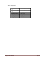
1
ZEDAR TECHNOLOGIES, INC.
Regency Spa Controller
Owner’s Manual
10/19/2009
Copyright Zedar Technologies, Inc. 2009. Specifications and information in this manual are subject to
change
Table of Contents
1.0
PREFACE ............................................................................................................................................ 4
1.0.1
1.0.1.1
Electrical Requirements ............................................................................................................ 4
Ground fault Circuit Interrupter (GFCI) ................................................................................. 4
1.0.1.1.1 GFCI In- line wiring ........................................................................................................... 4
1.0.1.1.2 GFCI 240Vac 3 wire circuit ............................................................................................... 4
1.0.1.1.3 GFCI 120/240 Vac 4 wire circuit .................................................................................... 5
1.0.1.1.4 GFCI Concerns ................................................................................................................ 5
1.0.2
Risk of Electrical Shock .............................................................................................................. 5
1.0.3
Owner’s Responsibilities ........................................................................................................... 5
2.0
OVERVIEW ......................................................................................................................................... 7
2.0.1
Control Panel............................................................................................................................. 7
2.0.2
Relay Board ............................................................................................................................... 7
2.0.3
Temperature sensors. ............................................................................................................... 7
2.0.4
System features ........................................................................................................................ 7
2.0.5
System Default Settings ............................................................................................................ 8
2.0.6
System Recommendations........................................................................................................ 8
3.0
CONTROL PANEL ............................................................................................................................... 9
3.0.1
3.0.1.1
Water Pump 1 Key................................................................................................................. 9
3.0.1.2
Water Pump 2 Key.............................................................................................................. 10
3.0.1.3
Blower 1 Key ........................................................................................................................ 10
3.0.1.4
Blower 2 Key ....................................................................................................................... 10
3.0.1.5
Done Key ............................................................................................................................. 10
3.0.1.6
Light Key .............................................................................................................................. 10
3.0.1.7
Auxiliary Key ........................................................................................................................ 10
3.0.2
4.0
Spa Control Keys ....................................................................................................................... 9
Status Control Keys ................................................................................................................. 10
CONTROLLER OPERATION ............................................................................................................... 11
4.0.1
Normal Operation ................................................................................................................... 11
4.0.2
Temperature Setting ............................................................................................................... 11
4.0.3
Spa Programming .................................................................................................................... 11
Regency Owner’s Manual
Page 2
5.0
4.0.3.1
Clock Format ....................................................................................................................... 13
4.0.3.2
Clock Setting ........................................................................................................................ 13
4.0.3.3
Date Setting ........................................................................................................................ 13
4.0.3.4
Silence Timer ....................................................................................................................... 14
4.0.3.5
Vacation Timer .................................................................................................................... 15
4.0.3.6
Spa Mode ............................................................................................................................ 16
SPA OPERATION .............................................................................................................................. 18
5.0.1
Normal Operation ................................................................................................................... 18
5.0.2
Overheat Operation ................................................................................................................ 19
5.0.3
Freeze Protection Operation................................................................................................... 19
6.0
SYSTEM SPECIFICATIONS ................................................................................................................ 21
6.0.1
Relays ...................................................................................................................................... 21
6.0.2
Electrical Outputs .................................................................................................................... 21
6.0.3
Temperature ........................................................................................................................... 22
7.0
INSTALLATION INSTRUCTIONS ........................................................................................................ 23
7.0.1
Control Panel........................................................................................................................... 23
7.0.2
System Controller.................................................................................................................... 23
8.0
7.0.2.1
Flow Sensor/ Pressure Switch.............................................................................................. 23
7.0.2.2
Thermowell ......................................................................................................................... 23
7.0.2.3
Temperature Sensor ............................................................................................................ 23
7.0.2.4
Freeze Sensor ...................................................................................................................... 24
7.0.2.5
Heater ................................................................................................................................. 24
CONTACT INFORMATION ................................................................................................................ 25
Regency Owner’s Manual
Page 3
1.0
PREFACE
1.0.1 Electrical Requirements
All Spa electrical wiring should be performed by a licensed electrician and must comply
with all NEC (National Electrical Code) and state and local code requirements.
The electrical loads for connections to this system MUST NOT exceed the rating
specified in this manual. Failure to comply with these specifications and/or improper
wiring may cause hazardous operating conditions and/or damage to the controller.
1.0.1.1 Ground fault Circuit Interrupter (GFCI)
Since January 1994, a Ground Fault Circuit Interrupter is required by all electrical Spa
installations. The National Electrical Code (NEC) also states that a service disconnects
should be located near the Spa but no closer than 5 feet. A GFCI could be used for this
purpose.
All 120 Vac Spa require a dedicated 20 Amps GFCI service connection, all 240 Spa
require a dedicated 50 Amps GFCI service connection with a 6/3 AWG (four wire) all
copper conductors. In order to conserve electricity we recommend using 240 Vac
connections in all 240 Vac capable Spa.
It should also be verified that a dedicated service is used with no other circuits
connected to it.
1.0.1.1.1 GFCI In- line wiring
•
•
Black and Red wires feeding the GFCI are connected to a properly sized circuit
breaker.
White wire should be connected to the neutral bar and the Green is connected
to the ground bar.
1.0.1.1.2 GFCI 240Vac 3 wire circuit
A 240 Vac 3 wire service could be used if it does not operate any 120 Vac devices.
•
•
Black and Red wires feeding the GFCI are connected to a properly sized circuit
breaker.
White wire is not required and the Green is connected to the ground bar.
Regency Owner’s Manual
Page 4
1.0.1.1.3 GFCI 120/240 Vac 4 wire circuit
A 240 Vac 4 wire service could be used if it does operate any 120 Vac devices.
•
•
Black and Red wires feeding the GFCI are connected to a properly sized circuit
breaker.
White wire should be connected to the neutral bar and the Green is connected
to the ground bar.
The White load wire must be connected to the neutral out terminal. Proper
installation of the neutral wire is essential for proper operation. If not wired
properly, the GFCI will trip when any of the 120 Vac devices is turned ON.
1.0.1.1.4 GFCI Concerns
If the GFCI does not stay engaged as soon as power is applied to the system, it could
indicate that it is not wired correctly. Please verify that all the connections are correct,
generally if the GFCI does not stay engaged, it is a wiring problem with the neutral wire.
The Neutral and the Ground wires cannot touch anywhere otherwise the GFCI will trip.
1.0.2 Risk of Electrical Shock
As a Spa owner some of the risks of electrical shock are but not limited to the following:
•
•
•
•
•
All supply circuits must be disconnected before accessing the Relay Board
Terminals. The cover should only be removed by a qualified technician.
Do not operate the Spa with the controller cover removed.
Use copper wire only while installing the system.
Do not allow any electrical appliance: lights, telephone, radios, televisions etc
within 5 feet of the Spa.
Never try to operate any electrical device from inside the Spa.
1.0.3 Owner’s Responsibilities
As a Spa owner some of your responsibility are but not limited to the following:
•
•
Protect your Spa from freezing or any other damage.
Do not permit children to use or access to the spa unless they are supervised at
all times.
Regency Owner’s Manual
Page 5
•
•
•
•
•
•
Before entering the Spa make sure that the water temperature never exceeds
104°C (40°C). Water temperature between 100°F (38°C) and 104°F (40°C) are
considered safe for adults use.
Pregnant or possible pregnant women should limit Spa’s water temperature to
100°F (38°C) since excessive water temperature has a high potential for causing
fetal damage.
The use of alcohol, drugs or medications before or while using the Spa made lead
to unconsciousness that could lead to drowning.
Persons with infections or sores should never use the Spa. Temperature of the
spa may allow the growth of infectious bacteria if the system is not properly
sanitized.
Persons using medication, suffering from obesity, history of heart disease, low or
high blood pressure, diabetes or problems with the circulatory system should
consult a physician before using the Spa.
Adults should never use the Spa alone, always enter and exit the Spa slowly.
Regency Owner’s Manual
Page 6
2.0
OVERVIEW
The Regency Spa Controller is a microprocessor based system designed to provide the
users with an efficient and effective way of managing their enjoyment time while using
a spa. It has been designed to provide you with maximum flexibility during the spa use
by allowing easy system programming that requires minimum effort. However it will
allow you to configure the inner workings of the spa if you choose to. The Spa could be
tailor to satisfy the user needs.
The Regency controller system package consists of:
2.0.1 Control Panel
This controller is installed on the spa consist of 10 push buttons (keys) that are used to
control pumps, air blowers, lights, any other auxiliary equipment as well as to program
the system. Some of its features are:
•
•
•
One 2 lines 24 characters LCD display.
10 momentary buttons used to select operation and controller settings.
Operating temperature 0°C to 85°C.
2.0.2 Relay Board
This board has been designed for installation below the Spa’s skirt. It provides the user
with the following features:
•
•
•
•
•
Could control for 2 pumps, 2 blowers, 2 auxiliary, lights, ozone and heater.
Inputs for sensing control switches.
Inputs for temperature sensors.
RJ45 connector for communication with the top controller.
120 or 240 Vac +/- 10% operation.
2.0.3 Temperature sensors.
The Regency system uses 2 temperature sensors: one sensor is installed on the heater
surface to provide overheat/freeze protection and the second is used to monitor the water
temperature.
2.0.4 System features
The Regency controller has been designed to meet all of the following conditions:
Regency Owner’s Manual
Page 7
•
When the water temperature is below the set point, the low speed will be turned
on, the pressure switch will be detected to determine that water is flowing through
the pipes and then the heater will be turned on.
•
When the water temperature goes over the set point the heater will be turn on but
the low speed pump will continually run for one minute.
•
The Ozone generator will be turned ON only when the pump is running in low
speed. It will be turned OFF if the pump is switch to high speed.
2.0.5 System Default Settings
All default settings of the controller including the date and the time of the day are
retained after power is removed from the system.
2.0.6 System Recommendations
In order to keep your Spa in optimum condition we recommend:
•
•
•
•
Keep you Spa user’s manual which explain how to care for your spa.
Maintain proper level of PH.
Sanitize you Spa regularly; it will extend the life of your equipment.
Keep proper chemical level in the Spa to prevent premature heater as well as
other components failure.
Please use this manual as a reference while modifying the operation of
your Spa.
Regency Owner’s Manual
Page 8
3.0
CONTROL PANEL
The control panel is installed on the lip of the spa for easy and convenient access. The
Regency model, consist of:
•
•
2 lines 20 character LCD display used to communicate the user Spa temperature,
Time of the day as well as date during normal operation. It is also use during
programming to convey all the information to the user.
10 membrane switches used to control all the different function of the Spa. They
are divided in 2 group:
Spa Control keys:
Status Control keys:
Pumps, Air Blower, Spa light, Done, Extra.
Up, Down, Programming
Note
If any of the keys in the control board is held depressed for more
than 30 seconds it will be disable, a message will be displayed
indicating this failure; after the depressed key is released it will
be reactivated. This feature will not allow the system to lock up
because of a collapsed or defective key.
3.0.1 Spa Control Keys
There are 7 Spa control keys: Pump1, Pump 2, Air 1, Air 2, Done, Spa Light and Auxiliary.
A Spa should have at least one water pump; optionally it could have a second or third pump, an
air blower, a mister or a fiber optic light setup and an extra device.
3.0.1.1 Water Pump 1 Key
Will control the primary pump which is usually a dual speed pump, the low speed is
used to filter the Spa and/or to circulate the water while the Spa is being heated. A
second depression of this switch will toggle between the high and the low speed of the
pump. If your primary pump is a single speed (HIGH speed) only, this switch will turn the
pump ON and OFF.
Regency Owner’s Manual
Page 9
Note
If the Spa is equipped with a circulating pump only, it will be
used for filtration and heating instead of the low speed pump.
3.0.1.2 Water Pump 2 Key
Will control a secondary pump On/OFF.
3.0.1.3 Blower 1 Key
Will activate the primary air blower (bubbler). It is an ON/OFF key
3.0.1.4 Blower 2 Key
Will activate the secondary air blower (bubbler). It is an ON/OFF key
3.0.1.5 Done Key
This key should be depressed after the Spa had been used. A depression of this key will
signal to the microcontroller in the system that Spa’s software management should take
over and execute the filtration cycles, heat maintenance, etc.
3.0.1.6 Light Key
Will activate the lights used in the Spa. It is an ON/OFF key
3.0.1.7 Auxiliary Key
Will activate any device attached to the Auxiliary relay in the system board. It is an
ON/OFF key
3.0.2 Status Control Keys
There are 3 status control key: UP, Down and Programming. Their function will be
explained during the Spa Programming section of this manual.
Regency Owner’s Manual
Page 10
4.0
CONTROLLER OPERATION
4.0.1 Normal Operation
The Regency Spa controller is a very easy to operate. Upon installation the LCD controller will
display defined as a default display:
DATE
Spa Temperature
Time of day
While using the Spa a depression of any of Spa control key the system will display the depressed
key and when it is released it will come back to the default display. Example; if the Pump 1 is
depressed the system will display:
Pump 1
Spa Temperature
Time of day
After few seconds it will return to the default display.
4.0.2 Temperature Setting
A depression of either the Up or Down key will command the controller to enter the
temperature setting mode by displaying:
Temperature Setting
<Current Spa Temperature>
Holding either key depressed will scroll the setting from 90 to 105 degrees Fahrenheit.
4.0.3 Spa Programming
Depressing the Programming key will command the controller to enter the programming mode
by displaying:
Regency Owner’s Manual
Page 11
Spa Programming
Wait few seconds
IMPORTANT NOTICE
Once the programming mode is entered depressing the Up or
Down key will allow the user to scroll through all the setting. If
while the system is displaying a setting, and the Programming key
is depressed the user will be allow to modify the setting using the
Up or Down Keys. After the desire setting is selected a depression of
the Programming key will save the entry by displaying:
Saving Entry
<Programmed Entry>
A depression Done key will clear the entry and the old values will
be retained.
Cancelling Entry
<Programmed Entry>
If while trying to program a setting; a key is not depressed for a
period of 10 seconds the system will automatically exit the
programming mode and the selected setting will not be saved in
memory, it will display the following screen for few seconds and
then the default screen .
Exiting
Programmed Mode
Regency Owner’s Manual
Page 12
4.0.3.1 Clock Format
As described above after few seconds the system will enter the Programming mode and it will
display:
Clock Format
<Current clock mode>
Clock modes are: 12 hours or 24 hours format.
If no changes are required a depression of either the Up or Down key will display the previous or
the next available settings.
While on this screen is being displayed a second depression of the programming key will allow
the user to set the desired clock mode by depressing the Up or Down keys.
4.0.3.2 Clock Setting
The next available setting will be the Clock Setting.
Clock Setting
<Current clock setting>
If the Clock format was set to the 12 HOURS format: a depression of the Programming key will
allow the user to set the HOURS, a second the MINUTES, a third either PM or AM, a fourth will
save the programmed value. Follow similar procedure for 24 HOURS format.
All the mentioned depressions have to be executed in order to set the time properly.
4.0.3.3 Date Setting
The next available setting will be the Date Setting.
Date Setting
<Current date setting>
While the above screen is been displayed a depression of the Programming key will allow to set
the DAY of the week, a second the MONTH, a third the DATE, a fourth the YEAR, a fifth will save
the programmed value.
Regency Owner’s Manual
Page 13
All the mentioned depressions have to be executed in order to set the Date properly.
4.0.3.4 Silence Timer
The next available setting will be the Silence Timer.
Silence timer is a period during which the system will be dormant, it will override the filtration
cycles, as well as temperature sampling, except if the temperature drops below 40 degrees
Fahrenheit. However, the user could still have full control of the system if it needs to use the Spa
by simply depressing any of the keys. After using the spa it will return to the silence mode if
required.
While the screen bellow is being displayed:
Silence Timer
<Starting Time>
<Ending Time>
Upon depression of the Programming key the system will display:
Silence Timer
Start
<Starting Time>
And allow the user to enter the Silence Timer Starting Hours, next depression the MINUTES,
next AM/PM if the clock mode was set to 12 hours format. Finally it will display the following
screen:
Silence Timer
Stop
<Ending Time>
Follow the previously described procedure to enter the Ending time. Please make sure that the
last screen
Saving Entry
Regency Owner’s Manual
Page 14
4.0.3.5 Vacation Timer
The next available setting will be the Vacation Timer.
The Vacation timer is used for a period during which the system will be dormant, it will execute
the filtration cycles but not temperature sampling, except if the temperature drops below 40°F. .
However, similar to the Silence Timer the user could still have full control of the system if it
needs to use the Spa by simply depressing any of the key, after using the spa it will return to the
vacation mode if required.
While the screen bellow is being displayed:
Vacation Timer
<Mode>
The modes are: OFF or ON (ACTIVE). The mode is selected by depressing the Programming Key
and then either the Up or Down key to set the desired mode.
If the mode ON is selected the system will display:
Start Vacation date
<Current Starting date>
A depression of the Programming mode will set MONTH, a second depression the DATE
and finally the YEAR, next depression will command the controller to display:
End Vacation date
<Current ending date>
While the above screen is displayed, follow the same previously described process to set
the end of vacation date.
Regency Owner’s Manual
Page 15
4.0.3.6 Spa Mode
The next available setting will be the Spa Mode. There are two Spa Modes: Auto,
Manual.
Auto mode: Will allow the Spa controller will execute all the default function as
programmed at the factory (RECOMENDED MODE).
Manual Mode: Let the user set all the spa parameters as follows.
The first parameter is the filter cycles, this screen will allow the user to set the number of filter
cycles during an 24 hours period, the maximum number of cycles is 4 and could be set by
depressing the Programming key and then either the Up or Down keys until the desire setting is
obtained then saved by depressing the Programming key one more time:
Manual Mode
Filter Cycle
<# of cycles>
Next screen is the cool down cycle; the maximum setting is 180 seconds. It is defined as the
number of seconds the pump will run after the heater is turned off:
Manual Mode
Cool Down Cycle
< #Seconds>
Next screen is the clear cycle; the maximum setting is 180 seconds. It is defined as the number
of minutes the air blower will run to clear some stagnated water in its pipes:
Manual Mode
Clear Cycle
<# minutes>
Next screen is the Post filtration cycle, the maximum setting is 180 minutes the minimum 30
minutes. It is defined as the number of minutes after the user exit the Spa.
Manual Mode
Post Fil
Regency Owner’s Manual
<Ending Time>
Page 16
Next screen is the User Time Out; the maximum setting is 60 minutes. It is defined as the
number of minutes the system has not sense any key have been depressed and should enter the
Post Filtration Cycle:
Manual Mode
User Time Out
Regency Owner’s Manual
<# minutes>
Page 17
5.0
SPA OPERATION
Once the Regency controller is installed, the spa should have the following modes of operation:
5.0.1 Normal Operation
The Regency Spa system is very easy to operate. Upon powering up the system will set the Spa
according to the factory default values, if the pressure switch is not installed the unit will
display:
Pressure switch
failure
After the pressure switch is installed or replaced, the system it will enter a filtering cycle and will
start heating up the water until the set temperature is achieved, then it will display the following
display:
DATE
Spa Temperature
Time of day
While using the Spa a depression of any of Spa control key will command the system to display
the depressed key, when it is released it will return to the default display. Example; if the Pump
1 is depressed the system will display:
Pump 1
Spa Temperature
Time of day
After few seconds it will return to the default display.
It is recommended to depress the DONE key after the Spa is used, however if this is not done,
the system is able to detect that it has not been used for a programmed period of time. When
either condition occurs the system will enter the filtering cycle mode and display:
Filtering Cycle On
Spa Temperature
Regency Owner’s Manual
Time of day
Page 18
A depression of any key will exit this mode and return the system to the normal mode until the
above condition happens again. Then after the filtering cycle is done the system will return to
the default display.
5.0.2 Overheat Operation
When the water temperature is sensed to be high than 112°F (44°C), the heater will be TURNED
OFF, while keeping the Low Pump running. The system will indicate this condition by displaying:
Danger water too hot
Spa Temperature
Time of day
If the temperature keep on raising the system will display the following screen:
Danger water too hot
System failure
Please remove power from the unit and call a certified technician.
5.0.3 Freeze Protection Operation
When the water temperature is sensed to be below 45°F (7°C) the low speed pump and the
heater will be TURNED ON, the system will blink the following display:
Water too cold
Spa Temperature
Time of day
If the temperature does not on raises, the low speed pump will stay ON; the system will display
the following screen:
Water too cold
System failure
Please remove water from the spa, power from the unit and call a certified technician.
Regency Owner’s Manual
Page 19
However if the temperature raises and reaches 50°C (10°C) the system will blink the following
display:
Water cold
Spa Temperature
Regency Owner’s Manual
Time of day
Page 20
6.0
SYSTEM SPECIFICATIONS
6.0.1 Relays
ABSOLUTE MAXIMUM RATING
Ambient Temperature 25°C.
Pump Relays
Blower Relays
Heater Relay
Auxiliary I Relay
Auxiliary II Relay
Light Relay
Ozone Generator Relay
30 Amps @ 240Vac
30 Amps @ 240Vac
30 Amps @ 240Vac
30 Amps @ 240Vac
30 Amps @ 240Vac
10 Amps @ 240Vac
10 Amps @ 240Vac
6.0.2 Electrical Outputs
ABSOLUTE MAXIMUM RATING
Ambient Temperature 25°C.
Pump (HI)
Pump (LOW)
Heater
Auxiliary I
Auxiliary II
Light
Ozone Generator
14 Amps @ 120Vac
10 Amps @ 120Vac
2 KW @120Vac
4 Amps @ 120Vac
4 Amps @ 120Vac
1 Amps @ 12Vac
3 Amps @ 120Vac
12 Amps @ 240Vac
8 Amps @ 240Vac
4 KW @ 240Vac
4 Amps @ 120Vac
4 Amps @ 120Vac
2 Amps @ 240 Vac
NOTE
The total current output of all devices MUST never exceed
the input rating.
Higher heater wattage could be used as long as the total
combined does not exceed the rated input supply.
Regency Owner’s Manual
Page 21
6.0.3 Temperature
Temperature Indicating
Range
Temperature Setting
Range
Factory Set
Temperature Accuracy
Overheat Temperature
Freeze Temperature
Working Temperature
Regency Owner’s Manual
30°F to 120°F (1°C to 50°C)
60°F to 104°F (15°C to 40°C)
100°F (38°C)
+/- 2°F (+/- 1°C)
112°F (44.5°C)
45°F (7°C)
-20°F to 85°F
Page 22
7.0
INSTALLATION INSTRUCTIONS
7.0.1 Control Panel
Locate a flat area around the rim of the Spa and cut a hole using the cut out template furnished
with the system. Make sure a location is select that allows the control panel to reach the
system controller. Do not continue installing the control panel until the system controller is
wired and installed in the Spa.
Then clean the cut out with a 50/50 mixture of isopropyl alcohol around the area so that all the
dust and contaminant are removed, remove the paper backing feed the cable through the hole
and place the bezel over the hole pressing it firmly and evenly, then connect the provided cable
to the system controller housing.
7.0.2 System Controller
Choose a sturdy location close to the heater in order to minimize the wire length between them;
the system controller is shipped wired to customer requirements.
The controller’s cover is removed by disconnecting the two screws holding the front cover, and
then the Spa equipment should be connected according to the provided schematic.
7.0.2.1 Flow Sensor/ Pressure Switch
The heater will not be activated unless the flow sensor/Pressure switch is connected and water
flow is detected.
If not already installed in the Spa, install a new sensor as follows:
• Screw the new sensor into the threaded port in the heater
• Do not over-tightening the sensor, it could strip the threads or crack the heater housing.
• Connect the wires as indicated in the provided schematic.
7.0.2.2 Thermowell
The thermowell should be located 10” bellow the normal water level of the spa.
7.0.2.3 Temperature Sensor
The temperature sensor is the sensor with the larger diameter stainless steel probe and longer
cable. The Spa temperature sensor is to be installed in a thermowell.
Regency Owner’s Manual
Page 23
7.0.2.4 Freeze Sensor
The freeze sensor is the sensor with the smaller diameter .250” diameter stainless steel probe
and shorter cable.
Install it following the following procedure:
• Insert the sensor into the groove located on the heater tube under the clip.
• Make sure that the sensor is covered by the foam gasket under the clip.
• Connect the sensor to the printed circuit board at the position indicated in the
schematic.
7.0.2.5 Heater
The Black and White heater wires should be connected to the board terminal and the Green
wire to the grounding plate.
Regency Owner’s Manual
Page 24
8.0
CONTACT INFORMATION
ZEDAR TECHNOLOGIES, Inc.
700 E. Lee St.
Elk Grove Village, IL 60007
Phone: 630-502-7238
Fax: 847-228-1816
GENERAL INFORMATION
[email protected]
Visit us on the Internet
www.zedartech.com
Regency Owner’s Manual
Page 25