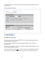
1
User’s Manual M222 Web-to-Wireless Remote Monitor and Control System Boise Research Center 12554 W. Bridger Street Boise, ID 83713 208-947-9500 [email protected] Last revision: 5-23-2008 1 Table of Contents Introduction _____________________________________________________________ 4 Operation is very simple ___________________________________________________ 6 How it Works ____________________________________________________________ 6 • Using the Cellular Network _____________________________________________ 6 Two Remote Control Outputs – M222 or M202 __________________________________ 8 Optional - Wireless Remote Inputs & Outputs (RIO) ______________________________ 8 Reports ________________________________________________________________ 8 • Maintenance Mode ___________________________________________________ 9 Integrated Power Supply ___________________________________________________ 9 Getting Started ___________________________________________________________ 9 Connecting the M222 to a PC ______________________________________________ 0: Check Cell Service _________________________________________________ 1: Full Communication Test ____________________________________________ 2: Read & Set Input Values _____________________________________________ 3: Control Outputs ____________________________________________________ 4: Local Programming _________________________________________________ Digital Inputs 1 & 2_________________________________________________ Analog Inputs 1 & 2 ________________________________________________ Digital Outputs 1 & 2 _______________________________________________ Time Scheduled Reports ____________________________________________ Call Limit ________________________________________________________ • Low Power Mode ____________________________________________________ 5: Restore Factory Defaults ____________________________________________ 6: Clear Daily Call Counter _____________________________________________ 7: Send Status Report _________________________________________________ 8: Display Status Messages ____________________________________________ 10 11 11 11 11 11 12 13 14 17 17 17 18 18 18 18 Tech Support ___________________________________________________________ 19 Installing the M222 _______________________________________________________ 20 • Selecting an installation location ________________________________________ 20 • Testing the receiver strength ___________________________________________ 20 M222 Trouble Shooting ___________________________________________________ 21 • Troubleshooting Transmission or Cellular Reception Problems ________________ 22 Wiring Instructions ______________________________________________________ • Applying Power to the M222 ___________________________________________ • Connecting to Digital Inputs 1 & 2 _______________________________________ • Analog Inputs _______________________________________________________ • Output Connections __________________________________________________ 2 24 25 25 25 25 M2M Network Operation Center ____________________________________________ 27 Using the Web Site_______________________________________________________ 27 • Logging In _________________________________________________________ 27 Device List _____________________________________________________________ 28 Viewing Monitored Inputs on the Status Summary Screen ________________________ 28 Main Menu > Account Summary ____________________________________________ 29 User Management _______________________________________________________ 30 Device Setup____________________________________________________________ Step # 1 - Device Specific Information ____________________________________ Step # 2 - Phone & E-Mail Contacts ______________________________________ Step # 3 - Contact lists ________________________________________________ Step # 4 – Display Settings _____________________________________________ Step # 5 - Event Notification ____________________________________________ Step # 6 – Device Groups ______________________________________________ 31 32 33 34 35 37 38 Device History __________________________________________________________ 38 Commands _____________________________________________________________ 39 Monitoring and Controlling the M222 via Inbound Telephone ___________________ 42 RIO Slave Setup- M222 Slave Only __________________________________________ 43 3 Introduction The M222 is a low cost web-to-wireless remote monitor and control systems. The internal wireless modem provides two-way communications to the automated M2M operations center and the www.m2mcomm.com web site. Dual mode (analog/digital) cellular communications provides very wide spread coverage throughout North America with no requirement for a local cellular account. This user’s manual covers the model M222, which is member of a family of several related products. M222 Directly monitors up to 2 digital inputs, 2 analog inputs, and controls 2 relay outputs. M844 Directly monitors up to 8 digital inputs, 4 analog inputs, and controls 4 relay outputs. M2000 Monitors and controls other Intelligent Electronic Devices using a Modbus port. M2500 Directly monitors up to 10 digital inputs, which can be configured as alarms, counters, or counter/timers. M2510 Combines both the M2000 & M2500 – Monitor and control other Intelligent Electronic Devices using a Modbus port and monitor 10 direct connect digital inputs. M3000 Directly monitors up to 10 digital inputs and 3 analog inputs. Directly controls 3 output relays. 4 In this manual, the unit is generically described as the M222. This product is available with three different loading options: 1. The M200 features only two digital inputs. The analog inputs and digital outputs are not loaded. 2. The M222 features two digital inputs and two digital outputs. The analog inputs are not loaded. 3. The M222 has two each of the digital and analog inputs, as well as two digital outputs. The inputs and outputs of the M222 are suitable for a wide range of direct connect monitoring and control applications. The model M222 directly monitors up to two digital inputs, which are dry contact inputs. The M222 also has two remote control relays. The features of the M222 have been optimized to operate as a general purpose remote monitor and control system. • Flexible remote control on/off schedules can be set from the web site 5 • • One command opens normally closed relay outputs for a programmable amount of time High voltage power supply including 120, 240, and 480 VAC The M222 maximizes the potential of the communication network by internally testing the data from monitored devices and only sending data when a reportable event occurs. Reports are transmitted when: • • • A monitored input or output changes or A control command or report request is received from the web site or A time scheduled report is due Operation is very simple 1. Connect the M222 to the equipment to be monitored and turn it on. 2. The M222 will automatically establish two-way communications over the public cellular network to the www.m2mcomm.com web site. 3. Log onto your private page on the secure web site to: View the last reported status of your equipment – switch positions, equipment on/off status, tank levels … Request an updated status report from the unit. Send a command to open or close a relay (turn off or on a piece of equipment) now Schedule one or more future commands. Configure selected events to trigger an immediate user notification by voice phone or e-mail. How it Works Using the Cellular Network When an M222 uses the cellular network to make a call from anywhere in North America (where there is cellular coverage), it is recognized locally as a roaming cell phone. As a part of the standard roaming protocol, the local cellular network automatically passes the module's identification numbers and data to the central cellular hub. The M2M module passes its data packet in the normally non-utilized data field. This technique allows the transmission of an identification number and the time and date, plus 23 digits of customer specific data, all at a very low cost. At the M2M network operations center, the data is validated and processed for distribution to the end user. In addition, configuration information can be sent from the M2M data center to the M222. This is called cellular control channel communications. The primary advantages of this method are low cost and wide spread coverage throughout North America. The disadvantage is that the customer specific data packet is relatively small. The control channel is best suited for applications that send a small amount of data infrequently. 6 Two Direct Connect Digital Inputs- All models The model M222 is equipped with 2 digital status inputs. Both inputs are opto-isolated and protected with surge suppression circuitry per ANSI C37.90.1-2002 to minimize the effect of external transient voltages. The inputs are designed to monitor dry contacts only. Do not apply any external voltage to these inputs. To monitor the presence or absence of 120, 240, or 480 VAC, order the model # M202HV. The unit will report the state of both inputs when any input changes state in either direction (on-off or off-on) for longer than a programmable trigger time. The trigger time of each alarm style input is programmable by the user through the local programming utility and can be varied from 1 to 240 seconds. Any state change that does not remain stable for the specified trigger time will be ignored. The factory default trigger time is 5 seconds. Counter / Timer Options The digital inputs can also be individually configured as counter / timers. There are two counter reporting options: 1. Report the counts since the last report -- plus the time the input was closed. This is useful for time scheduled reports such as “The pump turned on 8 times today and ran for 4 hours and 12 minutes.” 2. Delta or “Flow Meter” mode – reports the number of counts per minute. The value is updated every minute. In this mode, the timer isn’t relevant and is reported as 0. Counter inputs will count all state changes that are stable for at least 10mS. The timer function tests the input once per second and increments the run-time timer if the input is closed. Two Analog Inputs- M222 only Two analog inputs are configured to monitor 0-10 VDC or 0-20 mA input signals (jumper selectable). Other values can be ordered as factory options. Two programmable set points and one trigger time can be locally programmed for each input. When the monitored signal crosses a set point for the specified trigger timer, a range change report may be sent. The A-D converter has 10-bit resolution, so the analog report sends the measured signal(s) as a number from 0-1023. At the M2M web server, offsets, scalars and lookup tables are available to convert the raw numbers into meaningful values such as temperature, tank level, pressure, etc. These flexible conversion options allow the system to monitor and accurately interpret many types of sensors. The analog report also includes the present range (such as low, medium, high) of the monitored signal. Analog inputs are protected with surge suppression circuitry per ANSI C37.90.1 7 Two Remote Control Outputs – M222 or M202 The M222 is equipped with two on-board digital status inputs. Both are protected with surge suppression circuitry per ANSI C37.90.1-2002 to minimize the effect of external transient voltages. In the standard product configuration, the inputs can be configured to report (or not report) all state changes The standard product is configured to monitor dry contact inputs. A 12 VDC wetting voltage is supplied to the two common terminal points. No external voltage is required. The M222 can report the state of all inputs when any input changes state in either direction (open-closed or closed-open) for longer than the programmable trigger time. The trigger time of each input is set by the user through a local programming utility and can be varied from a minimum of 1 second to a maximum of 240 seconds. Any change that does not remain stable for the specified trigger time will be ignored. The factory default trigger time is 5 seconds. Optional - Wireless Remote Inputs & Outputs (RIO) Up to six wireless RIO slave units can be added to each M222. A RIO slave is the same product as the M222 except that it has no cellular modem and it reports to the web server through a M222 master device. Each slave has the same input and output configuration options as the standard model. The remote slave inputs and outputs operate the same as the M222 master’s on-board inputs and outputs. With 3 slave units, the status of the 2 master I/O points and up to 6 remote I/O’s can be reported to the web server. Up to 2 master and 6 slave outputs can be controlled from the same M222 Send Commands screen. An Example Configuration with One RIO Slave Unit: Reports The M222 is a wireless remote monitoring device that communicates over the cellular network. Some of the features and reports are configurable and can be enabled or disabled by M2M and/or the user. (1) A status report can be requested at any time from the web site. (2) When powered on, the unit will report “Power On”. 8 (3) When powered off for more than one minute, the unit will report “Power Off”. (If equipped with an internal battery) (4) Reports can be sent when an input changes state (5) An acknowledgement will be sent when any output is controlled. Time based controls will also trigger a report when the control time is over and the output switches again. For example, if Output #1 is turned on for 1 hour, an ACK will be returned immediately and then again in one hour when the output turns off. The M222’s status report contains the following information: • • • • • • • • • • • Call Reason Number of Transmission Attempts Model Number The on/off state of the 2 digital inputs The on/off state of the 2 controlled outputs The Cellular Signal Strength Expanded I/O information AC Power on/off (when the battery is included) Daily Call Limit Exceeded? (yes/no) Maintenance Mode on/off Time Scheduled Reports Enabled? (yes/no) Maintenance Mode The unit can be placed in a local maintenance mode by setting the daily call limit to 228. When Local Maintenance Mode is ON, all event-based reports will be disabled. This is normally used to prevent unwanted transmissions while the unit is being installed or serviced. The unit can be placed in a remote maintenance mode with a command from the web site. When Remote Maintenance Mode is ON, all event-based reports will be disabled. In addition, all remote commands will be ignored, except for the command to end the remote maintenance mode and return to normal operation. Integrated Power Supply The standard M222 includes terminal strip points and transformer taps that allow it to be operated from 120, 240 or 480 VAC. Getting Started Setting up your M2M monitoring device is a three-step process. 1. Configure the unit for your specific monitoring and reporting requirements. 9 2. Attach the M222 to the equipment that you want to monitor or control, and 3. Set up the device information on the M2M (www.m2mcomm.com) web site. This manual gives you the information you need to get started. There are two primary sections: • • Programming, installing, and using the M2M M222 Communicator, and Using the M2M web site. Connecting the M222 to a PC An on-board serial port allows local programming and configuration from a PC, laptop computer, or ‘Palm Pilot’. An adapter cable is required to connect to a standard DB-9 serial connector. The M222 will detect the connection of a remote communication program running on a standard RS232 device and will connect the serial connector to the microprocessor’s serial port. An external terminal, PC, or Palm Pilot with a terminal emulator program can then be used to set the unit’s programmable parameters and to locally test the inputs and outputs. 1. On a PC, run the Windows Terminal or Hyper Terminal program. Commercially available terminal emulator programs such as ProComm or Hyper Access can also be used, and offer more advanced features and ease of use. 2. Set the terminal communications settings to 38,400 baud, 8 bits, 1 stop bit, no parity, and no flow control. Verify the comm. port is set to the serial port where you connected the cable, and that there are no conflicts with other serial devices such as the modem. 3. If your computer doesn’t have a RS-232 serial port, then use a USB-to-serial converter to create a serial port. These converters are readily available from most computer stores or from M2M Communications. 4. Use a 9 pin serial cable / adapter to connect the M222 to the PC’s serial port. When both the communication program is running AND the connector connected, the M222 will automatically detect the PC. Both the red and green RSSI LEDs will be turned on and it will enter the local programming mode. The following menu will be displayed to the PC: M2M Communications M222 w/Dual Mode Communications Version NN 0: Check Cell Service 1: Full Communication Test 10 2: 3: 4: 5: 6: 7: 8: Read & Set Input Values Control Outputs Local Programming Restore Factory Defaults Clear Daily Call Counter Send Status Report Display Status Messages 0: Check Cell Service Cellular information and the RSSI (signal strength) can be measured and displayed. This is especially useful when testing fringe area signal strength and antenna orientation. 1: Full Communication Test This choice will initiate a “full circle” cellular test. The M222 will transmit a status report and request an Acknowledgement. The M2M web site will then send the ACK. The unit will wait for up to 2 minutes for this ACK. This process verifies the unit’s ability to both transmit and receive 2: Read & Set Input Values From the same PC connection, the current status of the digital inputs can be displayed to the PC. This is useful for local verification of both the unit and the monitored inputs. Input changes made during the local input test are not reported to the web site. 3: Control Outputs From the same PC connection, the controlled outputs can be turned on or off. This is useful for local verification of both the unit and the controlled equipment. Output changes made during the local output test are not reported to the web site. While the outputs are being controlled from the local output test, any local (automatic) control routines are disabled. 4: Local Programming The M222 will be delivered from the factory with the programmable parameters preset to default values. To change those settings before installing the M222 (or at any time in the future) connect the unit to a PC with a serial cable. Note that remote communications will be disabled during the Local Programming process. By entering choice #4, the programmable parameters can be entered and edited as many times as desired. The entries are range checked as they are entered and illegal values will 11 be rejected. If the displayed value is correct, simply press Enter to leave it unchanged. Basic backspace functionality is also supported. Digital Inputs 1 & 2 The trigger times for each input can be specified in one second increments from 0 to 240 seconds. If any monitored (digital) input changes and the change lasts longer than the specified number of seconds, it will be reported. If it does not last this long, it will be ignored and will not be reported. Each specific input can be enabled or disabled. If (and only if) enabled, the status of the input will be displayed on the web site. In addition, the reporting of input changes for any specific input can be disabled. This will disable the trigger time for that input change and changes to that input will not initiate a report. When other inputs change for their trigger times, the status of all enabled inputs are reported. The factory default setting is 5 seconds. Press Enter to keep it or enter a new number of minutes and seconds Default = alarm inputs Example for Input # 1: Digital Input 1: Enable(1) or Disable(0)? 1 Configure as a Counter/Timer? Yes(1), No(0) 0 Report on Change? Yes(1), No(0) 1 Trigger Time (Seconds,0-240): 5 Choose Alarm or Timer/Counter functionality for the inputs: The inputs can be configured as either high-speed counter inputs or alarm (open/close) inputs. Example for Input # 1: Digital Input 1: Enable(1) or Disable(0)? 1 Configure as a Counter/Timer? Yes(1), No(0) 0 Report Counts Since Last Report (0) or Counts/Minute (1)? 0 1 There are two counter reporting options: 1. Report the counts since the last report -- plus the time the input was closed. This is useful for time scheduled reports such as: The pump turned on 8 times today and ran for 4 hours and 12 minutes.” 12 2. Delta or “Flow Meter” mode – reports the number of counts per minute. The value is updated every minute. In this mode, the timer isn’t relevant and is reported as 0. A counter input will count all state changes that are stable for at least 10mS. The timer function tests the input once per second and increments the run-time timer if the input is closed. Each counter is a 4 digit counter (0000-9999). The timers report the number of minutes and seconds that the input has been closed since the last report. The timer is reported as 00009999 minutes and 00-59 seconds A typical application of a timer/counter would be a pump monitor. - Set the input to be a timer / counter. - Schedule the timer / counter report (Time Scheduled Report #3) to be made at a desired frequency and time, such as every 24 hours at midnight. Note that no report will be made when the contacts open and close, so you must either time schedule this report or request it from the web server - The M222 will then report the number of times the pump turned on during the last day, plus the length of time that it ran (the time the input sensed 120 VAC.) Analog Inputs 1 & 2 An on-board jumper can be used to select either 0-10 VDC or 0-20 mA operation. Two set points and one trigger time per input can be specified for each input. (0 = set point disabled) Low set point High set point Trigger Time 0-1023 0-1023 0-240 seconds Sample Analog Prompt: Analog Input 1: Enable(1) or Disable(0)? 1 Low Set Point(0-1023): 100 High Set Point(0-1023):400 Trigger Time (Seconds,0-240): 5 Report on Change? Yes(1), No(0)1 The M222 will report a raw value for each input of 0-1023 to the web site, where it can be converted to a more meaningful value by the use of either a formula or a look-up table. 13 Digital Outputs 1 & 2 Output 1= Disable(0) or Enable(1)? 1 Enable Automatic Control? Yes (1) No (0) 0 All outputs can be configured as: (1) Remotely controlled from the M2M web site or (2) Automatic In the remote control configuration, any output relay can be closed (turned on) or opened (turned off), either permanently or for a specified period of time, from 1-9999 minutes. In the automatic mode, each output relay can be locally controlled based on the state of remotely monitored switches and/or sensors. More specifically, the outputs can be configured to “follow” a remote analog or digital input. This control option can be changed from the web site at any time. For example, any output may normally be controlled based on local conditions, but can be individually overridden at any time by a command from the web site Mapping the Inputs and Outputs Each output can be locally controlled based on a user-assigned analog or digital input. The following diagram is one example: 14 Each output relay has a common terminal point plus two other contacts - a normally open and a normally closed relay connection. Following a digital input: • If the corresponding input is closed (on), then the control relay will be energized. The normally open (NO) point will be closed and the normally closed (NC) point will be open. • If the corresponding input is open (off), then the control relay will be de-energized. (The normally open point will be open and the normally closed point will be closed). To set up the output so that its state complements the state of the input, simply wire to the common and NC terminal points, so that closing an input will open the control relay. Following an analog input: At the local board level, each analog input is measured as a value from 0-1023. Ranges: Two setpoints can be entered for each analog input. These setpoints are used to categorize the measured value into one of three ranges: 0, 1, or 2. If the measured value is ≤ the low set point, the range = 0 Else, if the measured value is ≤ the high set point, the range = 1 Else, the measured value is > the high set point, and the range = 2 For example if the setpoints are 500 and 600, then a measured value ≤ 500 is in Range 0 > 500 and ≤ 600 is in Range1 > 600 is in Range 2 When a measured analog value crosses a setpoint and stays there for longer than the specified trigger time, then the range will change. Range 1 provides serves as a dead band and changes into range 1 will be ignored. Outputs can be controlled when a measured value changes to range 0 or 2. • The relay will be energized when the analog range = 2. (The normally open point will be closed and the normally closed point will be open). • The relay will be de-energized when the analog range = 0. (The normally open point will be open and the normally closed point will be closed). 15 Note that a load can be turned on or off based on the analog value being in either range 0 or 2. • Connect to the Normally Open contact point to close the relay (turn a load on) when the analog range = 2 and open the relay (turn the load off) when the range = 0. • Connect to the Normally Closed contact point to open the relay (turn a load off) when the analog range = 2 and close the relay (turn the load on) when the range = 0. Application Examples: A greenhouse temperature is being monitored. Assume that: o a temperature of 70 degrees F = an analog reading of 500 o a temperature of 80 degrees F = an analog reading of 600 Assume that the setpoints are set to 500 and 600 (70 & 80 degrees) If the temperature exceeds 80 degrees, a fan can be turned on. If the temperature drops below 70 degrees, a fan can be turned off. A water tank level (or pressure) is being monitored. Assume that: o a high level = an analog reading of 800 o a low level = an analog reading of 350 Assume that the setpoints are set to 350 and 800 (low and high levels) When the water level becomes low, the pump can be turned on. When the water level becomes high, the pump can be turned off. I/O mapping can by configured by answering the following questions for each enabled output: 1. Is automatic control to be enabled? 2. What is the controlling input # (1-8). 16 Time Scheduled Reports Time Scheduled Reports can be used to report the status of monitored equipment at a specified frequency such as every 24 hours. Time Scheduled Status Report Frequency (hours, 0-240): 24 These reports can also be used as an infrequent “heartbeat” call to ensure that the unit is operating normally. The time scheduled reports can be enabled or disabled from the web site. The report frequency should be pre-set in this step. The time scheduled reports will occur at N hours after they are initiated, such as N hours after power-up, or N hours after being enabled from the web site. The report time will be reset when one of these events occur. Call Limit To reduce the number of calls that might result from over-active inputs or power cycling conditions, the number of event-based calls per 24 hours is limited. Time scheduled calls, user requested status calls and command acknowledgements will continue to be placed even after the call limit has been reached. The daily limit can be set from 1 to 20. Number of event based calls per day (1-20): Default =10 Special entry = 227 = Unlimited calls = for testing only, not recommended for field use Special entry #2 = 228 = Local Maintenance Mode = Disables all outgoing reports. (Incoming commands are not disabled) Call Limit per day (1-20): 10 Low Power Mode Low power mode is designed for applications with limited power requirements. The Normal power mode should be used whenever possible. In the low power mode, the radio is turned off to conserve power and therefore is unable to receive remote requests for input status reports. However, all other functionality remains active. If an input changes or a time-scheduled report is due, the radio will be temporarily turned on to make the call. Enable Low Power Mode? Caution: Radio will be turned off when not in use 17 Yes (1) No (0) 0 After the last entry has been entered, the following message will appear: End of local Programming To permanently save changes press “s” To exit without saving, press Esc The other menu choices may used to test and configure the unit. 5: Restore Factory Defaults The original factory default settings can be reloaded into permanent memory at any time. 6: Clear Daily Call Counter Reset the daily call counter to 0. If the unit reports that you have exceeded the daily call limit then use this to clear the daily call count. The counter can also be cleared remotely from the web site. 7: Send Status Report A Status Report containing the most up-to-date information on the M222’s digital inputs and outputs will be sent to the NOC. 8: Display Status Messages The M222 will send informative status messages to the PC as conditions change or events occur. These messages help to understand what the system is doing and are useful for troubleshooting. If the unit is powered up with the PC and terminal emulator already on, the M222 will automatically start sending these messages. If not, select this choice on the main menu. To stop the status messages and return to the menu, press any key. Some example messages are listed below: • • • • • • Power On Successful Status OK / Waiting for input change Cellular Coverage Found Checking for Cell Service Cellular Signal is Too Low Cellular Signal is Good 18 • • • • • • Cellular Signal is Excellent Transmission Initiated Transmission Successful Transmit Error – Retrying Daily Call Limit Exceeded Action Request received from NOC End the local programming session by either removing the connector or by selecting menu choice #8 = Display Status Messages. Note: While in the menu options, remote communications are disabled. The one exception is the Display Status Messages choice which displays the system status and gives a good explanation of what is happening Tech Support For assistance, questions, or suggestions, feel free to contact us. Office hours are 8-5 Monday-Friday. The contact number is 208-947-9500. For prompt answers by E-mail, please describe the problems carefully. The address is [email protected]. 19 Installing the M222 The installation process for the M222 can be divided into three steps: • • • Select an installation location. Test the device’s ability to send and receive data. Attach the device to monitored inputs and equipment to be controlled. Selecting an installation location The installation location will likely be determined to a great extent by the nature of the contacts or sensors that you want to monitor or control. The recommended operating temperature range is -22 to 140 degrees F (-30 to 60 C). The recommended relative humidity range is 5 - 95% non-condensing. A variety of pre-approved antennas are available to match the environment and signal conditions. The standard cellular antenna is mounted inside the door, and should be fine for most locations. If desired, a remote antenna with higher gain can be attached to the connector. In any case, the antenna should be located outside of any metal box or cabinet. Testing the receiver strength For cellular radios, the signal strength will vary depending on the location, and can be measured. After you have selected an installation location, it is a good idea to test the device’s ability to transmit and receive before performing the actual installation. The Radio Signal Strength Indication (RSSI) can be tested in three different ways. (1) If the unit is able to transmit, the RSSI will be reported to the website in the Power-On call. (2) If a computer is connected and the Local Programmer utility is running, the RSSI can be read and displayed by clicking the Check Cell Service selection from the menu. (3) To test the signal strength locally with no computer, wait until all LEDs have stopped blinking. Press and release the small black test switch near the edge of the radio for less than 2 seconds. The M222 will then read the Radio Signal Strength Indication (RSSI) from the radio. The signal strength is displayed using the two LED’s. They are the red and the green LEDs labeled RSSI. The signal strength can be determined with the following table: LED Appearance Solid red Red blink Green blink Solid Green blink Meaning Inadequate signal strength Weak signal strength Good signal strength Excellent signal strength 20 Notes: 1. These range descriptions are meant to be helpful in understanding the range of signal strength. Obviously, Excellent signal strength is better than Good signal and it is worthwhile to orient the antenna to receive the strongest signal. If the signal is Inadequate, try re-orienting the antenna or changing the mounting location. Note that it may be possible to improve inadequate signal strength with a directional or high gain antenna. High gain Yagi and omni-directional antennas are available from M2M Communications. After maximizing the signal strength, proceed with the installation. 2. Pressing the button for more than two seconds will initiate a test report to the web site. This step will also clear the daily call count. This is useful if you don’t have a laptop handy. M222 Trouble Shooting 1. Verify that the unit has power. There is a green “PWR” LED. It should be ON. 2. Verify that the antenna is tightly connected (just plugged in, not a threaded connector). 3. A black plastic RJ45 9-pin serial port allows local programming and configuration from a PC or laptop. A PC with a terminal emulator program (i.e. HyperTerminal, HyperAccess) can then be used to set the unit’s programmable parameters and to locally test the M222. An adapter cable is required to convert to the standard DB9 style connector. • On the PC, run the Windows Hyper Terminal program. Commercially available terminal emulator programs such as Hyper Access can also be used, and offer more advanced features and ease of use. • Set the terminal communications settings to 38400 baud, 8 bits, 1 stop bit, no parity, and no flow control. Verify the comm. port is set to the serial port where you connected the cable, and that there are no conflicts with other serial devices such as the modem. • Use a 9 pin serial cable to connect the unit to a PC serial port. When both the communication program is running AND the connector connected, the M222 will automatically detect the PC. Both the red and green RSSI LEDs will be turned on and it will enter the local programming mode. The following menu will be displayed to the PC: M2M Communications M222 w/Dual Mode Communications Version 1 0: Check Cell Service 1: Full Communication Test 21 2: 3: 4: 5: 6: 7: 8: Read & Set Input Values Control Outputs Local Programming Restore Factory Defaults Clear Daily Call Counter Send Status Report Display Status Messages • Select # 8 Display Status Messages Selecting this choice will cause the M222 to send informative status messages to the screen as conditions change or events occur. These messages help to understand what the system is doing and for any troubleshooting. If the unit is powered up with the PC and terminal emulator already on, the M222 will automatically start sending these messages. If not, select this choice on the menu. To stop the status messages and return to the menu, press the space bar, Enter, or ESC. Some example messages are listed below. • • • • • • • • • • • • Power On Successful Status OK / Waiting for input change Cellular Coverage Found Checking for Cell Service Cellular Signal is Too Low Cellular Signal is Good Cellular Signal is Excellent Transmission Initiated Transmission Successful Transmit Error – Retrying Daily Call Limit Exceeded Action Request received from NOC Watch these messages carefully. If the unit does not appear to be working, these messages may explain the problem. A significant (bad) message may appear and then scroll on by. This does not mean that it wasn’t important! The best way to troubleshoot the unit is to allow the unit to display the Status Messages to the PC. These messages will tell you what the unit is thinking and doing. If you don’t have a PC with you, then the on-board LEDs can be used to understand what is happening. The two RSSI LEDs are primarily used to display signal strength but also indicate key operating events, and can be useful in troubleshooting and system testing. Troubleshooting Transmission or Cellular Reception Problems 22 The M222 should operate anywhere there is cell coverage. Both the M222 and the cellular/Internet transport system have proven to be very reliable and repeatable. In general, once the installation is set up and working, there are no ongoing problems. There are two categories of installation problems: (1) transmission or reception problems at the unit level and (2) data being lost in the carrier system. Experience has shown that there are two categories of installation problems: inadequate signal strength and too much signal strength. Inadequate Signal Strength – This is the simplest to understand. If the unit is being installed in a very remote location, there may not be adequate signal strength. In this case, the RSSI will be less than or equal to –105 db. This is actually a rare problem in most of North America. A variety of pre-tested higher gain and/or directional antennas are available. Too much Signal Strength – sometimes a more common problem, related to installations that are very close to cell towers and/or environments with nearby metal structures. Common examples are installations inside metal buildings or in buildings with internal metal structures or large metal objects nearby. The problem occurs when the unit’s transmission echoes from the nearby metal and effectively sends many simultaneous messages (echoes) to the cell tower. The cell tower says “What the…?” and rejects the call. The solution to this is to move the antenna to a different location inside or outside of the building until a good transmission point is found. Often movement of only a few inches will help. If the Status Message or Green LED indicates a good transmission If the unit receives a positive ACK from the cell tower and lights the green LED for one second, it has done its job. The data has been sent, received, and acknowledged by the cellular network. If the data does not appear at the M2M web site, the data may be getting lost in the carrier network. This is unusual but does happen in new installations. Contact M2M Technical Support and we can track it down for you. 23 Wiring Instructions Note: The following drawing is for the M222. 24 Applying Power to the M222 • If the power supply is 120 VAC, connect the neutral lead to the NEUT point and the hot lead to the 120 VAC point. • If the power supply is 240 VAC, connect the neutral lead to the NEUT point and the hot lead to the 240 VAC point. • If the power supply is 480 VAC, connect the neutral lead to the NEUT point and the hot lead to the 480 VAC point. Connecting to Digital Inputs 1 & 2 Digital inputs 1 & 2 are designed to monitor and report the open / closed status of dry contacts or open collector devices. DO NOT connect external voltages to digital inputs. The terminal points provide a 12 VDC loop voltage. The eight digital Input terminal points detect the absence or presence of the 12V signal. The contact closure input is optically isolated to protect against voltage spikes of up to 4000 VDC. Connect one lead of the direct contact to an unused input terminal and another lead from the monitored device to a common terminal. Analog Inputs Both of the analog inputs, AN1 and AN2 have a ‘+’ terminal point. The ‘GND’ point should be connected directly to the grounded side of the analog sensor being monitored. If any other device, such as a meter, is connected between the sensor and the M222, the M222’s reading will be incorrect. Either +5VDC or +12VDC (50mA maximum) can be provided from the M222. This shared output labeled ‘+V OUT’ is included to provide power for sensors. Choosing one of the two voltage levels is done by moving a jumper between a three pinned jumper on the board, labeled to show the chosen voltage. This function allows the use of low cost, passive devices to measure analog sensors such as level sensors and pump current sensors. A series of dip switches selects whether the analog inputs monitor 0-10V or 0-20mA. Each input can be configured independently of the other. Output Connections Each output relay has a single Common terminal point, plus both a Normally Closed point and a Normally Open point. 25 “Normal” is the condition or state when there is no power applied to the unit. For example, a Normally Open relay will be open, or off, when there is no power applied. The unit will also power up in the Normal condition and will stay in that position until told to change. The output relays can be used to switch up to 8 Amps each at up to 250 VAC. To switch larger loads, an external relay should be used, with the on-board relay controlling the external one. Connect the load to be switched to the terminal points so that the on-board relay can interrupt the circuit and switch it on and off. 26 M2M Network Operation Center At the M2MComm data center, the data is validated and processed for distribution to the end user. In addition, configuration information can be sent from the M2M data center to the M222 field module The M2M web site records and displays all incoming status messages and depending on the customer's instructions, will: • • Notify the customer of the reported event via e-mail or telephone, and/or Export the data to the customer’s designated e-mail address. After entering a unique user ID and password: • • • • Both current and historical data can be viewed for all units. Displays can be customized with applicable labels. Data exporting options can be defined. Reporting options and user notification messages can be created and maintained. Time scheduled reports can be set up. Using the Web Site The M2M Communications web site, www.m2mcomm.com, provides access to the data from the M2M units 24 hours a day, seven days a week, from any computer that has access to the internet. You can use the site to set up monitoring functions, to request a report from a device, and to set up automatic event notifications. Logging In To log in to your secure account on the web site, enter your personal user name and password. When you click the Login button, the Device List will be displayed. Most of the web site screens are self explanatory. Feel free to explore! Some of the key screens are explained below 27 Device List This screen shows a list of all devices assigned to this account. The Device List gives a quick overview of the status of each device. It shows the date and time of the last report, and what event triggered the report. For more complete information on a specific device, go to the Status Summary page. To do this, select (click on) one of the Device Names in the Device list and the Status Summary page for that device will be displayed. Note: If there is only one unit in an account, the Device List may not be displayed. Instead you may be taken directly to the Status Summary Screen for the one device. Viewing Monitored Inputs on the Status Summary Screen Once the M222 is installed and turned on, it immediately begins to monitor its inputs. Within a few seconds after an input changes state, it will report the change. This data is immediately available on the Status Summary page. (You may need to click the Refresh link to update your screen.) The Status Summary page shows the status of each input and output at the time of the last report. The time and date on each row shows when that status last changed. 28 Main Menu > Account Summary The Account Summary provides access to the account level information. Here changes can be made to your billing address and the bill status of individual devices. 29 This information describes the owner of the account, and not information about the specific unit. The 5 Digit Voice PIN number is your secret Personal Identification Number that will allow you to access information over any telephone line. There is more information about this in the Inbound Voice Section. Changes to personal information can be made by clicking on the Update Billing Info button. User Management There are three levels of access that can be given to an account. There can be as many passwords as necessary. From the Main Menu page, click on Modify Users, from here you can create new users and give them one of the three levels of authorization. The original account name is the Root User. View Only – will only allow the user to view the current data and the history log. They cannot send commands or request reports from the unit. View and Report -- will allow the user to view all data and send control commands and requests for data. Administration Level – will allow the user access to all screens and functions including the setup screens. After creating new users, user settings can be modified by clicking on the paper-and-pencil icon in the Edit column shown. At this screen, the administrator can organize groups to be controlled or viewed by sub-users. 30 Device Setup At the top of each screen is a blue bar with key links on it. Click on the Device Setup link to go to the Device Setup Page The Device Setup page will step us through the setup process where we will create custom labels, enter customer specific information, and to create user notifications. 31 Step # 1 - Device Specific Information Enter descriptive information that will identify the unit and its location 32 User Notifications One of the more advanced features of the M2M Communications web site is to allow the user to automatically send out a telephone based voice message or Email notification of an alarm or other important event. The M2M Communications web site has a three-step process that leads you through the process of creating the User Notifications. (1) Enter contact names, phone numbers, and E-mail addresses (2) Create one or more call-out lists. Different events may trigger phone calls or E-Mails to different people (3) Enable events of which people are to be notified. After logging in to the web site, select the Device Setup link from the Welcome page or from the Current Status screen. Step # 2 - Phone & E-Mail Contacts This step allows you to create a ‘phone book’ list of contact people with their telephone numbers and E-Mail addresses. The Number of Retries is the number of times that the system will call this person before it goes to the next person on the call-out list. If the contacts need to be shared with sub-users, check the box that says Shared Contact. 33 Step # 3 - Contact lists The Call-Out list is a list of the phone numbers and E-Mail addresses that will be sent a notification of an event. You can create multiple lists. For example, you could create one list with just E-Mail addresses where you will send notifications of routine maintenance events, and another list of phone contacts for events that need faster responses. Lists can be added, edited, or deleted at any time. 34 Step # 4 – Display Settings This page allows the user to customize the labels assigned to all values reported by the M222. The assigned labels will be shown anywhere the labeled inputs and outputs are referenced. It also allows you to define scaling factors or offsets for the analog inputs. Each input/output can also be assigned an alarm state. The device’s status, shown on the Device List page, will change from Normal (green) to Alarm (red) when an alarm state occurs. Common label settings can be saved as Shared Profiles and reused on other, similarly configured, devices. 35 Customize Analog Inputs The setup of analog inputs offers an additional link called ‘Customize Analog Display Values’. The three analog inputs report raw values that vary from 0 -- 1023. This is Ok for a machine, but what a human really wants to see is the final answer -- such as temperature in degrees F, or the relative humidity, or the pressure in PSI, etc. This option allows the raw values to be converted to more meaningful data by one of two methods. First, for linear data, a simple Scalar and Offset can be specified. This method creates a linear translation in the common form of y = mx + b where m is the Scalar and b is the Offset (x is the raw reported value and y is the displayed value). Offsets can range from –10,000 to +10,000 and scalars can vary from 0.0001 to 1000. Offsets are added to the raw value while scalars are multiplied times the raw value. The result will be the displayed value. 36 Secondly, for non-linear display data, a custom Lookup Table can be created with up to 1024 defined points. Each point from 0-1024 can be directly translated into the meaningful value. Each analog input can have a different Scalar and Offset or Lookup Table. Only one method is used for each analog input. If a Lookup Table is specified then the Scalar and Offset values for that analog input are ignored. This same screen is also where the units of measure, such as Degrees F, PSI, or RPM are specified. Step # 5 - Event Notification The user also has the capability to be notified of changes directly via phone message or email. Check the desired notifications from the list and click edit to select a previously made Contact List to be notified. Notification messages are sent to any of the specified email addresses or phone numbers. An Internet email address can be used to send someone a regular email message that will appear in his or her email inbox, or a pager email address can be used to send a text page directly to a pager. Most modern pagers and cell phones have the ability to receive emailed pages. For phone numbers, the messages will be spoken to the person answering the phone with a tacky text-to-speech robot voice. It will then ask the recipient to press the * key as an acknowledgement. Pressing the * button tells the system that the problem has been acknowledged and end the call out process. 37 If an answering machine answers the call, or if the * key is not pressed, the system will call the next person on the list. This will continue until the call is acknowledged or until everyone on the list has been notified. Note that the order of the notification calls is based on the Time Delay that is specified in the Call-Out List -- not on the order they are in on the list. The time delay is the number of minutes or hours since the event occurred. Adding a few minutes between each voice call lets the system call one person at a time and gives them enough time to acknowledge the event. Step # 6 – Device Groups Groups can be created to better organize your devices when viewing them on the Device List page. Step #6 allows the user to move devices between existing groups and also to create groups, naming them with any description desired. The Device List page will show only one group at a time. A dropdown with all of the groups for the current user allows easy navigation between groups. Device History This a complete history log for the unit. The history database includes the time and date and complete details of: • All reports received from the unit • All commands sent to the unit • All user notifications sent from the web server to Email address and phone numbers • A record of all acknowledgements of user notifications From the Current Status screen, click the Device History link. The history report can display all calls or only the calls from a certain time period. It will initially display all calls for the past two months. Click the Date Range button to choose a different time period to view. 38 History events are saved forever or until you delete them. Click the Delete button to delete a date range of old history events. Click Data Export to create and download a .CSV formatted file of all history events in a specified date range. Commands From the ‘Commands’ screen you can send a number of commands for monitoring and control of the M222. To send a command, select the desired command(s) and click the Send Command(s) button. A request will immediately be sent to the device and it will respond by sending back an acknowledgement the request was received along with the device’s current status. Within about 90-120 seconds you should be able to click the Refresh link at the bottom of the screen and see that the unit has reported the latest status of the inputs and outputs. You can also go to the Device History screen at any time to see that a command has been acknowledged. Multiple commands may be sent at one time. Temporary (timed) Control Commands cannot be sent with other command types, but other call types can be grouped together when being sent at the same time. Temporary Control Commands change the state of an output for a chosen duration. When sending Temporary Control Commands, select the number of hours and minutes or seconds to turn the output(s) on or off. 39 Click on Show Advanced Options to select commands for device configuration. Commands can also be scheduled to occur at a specific time or to recur at scheduled intervals. Click on “Show Time Schedule Command Options” and select the appropriate time and frequency of the desired command(s). This screen offers a variety of time scheduled options. Any of the commands can be scheduled. For a permanent control operation, simply select a command such as “Set Pump1 to On” To control a load for a specific amount of time, it is normally best to send one ‘Timed Control Command’ such as: “Set Pump1 to OFF for 2 hours”. This only requires one command from the web site. The M222 will reply with an acknowledgement report when the 40 command is received. It will also report when the 2 hour period has expired and Pump1 is returned to ON. Red RSSI LED - extra duties The primary use of the red and green RSSI LEDs is to blink the cellular signal strength when the pushbutton is pressed. During other times, a blinking red LED may indicate a problem such as “Daily Call Limit Exceeded”. During the normal operation of the unit, the red LED is used to indicate whether or not an output is being controlled, as follows: IF an output is being controlled from the “Normal” relay position, the Red LED will be ON. IF NO output is controlled from the “Normal” relay position, the Red LED will be OFF. 41 Monitoring and Controlling the M222 via Inbound Telephone In addition to receiving phone calls and user notifications from the M2M system via a telephone, you can also dial directly into the M2M Network Operations Center at any time using any telephone in North America. The toll-free number is: 1-877-747-9500 Call this number to: (1) Listen to the status of all inputs and outputs (2) Turn any output on or off. When the system answers your call, it will ask for your Voice Personal Identification Number or PIN. This number can be found on the Account Information page (which is reached from the Main Menu) After entering your Voice PIN, you will be read a list of options that includes listening to the status of the monitored inputs and controlling the outputs. The voice service will read the available options and prompt which key to press to select a given option. At anytime during the phone session, pressing the # key will take you to the previous option. 42 RIO Slave Setup- M222 Slave Only The main menu contains many of the same options as the Master M222’s menu. The only difference in the options is in Local Programming. M2M Communications M222 Remote I/O (RIO) Slave Version 11 2: 3: 4: 5: 9: Read & Set I/O Values Control Outputs Local Programming Restore Factory Defaults Display Status Messages Assigning and remembering the Slave ID assigned to each M222 Slave is crucial in setting up your Master/Slave RIO system. This entry is made in Local Programming. ***Local I/O Questions*** AC Voltage to be Monitored? 1=120, 2=240, 3=480 : 3 Digital Input 1: Trigger Time (Seconds,0-240): 30 Digital Input 2: Trigger Time (Seconds,0-240): 30 ***RIO I/O Questions*** Enter the Unique System ID (0-9): 4 This unit is a RIO Slave Enter Slave Unit ID (1-6): 1 Remote Unit Communications Timeout (Minutes, 5-240 or 0 to disable): 10 The Remote Communications Timeout is a safety feature in the case of a loss of communication between the Master and Slave unit. If the slave M222 does not hear from the master within a specified amount of time, the slave will return its outputs to their normal states. It can be set anywhere between 5 and 240 minutes. 43