1
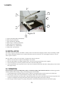
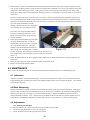
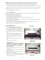
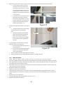
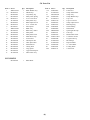
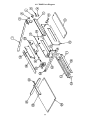
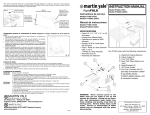
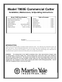
Model 7000E Commercial Cutter
Installation, Maintenance, & Operating Instructions
Model 7000E Specifications
Thickness Capacity (24# bond) . . . . . . . . .1 1/2"
Width Capacity (With Stop) . . . . . . . . . . . . . .12"
Length Capacity . . . . . . . . . . . . . . . . . . . . . . .12"
Cutting Method . . . . . . . . . . . . . . . . . . . . . .Lever
Clamping Method . . . . . . . . .Manual Handwheel
Dimensions . . . . . . . . . . . . . . .19" x 19" x 13 1/8"
Shipping Weight . . . . . . . . . . . . .48 lbs. (21.8 kg)
Table of Contents
1.0 Parts . . . . . . . . . . . . . . . . . . . . . . . . . Page
2.0 Installation . . . . . . . . . . . . . . . . . . . . . Page
3.0 Operation. . . . . . . . . . . . . . . . . . . . . . Page
4.0 Maintenance . . . . . . . . . . . . . . . . . . . Page
5.0 Parts List . . . . . . . . . . . . . . . . . . . . . . Page
6.0 Parts Diagram . . . . . . . . . . . . . . . . . . Page
7.0 Troubleshooting. . . . . . . . . . . . . . . . . Page
2
2
2
3
6
7
8
Serial # ____________________
INTRODUCTION
Thank you for selecting the Martin Yale Model 7000E Commercial Cutter. The 7000E has been performance-tested at the
Martin Yale factory. With recommended maintenance, the unit will provide years of trouble-free service. Please review
this publication in its entirety before attempting to operate your 7000E. Thorough understanding of this information will
help eliminate most operator-associated errors and ensure years of trouble-free performance.
WARNING!
The cutting blade of the 7000E is extremely sharp. Never place hands or fingers under
the cutting blade or into the cutting area. Serious bodily injury could result. Never allow children to
operate the 7000E unsupervised. The weight of the handle can cause the cutting blade to drop if the
spring-loaded safety arm is not fully engaged. Always make sure the spring-loaded safety arm is fully
engaged upon the completion of each cut by returning the handle to the full upright position. Test for
safety arm engagement before releasing the handle.
1.0 PARTS
F
A
G
B
C
E
Figure #1
D
A.
B.
C.
D.
E.
F.
G.
Paper Clamp Hand Wheel (M-S042004)
Back Gauge (W-O007042)
Paper Side Rail (W-O007028)
Back Gauge Lock Knob (M-S032041)
Blade Adjust Screw (M-S002052)
Blade Handle Assy. (WRA007053)
Safety Latch (W-O007019)
2.0 INSTALLATION
The 7000E is shipped completely assembled. Carefully remove the unit from the shipping container. Inspect for damage. If damage is found, immediately notify the carrier and then call Martin Yale for instructions. Save the shipping container in case the
cutter requires relocation.
Place the 7000E on a flat, level work surface. To prepare the cutter for operation:
1. Make sure all four feet are in place and touching the work surface.
2. Raise the blade handle to the fullest upright position. Be sure the spring-loaded safety arm is engaged.
3. Note the back gauge is secured in position on the side rail with the locking knob.
4. Note the measuring scale on top of the side rail. The scale is calibrated in both inch and metric readings that provide accurate
back gauge settings.
3.0 OPERATION
Do not attempt to operate the 7000E until you have read and thoroughly understand this manual. The following procedure
should be followed when loading, cutting, and unloading paper from the 7000E.
1. Lift the blade handle to the fullest upward position. Make sure the blade handle is locked in place by the safety latch.
2. Raise the paper clamp to the required height by rotating the clamp wheel counter-clockwise.
3. Loosen the locking knob on the back gauge. Align the back gauge to the point on the measuring scale that corresponds to the
required cut. Retighten the locking knob while pressing the back gauge firmly down on the wood top.
4. Place the paper stack through the cut opening and align the stack of material flush with the side rail and back gauge.
(2)
5.
Hold the stack in position with the left hand and with the right hand, lower the clamp by turning the clamp wheel clockwise. Proper clamping pressure is achieved when the clamp wheel is tightened 1/4 to 1/2 turn past where the clamp first
makes firm contact with the paper stack. Adding more pressure to the clamp may cause damage to the clamp, clamp
mount plate, and the roller bearing mechanism. Damage caused by over clamping is not covered under the 1-year limited warranty.
Excessive clamp pressure may cause the stock to be creased. The use of waste sheets above and below the stock to be
cut is a common protection method used to keep the finished stock from being marked or creased. If additional clamping pressure is required the blade may need to be sharpened. Continuing to cut with a dull blade may cause severe damage to the cutting mechanism or handle.
Damage caused by cutting with a dull blade is
not covered by the 1-year limited warranty.
6.
See section 4.4.2 for proper blade removal
and 4.2 for sharpening instructions or call
Martin Yale Customer Service @ 260-5630641 for assistance.
Firmly grasp the blade handle grip and release
the spring-loaded safety arm. Lower the
blade handle with an even stroke to complete
the cut action (See Figure #2). The blade
should cut cleanly through the last sheet but
not too deeply into the cutting stick. If it does
not, the cutting stick may need to be rotated to a fresh side (See 4.4.1).
This condition may occur if the blade is not level with the cutting stick
(See 4.3.2).
Return the blade handle to the fullest upward position. Make sure the blade handle is securely locked in place by the
safety latch.
Raise the paper clamp with counter clockwise rotation of the clamp wheel.
Remove all cut material from the 7000E.
Figure #2
7.
8.
9.
4.0 MAINTENANCE
Please refer to the diagram and parts list in the back of this instruction booklet to assist you in identifying the parts.
4.1 Lubrication
Whenever the blade is removed for sharpening, (see section 4.4.2) lubricate the clamp screw, the sides and slots of the
clamp mounting plate, and the lower portion of the handle assembly (where it pivots between the frame). Use a lithium
or petroleum base grease.
4.2 Blade Sharpening
Dulling of the blade is a natural occurrence and is determined primarily by the type of material being cut. Many paper
products today are made of re-cycled materials and can be very abrasive to the blade. If it becomes increasingly more
difficult to cut paper, the cut is rough, or if excessive clamp pressure is required to hold the stack, then it is time to
sharpen the blade (see section 4.4.2). Always keep a spare blade on hand to use while you send out the dull one to be
sharpened by a qualified blade sharpener or machine shop. Blade is to be ground to a 19° angle for resharpening.
4.3 Adjustments
4.3.1 Squaring The Side Rail
To square the side rail, use a square of known accuracy and follow this procedure.
1. Lower the cutting blade until it rests on the cutting stick.
2. Loosen the three screws on the right side of the side rail.
(3)
WARNING! The blade is sharp. Use extreme caution when working with or near the blade.
3. Place the short side of the square against the bottom of the blade and slide the square toward the side rail.
NOTE: Make sure the side rail is even with or slightly in front of the cut opening in the back plate.
Lower the clamp firmly onto the square, making sure it remains against the blade, and align the side rail to the long
edge of the square. Hold side rail in place and tighten 3 nuts on the bottom. Unclamp square and recheck squareness.
4. Follow the operating instructions and make a test cut. Cutting accuracy should be within 1/32" (.80 mm) and
squareness should be within 1/64" (.40 mm).
4.3.2 Leveling The Blade
Before leveling the cutting blade, loosen the lock nut and cut depth adjustment screw on the back of the machine (#5 in
parts diagram). To level the blade, follow this procedure.
1. Loosen the safety plate screws (See Figure #3).
2. Move the blade handle to the downward position.
3. Lift the handle up or down slightly until the blade is parallel and resting on the cutting stick.
4. Securely tighten the safety plate screws.
5. Following the operating instructions, test with strips placed at each end and center of the cutting stick. The blade
should make equal contact with each strip.
6. Hold the handle down and turn the cut depth adjustment screw clockwise until it contacts the blade. Turn the
adjusting screw 1/8 turn counterclockwise and tighten the lock nut.
NOTE: Blade should cut a maximum of 1/32" into the stick.
4.4 Parts Replacement
4.4.1 Rotating or Replacing The Cutting Stick
To rotate or replace the cutting stick, follow this procedure.
1. Raise the handle and make sure it is locked by the safety
lever in the upward position and raise the clamp.
2. Remove the two cutting stick retainers (#13 in parts diagram).
3. Slide the cutting stick out of the frame channel. (It may
be necessary to drive the stick from the channel.)
NOTE: The cutting stick may be rotated to all four
sides and turned end-for-end to make a total of eight
surfaces.
4. Slide the new cutting stick into the channel or rotate
90°.
5. Replace the cutting stick retainers.
1.
2.
3.
4.
4.4.2 Blade Removal
WARNING: The cutting blade is extremely sharp!
Never place hands or fingers under the cutting
blade or into the cutting area. Serious bodily
injury could result.
Lower the blade handle so that the cutting blade rests on the
cutting stick.
Turn the clamp handwheel clockwise so that the clamp rests
on the cutting deck.
Remove the front (small) wood deck by removing the two
phillips screws. (See Figure #3)
Remove the top cover from the frames by removing the
phillips screw near the handwheel and then sliding the cover toward the
handwheel, lifting up and off.
(4)
Safety Plate
Deck Screws
Figure #3
Figure #4
Step 5b
5.
6.
7.
Remove the safety plate by removing the two allen head screws that secure the safety plate to the frame.
a. Loosen, but do not remove, the four
allen head screws that hold the short
(#6 in parts list) and long (#15 in parts
list) spacers in the frames. Remove the
screw and spacer located at top center
between the front and back side frames
(#16 in parts list).
b. Loosen the three remaining lower front
frame allen head screws so that the
screw head is approximately 1/2” away
from the frame panel. (See Figure #4)
c. Slide the front frame away from the
Handle
machine approximately 1/2”.
Pin
Figure #5
Separate the handle from the blade. (See Figure
#5)
a. Grasp the handle and move the handle
and blade toward the loosened front
plate.
b. Move the handle back away from the
blade to free the handle pin from the
blade. The handle pin is shown in
figure #5 and is attached to the handle.
Lift the handle from the machine and
set aside.
Step 7
Using the blade tool (hook) remove the blade
from the machine. (See Figure #6)
a. Place the hook into the blade pin hole in
the cutting blade.
b. Lift the front end of the blade and slide
the blade out of the blade cam blocks
(#24 in parts diagram).
c. Secure the blade so that the cutting edge is not exposed.
d. Remove the blade cam roller from blade and save it for reinstalling the blade.
Figure #6
1.
2.
3.
4.
5.
6.
7.
8.
9.
4.4.3 Blade Installation
NOTE: Whenever a different blade is installed, you must level the blade after reassembly is complete.
Lubricate the blade assembly roller and install it on the blade pin (the pin that is permanently attached to the blade)
Insert the blade into the frame so that the blade assembly roller is between the blade cam blocks (See Figure #24 in
parts diagram for blade cam block location).
Insert the blade tool (hook) into the front blade pin hole and lower the blade into the frame so that the cutting edge
rests on the surface of the cutting stick.
Reattach the handle to the cutting blade.
Push the front plate toward the machine.
Tighten the long and short spacer screws (See #15 and #6 in parts diagram for long and short spacer location).
Install and tighten screw and spacer located at top center between the front and back frames (See #16 in parts dia-gram).
Install the top cover on the frame.
Install the blade safety plate and level blade (see section 4.3.2).
Install the front (small ) wood deck.
(5)
5.0 Parts List
Item. # Part #
1
WRA007053
1A
M-S043012
2
M-S043046
3
M-O007055
3A
M-S001157
4
W-A007050
5
M-S002052
5A
M-S007019
6
M-O007011
7
WRA007007
7A
M-O007016
8
W-O007022
8A
M-S003039
9
M-O007025
10
W-O007001
11
W-O007004
12
M-O007003
13
W-O007027
14
M-O007034
15
M-O007010
16
M-O007039
17
W-A007002
Qty.
1
1
1
1
1
1
1
1
1
1
1
1
2
1
1
2
1
2
1
1
1
1
Description
Blade Handle Assy.
Handle Grip
Vinyl Safety Tip
Safety Latch Spring
10-32 x 5/8 Screw
Safety Plate Assy.
Blade Adjust Screw
5/16 - 18 Hex Nut
Short Spacer
Blade Assy.
Blade Assy. Roller
Safety Plate
Safety Plate Screw
Small Wood Top
Front Frame
Thin Spacer Bar
Thick Spacer Bar
Stick Retainer
Cutting Stick
Long Spacer
Upper Frame Spacer
Main Frame Assy.
Item. #
17A
18
19
19A
20
20A
21
21A
21B
22
22A
23
24
24A
25
26
27
27A
28
28A
NOT SHOWN
M-O007080
1
Blade Hook
(6)
Part #
M-S030003
W-A007005
WRA007006
M-O007030
W-A007015
M-S001129
M-O007013
M-S010033
M-S008041
M-S042004
MRS042005
M-S043011
M-O007012
M-S63751051
M-O007024
W-O007042
W-O007028
M-O007032
M-S032041
M-S007111
Qty.
4
1
1
1
1
1
1
1
1
1
1
4
2
6
1
1
1
1
1
1
Description
Frame Feet
Clamp Mount Plate
Clamp Assy.
Clamp Rubber Strip
Top Cover
Top Cover Screw
Clamp Adjust Screw
Retaining Ring
Oilite Bushing
Hand Wheel
Spinning Knob/Clip
Tube Cap
Blade Roller Guide
1/4-20X1/2 Screws
Large Wood Top
Back Gauge
Paper Side Rail
13” Lexan Ruler
Locking Knob
5/16 Pal Nut
6.0 7000E Parts Diagram
(7)
7.0 TROUBLESHOOTING
7.1 Paper Not Completely Cut
Gradual wearing of the cutting stick is normal during machine operation. As a groove is formed in the stick by the cutting action of the blade, the blade may not completely cut through the bottom sheets of the stack. When this condition
occurs, rotate the cutting stick, or replace, if necessary. Also make sure the blade is level and is set for proper cutting
depth. See Section 4.3.2 and Section 4.4.1.
7.2 Excessive Pressure Necessary To Complete A Cut
Sharpen or replace the cutting blade according to instructions in Section 4.4.2.
NOTE: As an average, the cutting blade should be sharpened or replaced after eight cutting hours of 24# bond paper
(90g/m2). Cutting heavier or more abrasive material may necessitate more frequent sharpening or replacement of the
blade.
7.3 Cut Paper Is Out Of Square
Make sure the paper stack is correctly aligned to the side rail and back gauge. Also make sure the paper stack is correctly clamped with the paper clamp. See Section 4.3.1.
7.4 The Clamp Wheel Is Hard To Turn
Lubricate the wheel according to instructions in Section 4.1.
7.5 The Handle Is Hard To Move Up Or Down
Lubricate the handle according to instructions in Section 4.1.
7.6 The Blade Cuts On One Side But Not The Other
Level the blade according to instructions in Section 4.3.2.
7.7 The Blade Cuts In The Center Only
The cutting stick is bad. Follow instructions in Section 4.4.1.
251 Wedcor Avenue • Wabash, IN 46992
Phone (260) 563-0641 • Fax (260) 563-4575
Revised 9/16/02
M-S027057