1
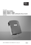
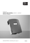
Contact
If you have technical problems, first contact your installer. The following information is required in
order to provide you with the necessary assistance:
•
•
•
•
•
Inverter device type
Inverter serial number
Type and number of PV modules connected
Blink code or display message of the inverter
Optional equipment (e.g. communication devices)
SMA Solar Technology AG
Sonnenallee 1
34266 Niestetal, Germany
www.SMA.de
PV Inverter
SUNNY MINI CENTRAL 4600A / 5000A / 6000A
User Manual
SMA Serviceline
Inverters: +49 561 9522 1499
Communication: +49 561 9522 2499
Fax: +49 561 9522 4699
E-Mail: [email protected]
Installer contact
Visual Inspection, Maintenance and Cleaning
Visual Inspection
Check the inverters and the cables for visible external damage. Contact your installer if you find any
defects. Do not perform any repair work yourself.
Maintenance and Cleaning
Ask your installer to check for proper inverter operation at regular intervals.
SMC46-60A-BEN101210 | IME-SMC50A_60A | Version 1.0
Explanation of Symbols
Symbols on the Inverter
Operation display.
Ground fault or varistor defective.
Please inform your installer.
An error has occurred. Please inform your installer immediately.
Tap to switch on the display light and switch to the next message.
Symbols on the Type Label
Beware of dangerous electrical voltage.
The inverter operates at high voltages. All electrical work
on the inverter may be carried out by qualified personnel
only.
Beware of hot surface.
The inverter can become hot during operation. Avoid contact during operation.
Observe the enclosed documentation.
EN
Glossary
AC
Abbreviation for "alternating current".
Asymmetric load
The difference between the power fed into the grid at the individual phase conductors. In Germany, it
is not permitted to exceed a nominal output of 5 kVA. In Italy, the nominal output is limited to 6 kVA.
DC
Abbreviation for "direct current".
Derating
A controlled reduction in performance, usually dependent on component temperatures. Compared
with the (also common) practice of completely shutting down the device, the effect on the external grid
is smaller with derating.
Electronic Solar Switch (ESS)
The Electronic Solar Switch is part of the inverter's DC disconnection unit. The
Electronic Solar Switch must be securely inserted into the bottom of the inverter and may
only be removed by qualified personnel.
Grid impedance
The grid impedance is a characteristic grid specification, which is determined both by the grid
infrastructure, and by the number of power suppliers and power consumers. If the supply for the
grid section should drop due to a grid shutdown of the preceding energy suppliers (medium-voltage
transformers), the grid impedance will change abruptly. In order to detect this and to prevent the
formation of an unwanted off-grid system, SMA Grid Guard monitors the grid impedance and
disconnects the inverter from the grid in the event of a sudden impedance variation.
The inverter must not be disposed of with the household waste.
Further disposal information can be found in the enclosed installation guide.
MPP (Maximum Power Point)
Operational point of the inverter, dependent on current / voltage of the PV generator. The actual
position of the MPP changes constantly, depending on the level of solar irradiation and the cell
temperature.
CE mark. The inverter complies with the requirements of the applicable EC
guidelines.
PV
Abbreviation for photovoltaics.
RAL quality mark for solar products. The inverter complies with the requirements of
ES
the German Institute for Quality Assurance
and Labeling.
SMA Power Balancer
The SMA Power Balancer is a standard feature of the Sunny Mini Central. The SMA Power Balancer
prevents the formation of an unwanted asymmetric load > 5 kVA (in Italy > 6 kVA) during three-phase
grid feed-in. To this effect, 3 Sunny Mini Centrals are each connected via a control line to a 3-phase
feeding unit.
Direct Current (DC)
Alternating Current (AC)
The inverter is protected against penetration by dust particles and water jets from
any angle.
The inverter has a transformer.
Varistor
The varistors protect the electronics in the inverter from atmospherically coupled energy peaks, such as
those that can occur when lightning strikes nearby.
Safety Precautions
Product Overview
Identification of the Sunny Mini Central by the type label
DANGER!
Electric shock caused by high voltage in the inverter.
Serial number
Air grills
Even when no external voltage is present, there can still be high voltages in the device.
The following work may be carried out by qualified personnel only:
• Electrical installation
• Repairs
• Modification
Enclosure lid
CAUTION!
Display
Risk of injury from touching the enclosure during operation.
Burns to the body.
• Only touch lid and display during operation.
LEDs
NOTICE!
Overvoltage in the inverter if yellow LED flashes 4 times.
Destruction of the inverter.
In operation
Ground fault or varistor defective
• Inform your installer immediately if the yellow LED starts
flashing and the following display message appears.
LED Modes
State
Display
Designation
Function
All LEDs are
on
Initialization
The inverter is initializing.
All LEDs are
off
Deactivation
The input voltage at the inverter is too low for grid
feeding.
Green LED is
permanently
on
Feeding
operation
Green LED is
flashing
Waiting, grid
monitoring
The inverter is monitoring the grid and is waiting for
the DC voltage to reach a certain level so that it can
start feeding the grid.
Stop
Interruption of operation.
Derating
Power limitation in the inverter.
Error
A ground fault has occurred, or one of the
thermally monitored varistors on the DC input side is
defective. Please inform your installer.
Red LED is
on
Disturbance
The inverter is operating in "Operation constantly
disabled" mode. This can have several causes.
Please inform your installer.
Yellow LED is
flashing
Disturbance
The inverter is indicating a disturbance. This can
have several causes. Please inform your installer.
Measuring Channels
If your inverter is equipped with a communication component, then numerous measuring channels
and messages can be transmitted for diagnosis.
dZac
Error
E-total
Event-Cnt
Fac
h-On
h-total
Iac
Ipv
Mode
Pac
Power On
Riso
Serial number
Vac
Vpv
Vpv-Setpoint
Operation
Description
Displays the currently active operating mode of the inverter which is set
under the operating parameter "PowerBalancer".
Grid impedance
Identification of the current disturbance / error.
Total amount of energy fed into the grid
Number of events that have occurred
Grid frequency
Total number of operating hours
Total number of operating hours for feeding operations
Grid current
DC current
Display of the current operating mode
Generated AC power
Total number of grid switch-ons
Insulation resistance of the PV system to the grid connection
Inverter serial number
Grid voltage
PV input voltage
PV target voltage
The display shows current values of your system. The displayed values
are updated every 5 seconds. The display is operated by tapping on it.
Tap once
The background illumination is switched on. After 2 minutes, the
illumination switches off automatically.
Tap again
The display switches to the next message.
Display messages
In operation
The inverter is feeding power into the public grid.
Yellow
LED is on
continuously
Measuring channel
Balancer
Disturbance
Upon error-free connection of the inverter to the grid, the following
notifications are shown in turn after approximately one minute. Each
notification appears for five seconds, then the cycle starts again.
Power produced on the current day
Operating condition
Current feed-in power
Voltage of the PV generator
Power produced so far
Total number of operating hours for feeding operations
Disturbance
In the event of a disturbance, the inverter will display the status
"Disturbance" and an error message. Please inform your installer.
The following notifications will be issued:
Power produced on the current day
Operating condition "Disturbance"
Operating condition
Error message
DC overvoltage
Measured value at time of disturbance
Current measured value (only displayed if a measured value is
responsible for the disturbance)
The DC input voltage connected to the inverter is too high.
Please inform your installer immediately.
Status Messages
Your inverter can be in various operating modes. These are displayed as status messages, which can
vary according to the method of communication.
Message
Balanced
Derating
Disturbance
Error
grid mon.
MPP
Off Grid
offset
Riso
Stop
V-Const
waiting
Description
The inverter has disconnected itself from the grid, or is limiting its output to
5 kVA over a 10 minute average. The inverter is part of a three-phase system
with two further inverters and equipped with the Power Balancer for preventing
asymmetric loads.
Overtemperature in the inverter. The inverter will reduce its output to prevent
overheating. To avoid unnecessary output losses, the design of the system
should be checked. Please inform your installer.
Disturbance. This message appears for safety reasons and prevents the inverter
from connecting to the grid. Please inform your installer.
An error has been detected. Please inform your installer.
Grid monitoring.
This display appears during the start phase, before the inverter is connected to
the grid, predominantly in the mornings and evenings when the solar irradiation
is low and after an error.
The inverter is operating in MPP mode. MPP is the standard display message
when operating under normal irradiation conditions.
The inverter is in "Island" mode. This mode is specially designed for operation in
an off-grid system.
Offset adjustment of measurement electronics.
Measurement of the insulation resistance of the PV system.
Interruption of operation.
Constant voltage operation.
The switch-on conditions are not (yet) fulfilled.