1
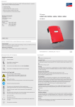
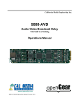
www.rmc-inst.com
Document ID: 502-5000A
1 WARNINGS/SAFETY ............................................................... 1
2 DESCRIPTION .......................................................................... 1
3 SYSTEM OVERVIEW ............................................................... 2
3.1
Figure 1 – Key Features RM502.........................................................................................................2
4 BATTERY INSTALLATION...................................................... 3
5 PC SOFTWARE SETUP........................................................... 3
6 COMMUNICATIONS DRIVER INSTALLATION AND CABLE
HOOKUP......................................................................................... 3
7 SETUP ....................................................................................... 4
8 RM502 PROGRAMMING ......................................................... 4
OPERATION ................................................................................... 4
9 UPLOADING COLLECTED DATA .......................................... 5
10
PLOTTING DATA .................................................................. 6
10.1
Figure 2 – Typical Plot ........................................................................................................................6
10.2
Buttons and Program Functions.......................................................................................................7
10.3
Saving Data ...........................................................................................................................................8
10.4
Exporting Data......................................................................................................................................8
11
SPECIFICATIONS ................................................................. 9
12
WARRANTY ......................................................................... 10
i
1 Warnings/Safety
WARNING: USE ONLY THE RECOMMENDED 2032
LITHIUM BATTERY FOR THIS UNIT.
WARNING: USE ONLY SUPPLIED CABLING FOR
CONNECTING TO THIS UNIT.
2 Description
The RM502 is a data-logger designed to gather information on
temperature, humidity, tilt, and shock using its internal sensors.
An optional sensor assembly is used to measure external
temperatures. The RM502 stores up to 3270 records in nonvolatile memory. Each record consists of a temperature, humidity,
x,y,z shock readings, tilt status, and an optional external
measurement. As a factory installed option the memory may be
doubled to over 6400 records. The RM502 will operate for up to
two months on a single battery.
1
3 System Overview
The RM502 kit contents includes RM502 Unit, 1 2032 lithium
battery, USB communication cable, and a User Manual. Figure 1
below shows the RM502 and key interfaces.
Humidity Alarm
(Green LED)
Tilt Alarm
(Yellow LED)
Cold Temperature
Alarm
(Blue LED)
Shock Alarm
(Yellow LED)
HighTemperature
Alarm
(Red LED)
Communications
Jack
Acquisition (Green LED)
Flashes when acquiring
data.
Note: Deactivated if one or
more alarm LEDs flash.
Battery Access
Remove screw and
cover to access
battery 2032
Delay (Red LED)
Flashes when unit is
in delay mode before
acquisition.
3.1 Figure 1 – Key Features RM502
The RM502 is connected to a PC with the auxiliary cable included
with the kit. A disc is included in the kit containing a PC based
Windows program that allows the user to program the operating
parameters of the RM502 and download and display the collected
data.
2
4 Battery Installation
Remove the single screw holding the circular cover of the RM502
to access the battery. The battery holder is on the circuit board.
Install the 2032 lithium battery in the holder noting the correct
polarity.
IMPORTANT: OBSERVE BATTERY POLARITY DURING
INSTALLATION.
After battery installation, the RM502 is now active and ready for
programming.
5 PC Software Setup
Loading the RM502 Software:
Place the CD into the PC. Enter the “Start” Menu and activate
control panel. Double click on “Add/Remove Software”.Hit the
“Install” button and follow the instructions with the installation
program. Start the program.
6 Communications Driver Installation and Cable Hookup
Go to the Windows “Start” and then to folder “RMC/RM500 PC
Software. Run “Driver.exe” which will automatically install the
required drivers for XP, Vista, and Windows 7 systems.
Plug the USB cable into the computer. The communications cable
and associated software create a virtual communications port
used by the software. Additional information on driver installation
can be found at the web site www.FTDICHIP.com.
3
7 Setup
Enter the ‘Setup’ window to configure communications and
desired temperature units. Use the “Find” button in “Setup” to
automatically locate the proper serial port. This process only
needs to be completed once when the communications cable is
installed on a computer.
8 RM502 Programming
Enter “Program” from the main menu. First erase any previous
data before programming. Warning! Hitting the “ERASE” button
at this point will permanently remove any collected data. If you
have previous data you want to save upload it first . See the
Upload Collected Data Section below.
Select the acquisition rate. Keep in mind that the faster you
acquire data, the faster that the memory in the RM502 will be
used up. The dialog will calculate the available run time. Note: For
very long runtimes the life of the battery governs the useful
duration of the data logging. After making your selections, Hit the
'Program' button.
Operation
As soon as the communications cable is disconnected from the
RM502, the device will start collecting data per the programmed
parameters. Alarms will be active immediately unless a delay was
set. During the delay a red delay will flash on the unit to show the
unit is in delay mode. When in delay mode no acquisitions will
occur and the alarms will not be set. This feature allows the user
to position the device without inadvertently triggering an alarm.
When actively acquiring data the unit will flash a green light
unless an alarm has occurred. Data will be collected and stored
in non-volatile memory that can be retrieved later.
4
Alarm lights on the top of the unit will flash briefly every four
seconds when one of the programmable limits for each alarm has
been exceed. Alarms are lit with color coded LEDs as shown in
Figure 3.1
Alarm status does not affect acquiring data in any way.
9 Uploading Collected Data
After data has been collected by the RM502, data may be
collected by connecting the USB cable up to the communications
port of the RM502 as with programming.
Clicking on the ‘Upload’ button will start the upload process. This
may take several minutes depending upon the amount of data. A
status bar will give an indication of the download. If the
connection is lost for any reason, the data may be uploaded again
by clicking on the “Upload” button. When complete the data will
be plotted for review.
5
10 Plotting Data
When data is retrieved from the RM502 or read from a previously
saved file, a plot similar to figure 2 will appear with a Plotting
Toolbar, a Plotting Data Status Bar, and a plot representing the
collected data.
10.1 Figure 2 – Typical Plot
6
10.2 Buttons and Program Functions
Icon Name
Open
Export
Save
Print
Setup
Program
Upload
Internal
Temperature
Humidity
Shock –XShock –YShock –ZAmbient Light
Tilt
External
Temperature
Help
Move Left
Move Right
Jump Left
Description
Opens data files
Exports file into spreadsheet readable
*.CSV files
Saves data files
Prints the current plot
Sets up the communication link and
set degrees F / C
Programs the RM502 sampling time,
sets current time, thresholds, etc.
Uploads data from the RM502 to the
PC
Displays the Internal Temperature plot
Displays the Humidity plot
Displays –X- Axis shock.
Displays –Y- Axis shock.
Displays –Z- Axis shock.
Displays ambient light changes.
Displays the tilt plot.
Displays the external temperature.
Disabled if an ext. sensor not used.
Displays Help
Moves the cursor one data point to the
left.
Moves the cursor one data point to the
right.
Jumps the cursor 1/10 of the total time
7
Jump Right
Expand
Delta
Advance
Channel
Zoom
Overlay
Channels
to the left.
Jumps the cursor 1/10 of the total time
to the right.
Expands the plot to the full data
range.
Drops the delta cursor at the current
cursor location
Move to a new channel
Set zoom mode. Use the left mouse
button and hold to zoom in on data.
Overlays the other channels on the
same plot.
10.3 Saving Data
Save the data using the “Save” command in the File menu before
uploading more data.
10.4 Exporting Data
Data that has been uploaded or saved may be exported to
comma separated file that can be read by Excel® or other
spreadsheet programs. The files are saved with a *.CSV
extension.
8
11 Specifications
RM502 Datalogger
Size: 2.5” x 3” x 0.5”
Weight: 2 oz.
Power Input: 2032 Lithium battery
Operating Temperature: -30°C to 70°C
Temperature Accuracy: +/-1°
Temperature Resolution: 0.1°C
Ambient Light: 10 – 1000 Lux
Humidity: 5% - 90%
Tilt: 6 position
Shock: 3 Axis 0-8 g
Interface: Custom USB Cable
9
12 Warranty
Remote Measurements & Controls Incorporated (R.M.C.)
warrants this product against defects in material or workmanship,
as follows: For a period of 90 days from date of purchase R.M.C.
repair or replace, at its option, any defective component or system
at no charge. This warranty does not cover damage caused by
accident, misuse, abuse, or in an environment inconsistent with
the specification of the product. R.M.C. shall in no event be liable
for the loss of use of this or any other product or damages to any
piece of equipment. R.M.C. reserves the right to make changes
in design and or improvements in its products without the
obligation to incorporate the changes or improvements in any of
its previously manufactured products. REPAIR OR
REPLACEMENT AS PROVIDED UNDER THIS WARRANTY IS
THE EXCLUSIVE REMEDY OF THE CONSUMER. R.M.C.
SHALL NOT BE LIABLE FOR ANY INCIDENTAL OR
CONSEQUENTIAL DAMAGES OR FOR BREACH OF ANY
EXPRESS OR IMPLIED WARRANTY ON THIS PRODUCT.
EXCEPT TO THE EXTENT PROHIBITED BY APPLICABLE
LAW, ANY IMPLIED WARRANTY OF MERCHANTABILITY OR
FITNESS FOR A PARTICULAR PURPOSE ON THIS PRODUCT
IS LIMITED IN DURATION TO THE DURATION OF THIS
WARRANTY. Some states do not allow the exclusion of incidental
or consequential damages, or allow limitations on how long an
implied warranty lasts, so the above limitations or exclusion may
not apply to you. This warranty gives you specific legal rights,
and you may also have other rights which vary from state to state.
10