1
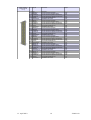
DSUB37 female
Pin
19
37
18
36
17
35
16
34
15
33
14
32
13
31
12
30
11
29
10
28
9
27
8
26
7
25
6
24
5
23
4
22
3
21
2
20
1
Left (U6..U11)
NC
IMON+6
IMON-6
UMON+6
UMON-6
XON6
XON-RET6
IMON+7
IMON-7
UMON+7
UMON-7
XON7
XON-RET7
IMON+8
IMON-8
UMON+8
UMON-8
XON8
XON-RET8
IMON+9
IMON-9
UMON+9
UMON-9
XON9
XON-RET9
IMON+10
IMON-10
UMON+10
UMON-10
XON10
XON-RET10
MON+11
IMON-11
UMON+11
UMON-11
XON11
XON-RET11
Right (U0..U5)
NC
IMON+0
IMON-0
UMON+0
UMON-0
XON0
XON-RET0
IMON+1
IMON-1
UMON+1
UMON-1
XON1
XON-RET1
IMON+2
IMON-2
UMON+2
UMON-2
XON2
XON-RET2
IMON+3
IMON-3
UMON+3
UMON-3
XON3
XON-RET3
IMON+4
IMON-4
UMON+4
UMON-4
XON4
XON-RET4
MON+5
IMON-5
UMON+5
UMON-5
XON5
XON-RET5
Comment
reserved
Current monitoring signal
Current monitoring signal return
Connected to the positive sense lines
Connected to the negative sense lines
Combined ON/Status line
ON/Status line return
Current monitoring signal
Current monitoring signal return
Connected to the positive sense lines
Connected to the negative sense lines
Combined ON/Status line
ON/Status line return
Current monitoring signal
Current monitoring signal return
Connected to the positive sense lines
Connected to the negative sense lines
Combined ON/Status line
ON/Status line return
Current monitoring signal
Current monitoring signal return
Connected to the positive sense lines
Connected to the negative sense lines
Combined ON/Status line
ON/Status line return
Current monitoring signal
Current monitoring signal return
Connected to the positive sense lines
Connected to the negative sense lines
Combined ON/Status line
ON/Status line return
Current monitoring signal
Current monitoring signal return
Connected to the positive sense lines
Connected to the negative sense lines
Combined ON/Status line
ON/Status line return
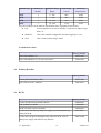
Table 7: Remote Control Connector Pin Assignment
3.7
Power Output and Sense Connections
The low voltage DC output at the rear side of the power supply is provided by 4 mm sockets
(Figure 3.3: Power Box Rear Side). The channels are arranged from left to right starting
with U0. Positive output is up and negative output is down.
The sense lines are routed to three DSUB connectors (four channels each).
DSUB9 male
Pin
1
6
2
7
3
8
4
9
5
Left Connector (U0..U3)
U0 Sense +
U0 Sense U1 Sense +
U1 Sense U2 Sense +
U2 Sense U3 Sense +
U3 Sense not connected
Middle Connector (U4..U7)
U4 Sense +
U4 Sense U5 Sense +
U5 Sense U6 Sense +
U6 Sense U7 Sense +
U7 Sense not connected
Right Connector (U8..U11)
U8 Sense +
U8 Sense U9 Sense +
U9 Sense U10 Sense +
U10 Sense U11 Sense +
U11 Sense not connected
Table 8: Sense Connector Pin Assignment
13. April 2010
11
*00691.A0