1
Introduction
Thank you for purchasing the SVR430.
This user manual is for the SVR 430. The term "unit" always refers to the SVR 430. We recommend users
who install and operate the unit to thoroughly read this manual and other reference manuals indicated in
this manual before installation and operation.
This specification is subject to changes without prior notice to incorporate improvements in the performance of the unit.
Warranty and Disclaimer
The manufacturer does not assume any responsibilities related to the sales of the unit and does not
endorse any third party to represent the manufacturer in any way. The warranty does not apply to malfunctions of the unit or its parts resulting from any accident, negligence, misuse, or misapplication. Also,
the warranty does not include accessories or components that the manufacturer does not supply.
The warranty is valid for the one year from the date of purchase. However, the malfunctions listed below
are not covered by the warranty even during the warranty period. Repair services for the malfunctions
below will be available, but with applicable charges.
• If any malfunctions occur due to carelessness of the user;
• If a user disassembles or replaces any parts of the unit without permission;
• If any power other than the rated power is connected to the unit;
• If malfunctions occur due to natural disaster (fire, flood, tidal wave, etc.); or,
• If consumable parts/items are to be replaced;
The warranty specified herein is only for the units delivered.
Consumers will be charged for examination and repairs after the expiration of the warranty period (one
year). A fee will be assessed for repairs or examination except within the scope of warranty specified
herein even during the warranty period.
For out-of-warranty services, please contact your local vendor or service center.
Be sure to contact your local vendor for installation, repair, or replacement of the HDD. Any work by
unauthorized personnel will not be covered by warranty.
Set the HDD to the Slave Mode for the jumper.
1
Warning Marks
Warnings and Cautions – the marks that give warning to users in this manual indicate different levels of
importance. These marks are classified by the level and potentiality of risk.
It is strongly recommended for users to completely understand these marks before using the unit.
Warning
This warning is given where carrying out an instruction can cause serious risk of injury or
death if the unit is not properly handled or operated. It indicates the operations requiring
the highest attention in handling or operating the unit.
Caution
This warning is given where carrying out an instruction can cause risk of damage to the
equipment or minor injury if the unit is not properly handled or operated.It indicates the
operations requiring the proper attention in handling or operating the unit.
Notes
2
It provides references or information that may be helpful to users in operating the unit.
Contents
1 Safety Cautions
6
2 Overview
8
2.1 Features . . . . . . . . . . . . . . . . . . . . . . . . . . . . . . . . . . . . . . . . . . . . .
8
2.2 Configuration . . . . . . . . . . . . . . . . . . . . . . . . . . . . . . . . . . . . . . . . . .
10
2.3 Names and Functions of Each Part
. . . . . . . . . . . . . . . . . . . . . . . . . . . . . .
11
2.3.1 Control Panel on the front . . . . . . . . . . . . . . . . . . . . . . . . . . . . . . . .
11
2.3.2 Rear Connection Terminals . . . . . . . . . . . . . . . . . . . . . . . . . . . . . . .
13
2.3.3 Remote Controller . . . . . . . . . . . . . . . . . . . . . . . . . . . . . . . . . . . .
14
2.4 Unit Specification . . . . . . . . . . . . . . . . . . . . . . . . . . . . . . . . . . . . . . . .
15
3 How to Install
19
3.1 How to Connect All Parts . . . . . . . . . . . . . . . . . . . . . . . . . . . . . . . . . . . .
19
3.2 Detailed Connection . . . . . . . . . . . . . . . . . . . . . . . . . . . . . . . . . . . . . . .
20
3.2.1 How to Install Removable HDD Rack . . . . . . . . . . . . . . . . . . . . . . . . . .
20
3.2.2 Rack Mount . . . . . . . . . . . . . . . . . . . . . . . . . . . . . . . . . . . . . . .
20
3.2.3 Power . . . . . . . . . . . . . . . . . . . . . . . . . . . . . . . . . . . . . . . . . .
21
3.2.4 Camera . . . . . . . . . . . . . . . . . . . . . . . . . . . . . . . . . . . . . . . . .
21
3.2.5 Audio Connection . . . . . . . . . . . . . . . . . . . . . . . . . . . . . . . . . . . .
22
3.2.6 Monitor . . . . . . . . . . . . . . . . . . . . . . . . . . . . . . . . . . . . . . . . . .
23
3.2.7 External Connector . . . . . . . . . . . . . . . . . . . . . . . . . . . . . . . . . . .
23
4 How to Set
28
4.1 Menu Configuration . . . . . . . . . . . . . . . . . . . . . . . . . . . . . . . . . . . . . . .
28
4.2 Default Setup . . . . . . . . . . . . . . . . . . . . . . . . . . . . . . . . . . . . . . . . . .
30
4.3 How to Use Jog/Shuttle . . . . . . . . . . . . . . . . . . . . . . . . . . . . . . . . . . . . .
33
4.4 Menu Screen Setup . . . . . . . . . . . . . . . . . . . . . . . . . . . . . . . . . . . . . . .
34
4.5 Screen Setup . . . . . . . . . . . . . . . . . . . . . . . . . . . . . . . . . . . . . . . . . .
35
4.5.1 CH1 ∼ CH4 . . . . . . . . . . . . . . . . . . . . . . . . . . . . . . . . . . . . . . .
35
4.5.2 SEQUENCING
. . . . . . . . . . . . . . . . . . . . . . . . . . . . . . . . . . . . .
37
4.5.3 STATUS . . . . . . . . . . . . . . . . . . . . . . . . . . . . . . . . . . . . . . . . .
37
4.6 Record Setup . . . . . . . . . . . . . . . . . . . . . . . . . . . . . . . . . . . . . . . . . .
38
4.6.1 REPEAT . . . . . . . . . . . . . . . . . . . . . . . . . . . . . . . . . . . . . . . . .
39
4.6.2 CURRENT . . . . . . . . . . . . . . . . . . . . . . . . . . . . . . . . . . . . . . . .
40
4.6.3 General Recording . . . . . . . . . . . . . . . . . . . . . . . . . . . . . . . . . . .
41
4.6.4 SCHEDULE . . . . . . . . . . . . . . . . . . . . . . . . . . . . . . . . . . . . . . .
42
4.6.5 EVENT . . . . . . . . . . . . . . . . . . . . . . . . . . . . . . . . . . . . . . . . . .
45
4.7 Event Setup . . . . . . . . . . . . . . . . . . . . . . . . . . . . . . . . . . . . . . . . . . .
46
. . . . . . . . . . . . . . . . . . . . . . . . . . . . . . . . . . . . . . . . .
46
4.7.2 MD . . . . . . . . . . . . . . . . . . . . . . . . . . . . . . . . . . . . . . . . . . . .
47
4.7.3 SENSOR . . . . . . . . . . . . . . . . . . . . . . . . . . . . . . . . . . . . . . . . .
49
4.7.4 RELAY . . . . . . . . . . . . . . . . . . . . . . . . . . . . . . . . . . . . . . . . . .
49
4.7.5 DISPLAY . . . . . . . . . . . . . . . . . . . . . . . . . . . . . . . . . . . . . . . . .
50
4.7.1 CHECK
3
4.8 PTZ Setup . . . . . . . . . . . . . . . . . . . . . . . . . . . . . . . . . . . . . . . . . . . .
51
4.9 Communication . . . . . . . . . . . . . . . . . . . . . . . . . . . . . . . . . . . . . . . . .
52
. . . . . . . . . . . . . . . . . . . . . . . . . . . . . . . . . . . . . . .
53
4.9.2 RS–232(Standby terminal) . . . . . . . . . . . . . . . . . . . . . . . . . . . . . . .
54
4.9.3 RS–422/485 . . . . . . . . . . . . . . . . . . . . . . . . . . . . . . . . . . . . . . .
54
4.9.4 E-Mail . . . . . . . . . . . . . . . . . . . . . . . . . . . . . . . . . . . . . . . . . .
55
4.10 System Setup . . . . . . . . . . . . . . . . . . . . . . . . . . . . . . . . . . . . . . . . . .
56
4.10.1 HDD . . . . . . . . . . . . . . . . . . . . . . . . . . . . . . . . . . . . . . . . . . .
56
4.10.2 PASSWORDS . . . . . . . . . . . . . . . . . . . . . . . . . . . . . . . . . . . . . .
57
4.10.3 DATE SETUP . . . . . . . . . . . . . . . . . . . . . . . . . . . . . . . . . . . . . .
59
4.10.4 ETC . . . . . . . . . . . . . . . . . . . . . . . . . . . . . . . . . . . . . . . . . . .
60
4.11 Exit Menu . . . . . . . . . . . . . . . . . . . . . . . . . . . . . . . . . . . . . . . . . . . .
62
4.9.1 NETWORK
5 Operations
5.1 Preliminary Checks before Starting Operation . . . . . . . . . . . . . . . . . . . . . . . . .
63
5.2 Power Connection . . . . . . . . . . . . . . . . . . . . . . . . . . . . . . . . . . . . . . . .
63
5.3 Live Video Screen . . . . . . . . . . . . . . . . . . . . . . . . . . . . . . . . . . . . . . . .
63
5.3.1 Individual Channel and Split Screen Display . . . . . . . . . . . . . . . . . . . . . .
64
5.3.2 Auto Screen Display Switching . . . . . . . . . . . . . . . . . . . . . . . . . . . . .
64
5.4 Recording . . . . . . . . . . . . . . . . . . . . . . . . . . . . . . . . . . . . . . . . . . . .
65
5.4.1 General Recording . . . . . . . . . . . . . . . . . . . . . . . . . . . . . . . . . . .
65
5.4.2 Scheduled Recording . . . . . . . . . . . . . . . . . . . . . . . . . . . . . . . . . .
65
5.5 Recorded Video Search . . . . . . . . . . . . . . . . . . . . . . . . . . . . . . . . . . . . .
66
5.5.1 Recorded Time Search . . . . . . . . . . . . . . . . . . . . . . . . . . . . . . . . .
66
5.5.2 Event Search . . . . . . . . . . . . . . . . . . . . . . . . . . . . . . . . . . . . . .
67
5.5.3 Log File Search . . . . . . . . . . . . . . . . . . . . . . . . . . . . . . . . . . . . .
68
5.6 Recorded File Playback . . . . . . . . . . . . . . . . . . . . . . . . . . . . . . . . . . . . .
68
5.6.1 Jog Dial/Shuttle Ring . . . . . . . . . . . . . . . . . . . . . . . . . . . . . . . . . .
69
5.7 Live/Playback Screen Switching . . . . . . . . . . . . . . . . . . . . . . . . . . . . . . . .
69
5.8 Digital Zoom . . . . . . . . . . . . . . . . . . . . . . . . . . . . . . . . . . . . . . . . . . .
70
5.9 Copy . . . . . . . . . . . . . . . . . . . . . . . . . . . . . . . . . . . . . . . . . . . . . . .
70
5.10 PTZ
. . . . . . . . . . . . . . . . . . . . . . . . . . . . . . . . . . . . . . . . . . . . . . .
71
5.10.1 PTZ Adjustment . . . . . . . . . . . . . . . . . . . . . . . . . . . . . . . . . . . . .
72
5.10.2 Preset . . . . . . . . . . . . . . . . . . . . . . . . . . . . . . . . . . . . . . . . . .
72
5.10.3 Use Preset . . . . . . . . . . . . . . . . . . . . . . . . . . . . . . . . . . . . . . . .
72
5.11 QUICK SET . . . . . . . . . . . . . . . . . . . . . . . . . . . . . . . . . . . . . . . . . . .
73
5.12 PIP . . . . . . . . . . . . . . . . . . . . . . . . . . . . . . . . . . . . . . . . . . . . . . . .
73
5.13 System Information . . . . . . . . . . . . . . . . . . . . . . . . . . . . . . . . . . . . . . .
74
5.14 Alarm Reset . . . . . . . . . . . . . . . . . . . . . . . . . . . . . . . . . . . . . . . . . . .
74
6 Network Viewer Program
4
63
75
6.1 Network Viewer Program Installation . . . . . . . . . . . . . . . . . . . . . . . . . . . . . .
75
6.1.1 System Requirement . . . . . . . . . . . . . . . . . . . . . . . . . . . . . . . . . .
75
6.1.2 Network Environment . . . . . . . . . . . . . . . . . . . . . . . . . . . . . . . . . .
75
6.1.3 Program Installation . . . . . . . . . . . . . . . . . . . . . . . . . . . . . . . . . . .
76
6.2 Select: Access to the Unit . . . . . . . . . . . . . . . . . . . . . . . . . . . . . . . . . . . .
76
6.3 Arrange: Screen Arrangement . . . . . . . . . . . . . . . . . . . . . . . . . . . . . . . . .
77
6.4 Control Panel . . . . . . . . . . . . . . . . . . . . . . . . . . . . . . . . . . . . . . . . . .
78
6.4.1 Search Control . . . . . . . . . . . . . . . . . . . . . . . . . . . . . . . . . . . . . .
79
6.4.2 Channel Control . . . . . . . . . . . . . . . . . . . . . . . . . . . . . . . . . . . . .
81
6.4.3 Pan/Tilt Control . . . . . . . . . . . . . . . . . . . . . . . . . . . . . . . . . . . . .
82
7 SVR-430 CD-Backup VIEWER
83
7.1 CD-Backup Viewer Program Installation . . . . . . . . . . . . . . . . . . . . . . . . . . . .
83
7.1.1 System Specification . . . . . . . . . . . . . . . . . . . . . . . . . . . . . . . . . .
83
7.1.2 Program Start-up . . . . . . . . . . . . . . . . . . . . . . . . . . . . . . . . . . . .
83
7.2 Functions of Icons . . . . . . . . . . . . . . . . . . . . . . . . . . . . . . . . . . . . . . . .
84
7.3 Play . . . . . . . . . . . . . . . . . . . . . . . . . . . . . . . . . . . . . . . . . . . . . . .
84
7.4 Save . . . . . . . . . . . . . . . . . . . . . . . . . . . . . . . . . . . . . . . . . . . . . . .
86
8 Troubleshooting
87
5
Chapter 1
Safety Cautions
Warning
• Before Installation
– On the rear of the unit, ensure accurate setting of supply voltage (AC 115V/AC230V) prior to
power connection (See Paragraph 3.2.3 – Power Changeover Switch Setting ).
– Disconnect the power before installation.
– Do not install the unit in humid locations. It may result in a risk of electrical shock or fire.
– This unit must be properly grounded to prevent any risks of electrical shock.
• During Operation
– Do not open the cover of the unit unless you are an authorized installer. It may result in a risk of
electric shock.
– Operate the unit within the allowable limits of temperature and humidity.
– Do not connect several power lines to one outlet at the same time. It may result in a risk of fire.
– Do not put heavy objects or containers of water or other liquid on the unit. It may result in failure
of the unit.
– Do not use near flammable gases or combustible dusts such as propane or gasoline. It may
result in a risk of explosion or fire.
– Do not touch power plug with wet hands. It may result in a risk of electrical shock.
– Do not put your hands into the insertion hole of the hard rack. It may result in a risk of personal
injury.
– Random replacement of built-in lithium battery by other types of batteries may cause explosion.
Thus, the battery shall be replaced by the same battery. And the used batteries shall be disposed
carefully because they can cause environment pollutions.
– Be careful to prevent any electrified materials from being absorbed through the ventilation grilles
of the cooling fan.
– Do not forcefully drag a power cord. It may result in a risk of electric shock or fire if a cord is
damaged.
• Disassembly and Cleaning
– Do not disassemble, repair, or alter the unit without authorization. It may result in a risk of failure,
electrical shock, and personal injury.
– Do not use water, thinners, or organic solvents for cleaning the unit surface. It may result in a risk
of failure or electrical shock. For cleaning the unit surface, use a dry cloth.
6
Cautions
• During Installation
– Install the unit such that a minimum of 15cm space exists between the ventilation grills of the
cooling fan and any wall or surface in order to ensure smooth heat release.
– Be sure to install the unit on the flat surface. An unsecured fall may result in a risk of failure or
personal injury.
– Keep away from the direct sunlight or excessive heats. It may result in a risk of distortion or failure
of the unit.
– If a camera is installed during the DVR recording, the images of other channels can be broken.
We recommend to start recording after installation of a camera.
• During Installation
– Be cautious not to shock or shake the unit while moving or operating the unit.
– Do not move the unit while it is in use.
– Do not apply strong force or throw the unit.
– We recommend using SAMSUNG/Maxtor HDD(5400RPM / EIDE Type).If you add other HDDs,
the system may cause abnormal operations. Thus, please contact your local vendor before
adding a HDD. The unauthorized addition of HDD shall not be subject to the warranty.
FCC Compliance Statement
• Caution: Any changes or modifications in construction of this device which are not expressly approved the party responsible for compliance could void the user’s authority to operate the
equipment.
• NOTE: This equipment has been tested and found to comply with the limits for a Class A digital device, pursuant to part 15 of the FCC Rules. These limits are designed to provide reasonable
protection against harmful interference when the equipment is operated in a commercial environment. This equipment generates, uses, and can radiate radio frequency energy and, if not
installed and used in accordance with the instruction manual, may cause harmful interference
to radio communications, Operation of this equipment in a residential area is likely to cause
harmful interference in which case the user will be required to correct the interference at his
own expense.
7
Chapter 2
Overview
The Samsung SVR 430 is a digital video recorder designed to be used as the security device in small
shops, convenience stores, banks, ATMs, etc. It is a stand-alone device, securing system performance
and safety.
The Samsung SVR 430 saves video images on the HDD instead of on videotapes. Then, it can save
quality images even for repetitive recording and facilitates data search as recording and playing video
data in the digital file format.
Moreover, the Samsung SVR 430 is a user-oriented digital unit with high quality moving pictures and high
capacity storage media. It has a variety of functions such as motion detects, PTZ (Pan, Tilt and Zoom)
control, password setting, real-time voice data storage, and up to 1,000 event lists and log file storage.
The SVR 430 also simultaneously and perfectly implements recording/playback and backup functions.
2.1 Features
Monitoring Screen
The Samsung SVR 430 implements high quality live images every channel and provides a wide range of
monitoring screens.
• Real-Time Full Screen and Split Display Mode
• Auto Screen Display Switching(AUTO)
• Easy switching from a playback screen to a monitoring screen(LIVE/PB)
• Pan, Tilt, Digital Zoom, PIP (Picture in Picture)
Recording
The Samsung SVR 430 can save up to 120 frames per second. It also records events on an event list
as well as provides the pre-event recording function that records images up to 5 seconds before the
occurrence of events.
• Simultaneous execution of four functions: recording, playback, backup, and networking
• Convenient setting of recording resolution by channel.
• Up to 3 kinds of image quality setting available.
• Simple setting of the scope of motion detection.
• Recording setting up to 120 frames per seconds.(based on 320×240)
• Manual and reservation recording.
• Event recording using external alarms and motion detection function.
• Video loss detection.
• Creating event lists for external alarms and motion detection.
• Recording images up to 5 seconds before the occurrence of events.
8
Playback
Fast search and playback using digital Jog/Shuttle.
• Playback by time, date, and channel.
• Still image search.
• Convenient search using a remote control and Jog/Shuttle.
• Digital zoom on a playback screen.
Storage Media
Built-in HDD is the basic memory supply. Users can save images on removable HDD, CD–RW, or USB
memory by options.
• Basic Memory Supply: Built-in HDD(Capacity: Option)
• A variety of backup media: Removable HDD, CD–RW, USB memory.
Network
The Samsung SVR 430 supports a wide range of networks such as LAN and xDSL. The user can also
easily operate and manage main functions of the unit from a remote place using the exclusive PC viewer.
• Live image view from a remote location available (full or quad screen mode selectable).
• Search and playback by time or event from a remote location.
• 10Mbps Ethernet/xDSL supported
Others
• Simple firmware upgrade using USB memory.
• Up to 4 channel voice recording in real time – selectable.
• Convenient control of 16 units using one remote control.
• VGA output supported (option).
• Languages for menus – selectable.
9
2.2 Configuration
The SVR 430 package contains the main unit and its components as specified below. When you purchase
the unit, please check to ensure the components specified below are included. If any components are
missing, please contact your local vendor.
10
2.3 Names and Functions of Each Part
2.3.1
Control Panel on the front
■ Power and Removable HDD Sector
Button Names
Functions
1
O
Power Button
Power On/Off.
2
O
Removable HDD Rack /
Installs the removable HDD rack or CD-RW for backup. Functional Button
CD–RW
Page.
■ Functional Button
Button Names
Functions
1
O
ESC
Goes to the previous menu.
2
O
MENU | N
Sets the menu, moves the cursor upward, and pages.
3
O
STATUS
Displays the system setting status.
4
O
COPY
Displays the copy menu. Saves the data at the preset time in R-HDD or
CD-RW. Saves the pause images in the Memory Stick via USB.
5
O
AR.RST | J | (FOCUS)
Adjusts the focus of PTZ camera, releases alarms when the alarms are
occurred and moves the cursors and pages to the left and right.
6
O
ENTER | (AF)
Uses for automatic focusing in the PTZ mode and selection of values.
7
O
PTZ | I
Selects the PTZ mode, moves the cursor to the right, and pages.
8
O
LIVE/PB
Switches from a live screen to a playback screen.
9
O
Adjusts the Pan in the PTZ mode and reduces values.
| (PAN)
10 H | (TILT)
O
Moves the cursor downward and pages and adjusts the Tilt in the PTZ
mode.
11 PIP |
O
| (ZOOM)
Selects the PIP function, increases values, and adjusts the Zoom in the PTZ
mode.
12 AUTO
O
Starts or releases the Auto Screen Display Switching.
13 USB
O
Port to connect the USB memory.
14 D.ZOOM | (AUX)
O
This button is used for the Digital Zoom function.
15 MULTI
O
This button is to view the quad screen.
11
■ Channel Button
Button Names
Functions
1
O
CH1
Displays the full screen of the Channel 1.
2
O
CH2
Displays the full screen of the Channel 2.
3
O
CH3
Displays the full screen of the Channel 3.
4
O
CH4
Displays the full screen of the Channel 4.
■ Jog/Shuttle Page
Button Names
1
O
Shuttle Ring | Jog Dial
Functions
Adjusts the setting values for still image search or menus during the Pause
state and increases or decreases the direction and speeds of playback.
2
O
SEARCH
Selects the Data Search Mode.
3
O
ENTER
Saves or executes the selection.
4
O
QUICK SET | PRESET
Selects the preset in the PTZ Mode and the Quick Set.
5
O
Remote Control Sensor
Receives signals.
6
O
RX/TX LED
Indicates the network connection.
7
O
HDD LED
Indicates the operation of the HDD.
■ Play and Record
Button Names
Functions
1
O
REC LED
Indicates the recording process.
2
O
REC( • )
Starts or stops the Manual Mode Recording.
3
O
PLAY( I )
Starts playback.
4
O
PAUSE(
)
Pauses playback.
5
O
STOP( )
Stops the playback mode and returns to the Live Screen Mode.
6
O
FAST(
)
Plays faster than the normal playback speed.(2×, 4×, 8×, MAX)
)
Changes the playback direction.
O DIR(
7
12
2.3.2
No.
Rear Connection Terminals
Input/Output Terminal Names
Functions
1
O
POWER IN
This terminal is the socket for the AC115V/AC230V power cord.
2
O
ALARM IN
This terminal is for the external alarm sensor input.
RELAY OUT
This terminal is for the relay output.
RS–422/485
This terminal is for RS–422/485.
3
O
ETHERNET
This terminal is to connect to LAN.
4
O
CAMERA IN
This terminal is to connect BNC(4) for the image input of a camera.
CAMERA OUT
This terminal is to connect BNC(4) for the image output of a camera.
VIDEO 1
This terminal is to connect BNC for the external device output.
VIDEO 2
This terminal is to connect BNC for the external device output.
S–VIDEO
This terminal is to connect S-Video for the external device output.
6
O
VGA
This terminal is the output port for VGA monitoring.
O
AUDIO IN
This terminal is for the audio input .
AUDIO OUT
This terminal is for the audio output.
8
O
RS–232C
This terminal is for RS–232C(Standby terminal).
9
O
GROUND
This terminal is to ground the DVR main unit and the external device.
10
O
Power Changeover Switch
This switch is for changeover between AC115V and AC230V.
11
O
TERM
This switch is for the RS-422/485 terminating resistence.
5
O
7
Note
See Paragraph 3 - How to Install and Paragraph 5 - How to Use for more details about installation and operation.
13
2.3.3
Remote Controller
Button Names
Functions
O AR.RST
Releases alarms if they have occurred.
2
O
STATUS
Displays the system setting status.
3
O
AUTO
Starts the Auto Screen Display Switching.
4
O
D.ZOOM
Executes the Digital Zoom.
5
O
LIVE/PB
Switches the Live/Playback Screen.
6
O
QUICK SETUP
Quick setup.
7
O
MENU
Displays the setting menu.
8
O
COPY
Displays the Copy menus and saves still im-
1
ages through the USB.
9
O
COPY STOP
Stops the Copy function.
10 RECORD ( • )
O
Starts or stops general recording.
11 SEARCH
O
Displays the Search Menu.
12 STOP ( )
O
Release the Playback Mode.
13 PLAY ( I )
O
Plays.
14 PAUSE (
O
15 FAST (
O
)
)
16 DIR ( JI )
O
Pauses.
Fast playback.
Switches the direction of playback (forward
or reverse).
17 ( N )
O
Moves the cursor upward on the Setting
Menu.
18 ( H )
O
Moves the cursor downward on the Setting
Menu.
19 ( J )
O
Moves the cursor to the left on the Setting
Menu.
20 ( I )
O
Moves the cursor to the right on the Setting
Menu.
21
O ENTER
Selects and applies the setting values.
22 MULTI
O
Selects
the
split
screens
(Monitoring
Screen).
23 ( – )
O
Reduces the setting values and moves
downward.
24 PIP / ( + )
O
Views the picture in picture, increases the
setting values and moves upward.
25
O ESC
Exits from the menu.
26 Channel Buttons
O
Selects the camera channel.
27 Remote Controller
O
Selects the remote controller ID.
ID
(See Paragraph 4.10.4 - How to Set Remote
Controller IDs).
14
2.4 Unit Specification
■ System
Items
Specification
Processor
32bit RISC
Operating System(O/S)
Imbedded Linux
Compression Method
MPEG–2
■ Video
Items
Specifications
Input Method
Composite Input 4-Channel
Video Input Level
1.0 Vp-p, Composite
Live Screen Display Speed
NTSC:
NTSC: 120 Frames/Sec
PAL:
100 Frames/Sec
NTSC:
720 (W) × 480 (H) Pixels for the full screen.
PAL:
720 (W) × 576 (H) Pixels for the full screen
Live Screen Digital Memory
8bit Brightness (256 Gray Scales)
24bit Colors (160,000 Colors)
Monitor Output
1.0Vp-p Composite, 75Ω
Y/C Output
Loop(BNC) Output
VGA Output (PC Monitor)
RGB Output(Non Interlaced Scan)
PIP Screen
PIP Screen Size:
160×120
PIP Screen Layout:
mall live screen in the full live screen
■ Audio
Items
Specification
Audio
4–Channel Audio Input
Microphone Input Level
10mV / 600Ω
Line Input Level
1.0V / 20kΩ
Line Output Level
1.0V / 1kΩ
Storage Method
PCM Method
■ Alarms
Items
Specification
Input
4 Channels
Output
4 Relay Output (Video Loss, Power Off, Motion Detect, Alarm), user configurable
15
■ Remote Control
Items
Specification
Infrared LED
Up to 5m
■ Recording
Items
Specification
Maximum Number of Frames/Sec
NTSC(640×480):
30 Frames/Sec
(Resolution)
NTSC(640×240):
60 Fields/Sec
NTSC(320×240):
120 Frames/Sec
PAL(640×576):
25 Frames/Sec
PAL(640×288):
50 Fields/Sec
PAL(320×288):
100 Frames/Sec
Recording Method
3 Types of Recording Modes: General, Schedule, Event
Pre-Event Recording
Within 5 seconds per channel
(one frame/sec/channel recording requirement :Event Recording Mode)
Image Quality
3-Stage Image Quality:
Note
User Configurable
• Countries using NTSC: USA, Canada, Japan, Korea, Taiwan, Mexico, etc.
• Countries using PAL: Australia, Austria, Belgium, China, Denmark, Finland, Germany,
UK, Netherlands, Italy, Kuwait, Malaysia, New Zealand, Singapore,
Sweden, Spain, Switzerland, Thailand, Norway, etc.
■ HDD
Items
Specification
Maximum Number of At-
2 (including a removable HDD)
tachment
Basic Supply
1
HDD Type
EIDE(ULTRA DMA)
Minimum Rate
5400rpm
Recommended Units
Maxtor/Samsung Electronics’ Series
Note
We recommend the models described below among Maxtor/Samsung Electronics’ HDD series.
Model
Maxtor
SAMSUNG
HDD Capacity
4R080L0
80GB
2MB
4R120L0
120GB
2MB
4R160L0
160GB
2MB
5A250J0
250GB
2MB
SV1203N
120GB
2MB
■ Backup
Items
Digital Backup (option)
16
Buffer
Specification
Removable HDD, USB Memory, CD–RW
■ Search and Playback
Items
Search Mode
Specification
Search by Time:
Year, Month, Date, Hour, Minute, Second
Search by Channel:
per channel
Search by HDD:
Fixed 1.2 or R–HDD
Search by Event:
Alarm, Motion Detect, Video Loss
Log File
Power On/Off, Recording Start/Stop, Information Display
Speed and Direction of Playback
Forward and Reverse
Fast Search
Fast Rewind(×2, ×4, ×8, Max), Rewind (×2, ×4, ×8, Max)
Pause and Frame Playback
Pause of playback, playback by frame in the Pause state
■ Password
Items
2-Stage Password
Specification
8-digit Password (including four numbers)
Manager:
Controls all functions
Administrator:
Controls all functions except
the setting function.
User: Access through Network
■ Network
Items
General
PC Requirement
Specification
Live Screen:
Monitoring
Playback Screen:
Search
Menu Setting:
Menu setting available
Access Method:
Dedicated Viewer
Protocol:
TCP/IP, DHCP, PPPoE
Interface:
Ethernet(10Mbps), xDSL
Concurrent Users:
Up to 4 users
CPU:
Pentium IV 1.2GHz or over (2.0GHz or over recommended)
Memory:
256MB or over (512MB or over recommended)
HDD:
Minimum 10GB or over
OS:
Windows 2000 or over recommended
Monitor:
1,024×768 Pixels
LAN Interface:
10/100 Base–T (RJ–45)
■ Electrical Specification
Items
Specification
Power Supply
AC115V(AC90V ∼ AC130V) or AC230V(AC180V ∼ AC260V) : Selectable
Power Consumption
About 60W(when using one HDD)
※ Up to 65W for two HDDs in use
17
■ User Environment
Items
Specification
Operating Temperature
5°C ∼ 40°C
Storage Temperature
–10°C ∼ 60°C
Humidity
30% ∼ 90% (without dewfall)
■ Exterior
Items
Specification
Material
Steel Case
Dimension
420(W) × 422(D) × 88(H) mm
Weight
About 6kg
■ Connection Terminals
Items
Specification
Video Input
BNC(4)
Loop Outpu
BNC(4)
Monitor Output
BNC(2)
S–Video
VGA Output (PC Monitor)
15–Pin DSUB
Audio Jack
RCA Input (4), RCA Output (1)
USB Port
USB1.1 (Firmware Upgrade/Copy)
9-Pin DSUB
RS–232C(Standby terminal)
6-Pin Terminal Sector
RS–422/485(External Control, PTZ)
8-Pin Terminal Sector
Alarm Input Terminal
12-Pin Terminal Secto
Alarm Output Terminal (Video Loss, Power, Motion Detect, Alarm: CM, NO
and NC per Output)
Termination Switch (TERM)
RS–422/485 Terminal Resistance Switch
LAN Input
RJ–45(Network, Firmware Upgrade)
Power Changeover Switch
AC115V, AC230V Power Changeover Switch
AC Input Terminal
AC Power Input Terminal
Ground
Ground Terminal
■ Accessories
Items
Accessories to be supplied
Specification
Network Viewer Program CD
User Manual
Remote Control
Removable HDD Rack Key and Screws
Rack Mount
Power Cable
18
Chapter 3
How to Install
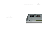
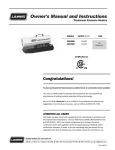
3.1 How to Connect All Parts
The connection layout for the SVR 430, the monitor, CCTV and external devices are described below.
!
"
19
3.2 Detailed Connection
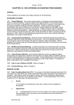
3.2.1
How to Install Removable HDD Rack
1. Disconnect the power of the unit for installation of the removable HDD.
2. Be sure to set the removable HDD to the Slave Mode by adjusting the jumper setting (The HDD
may be damaged if it is set to the Master Mode).See the instruction on the HDD to adjust the jumper
setting of the HDD.
3. For inserting the removable HDD on the HDD rack, push the removable HDD until you hear the
’Click’ sound.
4. After inserting the removable HDD, put the key into the hole on the front of the HDD rack and turn
the key in a counterclockwise direction to secure the HDD rack. Next, turn the power of the unit on.
5. After the power is on, check whether the Green LED on the removable HDD is lit. If the Green LED
is OFF, repeat from Step 1 to 3.
Caution
3.2.2
Be sure to turn the power of the main unit off for inserting and removing the removable HDD.
Rack Mount
The rack mount shall be mounted before installation of the unit. The rack mount is mounted in accordance
with the procedure below.
1. Mount the rack mount on the unit.
2. Insert the unit on the 19" rack.
20
3.2.3
Power
1. Before power connection, select the voltage according to the requirement below. The factory default
value is 230V.
CAMERA
MONITOR OUTPUT
AUDIO
VGA
IN
VIDEO1
OUT
RS-232C
VIDEO2 S-VIDEO
Caution
• Do not insert 230V when the Power Changeover Switch is set at 115V. (For
operations at 230V, be sure that the Power Changeover Switch is set at 230V).
• Do not insert 115V when the Power Changeover Switch is set at 230V. (For
operations at 115V, be sure that the Power Changeover Switch is set at 115V).
2. Check the Power Changeover Switch and connect the power cable.
3.2.4
Camera
SVR 430 can accommodate up to 4 cameras for CCTV.
Connect the BNC terminal of each camera to the CAMERA IN terminal of the unit.
CAMERA
MONITOR OUTPUT VGA
VIDEO1
AUDIO
IN
OUT
RS-232C
VIDEO2 S-VIDEO
MONITOR OUTPUT VGA
AUDIO
RS-232C
Caution
• If the BNC terminal is connected only to the CAMERA IN terminal, the terminal resistance
of 75Ω is internally set.
• If the BNC terminal is connected both to the CAMERA IN and CAMERA OUT terminals,
terminal resistance in the receiving device must be set to 75Ω.
• The CAMERA OUT terminal is the loop output for the camera input. Thus, it needs to be
connected only when there is a video input in the CAMERA IN terminal.
• If the cable to the CAMERA OUT terminal remains idle without connection to other external devices, it can degrade image qualities.
• Video input standards (NTSC/PAL) are automatically identified when you press the
ON/STAND–BY button of the unit. However, if you connect the CCTV camera with different video input standard to the CAMERA IN terminal while using the unit, the video input
standard is recognized only when you restart the unit.
21
Note
Images from each camera are simultaneously displayed on the external devices connected to
the CAMERA OUT terminal on the rear of the unit.
3.2.5
Audio Connection
The Samsung SVR 430 can save audio information. For storage or output of audio information, it is
required to connect the relevant devices.
Audio Input
Connect the RCA Audio Input Terminal (camera with built-in microphone, etc.) to the AUDIO IN terminal
on the rear of the unit.
Note
• For audio input setting, set [Audio] to [ON] on the Recording Setting on the Setting
Menu.See Paragraph 4.6 - Recording Setting for details.
• If audio is saved during recording, you can listen to the audio contents during playback
regardless of the Split Screen Mode.
Audio Output
Connect the RCA Audio Output Terminal (monitor with a speaker, etc.) to the AUDIO OUT terminal on
the rear of the unit.
22
3.2.6
Monitor
Connect the VIDEO 1 terminal of the MONITOR OUTPUT and the BNC terminal of the monitor using the
BNC cable for video data output to the main monitor. Total Monitor Output Terminals are 4 (2 BNCs, 1
S-VIDEO and 1 VGA) and accommodate up to three auxiliary monitors.
3.2.7
External Connector
Alarm Input(ALARM IN)
This external sensor connection terminal transfers data from the connected sensor or device to the unit.
No.
1, 2, 3, 4
G, G, G, G
Description
External Alarm Input.
Common Ground
23
Relay Output (RELAY OUT)
This Alarm Output terminal uses the contact relay for the alarm output to the external devices.You can
select NO (Normal Open), CM (Common) or NC (Normal Close) for connection according to the contact
point status.
No.
Description
1
NO
2
3
4
NO
5
6
Note
Relay 1
No.
Description
7
NO
CM
8
CM
NC
9
NC
10
NO
CM
11
CM
NC
12
NC
Relay 2
Relay 3
Relay 4
The operation of each relay output can be defined by a combination of Video Loss, Motion
Detect, Sensor, and Power in the Event Setting on the Main Menu. See Paragraph 4.7.4 Relay Setting for details.
24
External Control Device Terminal(RS–422/485)
This terminal is connected to external control devices.The switch marked as TERM turns on and off the
termination resistance of RS–422/485 communication device.
No.
Classification
Description
RS–422
RS–485
1
TX+ (+Transmit Data)
Data+
2
TX– (–Transmit Data)
Data–
3
GND (Ground)
GND (Ground)
4
RX+ (+Receive Data)
Data+
5
RX– (–Receive Data)
Data–
6
GND (Ground)
GND (Ground)
Caution
When using RS–485, connect TX+ and RX+ to Data+ and connect TX– and RX– to Data–.
25
LAN Connection(Ethernet 10 Base–T)
This port is to connect to a network.
CAMERA
AUDIO
MONITOR OUTPUT VGA
VIDEO1
IN
OUT
RS-232C
VIDEO2 S-VIDEO
No.
Description
No.
Description
1
TX+ (Transmit Data)
5
N/C (No connection)
2
TX– (Transmit Data)
6
RX– (Receive Data)
3
RX+ (Transmit Data)
7
N/C (No connection)
4
N/C (No connection)
8
N/C (No connection)
Monitor Output(VGA)
This is the output connector for VGA Monitor.
No.
Description
No.
Description
1
Red Signa(75Ω, 0.7Vp–p)
9
N/C(No connection)
2
Green Signal(75Ω, 0.7Vp–p)
10
Ground
3
Blue Signal(75Ω, 0.7Vp–p)
11
Ground
4
N/C(No connection)
12
N/C(No connection)
5
Ground
13
HSYNC (Horizontal Synchronization)
6
Ground
14
VSYNC(Vertical Synchronization)
7
Ground
15
N/C(No connection)
8
Ground
Caution
26
For the regions using PAL, Some TFT LCD monitors are not supported.
Communication Port(RS–232C)
This port is connected to control the unit through the connection with a PC.
CAMERA
MONITOR OUTPUT
VGA
AUDIO
IN
VIDEO1
RS-232C
OUT
VIDEO2 S-VIDEO
No.
Description
No.
Description
1
N/C(No connection)
6
N/C(No connection)
2
RxD(Receive Data)
7
N/C(No connection)
3
TxD(Transmit Data)
8
N/C(No connection)
4
N/C(No connection)
9
N/C(No connection)
5
GND(Ground)
27
Chapter 4
How to Set
4.1 Menu Configuration
¤
¡
Press a function button on the front side of the unit or the £MENU ¢button on the remote control, and the
menu for a variety of settings related to the unit will appear.The menu is configured as described below.
Note
The factory default language is Korean. See Paragraph 4.10.4 - Other Settings for language
setup.
28
The menu is configured as illustrated below. See Paragraph 4.2∼ 4.10 for more details.
tGtG
zG
zGzG
G
G
GGGGG
G
G
G
GGGGG
G
G
G
G
G
G
G
yGzG
G
G
GGGGG
G
G
G
GGGGG
G
G
G
GGGGG
G
G
G
G
G
GGGGG
G
G
G
G
G
lGzGGGGG
G
G
GGGGG
G
G
G
G
G
G
G
GGGGG
G
GG
G
G
GG
joX¥[
zlx|lujpunGG
GGGGjoX¥[SGxGk~lssG{ptlSG}pklvsvzzGzrpw
G
G
G
z{h{|zG GGG
G
G
G
G
GGGGjsvjrGkpzwshSGokkGmyllGzwhjlSGyljvykGz{h{|zSG
GGGG{p{slGkpzwsh
GG
GG
G
G
ylwlh{G GGG
GGGGh|{vGklsl{lGtvklSG~hyupunGsl}ls
j|yylu{G
GGGGyljvykGtvkl
G
thu|hsG G
GGGGpthnlGzplSGyljvykGx|hsp{SGyljvykGyh{lSGh|kpv
G
G
G
G
G
GGG
G
zjolk|slGG
GGGGpthnlGzplSGyljvykGx|hsp{SGyljvykGyh{lSGh|kpvSG
G
G
GGGGzjolk|sl
G
GGGGGGGGGGGGGGGGGGG
G
l}lu{G GGG
GGGGpthnlGzplSGyljvykGx|hsp{SGyljvykGyh{lSGh|kpvS
G
G
GGGGwvz{Gl}lu{Gk|yh{pvuSGwylGl}lu{Gk|yh{pvuG
joljrG GGG
GGGGjoljrGl}lu{SG{ptlGvulGzl{
G
tkG
GGGGjoX¥[Gtv{pvuGkl{lj{G
G
zluzvyG GG
GGGGzluzvyGX¥[G{wl
G
ylshG
GGGG{wlSGtkSGzluzvySG}TsvzzSGwSGylshXG¥G[G
G
G
G
G
kpzwshG GG
G
G
GGGGl}lu{GtlzzhnlSGi|lySGz~p{joG{vGl}lu{GzjylluSG
GGGGl}lu{GkpzwshGtpuG{ptlSGl}lu{GkpzwshGthG{ptl
G
G
joX¥[GG G
GGGGw{GjhtlyhGpkSGtvkls
G
G
ul{~vyrG
GGGG{wlSGkzsGpkVw~SGkojwSGpwGhkkylzzSGz|iul{GthzrSGGGG
G
GGGGGGGGGGGGGGGGGGnh{l~hSGkuzSGwvy{SGz~y
G
yzTYZYGG G
GGGGih|kGyh{lSGkh{hGip{SGwhyp{Gip{SGz{vwGip{
G
yzT[YYV[_\GG
GGGGzz{ltGpkSGih|kGyh{lSGkh{hGip{SGwhyp{Gip{SGz{vwGip{
G
G
G
G
G
G
z GzG
G
GGGGG
G
G
G
G
G
G
G
GGGGG
G
G
G
G
G
G
G
lTthpsG G
GGGGlTthpsGzl{|wSGpkSGzt{wGzly}lySGh|{ovyph{pvu
G
okkGG
GGG
G
GGGGyTokkGtvklSGmplkGokkGmvyth{SGihjr|wGokkGmvyth{GG G
G
G
G
whzz~vykzGGG
GGGG|zlyGwhzz~vykSGhktpuGwhzz~vykSGjoljrGh{Gzl{|wSGG
G
GGGGGGGGGGGGGGGGGGjoljrGh{Gwv~lyTvuSGjoljrGh{Gwv~lyTvmmSG
G
G
GGGGjoljrGh{GyljvykTvmmSGyltv{lGzl{|wSGyltv{lGylsh
G
G
kh{lGzl{|wG
G
G
GGGG{ptlGzl{|wSGkh{lGmvyth{SGtvu{oGmvyth{S
GGGGkhspno{Gzh}punzSGkszGz{hy{SGkszGlukG
GGGGG
G
G
G
l{jGG
G
GGGGshun|hnlSGh|kpvGpuw|{G{wlSGyltv{lGpkSGrlGi|lySG
GGGGmpyt~hylGkv~usvhkSGklmh|s{
G
G
G
G
w{GzG
G
G
GG
jG
G
G
G
G
GGGGG
G
G
G
GGGGG
G
G
G
GGG
zGz
G
G
G
G
G
G
GGGG{p{slSGiypno{ulzzSGjvu{yhz{SGzohywulzzSGjv}ly{
G
GG
29
4.2 Default Setup
The SVR 430 is delivered to customers with the factory default values as described below. To initialize
the menu setup to the factory default values, select [YES] for the [DEFAULT] item in [SYSTEM SETUP]–
[ETC] on the menu. Then, all setting values changed by users are initialized to the default values as
illustrated below.
■ Screen Setup
Main Menu
CH1 ∼ 4
SEQUENCING
STATUS
Submenu
DEFAULT
TITLE
1, 2, 3, 4
BRIGHTNESS
0
CONTRAST
0
SHARPNESS
1
COVERT
OFF
CH1 ∼ 4
3sec
Quad DWELL TIME
3sec
VIDEOLOSS SKIP
OFF
CLOCK DISPLAY
ON
HDD FREE SPACE
ON
RECORD STATUS
ON
TITLES DISPLAY
ON
■ Record Setup
Main Menu
REPEAT
Submenu
DEFAULT
AUTO DELETE MODE
ON
WARNING LEVEL
5%
CURRENT
RECORD MODE
MANUAL
MANUAL
IMAGE SIZE
640×240
RECORD QUALITY
MID
RECORD RATE
3333
AUDIO
OFF
IMAGE SIZE
640×240
RECORD QUALITY
MID
RECORD RATE
3333
AUDIO
OFF
SCHEDULE
-
IMAGE SIZE
640×240
RECORD QUALITY
MID
RECORD RATE
3333
AUDIO
OFF
POST EVENT DURATION
10sec
PRE EVENT DURATION
1sec
SCHEDULE
EVENT
30
■ Event Setup
Main Menu
CHECK
Submenu
CHECK EVENT
DEFAULT
OFF
TIME ZONE SET
MD
CH1 ∼ 4 MOTION DETECT
ON
SENSOR
SENSOR1 ∼ 4 TYPE
NO
RELAY
-
-
DISPLAY
EVENT MESSAGE
ON
BUZZER
OFF
SWITCH TO EVENT SCREEN
OFF
EVENT DISPLAY MIN TIME
3sec
EVENT DISPLAY MAX TIME
5sec
■ PTZ Setup
Main Menu
CH1 ∼ 4
Submenu
DEFAULT
PTZ CAMERA ID
0
MODEL
NONE
■ Communication
Main Menu
NETWORK
RS232
RS422/485
Submenu
DEFAULT
TYPE
Ethernet
xSDL ID, PW
svr430, svr430
DHCP
OFF
IP ADDRESS
000.000.000.000
SUBNET MASK
000.000.000.000
GATEWAY
000.000.000.000
DNS
000.000.000.000
PORT
3495
BAUD RATE
9600
DATA BIT
8
PARITY BIT
NONE
STOP BIT
1
SYSTEM ID
1
BAUD RATE
9600
DATA BIT
8
PARITY BIT
NONE
STOP BIT
1
31
■ System Setup
Main Menu
HDD
Submenu
DEFAULT
FIXED-HDD FORMAT
BACKUP-HDD FORMAT
R-HDD MODE
PASSWORDS
BACKUP
USER PASSWORD
ADMIN PASSWORD
DATE SETUP
CHECK AT SETUP
OFF
CHECK AT POWER-ON
OFF
CHECK AT POWER-OFF
OFF
CHECK AT RECORD-OFF
OFF
REMOTE SETUP
ENABLE
TIME SETUP
DATE FORMAT
DD/MM/YY
MONTH FORMAT
TYPE1
DAYLIGHT SAVINGS
OFF
DST START
April/04/First/Sunday
2004/04/04 02:00>03:00
DST END
Oct./24/Last/Sunday
2004/10/24 02:00>01:00
ETC
LANGUAGE
Korean
AUDIO INPUT TYPE
LINE
REMOTE ID
ALL
KEY BUZZER
ON
FIRMWARE DOWNLOAD
DEFAULT
32
4.3 How to Use Jog/Shuttle
• How to Change and Select Menus using Jog/Shuttle
– Turn the Shuttle Ring clockwise to move the cursor to the right. When the cursor reaches the
right end of a line, it moves downward to the next line.(To move the cursor to the next line, turn
the Shuttle Ring clockwise to end.)
– Turn the Shuttle Ring counterclockwise to move the cursor to the left. When the cursor reaches
the left end of a line, it goes to the left of the next line. (To move the cursor to the left of the
next line, turn the Shuttle Ring counterclockwise to end.)
– When the cursor reaches the desired position, set the values on the menu using the Jog Dial.
• How to Change and Select Menus using the Arrow Button
– J I: Moves the cursor to the left or right.
– N H: Moves the cursor up or down.
–
Note
: Increases or decreases setting values.
See Paragraph 2.3.1 - Front Control Panel for names and functions of the Jog/Shuttle Ring.
33
4.4 Menu Screen Setup
¤
¡
Select the £MENU ¢button on the remote control or the main unit, and the following Menu Screen appears.
¤
Note
¡
Press the £MENU ¢button, and the background screen is switched to the Split 4 screen.
• Main Menu: Select the Main Menu corresponding to each Tab.
• Submenu: Select the Submenu that can be set up on the Main Menu.
• Setup Items: Change the settings on the Submenu.
• How to Set: This message provides the guide for menu setup.
• It may take a little while for the recording setup. Then, please wait for a while.
• Except for the recording setup, setting changes are immediately applied.
Operations
• Operate the unit using the buttons on the main unit.
– Move between Menus to Left/Right: Press the Arrow J I buttons.
¤
¡
– Select Menu: Press the £ENTER ¢button.
– Change Setting Values: Turn the Jog Dial or press the
buttons.
¤ ¡
– Exit from Menu Screen: Press the £ESC ¢button.
• Operation using the Remote Control
– Move between Menus to Left/Right : Press the Arrow J I buttons.
¤
¡
– Select Menu: Press the £ENTER ¢button.
– Change Setting Values: Press the (–) (+) buttons.
¤ ¡
– Exit from Menu Screen: Press the £ESC ¢button.
34
4.5 Screen Setup
¤
¡
Press the £MENU ¢button and select the
Tab using the Left(J)/Right(I) arrow button, and the submenu
¤
¡
related to the live monitoring screen appears as illustrated below. Press £ENTER ¢and select the submenu
¤
¡
using the Left(J)/Right(I) arrow button. Next, press £ENTER ¢again, and you can select setup items by
pressing the Up(N)/Down(H) button.
4.5.1
CH1 ∼ CH4
Selects setup items related to channels such as channel titles or brightness.
35
• Channel Titles: Titles can be individually set to each channel. Select the channel title and press
¤
¡
£ENTER ¢. Then, the keyboard to enter the title is displayed as illustrated below.
The positions of characters in the Channel Titles can be arranged using the Jog
Dial.
¡
¤
– After the cursor is moved, press the £ENTER ¢button to select the relevant character.
¤ ¡
– To exit from the Menu Setup, press the £ESC ¢button.
– Press the Up/Down arrow buttons to move between character strings.
¤
¡
¤
¡
– To insert spaces, move the cursor to £SPACE ¢ on the screen and then press £Enter ¢ on the
remote control or the main unit.
• BRIGHTNESS: Adjusts the screen brightness by changing the values.
• CONTRAST: Adjusts the screen contrast by changing the values.
• SHARPNESS: Adjusts the screen sharpness by changing the values.
• COVERT: Doesn’t display the video on the live screen while video recording and playback are
enabled.
36
4.5.2
SEQUENCING
The live screens are automatically switched in the order of <CH1 → CH2 → CH3 → CH4 → Quad Dwell
Time> at the predefined switching interval. The channel switching interval can be set from 1 up to 99
on the [SEQUENCING] menu. Any channels that are set to [OFF] are not displayed in the Auto Screen
Display Switching Mode.
• CH1 ∼ 4: Sets the screen display duration by channel.
• Quad DWELL TIME: Sets the duration of the Spilt 4 screen for four channels.
• VIDEOLOSS SKIP [OFF/ON]: With Videoloss Skip [ON], channels without video input signals are
automatically skipped and only channels with video input are displayed.
4.5.3
STATUS
Selects information to display on the live screens.
37
• CLOCK DISPLAY [ON/OFF]: With Clock Display [ON], the current time is displayed on the live screens.
• HDD FREE SPACE [ON/OFF]: With HDD Free Space [ON], the free space on the HDD for recording
is indicated.
• RECORD STATUS [ON/OFF]: With Record Status [ON], the recording status ([NNNN]) is displayed
on the upper right corner of the screen during recording.
See Paragraph 5.4 - Recording for more details about Recording Status Display.
Note
• TITLES DISPLAY [ON/OFF]: With Titles Display [ON], the titles of [CH1 ∼ 4] set on the Channel Title
submenu by uses are displayed on the live screens.
4.6 Record Setup
¤
¡
Press the £MENU ¢button and select the
Tab using the Left(J)/Right(I) button. Then, the submenu
¡
¤
related to recording appears as illustrated below. Press £ENTER ¢ and select the submenu using the
¤
¡
Left(J)/Right(I) button. Next, press £ENTER ¢again, and you can select setup items using the Up(N)/Down(H)
button.
38
4.6.1
REPEAT
Monitoring screens can be recorded on the HDD and the storage capacities vary on HDD types mounted
on the unit.
• AUTO DELETE MODE [ON/OFF]: Sets whether to repeat recording.
– ON: If no storage spaces are left on the HDD, recording is continued by overwriting the oldest
data.
– OFF: If no storage spaces are left on the HDD, recording is stopped.
• WARNING LEVEL: When the remaining capacity of the HDD reaches the predefined percentage,
a warning message is displayed to users.The warning level can be set from 1 to
10%, 5 ∼ 10% in general.
39
4.6.2
CURRENT
Select one of three methods below to record monitoring screens.
• MANUAL: Immediate manual recording.
• SCHEDULE: Reserved recording.
• EVENT: Recording is triggered when a security device is opened or abnormal operation is
detected. Events to trigger recording are described below.
– Motion Detection: Any changes on a screen from a camera are treated as events.
– Alarm by Sensor: Data from devices connected to ALARM IN terminals on the rear of the unit
such as sensors are treated as events.
– Videoloss: The cameras without video signals are treated as events.
40