1
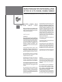
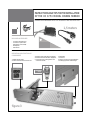
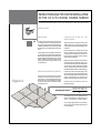
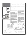
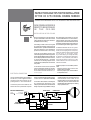
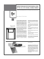
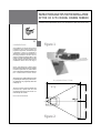
INSTRUCTIONS AND TIPS FOR THE INSTALLATION
OF THE HC 37.53 MODEL CINEMA MIRROR
GENERAL RECOMMENDATIONS FOR ASSEMBLY AND INSTALLATION
1
CONSIDERATIONS
figure 1
Cinema Mirror is an active optic set to be
installed in false ceilings hiding the
projection equipment, and that through
a pulsation it opens a floodgate of
335x335 mm., allowing the projection of
the image, thanks to its two mirrors,
without causing the trapeze effect on the
image. For that, Cinema Mirror and the
screen must be in the same plane or with
a difference from 0 to 12 cm. (Fig. 1).
Some manufacturers of Data -Video
projectors include electronics for a trapeze
correction higher than 27º, which allows
us to increase the level difference between
the Cinema Mirror and the screen.
Always be sure to perpendicularly set the
projected light with the projection screen,
any difference may negatively affect the
image (Fig. 2).
The optic mirrors of this equipment are
pro tected by a plastic film to avoid
accidents. Remove this film when it is
indicated by this manual.
d = projector’s focal – 20 cm.
x=y
y
Do not do so beforehand.
x
figure 2
INSTRUCTIONS AND TIPS FOR THE INSTALLATION
OF THE HC 37.53 MODEL CINEMA MIRROR
GENERAL RECOMMENDATIONS FOR ASSEMBLY AND INSTALLATION
2
BEFORE USING FOR
THE FIRST TIME
Before proceeding to the installation and
manipulation, read carefully this manual and
follow conscientiously all the warnings and
cautions that are described.
SAFETY RULES
WARNING
The equipment should be installed by
installers specialized in public locations. Install
and protect the line in accordance with the
low-tension electrical technical regulations,
as well as the MIE-BET-025 complementary
technical instructions, “Installations in
locations of public concurrence”. The
equipment should be connected to ground
protection.
All the required electric works of this
equipment should be carried out by
electricians, qualified electronics or
competent people according to the electrical
technical regulations of each country.
The equipment should be secured to the
bracket or the ceiling using screws that must
be able to withstand the weight of the
equipment, with the screw having a
minimum diameter of 10 Metric mm. If the
equipment is adjustable, mobile, above the
audience or excessive in weight, for safety
reasons it should be secured with a chain
(4 mm link thickness) or cable (of 6 mm
diameter steel), from the equipment to the
building structure, be it the ceiling, floor or
walls that support at least 10 times the
weight of the equipment.
The equipment operation is: for interior use
in a ventilated space.
The operating position is horizontal with the
hatch facing downward.
The equipment will not be accessible during
operation, before accessing the means of
connection or the inside of the equipment,
all electrical alimentation circuits of the
equipment must be disconnected.
In the event of any questions, contact the
Technical Service or your distributor.
The alimentation requires an automatic
bipolar switch with MIN IMUM 3 mm
separation between contacts.
Flammable materials must not be
placed within a radius of 1 meter
o f the equipment (see instruction
manual of video projector to be installed).
Secure and protect the alimentation cables
and hoses, gear, material, etc. in such a way
that they are not near: moving parts or heat
sources.
The equipment must be installed in the
ceiling at a distance so that it is not within
arms reach of a person. Secured above the
site itself or on a metallic bracket strong
enough to hold the weight of the equipment
plus the image projector.
SAFETY
The equipment should be examined every
90 days, the structure fasteners, movable
parts, mechanical cables, electrical parts, etc.
should be checked and lubricated if
necessary.
Do not install this unit in an unstable place.
Do not alter neither modify this unit.
Do not use this unit in a bathroom neither
near liquids or inflammable gases.
Do not connect the unit to an electric tension
different from the one specified.
Do not force the storm door in their opening
or closing journey, since the mechanics of
the motor could be seriously damaged.
INSTRUCTIONS AND TIPS FOR THE INSTALLATION
OF THE HC 37.53 MODEL CINEMA MIRROR
GENERAL RECOMMENDATIONS FOR ASSEMBLY AND INSTALLATION
1,5 meters
3
INCLUDED ACCESSORIES
- Connection Cable 230 V.A.C.
- Connector for push-button
(Push-button not included)
- Graded plate
- User Manual
DEFINITION AND FUNCTION OF
COMPONENTS
3 Protection case of the electric equipment
4 Protection case of the mechanic equipment
5 Connection of the pushing-button and
connection 230 VAC
1 Variable position table
2 Position control lever of the active lens
6 Passive lens
7 Active lens
8 Closing connecting rod and parallelism
9 Leveling supports of variable height
ADJUSTING
SCREW
(6)
(8)
(5)
(3)
(4)
(2)
(7)
(1)
(9)
(9)
figure 3
INSTRUCTIONS AND TIPS FOR THE INSTALLATION
OF THE HC 37.53 MODEL CINEMA MIRROR
GENERAL RECOMMENDATIONS FOR ASSEMBLY AND INSTALLATION
INSTALLATION
CHOOSE THE PLACE OF THE
INSTALLATION
PROCEDURE
4
Cinema Mirror has been built with the
knowledge of technical ceiling features. For
this reason, it has leveling supports (see Fig.
3 Detail 9) that adapt to the “T”ceiling profiles
and allow you to install it without the use of
tools.
If the ceiling is made of plaster, wood, glass,
etc. and it does not have profiles, adapt a HC
60.60 model ceiling frame kit. An aluminium
profile designed to adapt ceilings to Cinema
Mirror and give access to the interior of the
ceiling (see accessory page). Order it from
your distributor.
BEFORE PROCEEDING TO INSTALL
figure 4
The area where Cinema Mirror will be
installed, next to the projection equipment,
will support an extra weight. Reinforce the
perimeter next to the installation area (Fig.
4) with the accessories recommended by
the manufacturer.
The projectors do not have the same focus
distance. If you do not know the optic data
of the projector ready to be installed proceed
as follows.
Place the projector on a table. Connect the
electric current to the projector and switch
on the projection equipment. Leave it for a
few minutes so that the projector reaches
its maximum brightness.
Keeping the zoom control in the maximum
opening, bring the equipment closer to, or
move it further away from the test wall that
you have chosen until obtaining the desired
screen - image width. In this case, measure
the distance between the lens and the image.
Put the zoom in the minimum opening, and
move the projector away until obtaining the
same screen width than the obtained in the
previous paragraph, and measure the
distance between the lens and the image.
Calculate the focal distance with the
following formula:
Average optic center =
maximum zoom distance (cm)
+ minimum zoom distance (cm)
2
The average optic centre determines the
distance and the place to install the projector
and in consequence Cinema Mirror.
You can get bigger precision if you deduct
20 cm of the journey from the projector lens
to the active lens.
INSTRUCTIONS AND TIPS FOR THE INSTALLATION
OF THE HC 37.53 MODEL CINEMA MIRROR
GENERAL RECOMMENDATIONS FOR ASSEMBLY AND INSTALLATION
INSTALLATION
5
right
centred
left
UNPACKAGING AND PROCESS OF
ASEMBLY
Open the box of the Cinema Mirror and take
out the protection butt plates.
Take out the plastic covers.
Take out the rubber of protection of the
floodgate of the active mirror.
Place a fabric table cloth on a board, table,
bench, etc. to protect and take care of the
paintwork on the equipment gate. Separate
the bevel from the gate and leave it ready
to be installed later in the ceiling finish. Leave
Cinema Mirro r o n the table cloth.
Projectors do not always have the optic
in the same place; it can be to the left,
centred, or to the right.
For this reason, Cinema Mirror is equipped
with a tray called variable position table
(Fig. 5).
The variable position table has 5 positions:
1 centred, 2 moved to the left, 3 moved to
the right, 4 turned 180º and centred, and 5
turned180º and to the right.
Remove the 6 screws that secure the table
to the Cinema Mirror chassis.
Secure the variable position table, with its
screws, in the best place so that the projector
rests on its support feet.
Place the projector on the variable position
table horizontally centred relative to the
passive mirror. This will be its working place.
ADJUSTMENT OF THE PASSIVE
MIRROR
To centre in height the passive mirror, (Fig. 3
detail 6), in relation to the lens of the projector,
remove the screws that hold it to the chassis
and move them up and down so that the
centre of the mirror stays at the centre of the
lens of the projector. Tighten firmly, but not
to strong, the axis of the mirror to the holes
of the chassis, to make possible an ulterior
adjustment of the axis.
Place the graded plate supplied with the
equipment on the Cinema Mirror profile
(Fig. 6).
figure 6
figure 5
The passive mirror should be placed to 37º
in relation to the base of the projector. Please
turn the passive mirror up so that the angles
between the mirror and the template
coincide in parallel. Fasten strongly the screws
of the axis of the passive mirror.
INSTRUCTIONS AND TIPS FOR THE INSTALLATION
OF THE HC 37.53 MODEL CINEMA MIRROR
GENERAL RECOMMENDATIONS FOR ASSEMBLY AND INSTALLATION
NOW CINEMA MIRROR IS
READY TO BE INSTALLED
IN THE CEILING
INSTALLATION IN THE CEILING
6
ELECTRICAL CONNECTION
Connect a pushing-button (not included, of
1A 230 V.A.C.) to the supplied entrance
connector. Insert the connector of the
pushing-button in the Cinema Mirror.
Connect the power source cable to the
electric net and to protect with a bipolar
ELECTRIC CURRENT INPUT
PHASE
EARTH ( )
NEUTER (N)
Remove the plate that coincides with the
projector focal distance from the technical
ceiling and leave it aside for its use later on
the final finish of the ceiling.
Now the height of the chassis can vary and
can be levelled with the roof. To level them,
please unfasten the screws of the leveling
supports which holds the chassis and screed
the latter to the same height of the surface of
If the ceiling is made of stucco, wood, glass the roof. Fasten again and strongly the screws.
etc, install the HC60.60 ceiling frame kit
beforehand; Four “T”profiles to be assembled ATTENTION PLEASE! The motor system
with its accessories so as to facilitate the (active door) is not prepared to carry heavy
perfect decorative finish of the ceiling. loads, as for example, parts in wood, cork,
glass, etc., that one might want to install
Insert the Cinema Mirror with the optic on the door as decoration items.
mirrors facing the place where the projection If you desire this, try to modify the finish,
screen will be installed. Place the chassis onto by painting or imitating the painting by
the “T” shaped profiles of the technical roof, means of a very thin foil, to be able to
(or the HC 60.60 frame Kit ), and make integrate the finish of the door of the
coincide the 2+2 leveling supports of the Cinema Mirror to the roof decoration in
chassis (Figure 3, detail 9) with the technical which it is installed.
roof profile.
Install the projector on the variable position
IF THE INSTALLATION IS NOT EQUIPPED table.
WITH A WORKABLE TECHNICAL CEILING, · Place the projector optic as close to the
BUILD YOUR OWN SPACE USING THE HC
passive mirror as possible.
60.60 MODEL CEILING FRAME KIT. (see · Place the projector optic centred relative
accessory page)
to the passive mirror.
switch (not supplied) with separation among
contacts of 3 mm. (ELECTRIC DIAGRAM)
Connect the video, DVD, PC, control signals,
etc, following the instructions of the
videoprojector maker. Secure the cables with
flanges or plastic loops, (available in shops),
CLOSING SWITCH
checking that they do not restrict the access
and movement of the chassis on the
technical ceiling “Ts” or supports. Move the
cables away from the area to facilitate the
later handling of the videoprojector: cleaning,
lamp replacement, etc.
OPENING SWITCH
(L1) BROWN
YELLOW / GREEN
BLUE
MOTOR
OPENING – CLOSING
BUTTON CONNECTION
IMPULS RELAY
INSTRUCTIONS AND TIPS FOR THE INSTALLATION
OF THE HC 37.53 MODEL CINEMA MIRROR
GENERAL RECOMMENDATIONS FOR ASSEMBLY AND INSTALLATION
HOW TO ADJUST THE
IMAGE TO THE SCREEN
ATTENTION – DANGER !!
7
figure 7A
Take out he rubber that blocks the door
during the transport (if you have not already
made it), before triggering the movement
pushbutton of the active mirror gate, make
sure that there are no obstacles hindering
its opening or closing. Do not make any effort
to stop or help the active mirror gate in its
path, the mechanics of the motor can be
seriously damaged and the warranty of the
product will be lost.
· Place the control lever on the upper part.
· Activate the motor with the installed pushbutton.
· Observe the image that is projected on the
screen. To lower the image the control lever
should be moved downward. The motor
actives and positions the active door as
desired.
· Repeat this operation until reaching the
desired image height.
If you observe any defect, this may be due
to the handling or lack of care during
transport of Cinema Mirror. Contact your
distributor's technical service.
ATTENTION.
Activate the button for opening or closing
(not included) on the Cinema Mirror. The
motor of the active mirror will be put into
operation.
Remove the film that protects the optic
mirrors during transport and pre-installation.
Switch on the projector and wait a few
minutes so that the projector reaches its
maximum brightness.
The light or image thrown by the projector
through the active mirror determines the
place where the projection screen should
be installed.
Remember that you can work on the
projector zoom to fix the screen width.
Install the projection screen guided by the
light spectrum thrown by the projector. If
you use a screen with black side margins,
the image will be better profiled; as television
sets do in their cathode ray tubes.
figure 7B
INSERT A VIDEO OR PC SIGNAL IN
THE INS TA LLED PROJECTOR
The control lever of red color regulates the
position and opening of the active mirror
(Fig. 3 detail 2) and consequently, the
projection height on the screen.
If the whole image is not represented on the
projection screen, this may be due to the fact
that:
• The projector zoom is closed.
• The projector is very near the passive mirror.
• The active mirror is excessively closed.
Correct these differences.
The image may not be parallel with the
projection screen base due to height
differences between the place of installation
of the screen and that of the projector (Fig. 7A).
In the connecting rods that move the active
mirror, (Fig 3 detail 8) there is a connecting
rod-active mirror regulation screw that
corrects the defect. If you want to lift the image,
move the connecting rod screw of the place
affected upwards. (Fig. 7B)
Remember the adjustment elements that you
have to obtain a cinema image.
1. - Projector zoom and focus.
2. - Vertically adjustable feet, in the projector.
3. - Trapeze correction, manual, automatic or
electronic, in the projector.
4. - Passive mirror turn.
5. - Active mirror movement
6. - Horizontal image control in the connecting
rods.
7. - Left / right movement of the projection
screen (only some makers)
8. - Regulation of the height extension of the
projection screen.
INSTRUCTIONS AND TIPS FOR THE INSTALLATION
OF THE HC 37.53 MODEL CINEMA MIRROR
GENERAL RECOMMENDATIONS FOR ASSEMBLY AND INSTALLATION
FINAL FINISH OF THE CEILING
8
figure 8
A
B
Once we are definitively satisfied with the
image obtained, we will proceed to close the
ceiling with the same material used by the
maker of the technical ceiling. If you use other
materials, try to use materials with a very low
weight. Consult the possibilities of painting
or masking of the material used for a correct
simulation with the original ceiling.
ATTENTION PLEASE! The motor system
(active door) is not prepared to carry heavy
loads, as for example, parts in wood, cork,
glass, etc., that one might want to install on
the door as decoration items.
If you desire this, try to modify the finish, by
painting or imitating the painting by means
of a very thin foil, to be able to integrate the
finish of the door of the Cinema Mirror to
the roof decoration in which it is installed.
Take the measurements in which the gate
was located with the frame, measurements
A and B (Fig 8). Mark the measurements A
and B on the technical ceiling plate
(60x60cm), (or replacement material).
Place the bevel on the marks A and B, and
draw the contour lines. With a cutting tool
remove the space that must be occupied by
the gate.
The installer should locate his working
position in the square of the technical ceiling
plate, adjacent to the Cinema Mirror
installation.
Move the Cinema Mirror-projector set as
much as is necessary to install the modified
technical plate.
Place the Cinema Mirror-projector set in the
space chosen.
Lightly press the bevel pins outwards and
adjust them to the gate.
Check the light-image on the screen.
Provide the finishing touches to the ceiling
finish according to the characteristic
requirements of the space.
MAINTENANCE
The mechanics and mobile parts of the
equipment don't specify of a severe
maintenance, but if it is convenient the
application of a lubricant in the mobile parts,
with a minimum periodicity of 90 days.
Revise the electric installation and its
connections, likewise revise the anchorage
from the unit to the roof.
The optic lenses will clean with non abrasive
cloths, using neuter soaps or simply with
common water.
INSTRUCTIONS AND TIPS FOR THE INSTALLATION
OF THE HC 37.53 MODEL CINEMA MIRROR
GENERAL RECOMMENDATIONS FOR ASSEMBLY AND INSTALLATION
TECHNICAL SPECIFIC ATIONS
(dimen sion s in m m).
max 43
min 24
max 217 / min 170
9
395
max 265
610
ACTIVE
MIRROR
DOOR
TECHNICAL FEATURES
Supply:
Power:
Starter (push-button not included):
Noise level:
False ceiling minimum height:
Maximum height of floodgate slope:
Mirror opening time:
Motor reducer:
Minimum dimension of the hole to embed:
Mechanical Dimensions (mm):
Packed Dimensions (mm):
Net weight:
Gross weight:
395
230 V.A.C. 50 Hz
10 W
Instantaneous / 1 A to 230 V.A.C.
< 15 dB
From 170 mm to 217 mm
265 mm
30”
500/1
335 mm x 335 mm
LONG 625 / WIDE 395 / HIGH 170
LONG 680 / WIDE 460 / HIGH 240
8.2 Kg
12.3 Kg
OPT IO NA L
ACC E SS O R IE S
Frame Kit
Four aluminium sections, squares, screws,
etc.. to build a frame that replace the technical
ceiling outlines (Armstrong or similar), and
gives a professional ending and support in
plaster ceilngs, wood ceilings, etc… With a
professional ending as support on your
Cinema Mirror installations.
Inside Dimensions:
Outside Dimensions:
595x595 mm
645x645 mm
625