1
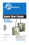
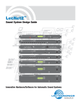
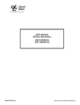
Quick
Start
Guide
Standard Belt-Pack
Transmitters
UM400a
UM450
LMa
U.S. Patent 7,225,135
Fill in for your records:
Serial Number:
This guide is intended to assist with
initial setup and operation of your
Lectrosonics product.
Purchase Date:
For a detailed user manual, download the most current
version at:
www.lectrosonics.com/manuals
06 jun10
Controls and Functions
UM400a, UM450
transmitters
LMa transmitter
Input Jack
Input Jack
Power LED
AUDIO LEVEL
Control
Power ON/OFF
Switch
Modulation
LEDs
AUDIO LEVEL
Control
Power LED
Modulation
LEDs
Power ON/OFF
Switch
Antenna Jack
Antenna
CIRCULATOR/ISOLATOR
1.6M
100K
Frequency Select
Switches
E
D
C
B
A
F 0 1
9 8 7
2
6
3
4
5
Sliding Door
E
D
C
B
A
F 0 1
9 8 7
2
6
3
4
5
1.6M
100K
Frequency Select
Switches
E
D
C
B
A
F 0 1
9 8 7
2
6
3
4
5
E
D
C
B
A
F 0 1
9 8 7
2
6
3
4
5
Low Frequency Roll Off
Control
2
LECTROSONICS, INC.
Audio Input Jack
Accommodates most lavaliere and dynamic microphones, and line level
signals.
Power ON/OFF Switch
Turns the transmitter on and off.
Power LED
Indicates power status and battery strength.
Audio Level Control
The front panel AUDIO LEVEL Control is used to adjust the incoming audio
input level for proper modulation.
Modulation LEDs
The two bicolor Modulation LEDs provide a visual indication of the input audio
signal level from the microphone.
Frequency Select Switches
Two 16-position rotary switches adjust the center frequency of the carrier. The
1.6M is a coarse adjustment and the 100K is the fine adjustment.
UM400a, UM450:
LMa:
Antenna
Antenna
The flexible galvanized steel cable
antenna supplied with the transmitter is removable via an SMA connector. Replacement antennas are
available.
Belt Clip
The belt clip may be removed for
special applications by removing
one hex screw, accessible through
the hole in the belt clip.
The flexible galvanized steel cable
antenna is permanently attached to
the transmitter
Belt Clip
The wire belt clip may be removed
for special applications by spreading
the wire away from the housing and
sliding it out of the holes.
WARNING: Use ONLY the screw
that is supplied.
Adjustable Low Frequency
Roll-Off
The 18dB per octave low frequency
roll-off control is used to remove
subsonic (or very low frequency)
audio, often produced by air conditioning systems, automobile traffic
and other sources.
www.lectrosonics.com
3
Operating Instructions
Selecting the Compatibility Mode
The UM400a, UM450, and LMa can be used with Lectrosonics 400 Series
Digital Hybrid, 200 Series analog, 100 Series analog and some non-Lectrosonics analog wireless receivers. Contact the factory for details on the
non-Lectrosonics models that can be used. The transmitter must be set to
the operating mode of the matching receiver, which is done using the supplied
screwdriver and a battery. The UM400a and UM450 are functionally identical, while the LMa lacks the manual low-frequency rolloff control. The LMa
has an output of 50mW, the UM400a has 100mW output, and the UM450 has
250mW output.
NOTE: The unit is supplied from the factory in the Hybrid mode.
1) Ensure the battery is good.
2) Turn off the transmitter.
3) With a small screwdriver (included), set the Frequency Select Switches to
CC. (for Change, Change).
4) Power up the unit briefly – just long enough for the LED’s to light up and
then turn it off - about one second.
5) Change the Frequency Select Switches to one of the following settings:
• To set Lectrosonics 100 Series mode:1,1
• To set Lectrosonics 200 Series mode:2,2
• To set Mode 3*:
3,3
• To set Lectrosonics Hybrid mode: 4,4
• To set IFB mode:
5,5
• To set Mode 6*:
6,6
* contact the factory for details
6) Turn the unit on, wait about one second and turn off again.
7) Change the Frequency Select Switches to 0,0.
8) Turn on the transmitter to complete the operation.
The LEDS will blink to indicate the selected compatibility mode. Immediately after power up, all LEDS will blink together red, then green,
followed by the audio level LEDs (-20 and -10) blinking to indicate the
mode.
The -20 and -10 LEDs will blink:
• Once for 100 Series mode
• Two times for 200 Series mode
• Three times for Mode 3
• Four times for 400 mode
• Five times for IFB mode
• Six times for Mode 6
At powerup the transmitter will confirm the current compatibility mode
with the number of blinks listed here. This setting will remain the same
until you reset it with the procedure listed above.
4
LECTROSONICS, INC.
Attaching a Microphone and Adjusting Gain
1) Ensure the battery is in good condition.
2) Insert the microphone plug into the input jack, aligning the pins; be sure
that the connector locks.
3) Attach the antenna to the SMA connector on the top of the transmitter.
4) Mute the associated receiver’s audio output.
5) Turn on the transmitter.
6) Position the microphone in the location you will use in actual operation.
While speaking or singing at the same voice level that will actually be
used, observe the Modulation LEDs. Adjust the AUDIO LEVEL control
until the –20 dB LED
Signal Level
-20 LED
-10 LED
glows green with occasional red flickers and
Off
Off
Less than -20 dB
-10 dB glows green.
Green
Off
-20 dB to -10 dB This will set the gain
Green Green of your transmitter so
-10 dB to +0 dB
peaks are between +0
Red
Green dB and +10 dB modula+0 dB to +10 dB
tion.
Red
Red
Greater than +10 dB
7) Once the gain has been adjusted, the mixer or recorder can be turned on
to make level adjustments.
NOTE: The transmitter Audio Level Control should not be used to
control the volume of your sound system or recorder levels. This gain
adjustment matches the transmitter gain with the user’s voice level and
microphone positioning.
Operating Notes
If the audio level is too high — both LEDs will blink red frequently or glow a
steady red. This condition may reduce the dynamic range of the audio signal.
If the audio level is too low — neither LED will glow, or only the -20 LED will
glow green. This condition may cause hiss and noise in the audio.
Different voices will usually require different settings of the AUDIO LEVEL
control, so check this adjustment as each new person uses the system. If
several different people will be using the transmitter and there is no time to
make the adjustment for each individual, adjust it for the loudest voice.
www.lectrosonics.com
5
Frequency Select Switches
Two 16-position rotary switches adjust the
center frequency of the carrier. The 1.6M
is a coarse adjustment and the 100K is the
fine adjustment.
Changing the Frequency
E
D
C
B
A
F 0 1
9 8 7
1.6M
2
6
3
4
5
E
D
C
B
A
F 0 1
9 8 7
2
6
3
4
5
100K
Locate the two small rotary switches. (On the UM400a/UM450, slide open
the small door on the side of the transmitter.) With the small screwdriver
supplied with the kit, turn the left
switch to the first character in the
two-digit Transmitter Frequency
Switch Setting code, then turn the
right switch to the second character
of the two-digit code. For example:
the frequency display
is 623.000,
F 0 1
F 0 1
2
2
E
E
Frequency
3
D and 3two-digit
D Transmitter
C
C
4
4
Switch
Setting
the
lefthand
switch
5 is 56, thus
5
B code
B
F 0 1
F 0 1
6
6
A
A
2
2
E
E
9 8 7
8 7
on your transmitter
should be9 set
to “5” and the
3
3
D
D
C
C
4
4
righthand switch to “6”.
5
5
B
B
A
9 8 7
6
A
9 8 7
6
5
6
Transmitter Frequency
Select Switches
Note: Be sure to orient the transmitter so the
nomenclature reads correctly (not upside down).
If you are using a receiver with a frequency scan function, find a clear frequency with the receiver, then set the transmitter to match. With Lectrosonics
400 Series receivers, a front panel LCD character display will indicate the
correct transmitter switch settings as a two-character alphanumeric hex code
once a clear frequency has been located with the scan function.
6
LECTROSONICS, INC.
Battery Installation
UM400a/UM450
To open the battery compartment,
press outward on the cover door in
the direction of the arrow as shown
in the illustration. Only firm, sliding
pressure is needed to open and
close the battery door. Swing the
door open and take note of the
polarity marked inside showing
the location of the positive (+) and
negative (-) terminals. You can also
see the large and small contact
holes inside the battery compartment with the door open.
Insert the battery correctly and
close the cover by pressing the door
closed and across, reversing the
opening procedure. If the battery is
inserted incorrectly, the door will not
close. Do not force the door closed.
LMa
To replace the battery, push up on
the Battery Compartment Door and
rotate it clockwise. Remove the old
battery and take note of the polarity
marked inside showing the location
of the positive (+) and negative (-)
terminals. (You can see the large
and small contact holes inside the
battery compartment with the door
open.)
Insert the new battery correctly
and close the Battery Compartment Door by reversing the opening
procedure. If the battery is inserted
incorrectly, the door will not fully
close. Do not force the door closed.
The Power LED glows green when the battery is good and the transmitter
is turned on. The LED will glow yellow/orange as the battery voltage drops
and finally glows red when there are about 30 minutes of operation left (when
using an alkaline battery). The LED then blinks red when there are only a few
minutes of life left.
NOTE: While a LiPolymer battery provides long operating time, it will
give little or no warning when depleted. If you use a LiPolymer battery
in the UM450, we recommend trying a fully charged battery in the unit,
noting the length of time that the battery will run the unit and in the
future use somewhat less than that time to determine when the battery
needs to be replaced.
A weak battery will sometimes light the Power LED to the “good” green indication immediately after being put in the unit, but will quickly discharge to the
point where the LED will go red or shut down (just like a flashlight with “dead”
batteries). If the lamp fails to light, the battery should be replaced.
www.lectrosonics.com
7