1
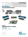
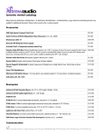
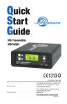
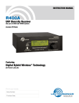
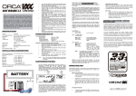
Quick Start Guide Digital Hybrid Wireless® Compact Receivers UCR411a UCR401 U.S. Patent 7,225,135 Fill in for your records: Serial Number: This guide is intended to assist with initial setup and operation of your Lectrosonics product. Purchase Date: For a detailed user manual, download the most current version at: www.lectrosonics.com/manuals 06 jun10 2 LECTROSONICS, INC. Menu Selections from Main Window Main Window Press All Buttons Frequency Scan Mode Press & Hold MENU SELECT Lock/Unlock Hold MENU & press UP U M P ress Pres ss Press UP Pre Setup Window EN Pilot Off/On M s U Frequency Window U Pre EN ss M M EN U EN Battery Level Window Level Press MENU Press MENU Press UP (Press UP / DOWN to adjust) Press MENU Audio Test Tone Audio Test Tone Press MENU Press UP Press UP (Press UP / DOWN to adjust) Tx Battery Type Press MENU Press UP Press MENU (Press UP / DOWN to select) Output Phase Press MENU Press UP Press MENU (Press UP / DOWN to select) Noise Reduction Press MENU Press UP Press MENU (Press UP / DOWN to select) Tuning Mode Press MENU Press UP Press MENU (Press UP / DOWN to select) Compatibility Mode Press MENU P re Press MENU (Press UP / DOWN to select) ss UP www.lectrosonics.com 3 Frequency Window (example) TV40 - The television broadcast channel the frequency falls within. AE - These are the correct settings for the frequency switches on your transmitter - see your transmitter instructions. 631.800 - Press the SEL Up and Down buttons to change the frequency of the receiver. Note: Be certain to change the transmitter frequency to match the settings shown in the Frequency window. When the TUNING mode is set to NORMAL, the SEL Up and Down buttons tune in single channel increments. In the GRP (group) tuning modes, the SEL Up and Down buttons move among the pre-selected set of frequencies. Note: See page 6 and the Instruction Manual for details on group tuning modes. Battery Level Window This window shows the transmitter (TX) and receiver (RX) battery voltage. These levels will flash when the voltages drop below optimum working levels. With dry cell batteries, 30 to 60 minutes of operating time will remain after the display begins to blink. Rechargeable batteries on the other hand will give little to no warning before the unit stops operating. RX changes to EX when the receiver is operating from an external power supply. Setup Window In the Setup window, the SEL Up and Down buttons scroll through the following eight possible setup screens: EXIT, LEVEL, TONE, TXBAT, PHASE, SmtNR (in 400 Series mode only), TUNING and COMPAT. 4 LECTROSONICS, INC. LEVEL The LEVEL setup screen displays the audio output level of the receiver in dBu. Use the SEL Up or Down buttons to change the level. Range is from -50 to +5 dBu in 1 dB steps. TONE The TONE setup screen enables an audio test tone at the receiver output for precise level matching with other equipment. The first screen prompts you to press the SEL Up button to enable the tone at the receiver output jack. The next screen that appears allows the level to be adjusted in 1dB steps using the SEL Up and Down buttons. TXBAT The TXBAT setup screen allows you to select the exact battery being used in the transmitter to provide more accurate battery level monitoring. Use the SEL Up and Down buttons to select the transmitter battery. Press MENU to leave this screen. In native 400 Series hybrid mode as well as in the 200 Series compatibility mode, the TXBAT menu offers six choices. (Monitor voltage with battery icon in main window unless otherwise noted): 9V ALK - 9V alkaline battery. 9V LTH - 9V lithium battery. 9V TIM - 9V battery. Display its voltage normally in the battery level window but monitor its status with the battery timer in the main window. AA ALK - AA alkaline battery. AA LTH - AA lithium battery. AA TIM - AA battery. Display its voltage normally in the battery level window but monitor its status with the battery timer in the main window. The 9V TIM and AA TIM settings are most useful for LiPolymer and NiMH rechargeable batteries as they do not exhibit reliably identifiable voltage drops as they discharge. In compatibility modes other than 400 Series and 200 Series, no battery telemetry information is available so the TXBAT setup screen offers only two choices: NOTIMER - Display no transmitter battery status in the main window. TIMER - Monitor the transmitter battery status with the battery timer in the main window. Note: To reset the battery timer, hold MENU and SEL Down together for one second. PHASE (Polarity) The output PHASE setup screen allows the audio output polarity to be inverted. The SEL Up and Down buttons can be used to toggle between normal and inverted polarity. Press MENU to leave this screen. www.lectrosonics.com 5 SmtNR SmtNR (smart noise reduction) applies a DSP algorithm to reduce high frequency noise in the audio. The algorithm is more than a roll-off filter, applying detection and reduction techniques only available in the digital domain. In the NORMAL mode a subtle process suppresses HF noise from sources such as FET noise in small lavaliere microphones. In the FULL mode more aggressive noise reduction will reduce even HF noise in the acoustic environment. TUNING The Tuning setup screen allows selection of one of four factory set frequency groups (Groups A through D), two user programmable frequency groups (Groups U and V) or the choice to not use groups at all. In the four factory set frequency groups, eight frequencies per group are preselected. These frequencies are chosen to be free of intermodulation products with each other. In the two user programmable frequency groups, up to 16 frequencies can be programmed per group. Note: The Tuning Setup Screen only selects the tuning mode (NORMAL or Group Tuning) and not the operating frequency. Actual operating frequencies are chosen through the Frequency Window. If NORMAL tuning mode is selected, the SEL Up and Down buttons select the operating frequency in single channel (100 kHz) increments and the MENU+Up and MENU+Down shortcuts tune in 16 channel (1.6 MHz) increments. The factory tuning groups provide intermod-free factory selected frequencies. The programmable tuning groups U and V allow you to build custom groups for particular purposes or coordination with other systems. Refer to the Instruction Manual for details on the factory selected tuning groups and for procedures for coordinating and checking out multi-channel systems. A lower case (a, b, c, d, u, v) will be displayed to the immediate left of the transmitter switch settings in the Frequency Window to indicate the selected tuning group. The indicator will blink when the receiver is set on a frequency that is not in the currently selected group. 6 LECTROSONICS, INC. Adding/Deleting User Programmable Frequency Group Entries Note: Each User Programmable Frequency Group (“u” or “v”) has separate contents. We recommend that you review the section titled Frequency Coordination in the instruction manual prior to adding frequencies in order to minimize potential intermodulation problems. 1.Start from the Frequency Window and verify that a lower case “u” or “v” is present next to the transmitter switch settings. 2.While pressing and holding the MENU button press either the SEL Up or Down button to move to one of the 256 available frequencies in the block. Whenever the selection comes to rest on a frequency that is in the current group, the group tuning mode indicator (letter “u” or “v”) will give a steady indication. On frequencies that are not in the group, the indicator will blink. 3.To add or remove the displayed frequency from the group, hold down the MENU button while pressing and holding the SEL Up button. The group tuning mode indicator will stop blinking to show that the frequency has been added to the group, or begin blinking to indicate that the frequency has been removed from the group. COMPAT The COMPAT setup screen selects the type of transmitter used with the receiver. The available modes are: 400 - Lectrosonics Digital Hybrid 400 Series. This is the default setting and should be used if your transmitter supports it. This mode offers the best audio quality. 100 - Lectrosonics 100 Series compatibility mode. 200 - Lectrosonics 200 Series compatibility mode. IFB - Lectrosonics IFB compatibility mode. MODE 3 and MODE 6 - Compatible with certain non-Lectrosonics transmitters. (Contact factory for details.) www.lectrosonics.com 7 Adjusting Audio Output 1.Install fresh batteries or connect an external power source. 2.Unless frequency settings have been previously assigned, scan for an open frequency and set both the receiver and transmitter to that frequency. 3.Connect the audio cable to the receiver’s Audio Out XLR jack. 4. Set the Power ON/OFF switch to ON and verify that the LCD panel activates. 5.Adjust the transmitter gain so that the voice peaks will cause the audio modulation indicators on the receiver and transmitter to show full modulation on the loudest peak audio levels. Refer to your transmitter manual for details. Normal levels should cause the UCR401’s audio level icon to fluctuate fully. 6.Adjust the Audio Output level to match the type of input on your camera or other sound equipment. Use the LEVEL setup screen and adjust the level with the SEL Up and Down buttons. If the output of the receiver is too high, you may hear distortion or compression of the natural dynamics of the audio signal. If the output is too low, you may hear steady noise (hiss) along with the audio. Note: The test tone output is especially useful for an exact level match. With the test tone running, adjust for the maximum desired peak level using the metering on the connected device. Locking and Unlocking the UCR401 and UCR411a Front Panel Controls The front panel panel controls can be “LOCKED” to prevent accidental changes being made during operation and handling. Whether locked or unlocked, the setting persists when the unit is off and also when the batteries are removed. To LOCK the Receiver Press and hold the MENU button until a bar tracks horizontally across the LCD screen and the word “LOCKED” appears. If the MENU button is released before the word “LOCKED” appears, the unit will remain UNLOCKED. In LOCKED state, the use of the MENU and SEL Up/Down buttons are limited to “view only” and any attempts to change selections will result in a LCD screen displaying the word “LOCKED.” The unit cannot be used for RF scanning when it is set in the LOCKED state. When in a LOCKED state, the pilot tone bypass toggle is also defeated. To UNLOCK the Receiver Press and hold the MENU button until a bar tracks horizontally across the screen and the word “UNLOCKED” is displayed on the LCD screen. When the unit is UNLOCKED, all settings can be altered. The receiver can only be LOCKED or UNLOCKED from any of the main windows. (There are four of them.) Also, it cannot be switched between LOCKED and UNLOCKED modes when it is in a scanning mode or from other subordinate screens. 8 LECTROSONICS, INC. Installing/Replacing Batteries 1.Follow the instructions on the Battery Door - use your thumb to lift and open door. Then rotate it until it is perpendicular with the case. UCR411a Observe Battery Contacts for Correct Polarity 2.Replace the old batteries, ensuring that you observe the polarity of the batteries when installing the new ones. 3. When finished, rotate the door closed. You will feel it snap into place when it is closed properly. Note: The UCR401 uses two AA batteries, while the UCR411a uses two 9V batteries. UCR401 Correct Polarity Displayed on Housing www.lectrosonics.com 9 Finding a Clear Frequency Scan & View Window Elements Cursor - shows relative position of the scanner within the 25 MHz band of the receiver. Fine View Window Elements Switch Settings - shows the transmitter switch settings - will change rapidly while the unit is scanning. Scan level indications - showing relative level of RF activity across the 25 MHz bandwidth of the receiver. Remaining unscanned part of band. Cursor (center bar) RF Level indicators Transmitter Switch Settings SCROLL reminders Frequency Scan Mode To use the scan function, press all three white buttons on the front panel simultaneously. The display will switch to the SCAN WINDOW and start scanning. Scan data is stored until it is purposely erased or the power is turned off, thus subsequent scans can be made to show additional signals over time. To clear the scan memory without leaving scan mode, turn the power switch off and back on quickly. To stop scanning, press the MENU button. The display will switch to the VIEW window where each vertical band of the display represents 8 frequencies (800 kHz). Pressing the SEL Up or Down buttons will scroll the cursor coarsely across the tuning range. The transmitter switch settings matching the frequency indicated by the cursor are shown in the upper right corner of the screen. Press the MENU button once again to enter the FINE VIEW window showing an expanded portion of the spectrum around the cursor. Each vertical band represents one frequency the transmitter is capable of tuning. The upper right corner shows the transmitter switch settings for the frequency indicated by the cursor. To view the entire spectrum of the receiver again, press the SEL Up and Down buttons. To find a clear operating frequency, scroll through the screen and find a frequency where no RF signals (or in the worst case, only very weak RF signals) are present. With the cursor on this frequency, simultaneously press the SEL Up, Down and MENU buttons to leave the scan mode. 10 LECTROSONICS, INC. When leaving the scan mode, you are given the option of USE OLD and USE NEW to prompt you to make a frequency selection. To accept the new frequency just selected in the scan mode, press the SEL Down button for USE NEW. To return to the frequency you were using before entering the scan mode, press the SEL Up button for USE OLD. (The MENU button defaults to USE OLD.) Once you leave the scan mode, the Frequency Window will be displayed. Set your transmitter switches to the same settings as shown on the receiver display and your system will be ready for operation. Using Multiple Transmitters/Receivers In the event that multiple wireless channels are to be used at the same location, it will be necessary to check for intermodulation interference. The basic procedure to test for intermodulation interference is as follows. 1. Start with all transmitters off. 2. Use the Scan function to find a clear frequency on the first receiver. Set the corresponding transmitter to the selected frequency and leave it on, placing it as close to the receivers as it will be in actual use. 3. Scan with the next receiver and find a clear frequency. Set the corresponding transmitter to the frequency and check that the receiver is picking it up. 4. Continue in this manner until all systems are turned on. 5. To check for intermodulation problems, turn each transmitter off briefly in turn, making sure that the corresponding receiver’s RF meter shows little or no interference while its transmitter is off. All transmitters must be on except the one being checked. 6. In the event that an intermodulation problem is detected, use the Scan function to find another clear frequency, retune the affected receiver and transmitter, and then repeat step 5. It will be necessary to redo all the trials in step 5, as the newly tuned transmitter may cause new intermodulation problems that did not exist during earlier trials. www.lectrosonics.com 11