1
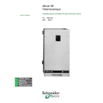
Altivar 68
Telemecanique
Variable speed drives for asynchronous motors
Programming manual
Contents
Installation recommendations ______________________________________________________________ 3
C - Specific functions ____________________________________________________________________ 51
B
E - Adaptation of the drive to installation requirements ________________________________________ 87
E
F - Help function, factory settings, fault memory, configuration and locking code __________________ 99
F
D – Analogue and logic I/O________________________________________________________________ 67
C
B - Initial settings _______________________________________________________________________ 25
D
A - Display of references and actual values and configuration of the display ______________________ 15
A
Control _________________________________________________________________________________ 7
Setup / Maintenance ____________________________________________________________________ 115
Configuration / settings tables ___________________________________________________________ 123
2
This document describes how to configure the Altivar 68.
For connection and setup procedures, also refer to the User's Manual.
The drive’s detection functions (overspeed and veering) must not be used as safety functions if there is a risk
to operating personnel. External safety devices must then be provided for the drive.
When the drive is powered up, the power components and some of the control components are connected to
the line supply. It is extremely dangerous to touch them. The drive cover must be kept
closed.
As a rule, the drive power supply must be disconnected before any operation on either the
electrical or mechanical parts of the installation or machine.
After the ALTIVAR has been switched off, wait for 10 minutes before working on the equipment.
This is the time required for the capacitors to discharge. Check that the voltage between the + and - terminals
is lower than 60 V a .
The motor can be stopped during operation by inhibiting start commands or the speed reference while the
drive remains powered up. If personnel safety requires prevention of sudden restarts, this electronic locking
system is not sufficient : Fit a device to interrupt the supply on the power circuit.
The drive is fitted with safety devices which, in the event of a fault, can shut down the drive and consequently
the motor. The motor itself may be stopped by a mechanical blockage. Finally, voltage variations, especially
line supply failures, can also cause shutdowns.
If the cause of the shutdown disappears, there is a risk of restarting which may endanger certain machines or
installations, especially those which must conform to safety regulations.
In this case the user must take precautions against the possibility of restarts, in
particular by using a low speed detector to cut off power to the drive if the motor is
subject to an unprogrammed shutdown.
Automatic restart :
The drive can be configured to start automatically on power-up. Ensure that no-one is endangered by this type
of start-up.
The products and equipment described in this document may be changed or modified at any time, either from
a technical point of view or in the way they are operated. Their description can in no way be considered
contractual.
The drive must be installed and set up in accordance with both international IEC and national standards.
Bringing the device into conformity is the responsibility of the systems integrator who must observe the
European directives, especially the EMC directive.
The specifications contained in this document must be applied in order to comply with the essential
requirements of the EMC directive.
The Altivar 68 must be considered as a component : it is neither a machine nor a device ready for use in
accordance with European directives (machinery directive and electromagnetic compatibility directive). It is
the responsibility of the end user to ensure that the machine meets these standards.
3
Installation recommendations
Contents
1. Information required before powering up the drive _____________________________________________________________ 4
2. Powering up the drive ___________________________________________________________________________________ 4
3. Minimum setup procedure _______________________________________________________________________________ 4
4. Setting recommendations with an external braking unit connected to the drive (hoisting application) ______________________ 4
5. Autotuning and measurement of motor parameters ____________________________________________________________ 4
6. Setting parameters specific to the application ________________________________________________________________ 4
7. Selecting an application macro ____________________________________________________________________________ 4
8. Adjusting parameters specific to the application ______________________________________________________________ 5
9. Storing parameters _____________________________________________________________________________________ 5
10. Drive control modes ___________________________________________________________________________________ 5
11. Operating with encoder feedback _________________________________________________________________________ 5
4
1. Information required before powering up the drive
• Note the information on the motor rating plate. This will be useful when filling in the "Motor data" menu.
• Refer to the programming manual for how to use the programming keypad (section on “control keypad, menu layout, parameter setting,
setup”).
2. Powering up the drive
• The drive can be powered up in two ways :
- using the line supply to L1, L2 and L3
- using an auxiliary 24 VDC supply connected to terminals P24V and P0V
• Read the setup recommendations in the User's Manual.
The table located above the screen acts as a reminder, allowing quick access to the settings. The current menu is shown at the bottom
left of the screen.
• Line B (B1, B2, etc.) corresponds to the minimum setting required when setting up the device.
3. Minimum setup procedure
When the drive is powered up, the A1 “Home” menu appears.
• Go to B1 and select the language required.
• Go to B3 and enter the motor data on the rating plate : Nominal power, nominal current, nominal voltage, nominal frequency and nominal
speed.
• Select the type of signal for the "auto. reference" (speed reference) : current in D1.04 and voltage in D1.00.
• Return to position A1 “Home” in order to store these parameters.
4. Setting recommendations with an external braking unit connected to the drive
(hoisting application)
• Indicate the presence of a braking unit in C1.03 (external braking unit).
(This avoids auto-adaptation of the deceleration ramp during braking.)
• Select brake logic mode in C6.01 (hoisting or translation).
• Enter the settings as shown in the manual. Do not forget to set the speed error in C6.10.
5. Autotuning and measurement of motor parameters
If the application requires high performance levels, the motor parameters must be measured.
• The power supply must be present at L1, L2 and L3 to perform autotuning.
• Check that no start commands are present on the logic commands.
If the drive is fitted with an I/O extension card, input DI5 must be set to 1 to enable the drive.
• Go to B4.00 to start measuring the motor parameters.
In order to ensure accuracy, the motor must not be rotating during the measurement phase (windmilling fan) and the motor must be cold.
The electrical signals sent to the drive for measuring do not cause the motor to rotate. Autotuning lasts from 2 to 4 minutes, depending
on the size of the motor.
6. Setting parameters specific to the application
Parameters can be set in two ways :
• Either by going directly to the function containing the required adjustment parameter.
Eg : assignment of the selected I/O in D1...D6 and the type of control (local, remote) in E1...E6.
• or using preconfigured settings adapted to the current applications.
These preconfigured settings are called application macros. The drive has 4, corresponding to the principal applications. When an
application macro is selected, the drive adjustment parameters and I/O are automatically adjusted so that they match the type of application
used as closely as possible. This simplifies operation for the user.
The factory configuration is the conveyor macro which is generally used for conveyor type constant torque applications.
The “short menu” in B5 selects (filters) the key parameters of the application, in accordance with the application macro chosen, and all the
parameters modified by the user, ie. those which are different from the factory settings. This menu is used to identify these parameters and
access them quickly. If one of these parameters reverts to the factory setting value, it is removed from the short menu.
7. Selecting an application macro
• The macro is selected using parameter B2.03 “Macro select”.
5
8. Adjusting parameters specific to the application
• Go to the short menu B5 and adapt the settings to the application.
To find out the factory settings for the different macros, refer to the application macro section.
Check that the analogue inputs (references) and logic inputs (run forward and run reverse commands) are configured correctly.
9. Storing parameters
• Store the settings in the drive current memory by returning to the “Home” position in A1 (or use the PC software via parameter A1.00).
This allows storage of the new settings in the drive current memory after a line supply failure. The parameters are also stored
automatically after the drive has been switched on for 5 minutes without interruption.
Caution : If after setting and saving your configuration in the drive current memory, you decide to select a new application macro, the
parameters of the latter will override your previous configuration.
• Store the parameters in one of the two user macros (1 or 2).
The “user macro” is used to store a complete configuration in a specially designated memory area. Two complete configurations can be
stored in B2.01 (USER M1) and B2.02 (USER M2). The parameters of one of the user macros can be used in the drive current
configuration either by configuration (select a user macro in B2.03) or by selection using a logic input (see B2.04).
10. Drive control modes
The drive can be controlled in several ways using :
• the keypad on the programming terminal
• the terminals
• the serial link
• the RS232 link
These control modes can be selected via a logic input assigned to LOCAL/REMOTE control. For purposes of clarity, local mode
corresponds to control via the keypad on the graphic terminal (the drive is controlled by the operator at his machine) and remote mode to
control via the terminals or serial link (the drive is controlled by a PLC).
See the diagram in D2 and selection of control modes in E4.
Reference
• Check assignment of the analogue inputs : choice of a current (D1.04) or voltage (D1.00) reference.
The reference “freq.ref.aut” is programmed on a current input during factory setting. Use of a potentiometer for the reference means that
“freq.ref.aut” must be re-assigned to a voltage input (AIV). The same reference cannot be selected twice (once on the voltage input and
once on the current input). The value must therefore be unassigned before being re-assigned.
With a logic input, 2 different references can be selected : one called MANUAL and one called AUT (see the diagram in D1 and assignment
of a Manual/Aut input in D2). If an I/O extension card is used, input DI5 (disable) must be set to 1 to allow control of the motor.
Run command
▲
▲
• Local control :
The drive can be controlled directly via the keypad on the graphic terminal :
- Press the LOCAL/REMOTE key. Check on the screen that the machine has switched to local mode.
- Press the green RUN key to start and the red STOP key to stop the machine.
- Enter the reference using the keys ▲ ,
and the direction of operation using the keys , .
• Remote control :
Check that the analogue and logic inputs have been correctly selected in A4.00...A4.22 before switching the drive to remote mode. This
prevents transmission of any accidental commands.
• The terminals can be used either locally or remotely depending on how the inputs are assigned (see section D2 on local/remote control).
For example, there is a LOCAL “+speed/-speed” and a REMOTE “+speed/-speed” value.
If the 24V internal supply is used for the logic inputs, it is essential that DIS (common of the logic inputs) is connected to 0V on the
terminals.
▲
11. Operating with encoder feedback
• Set the number of pulses for one rotation of the encoder in D5.03.
• Maintain the drive in calculated speed control with D5.00 on 2 “Encoder” and D5.02 on 0 (closed loop speed control not active).
• Start the motor to check the direction of rotation on the display screen. The frequency reference and feedback must have the same sign
(see D5.03).
• Set the drive to closed loop mode with D5.02 on 1 or 2 (Active) and set D5.04, D5.05, D5.07 and, if necessary, D5.08.
6
7
Control
Contents
The control keypad _______________________________________________________________________________________ 8
Menu layout ____________________________________________________________________________________________ 10
Parameter setting _______________________________________________________________________________________ 11
Local control ___________________________________________________________________________________________ 12
Setup _________________________________________________________________________________________________ 13
8
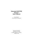
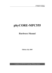
The control keypad
“Reminder”
table for moving
around the menus
Display of
drive status :
Ready, Run or Trip
Configurable liquid
crystal display
screen
“Up” key. For
selecting a menu,
increasing the
numeric values or
the reference in local
mode
f +43.84Hz
Ref+45.6Hz
A1 Remote
P+1045kW
Acceleration
“Right” key. For
selecting a menu,
moving the cursor *
to the right and
controlling the
forward direction of
rotation in local mode
“Run” key in local
mode
“Stop” key in local or
remote mode, can be
programmed for fault
acknowledgement
(reset)
“Local/Remote” key.
Selects control via the
keypad or terminals.
“Left” key. For selecting a
menu, moving the cursor *
to the left and controlling
the reverse direction of
rotation in local mode
“Down” key. For
selecting a menu and
decreasing the numeric
values or the reference
in local mode
* The cursor underlines the modifiable parameter. See “parameter setting” section.
The software version can be read in parameters A3.08 and A3.09.
To select menus using the “up”, “down”, “left” and “right” keys, the “reminder” table must be used.
9
“Menu/parameters”
key used to access
the parameter
settings or quit adjust
mode to return to the
menu
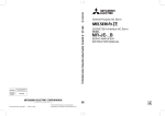
The control keypad
Shortcut keys
Top left (A1-Display)
press simultaneously
Top right (A6-Display Configuration)
press simultaneously
Bottom left (F1-Test-Help)
press simultaneously
Bottom right (F6-Code Lock)
press simultaneously
Adjusting the display contrast
The LCD display contrast is adjusted using the potentiometer in the top left-hand corner
of the control card.
LCD
contrast
-
+
10
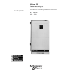
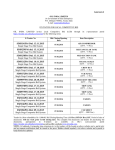
Menu layout
The 3-D view shows the menu layout and access to the adjustment parameters.
A, B, C, D, E, F define the groups of related menus : A Display menus, B Setup menus etc
MENUS
1
A
Display
Home
B
Initial SetC
Adjustment
D
I/O
2
Motor
Values
Language
Macro
Selection Configuration
General
Functions
Ramps
3
Inverter
Values
4
Reference
Values
Display
Configuration
Motor
Data
B3.00
Logic
Inputs
B3.02
Group of
parameters
from menu B3
B3.03
B3.04
Drive
Overload
F
Diagnostics
Time
kWh
6
B3.01
Analogue
Inputs
E
Drive
5
Display screen :
ref + 50 Hz
Test-Help
I=00A
B3
Motor data
Nominal freq.
B 3.03=
50 Hz
B3.03
Nominal freq.
VICB
25.00…50.00…300.0 Hz
Factory setting
Max. value
or Value set
Identification of parameters :
Can only be modified if access enabled (1)
Can be modified if unlocked by access code (2)
Can be modified if stopped (speed drive disabled) (3)
Parameter can always be modified
Min. value
MENU
Parameter name
Parameter number
• The menu parameters are accessed using the Menu/Param. key.
• The A1 Home menu performs a special function :
It does not contain any parameters but shows the basic display. Modified values are stored by switching to the basic display (Menu/
Param. key).
Modified values are stored by :
- switching to the A1 Home level
- or they are stored automatically 5 minutes after the parameter has been modified (drive switched on).
• Each menu can be accessed using the arrow keys.
(1) See parameter F6.02
(2) See parameters F6.00 and F6.01
(3) A run command cannot be executed while this parameter is being modified.
Commands sent by the keypad are ignored and logic commands are suspended if the cursor is to the right of the "=" sign.
11
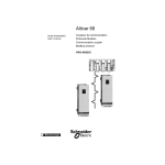
Parameter setting
Note that pressing the keys changes the menu or the underlined parameter.
f + 50.00 Hz
Ref +50.0Hz
Return to A1 Home.
This stores the modified
parameters in the drive
memory.
A1 Local
I=300 A
f=f ref.
Access to menus
f + 50.00 Hz
I=300A
A1 Home
Change menu to A1
Go to menu C2
f + 50.00 Hz I=300 A
C2
Ramps
Access the parameters of
menu C2
Exit the parameter group
f + 50.00 Hz I=300 A
C2
Ramps
Accel. ramp 1
C200= 10.0s
Scroll through the parameters
within the menu
Scroll through the parameters
within the menu
f + 50,00 Hz I=300 A
C2
Ramps
Decel. ramp 2
C203= 20.0s
Move the cursor to
the parameter number
Move the cursor to
the parameter value
f + 50.00 Hz I=300 A
Parameter setting can be
terminated using the MENU/
PARAM. key.
C2
Ramps
Decel. ramp 2
C203= 20.0s
Modify the parameter value
with immediate effect
Move the cursor to the tens
digit
f + 50.00 Hz I=300 A
C2
Ramps
Decel. ramp 2
C203= 25.0s
12
Local control
In order to control the drive from its built-in keypad, the “local” operating mode must be activated.
Use the “LOCAL/REMOTE” key on the programming keypad to switch to “local” mode.
The following keys are then active :
Keys
Keypad
Menu
Parameter group
Start-up
---
---
Stop/Reset
Stop/Reset
Stop/Reset
Increase the reference
Go to menu
Scroll through parameters or increase their
value
Decrease the reference
Go to menu
Scroll through parameters or decrease their
value
Rotate left
Go to menu
Move the cursor to the left
Rotate right
Go to menu
Move the cursor to the right
If the permanent contacts FWD (run forward) or REV (run reverse) are activated on the terminals, the motor will restart
automatically after correction of a fault and resetting.
The local operating mode can be locked by using parameters E4.00, E4.01 and E4.03.
If I/O extension card 1 is used, a high state (logic 1) on terminal DI5 is always necessary to start the motor.
If parameter E4.03 is set to 1 "Terminals" the keys of the control keypad then have no function in local mode (exception : “Stop
key”, if parameter E4.04 is set to “1 always active”).
13
Setup
Set up the drive in the following order :
B
Initial SetLanguage selection
Selects the language displayed
Macro Configuration
Selects a macro-program to configure the terminals
and transfers the parameters relevant to your
application to a short menu.
Motor Data
Two alternatives are defined depending on the
specifications of your application :
High torque : high overload (1.5 In)
Standard torque : limited overload (1.2 In)
Auto tune
Measures the motor parameters and autotunes the
drive in accordance with the motor specifications.
Short Menu
Selects the “key” parameters of the application
macro selected and any parameters which are
different from the factory setting.
B1
B2
B3
B4
B5
Matrix
If additional parameters necessary for optimization of the
installation are not in the short menu, they can be selected from
one of the menus and then set. They are then automatically
added to the short menu.
Macro Configuration
B2
On completion of setup, the parameter settings can
be stored in a user macro via parameters B2.01 and
B2.02.
Do not forget to go back to the “A1” basic display to store the parameters.
Powering the drive with an auxiliary 24 VDC supply is very useful during setup. This means that settings can be adjusted without switching
on the power component of the Altivar 68 (exception : Autotuning and factory settings).
The user interface is fully operational with this auxiliary voltage.
The settings can be written down on the special forms designed to assist with setup (see “Configuration / settings tables”, page 124).
Make a note of all the parameters shown in the short menu and their values. These are the only parameters which differ from the factory
settings.
14
15
Display of references and actual values
and configuration of the display
A
Contents
A1. Home______________________________________________________________________________________________ 16
A2. Motor values ________________________________________________________________________________________ 18
A3. Inverter values_______________________________________________________________________________________ 19
A4. Reference values ____________________________________________________________________________________ 20
A6. Display configuration__________________________________________________________________________________ 23
16
A
A5. Time / kWh _________________________________________________________________________________________ 22
A1. Home
Modified values are stored in the drive memory by :
1. Switching to the basic display level (A1 Home)
2. Or they are stored automatically 5 minutes after the parameter has been modified.
This menu is the drive’s basic display. 3 analogue values, the control mode, the drive status and the menu are shown.
f + 32.50 Hz
Active menu
Ref +50.0Hz
I=300 A
Analogue values
A1 Local
Acceleration
Current status of drive
A
Control mode (1)
The analogue values to be displayed can be selected from menu A6 (Display Configuration). All parameter modifications will be stored by
returning to menu A1 “Home”.
Status
Comment
Disabled
The drive is disabled if the enable command on the control terminals is not present (factory setting : input DI5_2 on
the option card or programmable logic input) or if the drive is locked by the communication bus “step 0, Not Ready
to Switch on” and “step 19, Lock switching on”.
Stop
The drive is unlocked and waiting for a run command (run command and speed reference).
Not enabled
Only for the communication bus. If the command “bit 3 operation authorization” is missing.
Trip
The drive is faulty. The fault is shown on the screen.
Loading
This shows that the capacitors are currently charging. This information is only available when the 24VDC supply is
used on the drive and the latter is controlling the line contactor.
Mains off
The drive is switched off (L1, L2 and L3) by the line contactor which is itself controlled by the drive (line contactor
control C6.00).
Mains miss.
“Mains missing” is displayed if the line supply fails while the motor is running and the time delay for appearance of
the undervoltage fault (programmed in E3.09) has not elapsed.
Mains disc.
This is displayed if the logic input programmed on "mains ON/OFF” is enabled. The line contactor opens for safety
reasons.
Locked
Only local control is authorized. Control via the terminals is not authorized unless the logic inputs of the terminals are
programmed to local control (run command and speed reference). Control via the graphic terminal : authorized.
Control via the communication bus : not authorized.
Autotuning
The autotuning function is active.
(1) Control mode :
The control mode can be local or remote, see E4 for more details.
17
A1. Home
Display during operation
• The drive accelerates in accordance with the acceleration ramp selected. The frequency reference has not yet been
reached (fref > fact): frequency reference > stator frequency.
• The stator frequency has decreased due to active limitation (drive overload, motor overload, switch to torque or
current limiting, etc) when the motor is running (fref > fact).
• The drive is operating with limited torque when the motor is running (fref > fact).
Deceleration
• The drive decelerates in accordance with the deceleration ramp selected. The frequency reference has not yet been
reached (fref < fact).
• The frequency has increased due to active limitation (drive overload, motor overload, switch to torque or current
limiting, etc) when the generator is running (fref < fact).
• The drive is operating with limited torque in regeneration mode (fref < fact)
f = f ref.
The actual frequency is the same as the frequency reference.
Hysteresis and time can be adjusted using parameter D4.08.
USER Macro 1
User macro no. 1 (motor 1 parameters) is being used and the logic input is at 0. When parameter B2.04 is selected
on “PAR 1/2” (1 motor) or “PAR 1/2” (2 motors).
USER Macro 2
User macro no. 2 (motor 2 parameters) is being used and the logic input is at 1. When parameter B2.04 is selected
on “PAR 1/2” (1 motor) or “PAR 1/2” (2 motors).
Warnings and
limitations
See “Faults - causes - remedies”, page 119. (only if A6.03 = 1).
A
Acceleration
Display during parameter setting
Code
The user is trying to set a parameter which can only be accessed with a code.
Unlock F6!
Para locked
1. The user is trying to modify a parameter which can only be accessed via the logic input “para-locked” (see D2.10
number 35).
2. The user is trying to modify a parameter while parameter B2.04 is selected on “PAR 1/2”. Set parameter B2.04 to
“0 not active”.
Not locked
The user is trying to set a parameter which can only be modified when the drive is locked. Send a stop command.
Paramet-Access
The user is trying to set a parameter using an unauthorized access code. Authorize access (see F6.02 ParametAccess : keypad, bus or RS232).
Read only
The user is trying to set a parameter which cannot be modified (display).
18
A2. Motor values
Display of actual drive (motor) values
A2.00
Speed [rpm] (signed value)
Read only (1)
Shows the actual speed in revolutions per minute, even when the drive is locked, ie. when the motor is freewheeling.
The values are negative when rotating to the left.
A2.01
Torque [Nm] (signed value)
Read only
Display as a function of the 4 quadrants. Display accuracy : ±5% of the nominal torque
A2.02
Motor load [%]
Read only
A
100 % refers to the nominal motor current. Display accuracy : ±1,5%.
A2.03
Motor current [A]
Read only
Motor rms current in amps. Display accuracy : ±1.5% of the nominal current
(rms value of the fundamental of the nominal current)
A2.04
Shaft power [kW] (signed value)
Read only
Mechanical power on the motor shaft. Display accuracy : ±5% of the nominal power (calculated as a function of speed
and torque)
A2.05
Appar. power [kVA]
Read only
Apparent power of the motor. Display accuracy : ±3% of the nominal power
(calculated as a function of current and voltage)
A2.06
Motor voltage [V]
Read only
Display accuracy : ± 2% of the nominal voltage (rms value of the fundamental)
A2.07
Slip frequency [Hz] (signed value)
Read only
Calculated from the load as a function of motor nominal slip.
(calculated from the torque and flux)
A2.08
Linear speed [m/min] (signed
value)
Read only (1)
Option to display the linear speed of the installation in m/min using a conversion factor with parameter A2.10. (A2.08
= A2.00 x A2.10)
A2.09
Rot. speed [rpm] (signed value)
Read only (1)
Option to display the rotation speed of the installation in rpm. The reduction ratio is entered in parameter A2.11. (A2.09
= A2.00 x A2.11)
A2.10
Process scaling
VCB
-10.00…1.000…10.00
A2.11
Machine scaling
VCB
-10.00…1.000…10.00
(1) If the power is not switched on (“Mains miss.” or “Mains off” on the screen), these actual values equal 0.
19
A3. Inverter values
Display of actual drive values
A3.00
Output freq. [Hz] (signed value)
Read only
Drive output frequency. Resolution : 0.01 Hz
A3.01
Drive load [%]
Read only
Load STATE of the drive, 100 % refers to the drive nominal current ("High torque" version). Display accuracy : ±1.5 %
of the nominal current (“High torque” version).
A3.02
DC voltage [VDC]
Read only (1)
A3.03
Heatsink temp. [°C]
A
Shows the actual voltage of the intermediate circuit (DC bus). Display accuracy : ±2 % of the max. voltage
• 400 / 500 V range : The maximum voltage is 920 VDC.
• 690 V range : The maximum voltage is 1200 VDC.
Read only (1)
Display accuracy : ±5 %
Too high a temperature results in the following, from 80°C for a frequency > 10 Hz and from 60° for a frequency < 10 Hz :
1. a reduction in the switching frequency (see E6)
2. a reduction in the current limit value
3. tripping because the temperature is too high (at 100°C).
A3.04
Switching freq. [kHz]
Read only
Switching frequency
A3.05
Drive reference
Read only
Drive reference : ATV68CxxN4
A3.06
Nom. current "C" [A]
Read only
Drive nominal current
A3.07
Hardware vers.
Read only
Upgrade index of the power component
A3.08
Software type
Read only
A3.09
Software vers.
Read only
A3.10
Serial no.
Read only
Drive serial number, determined by the central card
A3.11
Drive status
Read only
See also Profibus option guide (same as B6.48).
10 . . . Crane active
0 . . . . Not Ready ON
11 . . . JOG1 active
1 . . . . Rdy. switch ON
12 . . . JOG1 pause
2 . . . . Load DC bus
13 . . . OFF1 active
3 . . . . Ready to run
14 . . . OFF3 active
4 . . . . Oper. release
15 . . . Close brake
5 . . . . Ramp enable
16 . . . DC-brake 1
6 . . . . Ramp release
17 . . . DC-brake 2
7 . . . . Run
18 . . . OFF2 active
8 . . . . Mot. fluxing
19 . . . Lock switching on
9 . . . . Rel. brake 1
20 . . . Trip
21 . . . Auto tune
22 . . . Power test
23 . . . Rel. brake 2
24 . . . Rel. brake 3
(1) If the power is not switched on (“Mains miss.” or “Mains off” on the screen), these actual values equal 0.
20
A4. Reference values
Reference values
Filter
Analogue
input
A
D
Max. value
mA / Hz / %
Min. value
0 mA
4 mA
AIV
AIC
AI Scaled ref.
A
Reference value after analogue / digital
conversion and adjustment (0 to 100 %)
A4.00
AIV 0...10 V [%]
Reference value in Hz depending
on the reference range used,
limited by the minimum and
maximum values
Read only
Reference at analogue input AIV terminals (0 V...10 V = 0 %... 100 %).
A4.01
AIV scaled [Hz] ([%])
Read only
Reference and scaling of AIV input.
A4.02
AIC 0(4)...20 mA [%]
Read only
Reference at analogue input AIC terminals (0(4) mA... 20 mA = 0 %... 100 %)
A4.03
AIC scaled [Hz] ([%])
Read only
Reference and scaling of AIC input.
A4.04
AI_2 0(4)...20 mA [%]
Read only
Reference at analogue input terminals (AI+, AI-) of the optional I/O card
(slot X2) (0(4) mA... 20 mA = 0 %... 100 %)
A4.05
AI_2 scaled [Hz] ([%])
Read only
Reference and scaling of AI_2 input.
A4.06
AI_3 0(4)...20 mA [%]
Read only
Reference at analogue input terminals (AI+, AI-) of the optional I/O card
(slot X3) (0(4) mA... 20 mA = 0 %... 100 %)
A4.07
AI_3 scaled [Hz] ([%])
Read only
Reference and scaling of AI_3 input.
A4.08
Pre-set ref. [Hz] ([%])
Read only
Preset reference currently enabled.
A4.09
Local ref. [Hz] ([%])
Read only
Reference from graphic terminal or terminals but via logic inputs (+speed/-speed).
A4.10
Remote ref. [Hz] ([%])
Read only
Reference from terminals or communication link.
A4.11
Freq. before ramp
Read only
Frequency reference before the ramp.
A4.12
Freq. after ramp
Frequency reference after the ramp.
21
Read only
A4. Reference values
A4.13
Max. torque ref. [%]
Read only
Maximum torque reference.
A4.14
Digital inp. X1
Read only
This parameter shows the state of the logic inputs on terminals 11 to 14 of terminal block X1, written from right to left.
A4.15
Digital inp. X2
Read only
A4.16
Digital inp. X3
Read only
This parameter shows the state of the logic inputs on terminals 26 to 29 of terminal block X3 (I/O option card), written
from right to left.
A4.17
BUS CTRL word
Read only
Displays the drive control word in bus mode (see programming guide of the communication protocol).
A4.18
Bus ref. 1 scale
Read only
Displays reference 1 which has been scaled by the communication link. Therefore given in Hz or as a %.
A4.19
Bus ref. 2 scale
Read only
Displays reference 2 which has been scaled by the communication link. Therefore given in Hz or as a %.
A4.20
Bus ref. 3 scale
Read only
Displays reference 3 which has been scaled by the communication link. Therefore given in Hz or as a %.
A4.21
Bus ref. 4 scale
Read only
Displays reference 4 which has been scaled by the communication link. Therefore given in Hz or as a %.
A4.22
Bus ref. 5 scale
Read only
Displays reference 5 which has been scaled by the communication link. Therefore given in Hz or as a %.
Parameters A4.18 to A4.22 show the BUS references (PZD2 to PZD6) in the form of standardized values (physical measurements in Hz
or as a %) instead of hexadecimal values. For more details, see the instructions for the Profibus option.
22
A
This parameter shows the state of the logic inputs on terminals 26 to 29 of terminal block X2 (I/O option card), written
from right to left. NOTE : When the I/O card is not used, logic input 26 (or DI5 on X2) is automatically written to 1 (in
order to authorize switching of the drive to Run)
A5. Time / kWh
Display of actual drive values
A5.00
Oper. hrs motor [h]
Read only
Counter totalling the number of motor operating hours (corresponding to an unlocked drive). (Information visible on
the screen - see A6.00 to 02)
A5.01
Operat.hours FI [h]
Read only
Counter totalling the number of drive operating hours (corresponding to a drive powered by mains or 24V supply).
A5.02
kWh meter [MWh]
Read only
A
Counter totalling the energy consumed by the motor in MWh (active power).
Tolerance given at ±3 % (Information visible on the screen : see A6.00 to A6.02).
Parameters in hours and MWh cannot be reset to 0.
23
A6. Display configuration
Configuration of the basic display A1
Dynamic or analogue reference values can be assigned to zones 1, 2 and 3. Double
assignment is not possible.
Area 1
Area 2
Menu
The status area is used to display the status of the drive.
Area 2
Control mode
Status
Ref +50.0Hz
I=300 A
A1 Local
Acceleration
A6.00
Select zone 1
VCB
Output frequency
A6.01
Select zone 2
VCB
Internal frequency reference
A6.02
Select zone 3
VCB
Motor current
0...f
1 . . . L-FI
2 . . . C-Mo
3...T
4...V
5...I
6...P
7...S
8...n
9...10 . . n
11 . . Ref
12 . . T
13 . . W
14 . . X
15 . . W-X
16 . . Udc
17 . . tMo
18 . . W
19 . . IA
A6.03
Hz
% of drive nominal current at constant torque
% of motor nominal current
Nm
V
A
kW
kVA
rpm
m/min
rpm
Hz
%
%
%
%
V
h
MWh
A (not for A6.01)
Output frequency
Inverter load status
Motor load status
Torque
Motor voltage
Motor current
Shaft power
Apparent motor power
Motor speed
Installation linear speed
Installation rotation speed
Ref. val before ramp
Torque reference
PID reference
PID feedback value
W-X error
DC bus voltage
No. of motor operating hours
Motor consumption
Autotun. current
View limitation
VCB
A
f + 32.50 Hz
Example :
A3.00
A3.01
A2.02
A2.01
A2.06
A2.03
A2.04
A2.05
A2.00
A2.08
A2.09
A4.11
A4.13
C4.00
C4.01
C4.02
A3.02
A5.00
A5.02
B4.05
not visible
0 . . . not visible
1 . . . visible
If the parameter is set to 1, the internal values currently being limited are displayed. Example : “current limit” when the
drive current is limited during acceleration. The display appears if limitation is effective for at least 1.5 seconds.
24
A
25
Initial settings
B
Contents
B1. Language selection ___________________________________________________________________________________ 26
B2. Macro configuration___________________________________________________________________________________ 27
B3. Motor data __________________________________________________________________________________________ 29
B4. Auto tune___________________________________________________________________________________________ 30
B5. Short menu _________________________________________________________________________________________ 31
B
B6. Communication menu _________________________________________________________________________________ 50
26
B1. Language selection
Selection of the dialogue language
B1.00
Select language
VCB
0 . . . German
1 . . . English
2 . . . French
3...
4...
German
English
French
Spanish*
Italian*
B
This parameter is not modified if the factory settings are used.
27
French
*Not yet available
B2. Macro configuration
Selection of an application macro
B2.00
Macro selected
Read only
B2.01
Store USER M1
VCB
B2.02
Store USER M2
VCB
0 . . . Initial state 0, Start 0 -> 1
1 . . . Storing
2 . . . Stored
Set to 1 for storage, Modifiable parameter
Read only
Read only
B2.01 (B2.02) is used to store a configuration in a designated memory area called “User Macro 1” (User Macro 2).
Adjustment procedure : Select the application macro in B2.03. The application macro is a factory setting of all the
parameters specific to the application in question. The parameters specific to the application appear in the short menu.
If some parameters have to be modified, this can be done in the short menu or in the other menus. All the new modified
parameters will be added automatically to the short menu. This new configuration is stored in the user macro using
“Store USER M1 or M2”.
The motor data and the autotuning parameters are also stored (Menus B3 and B4)!
The parameters stored in the user macro can be loaded using parameter B2.03 (including the motor data and
autotuning parameters) or via logic input B2.04.
This can be useful if the power component is changed (power block).
Caution : An application macro cannot be modified.
B2.03
Macro select.
VICB
Conveyor
0 . . . Conveyor
1 . . . Piston pump
2 . . . Centrifugal pump
3 . . . Coiler
4 . . . Test bench
5 . . . Pump & PID controller
6 . . . Exhaust fan
7 . . . Fan
8 . . . Separator
9 . . . User macro 1
10 . . User macro 2
Macro M1 (page 33)
Macro M1 (page 33)
When an application macro is
Macro M2 (page 37)
selected, the existing parameters are
Macro M4 (page 46)
replaced by the parameters of the
Macro M4 (page 46)
application macro. The motor data is
Macro M3 (page 41)
not replaced.
Macro M2 (page 37)
Macro M2 (page 37)
Macro M1 (page 33)
When user macro 1 or 2 is selected, the existing parameters are
replaced by the parameters of the user macro, including the motor
data. It is therefore possible to keep 2 different motor configurations.
Quit the menu without selecting a macro
11 . . No change
To make it easier to adapt the drive to your requirements, a large number of application macros has been stored in the
“Library”. Selecting a macro automatically activates the appropriate functions, with optimum parameter setting and
configuration of terminals. A short menu is created at the same time, containing each parameter required for this
application. For a detailed description of the macros, please see “Short menu” in B5.
Caution : The factory settings of user macros 1 and 2 do not contain motor data. It is essential to perform either
an autotuning operation or load the factory settings of a standard motor corresponding to the drive rating (see
F2-01).
28
B
Display of the application macro used.
In the case of a User Macro (UM), this display also shows which application macro the user macro has come from.
B2. Macro configuration
B2.04
Multi-config.
VCB
0 . . . Not active
1 . . . Par 1/2 (1 motor)
Not active
Selection of user macro 1 or 2 via logic input. Application with a single
motor (a single thermal calculation for user macro 1 and 2).
Selection of user macro 1 (equivalent to motor 1) or user macro 2
(equivalent to motor 2) via logic input. Application with 2 motors (one
thermal calculation for each macro and for each motor).
2 . . . Par 2/2 (2 motors)
memory
macro M2
B2.03
macro M3
macro M4
Logic input
user macro 2
user macro 1
(motor data included)
B
macro selection
macro M1
user macro 2
(motor data included)
B2.01
0
1
2
0
B2.02
1
2
0
1
2
0
1
2
Mains
B2.04
3
Current configuration used for the drive
Drive memory
3
M1
M2
B2.01 (and B2.02) : storage of the current drive configuration in user macro 1 (and 2).
To store a configuration in a user macro, B2.04 must be set to 0 “not active”.
By selecting 1 or 2, a logic input (configure D2.xx to 20, select user macro 2) can be used to select user macro 1 or 2.
The choice of user macro thus depends on the logic input DIx assigned to D2.xx.
1. Select the application macro for the first motor, set the motor data, perform an autotuning operation (if necessary)
and set all the parameters required for the application.
2. Select a logic input (parameter D2.00 to D2.10) at position 20 (select user macro 2 or 1).
3. Use B2.01 to store the parameters set on user macro 1.
4. Connect the second motor, set the motor data, perform an autotuning operation (if necessary) and set all the
parameters required for the application.
5. Select the same logic input as for user macro 1 (parameter D2.00 to D2.10) at position 20. (Select user macro 2.)!
6. Use B2.02 to store the parameters set on user macro 2.
7. Set parameter B2.04 to 1 “Par 1/2 (1 motor)” or 2 “Par 1/2 (2 motors)” and return to A1 to store the configuration.
8. Depending on the position of the logic input selected in 2) or 5), user macro 1 or 2 is loaded into the current
configuration if the drive is locked (Stop, Mains miss. with 24VDC supply). The current user macro is displayed on
the screen.
Logic input at 0 = User Macro 1: display “USER Macro 1”.
Logic input at 1 = User Macro 2: display “USER Macro 2”.
9. Set parameter B2.04 (multi-config.) to 0 to modify the configuration of the user macro again.
Then store the new configuration using parameter B2.01 or B2.02. Set parameter B2.04 to 1 or 2 again.
If B2.04 stays at 1 or 2, the parameters of the user macros cannot be modified.
29
B3. Motor data
Entering data from the motor rating plate
B3.00
Nominal power [kW]
VICB
0...motor power..2500 kW
Enter the power value shown on the motor rating plate.
B3.01
Nominal current [A]
VICB
0...motor current..2500 A
Enter the nominal current value shown on the motor rating plate.
B3.02
Nominal voltage [V]
VICB
0...voltage...1000 V
Enter the voltage value shown on the motor rating plate.
B3.03
Nominal freq. [Hz]
VICB
25..frequency..300 Hz
Enter the frequency value shown on the motor rating plate.
Nominal speed [rpm]
VICB
0...speed...18000 rpm
Enter the speed value shown on the motor rating plate.
Notes :
1. The factory setting for parameters B3.00 to B3.04 corresponds to a 4-pole motor and to the motor power of
the drive used with standard torque (eg. ATV-68C33N4, Pn = 315 kW).
If the motor used is different, these parameters must be modified.
The nominal speed set must be lower than or equal to the synchronous speed. If it is higher, the drive
will calculate the wrong number of poles and the value on the display screen will be incorrect.
2. If the drive is used with "high torque", the settings must be re-entered.
3. To operate a 50 Hz motor at constant torque ("delta" connection) up to 87 Hz, the settings must be reentered. Eg : 230 V/400 V, 110 kW, 50 Hz motor
B3.00 = Pn • √3 = 110 • √3 = 190.5 kW
B3.01 = Inominal ("delta" connection 230 V) = 270 A
B3.02 = Un ("star" connection) = 400 V
B3.03 = fn • √3 = 50 • √3 = 87 Hz
B3.04 = Nn • √3 = 1460 • √3 = 2530 rpm
B3.05
0....3....3
Line voltage (V)
VICB
0 . . . 400 V; 50/60 Hz
1 . . . 440 V; 60 Hz
2 . . . 460 V; 60 Hz
3 . . . 500 V; 50 Hz
4 . . . 690 V; 50 Hz
400V ± 15%, 50/60Hz ±5%
440V ± 10%, 60Hz ±5%
460V to 480V ± 10%, 60Hz ±5%
500V -15% +10%, 50Hz ±5%
690V ±10%, 50Hz ±5%
• Positions 0 - 1 - 2 - 3 are for the ATV-68 400 / 500 V range.
Enter the value of the line voltage.
An incorrect value may result in an error message (undervoltage) during operation or damage to the rectifier bridge if
there is a mains break on a line of a higher value than the value set (charging of capacitors without the charging
resistor). The voltage selected in B3.05 automatically adjusts the undervoltage level.
• Position 4 is for the ATV-68 690 V range only.
Caution : This parameter is not modified if the machine reverts to the factory settings.
B3.06
Overmodulation
VICB
not active
0 . . . Not active
1 . . . Active
If B3.06 is set to 1, the drive supplies the maximum output voltage possible to offset the voltage drop of 2 to 3% caused
by the line choke. However, in this case the current harmonics are higher.
B3.07
Output filter
VICB
not used
0 . . . Not used
1 . . . Used
If a motor choke is used.
With output filter (not yet available).
Note : The encoder feedback option cannot be used with the output filter.
30
B
B3.04
B4. Auto tune
Exact adaptation between the drive and the motor
B4.00
Autotuning
VICB
0 . . . Start 0 -> 1
1 . . . Autotuning
2 . . . Rotor coeff.
3 . . . Rot. time const.
4 . . . Stator R
5 . . . I-flux 1
6 . . . I-flux 2
7 . . . I-flux 3
8 . . . I-flux 4
9 . . . I-flux 5
10 . . O.K.
Initial state 0, switch to 1 with ▲ key to start autotuning.
Start of autotuning.
Calculation of a rotor leakage coefficient and automatic loading.
Calculation of the rotor time constant.
Measurement of the winding and cable resistance.
Calculation of the flux current in 5 steps.
11 . . Stop
Autotuning is complete and the motor data is sent to parameters B4.01
to B4.04.
Autotuning stops if the “Stop” key on the keypad is pressed.
B
The motor does not rotate during the autotuning procedure. Autotuning lasts from 2 to 4 minutes, depending on the size
of the motor.
1. The drive must be unlocked (“Stop” showing on the screen) to perform autotuning (if an option card is
present, enable input DI5).
2. The motor must not rotate during the autotuning phase (connected to an external unit, eg. fan)!
3. Voltage on L1, L2 and L3 must be present.
4. The motor must be cold.
Caution :
If an output filter is used, open connections X16 and X18 between the drive and the output filter!
(Not applicable for a motor choke).
Note : There may be several reasons why an error message appears during autotuning :
Message “12 Err.rotor k” :
Possible cause :
• Drive locked, see input DI5 on option card or bus control.
• Motor not connected.
Message “13 Err.rot.tc” :
Possible cause :
• Motor power too high.
Message “14 Err.stat.R” :
Possible cause :
• Motor not connected.
Message “15 Error:I-flux” :
Possible cause :
• Motor data (B3.00 to 04) not correct.
• The motor is rotating during autotuning.
If the motor does not operate correctly after autotuning (eg. in the case of special motors), it is possible to return just
the autotuning parameters to the factory settings. Use F2.01 “Ret. fact. motor”.
B4.01
Rotor coeff.
VICB
0...depending on rating...99999
B4.02
Rot. time const.
VICB
0.000...depending on rating...4.000 s
B4.03
Stator R
VICB
0.00..depending on rating. 20000.00 mOhm
B4.04
I-flux
VICB
0.0...depending on rating..2500 A
When the drive is delivered or after using F2.01 to return to the factory settings, motor parameters B4.01 to B4.04
correspond to a 4-pole motor with the same power as the drive used with standard torque (eg. ATV68C33N4,
Pn = 315 kW).
These values are modified after autotuning and can be reset manually.
These parameters must only be modified by specialists.
B4.05
I autotuning [A]
Read only
The current can be displayed during autotuning.
➞ See also parameters A6.00 to A6.02.
31
B5. Short menu
Adjustment of parameters in the short menu
The parameters for an application appear in the short menu according to the application macro selected.
In many cases, the definition or adaptation of only those parameters contained in the short menu will be sufficient.
If optimization is then required, for example, when an optional card or certain additional functions are used, the menus are used to modify
the necessary settings.
These modifications will then appear in the short menu.
Parameters are moved automatically to the short menu which gives a quick overview of the settings. Parameters whose value is the same
as the factory setting are not shown in the short menu.
B5.
Short menu (before)
For example, modification of parameter C1.02
B5. Short menu (after)
C1.00
Inc. start Tor.
C1.02
➞
C1.14
C2.00
C2.01
C3.00
Economy mode
Acceleration…
Deceleration…
Low speed
C1.00
C1.02
C1.14
C2.00
C2.01
C3.00
Deceleration
The setting changes to :
Inc. start Tor.
Stop mode
Economy mode
Acceleration…
Deceleration…
Low speed
The short menu contains the principal parameters of the application (according to the Configuration Macro selected) and those parameters
which have been modified by the user and are different from the original factory setting.
It is used to access the settings quickly. It selects (and filters) all the adjustment parameters.
32
B
Stop mode
0 Freewheel stop
1 Deceleration
2 Fast stop
B5. Short menu
Macro M1 - Motors with high overload (factory setting)
Conveyors
Piston pumps
Vertical hoisting and horizontal movement
Separators, etc
The starting torque can be set up to a maximum of 180% for difficult starts (parameter C1.00 “Inc. start Tor.”).
The references are preset remotely at 4-20mA and local control is obtained via the keypad of the graphic terminal.
The drive logic inputs are assigned to :
• Forward
• Reverse
• Controlling a second ramp
• Resetting faults
All the parameters can be reset using the different menus.
The modified settings can be stored in the user macro. All the modified parameters are automatically stored in the short menu where they
are arranged in order.
Connection diagram
X1 :
Voltage for analogue references
AIV 2
"Voltage" analogue input
Reference
4…20 mA
AIC 3
"Current" analogue input
0V 4
Ground
Output frequency
image signal
AO1 5
B
+10 1
0V 6
4…20 mA
Ground
TH+ 7
TH- 8
Thermistor input
0V 9
Ground
DIS 10
Common feedback
Start FWD
DI1 11
Start REV
DI2 12
Ramp 2
DI3 13
EXT reset
"Current" analogue output
Logic inputs
DI4 14
+24 15
Logic input power supply
P24 16
P0V 17
External supply voltage
RL1 18
Drive
"Ready + Run"
NC1 19
NO1 20
X2 : Option IO 1
X3 : Option IO 1
33
Output relay
B5. Short menu
Short menu for macro M1
Name
Setting
Note
B2.03
Macro select.
Conveyor
or : Piston pump, Separator
C1.00
Inc. start Tor.
0...1...30 %
The starting torque can be increased from 150 to 180 %
C2.00
Accel. ramp 1
0.0...5.0...3200 s
Setting in seconds for the nominal motor frequency
C2.01
Decel. ramp 1
0.0...5.0...3200 s
Setting in seconds for the nominal motor frequency
C3.01
Max. frequency
25.00...50.00...300 Hz
Setting for the upper frequency limit
C3.02
Dir. Enable
Enable FW/RV
Permits forward and reverse directions of rotation
D1.04
AIC-selection
Freq.ref.aut
Automatic frequency reference on input AIC in mA
D1.06
AIC value 0%
-300.0...0.00...300.0 Hz
Determines the frequency for 0 % of AIC
D1.07
AIC value 100%
-300.0...50.00...300.0 Hz
Determines the frequency for 100 % of AIC
D2.00
DI1-selection
Start FWD
Forward/Stop (permanent contact)
D2.01
DI2-selection
Start REV
Reverse/Stop (permanent contact)
D2.02
DI3-selection
Ramp 2
Switches to the second set of acceleration and deceleration
ramps
D2.03
DI4-selection
EXT reset
External fault reset (normally open fleeting contact)
D3.00
AO1-selection
|f-out|
Analogue output no. 1 - Value of the frequency generated
4-20 mA = 0-fmax
D4.01
Relay output 1
Ready + Run
Ready on RL1
E2.00
Thermistor input
not active
E2.02
I.max. at 0 Hz
0...50...150 %
I2t motor protection, maximum current at frequency of 0 Hz as
a percentage of the nominal motor current
E2.03
I.max. at f.nom
0...100...150 %
I2t motor protection, maximum current at nominal frequency as
a percentage of the nominal motor current
E2.05
Motor-tme const
0...5...3200 min
If > 5 min, the 24 V external supply is necessary
B
Parameter
Note : All the motor data (matrix field B3) is displayed in the short menu.
34
B5. Short menu
Additions to macro M1
Rounded deceleration and acceleration ramps
A rounded ramp profile can be set in order obtain a smooth transition from motor stopped to motor acceleration phase and then to a fixed
number of revolutions.
S-ramp
U-ramp
Reference
Reference
C2.05 = 0
C2.04 = 0
1 2
C2.05 = 1
t1 = C2.00 to C2.03
k = 1 : t2 = 1.1 x t1
k = 2 : t2 = 1.25 x t1
k = 3 : t2 = 1.5 x t1
3
0
C2.04 = 0
1
2
t1 = C2.00 to C2.03
k = 1 : t3 = 1.05 t1
k = 2 : t3 = 1.125 t1
k = 3 : t3 = 1.25 t1
3
0
t
t1
t
t1
t2
t3
B
Parameter modifications necessary in addition to macro M1 :
Parameter
Name
Setting
Note
C2.04
S-ramp
S-ramp step 1, 2 or 3
Selection according to requirement
C2.05
S-ramp mode
Begin + End and Begin only
Selection of S or U-ramp
Use of an external braking unit
The presence of a braking unit must be indicated in C1.03 for the drive to operate correctly
(1 external braking unit).
A logic input can be assigned to process the status relay in the braking unit.
A processing delay can be set.
The brake sequence can be adjusted in C6.
DI S / terminal 10
+24 /
terminal 15
VW3A68741
VW3A68751
VW3A68804
5
6
20
Ready
X2 : Option IO 1
DI S
25
DI 5_2 26
18
19
DI 6_2 27
Programmable
DI 7_2 28
logic inputs
DI 8_2 29
Parameter settings if logic input DI6_2 (on option card IO1) is used :
Parameter
Name
Setting
Note
D2.04
DI6_2-selection
Ext.BU-trip
Monitoring of an external braking unit
E3.06
Trip of ext. BU
N.C. ready + r
Normally closed contact.
E3.07
Delay f. E3.06
0.0...5.0...160 s
2 s is sufficient for the VW3A68804.
35
Enable
B5. Short menu
Switching to the 2nd set of parameters
The drive can store 2 complete configurations.
The adjusted motor data, the values measured during autotuning and the optimized parameter values are stored in “User Macro 1” and
“User Macro 2”.
A logic input is used to switch the drive from parameter set 1 to 2.
Application examples :
• Using the drive with two different motors
• Parameter setting for two different work processes using a single motor
• Operation possible with or without speed feedback
DI S / terminal 10
+24 /
terminal 15
Contact open =
Parameter set 1
Contact closed =
Parameter set 2
X2 : Option IO 1
DI S
25
DI 5_2 26
Enable
DI 6_2 27
Programmable
DI 7_2 28
logic inputs
Parameter
Name
Setting
Note
D2.05
DI7_2-selection
2.Para.Set.ac
Setting of the function on DI7_2
B2.01
Store USER M1
Store when switching to 1
Set to 1 for storing
B2.02
Store USER M2
Store when switching to 1
Set to 1 for storing
B2.04 (*)
Multi-config.
Par 1/2 1 motor
Application with 1 motor
B
DI 8_2 29
(*) Once the parameter is in position 1 or 2, the parameters in the user macros cannot be modified (return to position 0 to modify user
macros)!
36
B5. Short menu
Macro M2 - Motors with standard torque (motor with torque in kn2)
Centrifugal pumps
Fans
Exhaust fans etc
The drive can be used with “standard torque”, ie. with a high average current but low transient overtorque (see the "Speed controller - motor
connection" section in the User’s Manual). Set the relevant motor data in parameters B3.00 to B3.01.
The economy mode function can be activated for applications with quadratic torque.
The Auto or Man frequency references are selected using one logic input.
The 0-10 V reference is activated if the MAN/AUTO button is closed. Otherwise, the AIC current reference is taken into account by the drive.
Only forward operation is authorized; reverse operation is interlocked. The terminal functions “External trip” and “External reset” are also
programmed.
The modified settings can be stored in the user macro. All the modified parameters are automatically stored in the short menu where they
are arranged in order.
Connection diagram
B
X1 :
MAN reference 0…10 V
AUTO reference 4…20 mA
+10 1
Voltage for analogue references
AIV 2
"Voltage" analogue input
AIC 3
"Current" analogue input
0V 4
Ground
AO1 5
Output frequency
image signal
0V 6
4…20 mA
"Current" analogue output
Ground
TH+ 7
TH- 8
Thermistor input
0V 9
Ground
DIS 10
Common feedback
Start FWD
DI1 11
Auto / Man switching
DI2 12
External trip
DI3 13
EXT reset
DI4 14
+24 15
Logic inputs
Logic input power supply
P24 16
P0V 17
External supply voltage
RL1 18
Drive
"Ready + Run"
NC1 19
NO1 20
X2 : Option IO 1
X3 : Option IO 1
37
Output relay
B5. Short menu
Short menu for macro M2
Name
Setting
Note
B2.03
Macro select.
Centrifugal pump
or : Exhaust fan, Fan
C1.14
Economy mode
Step 1
Economy mode, level 1
C2.00
Accel. ramp 1
0.0...10.0...3200 s
Setting in seconds for the nominal motor frequency
C2.01
Decel. ramp 1
0.00...10.0...3200 s
Setting in seconds for the nominal motor frequency
C3.00
Min. frequency
0.00...5.00...300 Hz
Setting for the lower frequency limit
C3.01
Max. frequency
25.00...50.00...300 Hz
Setting for the upper frequency limit
D1.00
AIV-selection
Freq.ref.man
Manual frequency reference on AIV in volts
D1.01
AIV value 0 %
0.00...0.00...300.0 Hz
Determines the frequency for 0 % of AIV
D1.02
AIV value 100 %
0.00...50.00...300.0 Hz
Determines the frequency for 100 % of AIV
D1.04
AIC-selection
Freq.ref.aut
Automatic frequency reference on input AIC in mA
D1.06
AIC value 0 %
-300.0...0.00...300.0 Hz
Determines the frequency for 0 % on AIC
D1.07
AIC value 100 %
-300.0...50.00...300.0 Hz
Determines the frequency for 100 % on AIC
D2.00
DI1-selection
Start FWD
Forward/Stop (permanent contact)
D2.01
DI2-selection
Manual (Aut)
When open AIC is enabled (AUTO), when closed AIV is
enabled (MAN)
D2.02
DI3-selection
External trip
Takes an external fault into account
D2.03
DI4-selection
EXT reset
External fault reset (normally open fleeting contact)
D3.00
AO1-selection
|f-out|
Analogue output no. 1 - Value of the frequency generated
4-20 mA = 0-fmax
D4.01
Relay output 1
Ready + Run
Ready on RL1
E1.00
Curr. max. val.
125 %
Max. I as a percentage of the nominal current of a drive using
high torque
E2.00
Thermistor input
not active
E2.03
I.max. at f.nom
0...100...150 %
I2t motor protection, maximum current at nominal frequency as
a percentage of the nominal motor current
E2.05
Motor-tme const
0...5...3200 min
If > 5 min, the 24 V external supply is necessary
E3.02
External trip
N.O. ready + r
External faults are transmitted via a normally open contact and
are only taken into account if the drive is ready or operating
B
Parameter
Note : All the motor data (matrix field B3) is displayed in the short menu.
38
B5. Short menu
Additions to macro M2
Quick stop with motor braking
When using fans, it often useful to have a fast stop function in special operating situations.
Thanks to the new motor braking function, the deceleration time can be reduced to 10...20% of the time required for stopping when no
braking unit is used.
3 logic inputs are used to select the different types of stop :
DI1
Start FWD on acc. ramp 2 / Stop 1
Deceleration on decel. ramp 2
DI5_2
Start FWD on acc. ramp 2 / Stop 2
Locking of the drive = freewheel stop
DI6_2
Start FWD on acc. ramp 2 / Stop 3
Fast stop on decel. ramp 1
(for stop mode, see C1-02)
X1 :
0V 9
DIS 10
B
Run / Stop
DI1 11
&
DI2 12
Start FWD
DI3 13
DI4 14
+24 15
(1)
X2 : Option IO 1
DIS 10
Enable
DI5 11
Enable / Disable
Fast stop
DI6 12
2nd acceleration / deceleration ramp
DI7 13
DI8 14
(1) Shunt : if it is not necessary to disable the drive on stopping.
Parameter
Name
Setting
Note
C2.00
Accel. ramp 1
0.0...10.0...3200 s
no function
C2.01
Decel. ramp 1
0.0...0.1...3200 s
The deceleration time depends on the load inertia and the
braking efficiency set in C1.03.
C2.02
Accel. ramp 2
0.0...10.0...3200 s
If inertia is too great, the motor accelerates with the maximum
current possible.
C2.03
Decel. ramp 2
0.0...10.0...3200 s
Adjust the deceleration time so that the motor is not overloaded
during normal deceleration
D2.00
DI1-selection
not used
Required only by the logic block
D2.04
DI6_2-selection
Ramp 2
Required in addition by the logic block
F4.44
L5 signal D1
DI1
Required by logic input DI1
F4.45
L5 signal D2
DI6_2
Required by logic input DI6_2
F4.46
L5 Funct. type
AND
The motor only starts if the contacts for “Start FWD” and “Fast
stop” are closed.
F4.49
L5-selection
Start FWD
Internal wiring
39
B5. Short menu
Control of the line contactor with built-in monitoring devices for locking parameters (ON lock)
If control of the line contactor is being used, the line voltage is applied to the drive when a run command is given. This minimizes drive
losses and considerably increases the lifetime of the fans (see also parameter C6.00!). The control electronics are permanently supplied
with a 24V auxiliary voltage.
Different parts of the line supply can be monitored (for example mains fuses, main contactor, fan etc.).
–
X1 :
L1
0V
Star. imp loc
DI1 11
Stop imp loc
Local
K11
K11
Logic
I/O
DI2 12
Start FWD
DI3 13
EXT reset
DI4 14
+24 15
DI7
External safety circuit
Emergency stop
9
DIS 10
DI6
+
DI5
24V DC
1A
P24 16
B1
P0V 17
Monitoring
of fuses
Enclosure
temperature
B
F1
.
.
.
F6
X2 : Option IO 1
KM1.1
KM1.2
DIS 25
Disable
K13
K13
ON lock
Mains ON(OFF)
KM1.1
DI5 26
Disable / Enable
DI6 27
"ON lock" error message
DI7 28
Disable and "Mains OFF" display
DI8 29
K12
N
F1 … F6
Monitoring of mains fuses
24V DC
Auxiliary voltage for supplying the control electronics when there is no mains supply “Mains miss.”
K11
Auxiliary relay (max. 100mA, 24V) controlled by the +24V output assigned to “Line ON” (contactor control).
Control of line contactor.
K12
Auxiliary relay (230V AC) for managing the external safety circuit (Emergency stop). A new start pulse must be given to
restart the machine. The drive cannot restart if the safety circuit is open.
K13
Timing relay (delayed by 0.5s; 230V AC) for managing the monitoring circuit (tripped mains fuse, excess temperature, faulty
line contactor, etc). K1.1 interrupts the automatic supply, the error message is stored in the drive and indicated as a fault.
KM1.1
Main contactor for applying the line voltage. Opens after each deceleration and in the case of locking, faults and "Mains
OFF".
Parameter
Name
Setting
Note
C6.00
Contactor cont.
active
D2.00
DI1-selection
Start FWDimp
D2.01
DI2-selection
Stop-imp
D2.02
DI3-selection
Manual (Aut)
D2.03
DI4-selection
EXT reset
D2.04
DI6_2-selection
ON lock
Feedback from fuse monitoring
D2.05
DI7_2-selection
Mains ON(OFF)
Feedback from the external safety circuit
D4.00
+24 dig. output
Line ON
Output for controlling the line contactor
Setting on fleeting contacts
40
B5. Short menu
Macro M3 - Motors with torque in kn2 and PID controller
Regulating pressure, level and quantities
The drive is changed to “standard torque” by adjusting the motor data in parameters B3.00 to B3.01 (see the "Speed controller - motor
connection" section in the User's Manual).
The economy mode function is activated on step 1. The process references are preset on AIV by a 0-10V signal and feedback of the actual
value in 4-20mA is processed by AIC. Only forward operation is authorized; rotation to the left is interlocked. The terminal functions
“External trip” and “External reset” are programmed.
The modified settings can be stored in the user macro. All the modified parameters are automatically stored in the short menu where they
are arranged in order.
Connection diagram
X1 :
PID reference 0…10 V
B
PID feedback 4…20 mA
+10 1
Voltage for analogue references
AIV 2
"Voltage" analogue input
AIC 3
"Current" analogue input
0V 4
Ground
AO1 5
Output frequency
image signal
0V 6
4…20 mA
"Current" analogue output
Ground
TH+ 7
TH- 8
Thermistor input
0V 9
Ground
DIS 10
Common feedback
Start FWD
DI1 11
PID enable
DI2 12
External trip
DI3 13
EXT reset
DI4 14
+24 15
Logic inputs
Logic input power supply
P24 16
P0V 17
External supply voltage
RL1 18
Drive
"Ready + Run"
NC1 19
NO1 20
X2 : Option IO 1
X3 : Option IO 1
41
Output relay
B5. Short menu
Short menu for macro M3
Name
Setting
Note
B2.03
Macro select.
Pump + PID
C1.14
Economy mode
Level 1
Economy mode, level 1
C3.00
Min. frequency
0.00...5.00...300 Hz
Setting for the lower frequency limit
C3.01
Max. frequency
25.00...50.00...300 Hz
Setting for the upper frequency limit
C4.04
PID-enable
active
Activates the PID controller
C4.05
Prop. gain (kp)
0.0...20.0...3200 %
Adjustment : proportional gain
C4.06
Integ. time (Tn)
0.00...10.00...320.0 s
Adjustment : integration
C4.07
Deriv. time (Tv)
0.00...0.00...320.0 s
Adjustment : derivative
C4.08
Ref. acc. ramp
0.0...10.0...3200 s
Setting of acceleration in s for 100 %
C4.09
Ref. dec. ramp
0.0...10.0...3200 s
Setting of deceleration in s for 100 %
C4.10
Out. scaling -
-300...+10.00..+300 Hz
Minimum limit of the PID controller output
C4.11
Out. scaling +
-300...+50.00..+300 Hz
Maximum limit of the PID controller output
D1.00
AIV-selection
PID reference
0-10V signal (AIV) for process reference
D1.01
AIV value 0 %
0...0...200 %
Determines the frequency for 0 % of AIV
D1.02
AIV value 100 %
0...100...200 %
Determines the frequency for 100 % of AIV
D1.04
AIC-selection
PID feedback
Actual value of sensor feedback on AIC 4-20 mA
D1.06
AIC value 0 %
0...0...200 %
Determines the frequency for 0% (4mA) on AIC
D1.07
AIC value 100 %
0...100...200 %
Determines the frequency for 100% (20 mA) on AIC
D2.00
DI1-selection
Start FWD
Forward/Stop (permanent contact)
D2.01
DI2-selection
PID-enable
Inhibits PID action
D2.02
DI3-selection
External trip
Takes an external fault into account
D2.03
DI4-selection
EXT reset
External fault reset (normally open fleeting contact)
D3.00
AO1-selection
|f-out|
Analogue output no. 1 - Value of the frequency output
(4 -20 mA : 0-f max.)
D4.01
Relay output 1
Ready + Run
Ready on RL1
E1.00
Curr. max. val.
125 %
Max. I current limit as a percentage of the nominal current of a drive
using "high torque"
E2.00
Thermistor input
not active
E2.03
I.max. at f.nom
0...100...150 %
I2t motor protection, maximum current at nominal frequency as a
percentage of the nominal motor current
E2.05
Motor-tme const
0...5...3200 min
> 5 min : 24 V power supply necessary
E3.02
External trip
N.O. ready + r
External faults are transmitted via a normally open contact and are
only taken into account if the drive is "Ready" or operating
B
Parameter
Note : All the motor data (matrix field B3) is displayed in the short menu.
42
B5. Short menu
Additions to macro M3
Selection between PID active and direct frequency reference
By selecting a logic input on “PID active” C4.04, the internal frequency reference of the drive can be either the output of the PID controller
or a direct external frequency reference.
X1 :
Frequency reference 0…10 V
+10 1
Frequency ref. (Hz)
AIV 2
PID
feedback 4…20 mA
AIC 3
PID feedback
(%)
0V 4
0V 9
B
DI1 11
PID active
DI2 12
PID
-
DIS 10
Run / Stop
Int.f-ref.
0
1
+
PID active
+24 15
X2 : Option IO 1
PID
reference 4…20 mA
AI+ 21
PID
reference
(%)
AI- 22
Parameter settings from macro M3 :
Parameter
Name
Setting
Note
A6.00
Select zone 1
PID error
Adaptation of the display for
A6.01
Select zone 2
PID reference
the “PID active” or
A6.02
Select zone 3
Motor speed
“direct frequency reference” function
C4.04
PID-enable
Logic input
“PID active” or “direct frequency reference” depending on the
logic input
D1.00
AIV-selection
Freq.ref.aut
Frequency reference for voltage
D1.01
AIV value 0%
-300...10.00...+300 Hz
with minimum
D1.02
AIV value 100%
-300...50.00...+300 Hz
and maximum limit
D1.09
AI_2-selection
PID reference
PID reference, 4...20mA signal
D1.10
AI_2 level
4...20mA
D1.11
AI_2 value 0%
-200...0.00...+200 %
D1.12
AI_2 value 100%
-200...50.00...+200%
D2.01
DI2-selection
PID active
If the contact is closed, the PID function is active
Due to permanent feedback from the PID controller output, there is a smooth transition on change of mode.
43
B5. Short menu
PID controller with preset reference on the control keypad
The drive can be controlled directly by its control keypad. Only the signal of the actual PID feedback value (for example actual pressure
value 4... 20mA) is connected to terminals 3 and 4. A shunt between terminals 9 - 10 and 11 - 15 starts the motor immediately after the
drive has been powered up. (To lock parameters (VICB) : change to local mode and press the stop key!)
Keys
0
Rem.MP
select
PID reference (%)
6
(see D6.11)
X1 :
PID
feedback 4…20 mA
0
AIC 3
0V 4
PID feedback (%)
6
0V 9
Run / Stop
DI1 11
Start FWD
PID enable
DI2 12
PID enable
L5
+24 15
L6
PID mode OK :
- Mains ON
- PID error OK
- No fault
RL1 18
NC1 19
&
≥1
B
DIS 10
C1+C2
t
+
COMP
t
+
COMP
-
+ limit
PID error
- limit
Run
NO1 20
44
B5. Short menu
B
Parameter settings from macro M3 :
Parameter
Name
Setting
Note
A6.00
Select zone 1
PID error W-X
A6.01
Select zone 2
PID reference W
Adaptation of the display
for PID control mode
A6.02
Select zone 3
PID feedback X
D1.00
AIV-selection
not used
D1.01
AIV value 0%
0.0...0.01...300 Hz
D1.02
AIV value 100%
0.0...50.01...300 Hz
D4.01
Relay output 1
Output L6
“Setting OK” message
D6.06
Rem. MP select
PID reference
The remote motorized potentiometer is the PID reference
D6.07
Rem. MP Min. val.
-200...0.00...+200 %
Minimum value of the PID reference
D6.08
Rem. MP Max. val.
-200...100.00...+200 %
Maximum value of the PID reference
D6.11
Keypad / terminal
Keypad
The keys of the keypad provide the PID reference
D6.12
Rem. ref. storage
active
The adjusted reference value remains stored after a stop
command or a mains failure. After a new run command, the
drive will therefore return to its previous operating state in
accordance with the reference stored.
F4.00
C1 signal E1
PID error
Monitoring the positive PID error of the controller
F4.02
C1 reference
-200...+50...+200 %
F4.03
C1 comp. function
E1 > E2
PID with a time delay in order to avoid taking the regulation
overshoot into account.
F4.04
C1 ComHyst/Band
0.0...2.0...100.0 %
F4.06
C1 time-set
0.0...30.0...3200 s
F4.08
C2 signal E1
PID error
F4.10
C2 reference
-200...-5.0...+200 %
F4.11
C2 comp. function
E1 < E2
F4.12
C2 ComHyst/Band
0.0...2.0...100.0 %
F4.14
C2 time-set
0.0...10.0...3200 s
F4.44
L5 signal D1
Out.comp.C1
F4.45
L5 signal D2
Out.comp.C2
F4.46
L5 logic funct.
OR
F4.50
L6 signal D1
Ready + Run
F4.51
L6 signal D2
Out.log.L5
F4.52
L6 logic funct.
AND neg. (D2)
45
The parameters are removed from the short
menu because they are set to the factory values
Monitoring of the negative PID error
with a time delay
if the negative limit is exceeded.
Monitoring of the PID error by 2 logic blocks
Logical comparison with the “Ready+Run” message
B5. Short menu
Macro M4 - Motors with torque limiting
Test benches
Coiler uncoiler
etc
The torque limit signal and frequency reference are preset on an AI_2 (0-20 mA) and AIC (4-20 mA) current input.
The active quadrant is determined according to the direction of rotation selected.
Torque
Overload range
150 %
Motor torque
Speed
Generator mode
Reverse direction
speed
torque
Motor mode
Forward direction
speed
torque
Motor mode
Reverse direction
speed
torque
Generator mode
Forward direction
speed
torque
B
Torque limit
100 %
Speed
Forward
Reverse
100 %
Torque
limiting
is
activated
in
both
directions of rotation, in
motor or generator mode
150 %
Torque
If the motor or drive is overloaded, the drive reduces the motor speed in motor mode and increases it in generator mode.
The drive is controlled using pulsed signals FWD, REV or Stop.
The logic input “EXT-T limit” must be set to 1 to activate the torque limiting function.
The terminal functions “External trip” and “External reset” are also programmed.
The modified settings can be stored in the user macro. All the modified parameters are automatically stored in the short menu where they
are arranged in order.
46
B5. Short menu
Connection diagram
X1 :
Freq. reference
4…20 mA
+10 1
Voltage for analogue references
AIV 2
"Voltage" analogue input
AIC 3
"Current" analogue input
0V 4
Ground
AO1 5
I f-out I
0V 6
4…20 mA
B
Ground
TH+ 7
TH- 8
Thermistor input
0V 9
Ground
DIS 10
Common feedback
Start FWD
DI1 11
Start REV
DI2 12
Stop (imp.)
DI3 13
Limit EXT-T
"Current" analogue output
Logic inputs
DI4 14
+24 15
Logic input power supply
P24 16
P0V 17
Auxiliary 24 V power supply
RL1 18
Drive "Ready"
NC1 19
Output relay
NO1 20
X2 :
AI+ 21
Torque limit
I Torque I
Enabled
0…20 mA
4…20 mA
AI- 22
AO2 23
"Current" analogue input
"Current" analogue output
0V 24
Ground
DIS 25
Common feedback
DI5 26
External trip
DI6 27
EXT reset
DI7 28
Logic inputs
DI8 29
RL2 30
Run
NC2 31
Output relay 2
NO2 32
Trip
RL3 33
NO3 34
X3 : Option IO 1
47
Output relay 3
B5. Short menu
Short menu for macro M4
Name
Setting
Note
B2.03
Macro select.
Test bench
or : Coiler uncoiler
C2.00
Accel. ramp 1
0.0...3.0...160 s
C2.01
Decel. ramp 1
0.0...3.0...160 s
Setting in seconds for the nominal
motor frequency
C3.01
Max. frequency
25.00...50.00...300.0 Hz
Setting for high speed
C3.02
Dir. Enable
Enable FW/RV
Permits forward and reverse directions of rotation
D1.04
AIC-selection
Freq.ref.aut
Automatic frequency reference on input AIC in mA
D1.06
AIC value 0 %
0.00...0.00...300.0 Hz
Determines the frequency for 0 % on AIC
D1.07
AIC value 100 %
0.00...50.00...300.0 Hz
Determines the frequency for 100 % on AIC
D1.09
AI_2-selection
Torque limit
Torque limit reference
(± 0.20mA = + xxx % to - xxx% of Tn)
D1.11
AI_2 value 0 %
0.00...0.00...200.0 %
Determines the torque for 0 % on AIC
D1.12
AI_2 value 100 %
0.00...100.0...200.0 %
Determines the torque for 100 % on AIC
D2.00
DI1-selection
Start FWDimp
Forward/Stop (normally open fleeting contact)
D2.01
DI2-selection
Start REVimp
Reverse/Stop (normally open fleeting contact)
D2.02
DI3-selection
Stop-imp
Stops the drive (normally closed fleeting contact)
D2.03
DI4-selection
EXT-T limit
Takes the external torque limit into account
D2.04
DI6_2-selection
External trip
Takes an external fault into account
D2.05
DI7_2-selection
EXT reset
External fault reset (normally open fleeting contact)
D3.00
AO1-selection
|f-out|
Analogue output no. 1 – Frequency value
(4-20 mA = 0-f max.)
D3.04
AO2_2-selection
|Torque|
Analogue output no. 2 - Value of the torque at the motor shaft
4-20 mA = 0-1.5 Tn
D3.07
AO2_2 max. val.
0...150...200 %
Determines the maximum value of the motor torque for 20 mA
on AO2_2
D4.01
Relay output 1
Ready
Ready on RL1
D4.02
Relay output 2_2
Run
Indicates “run” mode for the drive on RL2_2
D4.03
Relay output 3_2
Trip
Indicates a fault on the drive on RL3_2
E2.00
Thermistor input
not active
E2.02
I.max. at 0 Hz
0...50...150 %
I2t motor protection, maximum current at frequency of 0 Hz
E2.03
I.max. at f.nom
0...100...150 %
I2t motor protection, maximum current at nominal frequency
E2.05
Motor-tme const
0...5...3200 min
If > 5 min : the 24 V external supply is necessary
E3.02
External trip
N.O. ready + r
External faults are transmitted via a normally open contact and
are only taken into account if the drive is ready
B
Parameter
Note : All the motor data (matrix field B3) is displayed in the short menu.
Note : We recommend setting parameter C1.02 (stop mode) to “freewheel”.
48
B5. Short menu
Additions to macros M1 to M4, Local/remote control mode
Switching to “local control” using the control keys
The descriptions given in sections D2 “Configuration of logic inputs” and D1 “Configuration of analogue inputs” show the different ways of
switching from one control mode to another.
There is a smooth changeover from remote control (serial link or terminal) to local control (keypad).
The example below shows how to switch from serial link control mode (remote) to local control mode. Local/remote changeover affects
both logic inputs and references.
Terminal :
Freq.ref.man MAN
MAN
0
Bus :
Main ref. 1
Auxiliary ref. 2
FWD rem.PID active
Rev./
Fwd.
AUTO
Freq.ref.aut
0
1
PID
6
REMOTE
REMOTE
LOCAL
Internal
f-ref.
B
Auxiliary ref. 3
Auxiliary ref. 4
Auxiliary ref. 5
B6.00
Local/
Remote
reference
Bus
ctrl.
word
B6.01
Bus ctrl. mode
free bits
X1 :
RS232
ctrl.
word
0V 9
E4.04 C1.02
E4.03
Star. imp local
DI1 11
RUN
Stop imp local
DI2 12
STOP
Local
DI3 13
Disabled
Enabled
C1.02
Local
control
Stop word
mode
Select
control
mode
(Terminal) Local
DI4 14
+24 15
Remote
control
word
(Terminal)
DIS 10
EXT reset
Bus
ctrl.
word
Control
via bus
(remote)
Loc
Local /
Remote
(Keypad) Local
P24 16
E4.00 E4.01 E4.02
P0V 17
RL1 18
Local
NC1 19
NO1 20
X2 : Option IO 1
DIS 25
Enabled
DI5 26
REV local
DI6 27
REV local
+speed loc.
-speed loc.
DI7 28
+speed local
DI8 29
-speed local
Ready +
Run
NC2 31
RL2 30
Trip
49
Enable DI-5,
(+Mains ON, force local, ext. and int. fault)
NO2 32
RL3 33
NO3 34
D6.00
0
DM
1
Internal
control
word
(direction of operation)
(Disable, Enable)
B5. Short menu
Parameter settings from macro M1 :
Parameter
Name
Setting
Note
B6.00
Select bus
Profibus DP
Selection of the communication link
B6.01
Select remote
Bus
B6.02
Slave address
0...Address...126
B6.03
Bus fault
Trip
B6.04
Delay B6.03
0,0...10.0...3200 s
B6.06
Main reference 1
Freq.ref.aut
D1.04
AIC-selection
not used
D2.00
DI1-selection
Star. imp loc
Starting with fleeting contact (NO contact)
D2.01
DI2-selection
Stop imp loc
Stopping with fleeting contact (NC contact)
D2.02
DI3-selection
Local/Remote
The drive is in local mode if the contact is closed
D2.03
DI4-selection
EXT reset
Fault reset
D2.04
DI6_2-selection
REV local
The drive is in reverse if the contact is closed
D2.05
DI7_2-selection
+speed loc.
Faster via fleeting contact (NO contact)
D2.06
DI8_2-selection
-speed loc.
Slower via fleeting contact (NO contact)
E4.02
Loc/Rem-switch
Terminal
Switch to local mode via the terminal
E4.03
Ctrl. mode local
Terminal
The keypad keys are replaced by logic inputs
Reaction in the event of a bus fault
with adjustable time delay
B
Frequency reference no. 1
50
B6. Communication menu
Configuration and diagnostics of the communication protocol
B
All the communication parameters are available in the User's Manual of the corresponding protocol.
51
Specific functions
C
Contents
C1. General functions ____________________________________________________________________________________ 52
C2. Ramps_____________________________________________________________________________________________ 55
C3. Speed range ________________________________________________________________________________________ 56
C4. PID configuration ____________________________________________________________________________________ 57
C5. Catch on the fly ______________________________________________________________________________________ 60
C
C6. Special functions_____________________________________________________________________________________ 61
52
C1. General functions
Overtorque on starting, stop modes, preset references, economy mode and jog
function
C1.00
Inc. start Tor.
VCB
0...1...30 %
VCB
5...10...45
See ‘macro’
Setting additional overtorque on starting
C1.01
Inc. steady Tor.
Frequency range of overtorque
The starting torque Tn can be raised from 150% to 180% for applications which
require a high starting torque.
C/Cn
1.8
C1.00 =
30%
1%
1.5
Setting at 0% is sufficient for centrifugal pump and fan applications.
C1.00
M
Setting the additional overtorque :
xi
a
0%
1.0
Forced
ventilation
M
al
tur tion
Nantila
ve
m
um
ove
r lo a
ax
d
imu
m co
ntinuou
load
The range in which this accentuation operates is defined in parameter C1.01.
C
0
C1.01
C1.00 = 0 % total overtorque 100 % Tn(high torque)
C1.00 = 1 % total overtorque 150 % Tn(high torque)
C1.00 = 30 % total overtorque 180 % Tn(high torque)
50 Hz
f
Setting these parameters does not affect autotuning.
The overtorque amounts shown refer to the nominal torque of the drive operating
with high torque.
C1.02
Stop mode
VCB
0 . . . Freewheel (Stop 2)
1 . . . Deceleration (Stop 1)
The motor decelerates under the load inertia.
The motor decelerates according to the ramp time selected.
The motor decelerates as fast as possible (can be used with a braking
module, a reversible drive or loss braking C1.03).
2 . . . Fast stop (Stop 3)
Deceleration ramp
The stop mode is enabled for a stop command in local or remote mode.
53
C1. General functions
C1.03
Braking mode
VICB
0 . . . no brak.func
No braking unit. The drive automatically adapts the deceleration ramp
according to the DC bus voltage.
The drive is fitted with an external braking unit.
1 . . . ext.br.unit
The braking energy is largely dissipated in the motor, cable and drive.
Mot. Brake A, B or C must be selected according to the motor type (test
A, B and C and use the most appropriate one).
During this operation, losses are equivalent to the nominal losses of the
motor over the whole frequency range (ie. efficiency).
2 . . . Mot. Brake A
3 . . . Mot. Brake B
4 . . . Mot. Brake C
Torque T
100%
Speed
n
1
Nominal motor torque
Motor speed on a fast stop
without motor brake
Braking torque
with motor brake
… motor brake (A, B, C)
50%
15
kW
50
… no motor brake
0k
fN
Braking torque available with motor braking
f(n)
approx. 15% of T1
T1
t
Deceleration with motor braking
Motor braking is a low-cost alternative to purchasing an external braking unit. Fast stopping of a 250 kW motor with total
inertia applied to the motor of 2 to 3 times its inertia, is performed in less than 4 seconds.
Motor noise increases during braking.
The deceleration ramp is not linear.
C1.04
Preset.ref.
0 . . . None
1 . . . Freq.ref.man
2 . . . Freq.ref.auto
3 . . . Freq correct
4 . . . Torque limit
5 . . . PID-ref.
6 . . . PID-feedback
VICB
Hz
Hz
Hz
Hz
%
%
%
Not used
If it is not possible to select some adjustment values, it
is because they have already been used by other
references such as D1.00, D1.04, D1.09, D1.14,
D6.06, or by the serial link.
This parameter is used to assign a reference source for preset references.
See also diagram “D1. Analogue inputs”, page 69.
54
C
W
C
C1. General functions
C1.05
Preset.ref. 1
VCB
-300.00...0.00...300.00 Hz
-200.00...0.00...200.00 %
C1.06
Preset.ref. 2
VCB
-300.00...0.00...300.00 Hz
-200.00...0.00...200.00 %
C1.07
Preset.ref. 3
VCB
-300.00...0.00...300.00 Hz
-200.00...0.00...200.00 %
C1.08
Preset.ref. 4
VCB
-300.00...0.00...300.00 Hz
-200.00...0.00...200.00 %
C1.09
Preset.ref. 5
VCB
-300.00...0.00...300.00 Hz
-200.00...0.00...200.00 %
C1.10
Preset.ref. 6
VCB
-300.00...0.00...300.00 Hz
-200.00...0.00...200.00 %
C1.11
Preset.ref. 7
VCB
-300.00...0.00...300.00 Hz
-200.00...0.00...200.00 %
C1.12
Preset.ref. 8
VCB
-300.00...0.00...300.00 Hz
-200.00...0.00...200.00 %
Selection of Hz or % depends on C1.04.
Combinations of logic inputs A, B and C are used for the 8 preset speeds. The input terminals are assigned in group D2.
Logic
input A
Logic
input B
Logic
input C
Value selected
0
1
0
1
0
1
0
1
0
0
1
1
0
0
1
1
0
0
0
0
1
1
1
1
Preset ref. 1
Preset ref. 2
Preset ref. 3
Preset ref. 4
Preset ref. 5
Preset ref. 6
Preset ref. 7
Preset ref. 8
C1.13
Jog frequency
Presetting does not require any input programming!
Logic inputs A, B and C only select the preset reference values. A
Note : run command is necessary to make the motor rotate at the
corresponding speed.
VCB
-10.00...0.00...10.00 Hz
The jog reference (slow speed) is used for setting, adjusting and monitoring operations using a logic input assigned to
“Jog frequency” (see D2). The reference set for the jog function is generated directly at the drive output, without using
the acceleration and deceleration ramps and without the need for a run/stop command. Jog frequency can only be
engaged when stationary (“STOP” state). The drive will remain at frequency 0 Hz to maintain motor fluxing and allow
a more dynamic new start for at least 1 s after completion of the jog command.
C1.14
Economy mode
VCB
Not active
0 . . . Not active
1 . . . Step 1
2 . . . Step 2
3 . . . Step 3
4 . . . Step 4
(= small decrease)
(= medium decrease)
(= large decrease)
(= very large decrease)
See ‘macro’
In applications with quadratic torque (for example, centrifugal pumps, fans), the fluxing current of the motor can be
reduced when the speed is reduced, which saves energy and reduces motor noise. The transient torque capacities
are then reduced.
55
C2. Ramps
Acceleration and deceleration ramps, S-ramp, U-ramp
C2.00
Accel. ramp 1
VCB
0.0...0.0...3200 s
See ‘macro’
C2.01
Decel. ramp 1
VCB
0.0...0.0...3200 s
See ‘macro’
C2.02
Accel. ramp 2
VCB
0.0...20.0...3200 s
C2.03
Decel. ramp 2
VCB
0.0...20.0...3200 s
The two sets of acceleration and deceleration ramps are selected using a logic input assigned to “2.ramp” (see D2).
Applications use this function for speed-dependent acceleration and deceleration ramps. The adjusted ramp time
corresponds to the time taken by the reference to change from 0 to the nominal motor frequency B3.03.
2 sets of
ramps
Switching possible
during operation
Acceleration ramp 1
Deceleration ramp 1
C
Acceleration
ramp
Acceleration ramp 2
Deceleration
ramp
Deceleration ramp 2
C2.04
S-ramp
VCB
No S-ramp
0 . . . No S-ramp
1 . . . S-ramp step1
2 . . . S-ramp step2
3 . . . S-ramp step3
The ramp is linear.
See C2.05.
This parameter defines the type of ramp profile required. Slower starting is possible during the transient phases. For
conveyor, hoisting or lift type applications.
C2.05
S-ramp mode
VCB
Begin + End
0 . . . Begin + End
1 . . . Begin only
selection of S-ramp
selection of U-ramp
S-ramp
U-ramp
Reference
Reference
C2.05 = 0
C2.04 = 0
1 2
C2.05 = 1
t1 = C2.00 to C2.03
k = 1 : t2 = 1.1 x t1
k = 2 : t2 = 1.25 x t1
k = 3 : t2 = 1.5 x t1
3
0
C2.04 = 0
1
2
t1 = C2.00 to C2.03
k = 1 : t3 = 1.05 t1
k = 2 : t3 = 1.125 t1
k = 3 : t3 = 1.25 t1
3
0
t
t1
t2
t
t1
t3
56
C3. Speed range
Frequency range and direction of rotation
C3.00
Min. frequency
VCB
0.00...0.00...300.00 Hz
VCB
25.00...50.00...300.00 Hz
Defines the minimum speed for all references.
C3.01
Max. frequency
Defines the maximum speed for all references.
C3.01
Max. frequency
D1.02
D1.07
D1.12
D1.17
D6.02
D6.08
LIx
AIV
AIC
AI_2
AI_3
Loc.MP
select.
Rem.MP
select.
Low speed
D1.01
D1.06
D1.11
D1.16
D6.01
D6.07
C
High
speed
C3.00
Min. frequency
Comment : Each reference has an individual low speed and high speed.
The minimum frequency limit C3.00 is not active if both directions of rotation are active in C3.02 (FWD
and REV).
In this case, the minimum frequency limits of the references used must be programmed.
C3.02
57
Dir. Enable
VICB
Disable REV
0 . . . Disable REV
1 . . . Disable FWD
2 . . . Enable FW/RV
Reverse rotation is inhibited.
Forward rotation is inhibited.
Both directions of rotation enabled.
See ’macro’
C4. PID configuration
PID process controller
PID enable
Frequency reference
C4.08 Acceleration
C4.09 Deceleration
C4.05 Prop. gain
C4.04 PID enable
C4.06 Integ.time
PID ref.
(%)
Local / remote reference
C4.11 Out. scaling +
W
+
+
W-X
-
Control
error
PID feedback (%) X
Y
Remote
Local
+
Int.f-ref.
+
-
C4.07 Deriv.time
C4.10 Out. scaling -
Loc.MP
select.
Enable
Analogue signal
Logic signal
Frequency correction
References :
- External motorized potentiometer
Parameter D6.06 (given by 2LI on the terminals)
- Preset references
Parameter C1.04
- Analogue input AIV : 0 -10 V
Parameter D1.00
- Analogue input AIC : 0(4)-20 mA
Parameter D1.04
- Analogue input AI_2 : 0(4)-20 mA
Parameter D1.09
- Analogue input AI_3 : 0(4)-20 mA
Parameter D1.14
- Reference via the bus
Parameters B6.06 to B6.10
C
The following values can be used as references :
To optimize controller performance, it is preferable to adjust the acceleration and deceleration ramps (C2) to a low value close to 0. The
PID reference ramp can be adjusted separately using parameters C4.08 and C4.09.
PID feedback :
All the analogue inputs (AIV, AIC, AI_2, AI_3 and buses) can be used as inputs for PID feedback (process feedback). The references and
PID feedback are given as a % and must be scaled with the parameters of the selected input.
Displays :
All controller-specific values such as reference and feedback values, control deviation and controller output are available as actual values
for display.
Control (W-X) error :
Control deviation is the difference between the PID reference after ramps and the PID feedback. It is calculated independently of PID
activation (C4.04) and can be processed in the logic block (F4).
PID controller
The PID controller output provides a “Frequency (Hz)” reference. Gains P (k), I (Tn) and D (Tv) can be adjusted individually. The actions
of gains P, I and D can be disabled (see D2). In this case, the controller output is kept at its last value.
Limit :
The PID output is limited by C4.10 and C4.11. The speed reference of the drive is in Hz and takes this limit into account.
58
C4. PID configuration
PID active :
The PID controller can be activated in several ways (see parameter C4.04). There is a smooth changeover from a non active PID (drive
controlled directly by a frequency reference) to an active PID (drive controlled by the PID controller output). When switching from non active
to active mode, the PID controller output first takes into account the value of the frequency reference before adjusting its control based on
the PID reference and PID feedback. If the control deviation is different from 0 when the PID is reactivated, the proportional gain is
immediately reactivated.
Changeover from PID active to PID not active mode :
If one of the logic inputs (see D2) is used for the “PID active” function, it will be active at 1 (24V applied to the logic input). If the PID is not
active, the PID output remains at its last value.
Changing the direction of rotation of the motor while the PID is active :
By changing the motor phases : the direction of rotation shown by the drive is then reversed.
By changing the parameters : negative limit, PID reference and feedback in negative scale. Use a run reverse command when the PID is
disabled.
Changeover from PID active (remote) to local reference mode :
In “remote” mode the drive is controlled by the PID controller output or a reference transmitted by the terminals or bus. In “local” mode the
drive is controlled directly by a frequency reference from the motorized potentiometer accessed using the keys and ▲ on the keypad or
by the motorized potentiometer accessed via the logic inputs of the keypad (+ speed/- speed). There is a smooth changeover from “remote”
to “local” mode. The PID controller output first takes into account the value of the local frequency reference before adjusting its control
based on the PID reference and PID feedback. If the control deviation is different from 0 when switching back to “remote” mode, the
proportional gain is immediately reactivated.
▲
C
C4.00
Reference mon. [%]
Read only
Reads the PID reference.
C4.01
Feedback mon. [%]
Read only
Reads PID feedback.
C4.02
w-x Error [%]
Read only
Reads the deviation between the reference (W) and feedback (X).
C4.03
PID output [Hz]
Read only
Reads the PID output. 100% error corresponds to 163.84 Hz at the PID output
(if there is no reference limit).
C4.04
C4.05
PID enable
VICB
Not active
0 . . . Not active
1 . . . Active
2 . . . Terminals
PID not active, the reference is then local or remote.
PID still active.
PID active via a logic input. See D2.
Prop. gain (kp)
VCB
0.0...20.0...3200 %
VCB
0.00...10.00...320.0 s
See macro
Proportional gain.
C4.06
Integ.time (Tn)
Integral gain, setting Tn=0 deactivates the integration time.
59
See macro
C4. PID configuration
C4.07
Deriv.time (Tv)
VCB
0.00...0.00...320.0 s
Derivative gain. The effect of the integration time and derivative time depends on the proportional gain.
Behaviour of PID controller :
PID output limit :
Input Error
+f
50 Hz
C4.11 Out. scaling +
e
t
kp
+
Forward
Response Controller output
10 Hz
kp x 2.4
0 Hz
Tv
-10 Hz
kp
Ref. acc. ramp
t
C4.11 Out. scaling +
Reverse
Tn
C4.08
C4.10 Out. scaling -
0
Tv
t
VCB
-50 Hz
-f
C4.10 Out. scaling -
0.0...10.0...3200 s
See macro
0.0...10.0...3200 s
See macro
C
Tn
Setting of the acceleration ramp for the PID reference.
C4.09
Ref. dec. ramp
VCB
Setting of the deceleration ramp for the PID reference.
C4.10
Out. scaling -
VCB
-300...+10.00...+300.0 Hz
See macro
-300...+50.00...+300.0 Hz
See macro
Minimum limit value of the PID controller output.
C4.11
Out. scaling +
VCB
Maximum limit value of the PID controller output.
60
C5. Catch on the fly
Catch on the fly for a motor in free rotation
Due to the innovation of AVC (Auto Vector Control) together with the FMC (Flux Mode Control) modulation procedure, the Altivar 68 can
catch a spinning load in less than 0.1 s.
This function of catching a spinning load guarantees an immediate restart regardless of the duration of the mains break.
This is obviously based on the assumption that the motor remains connected to the drive.
The run command must be delayed by 3 to 5 seconds so that the required speed is reached without significant deceleration for
motors switched to the drive output.
Brief mains break
n (a few ms)
Mains break lasting
n several seconds
U mains
U mains
ON
C
Detection level
U mains
ON
t
C5.00
Motor freewheel
n stop
ON
t
VCB
t
0.6...15 %
The catch on the fly function is always active for optimum control of the motor. However, parameter C5.00 is used to
adjust the detection level of the catch on the fly around zero speed (voltage level corresponding to 0 Hz).
When the brake sequence is used for hoisting and travel applications, the drive automatically adjusts the detection level
to 12 %.
The higher the value, the lower the detection level.
61
C6. Special functions
Control of the line contactor on hoisting applications
C6.00
Contactor cont.
VICB
not active
0 . . . Not active
1 . . . Active
The drive must be supplied with an external 24VDC supply to activate the "Line contactor control" special function.
With this method, each run command (forward or reverse) (using the keypad or the terminals) unlocks the drive and
activates the selected logic output (see D4 and assign "Line contactor control" to 8) controlling the line contactor. When
the pulses are inhibited (disable command following deceleration or fault) the line contactor de-energizes and
disconnects the power circuit from the supply. The message “Mains off” appears on the screen.
The "Ready" diode lights up as soon as the 24V supply voltage is applied. If the line voltage (DC bus voltage) fails to
reach its nominal value in the next 3 seconds, the message “Undervltg2” appears. Possible reasons for this are :
- The logic output is not programmed correctly
- The line contactor is not energized
- The upstream power circuit is open
- The drive load circuit is faulty
Control voltage
Mains
K1
KM1
L1
L2
L3
ATV68
data
Forward
control card
X1 : 11/DI1
15/+24
K11
(1)
K11
(1)
10/DIS
supply voltage
+24V
K10
KM1
12/DI2
(1.) 13/DI3
Power
terminals
C
Emergency
stop
DC power supply
24V T
K10
Stop
KM1 Emergency
Line
stop
contactor
(2)
16/P24
17/P0V
M
(1) Management of emergency stops via an external contact :
The K11 contact locks the drive in the event of an emergency stop and disables the drive enable command via a logic input
programmed on “MainsON(OFF)” (see D2).
Caution : If this contact is not integrated, the drive can restart automatically after the emergency stop command has disappeared.
In order to avoid automatic restarting after a mains break, send the run forward or reverse command as a pulse command.
Caution : If a mains break occurs, the pulse command remains active for the period set in E3.09 (see also undervoltage
management in E3.08).
(2) K10 : +24 logic output assigned to line contactor control (see D4).
62
C6. Special functions
C6.01
Crane-function
VICB
not active
0 . . . Not active
1 . . . Hoisting
2 . . . Travel
adapted for hoisting movement
adapted for travel movement
Parameter C6.01 is used to select either hoisting or travel. A relay output can be assigned to brake control (D4 brake
control).
If the crane function is being used with an external braking unit, its presence must be indicated in C1.03 (1, ext.br.unit).
This prevents automatic adaptation of the deceleration ramp in accordance with the DC bus voltage.
Sequence for hoisting movement :
Run command
1
0
Reverse
Forward
C6.05
+f
C6.06
C6.03
C6.08
Output
frequency
+ SN
- C6.02
C
+ C6.02
+ C6.04
- SN
-f
Brake
command
1
0
1
Brake "open"
feedback contact 0
(1)
State
1
2
3
Down
4
Up
Decel.
5
6
7
8
9
t
1. Motor fluxing phase (between 50 and 300 ms, automatically selected by the drive in accordance with the motor power).
2. Time between the brake contactor command and brake open feedback (only if a logic input has been assigned to 31 "brake open").
3. Adjustable brake release time delay taking into account the time required by the brake to open.
If a logic input is assigned to 31 "brake open", brake release delay C6.03 starts when the "brake open" logic input changes to 1.
If no logic input is assigned to 31 "brake open", brake release delay C6.03 starts from the internal brake command, after changing to
state 1.
4. Frequency automatically skipped with + / - the nominal slip frequency (only if there is no encoder feedback).
5. Time between the brake command and brake closed feedback (only if a logic input has been assigned to 31 "brake open").
If no logic input is assigned to "brake open" state 5 is zero.
6. Brake engage time delay taking into account the time required by the brake to close (restarting is possible immediately).
If a logic input is assigned to 31 "brake open", brake engage delay C6.05 starts when the "brake open" logic input changes to 0.
If no logic input is assigned to 31 "brake open", brake engage delay C6.05 starts when the brake engage frequency threshold C6.05 is
reached (state 5 is zero).
7. The DC injection time can be adjusted until the brake is fully closed (immediate restarting is not possible without encoder feedback).
8. Delay time before a new start operation (recommended if there is no encoder feedback).
9. Restart
(1) If a "brake open-closed" contact does not exist on the brake, use a contact from the brake command contactor instead.
63
C6. Special functions
Sequence for travel movement :
Run command
1
0
Reverse
Forward
C6.05
+f
C6.03
C6.06
Output
frequency
+ C6.04
- C6.02
-f
Brake
command
1
0
1
Brake "open"
feedback contact 0
(1)
State
1
2
3 Reverse direction
Forward direction
Decel.
4
5
6
7
1. Motor fluxing phase (between 50 and 300 ms, automatically selected by the drive in accordance with the motor power).
2. Time between the brake contactor command and brake open feedback (only if a logic input has been assigned to 31 "brake open").
3. Adjustable brake release time delay. Time delay taking into account the time required by the brake to open.
If a logic input is assigned to 31 "brake open", brake release delay C6.03 starts when the "brake open" logic input changes to 1.
If no logic input is assigned to 31 "brake open", brake release delay C6.03 starts from the internal brake command, after changing to
state 1.
4. This time is necessary to slow down inertia and dampen any machine elasticity before the brake command.
5. Brake engage time delay taking into account the time necessary between the brake command and brake closed feedback (only if a logic
input has been assigned to 31 "brake open").
If no logic input is assigned to 31 "brake open", state 5 is zero.
6. The DC injection time can be adjusted until the brake is fully closed (immediate restarting is possible with or without encoder feedback).
7. Restart
(1) If a "brake open-closed" contact does not exist on the brake, use a contact from the brake command contactor instead.
64
C
t
C6. Special functions
Adjustment procedure :
General :
Operating mode
Open loop
frequency control
Encoder feedback with
speed control
from encoder feedback
Encoder
–
necessary
necessary
Encoder feedback option
–
necessary
necessary
D5.00 “encoder/slipcom”
0 “no encoder”
2 “encoder”
2 “encoder”
D5.02 “sp.ctrl.act.”
0 “not active”
0 “not active”
1 “active”
Set in accordance with the
encoder used
Set in accordance with the
encoder used
D5.03 “Pulse/rotation”
–
D5.04 to D5.11
C
Encoder feedback without
speed control
from encoder feedback
–
–
Setting necessary (1)
Overload protection used :
calculated speed
measured speed
measured speed
Skip frequency at 0 Hz
yes
no
no
Minimum speed
2.5 Hz (5 % of the nominal
speed)
2.5 Hz (5 % of the nominal
speed)
0 Hz
Braking mode C1.03
External braking unit
External braking unit
External braking unit
(1) The drive parameters must be set under no load. As a general rule, the load improves the reactions of the drive. The parameters should
preferably be set in the following order : D5.07, D5.05, D5.04, and if necessary D5.08.
Hoisting :
Operating mode
Open loop
frequency control
Encoder feedback without
speed control
Encoder feedback with
speed control
Restart delay
necessary
no delay
no delay
C6.01 “crane-function”
1 “hoisting”
1 “hoisting”
1 “hoisting”
C6.02 “release freq.”
1.2 to 1.5 times the nominal slip
frequency of the motor
1.0 to 1.3 times the nominal slip
frequency of the motor
0.1 to 0.4 times the nominal slip
frequency of the motor
C6.03 “release time”
set to the brake release time (or from 0.0 to 0.5 seconds with a brake open feedback contact)
C6.04 “engage freq.”
1.1 to 1.4 times the nominal slip
frequency of the motor
C6.05 “engage time”
set to the brake engage time (or from 0.0 to 0.5 seconds with a brake open feedback contact)
C6.06 “DC braking time”
C6.07 “DC braking curr”
0.0 to 0.5 seconds with 0% to x%
of the nominal current or 0.5 to 2
sec. with 80 to 120% of the drive
nominal current
0.0 to 0.5 seconds
0.0 to 0.5 seconds
C6.08 “restart delay”
0.5 to 2.0 seconds depending on
the motor capacity
0.0 seconds
0.0 seconds
C6.09 “hoist mode”
yes/no, as required
yes/no, as required
no
C6.10 “max (n)error”
5 to 15 Hz.s depending on
dynamic requirements
5 to 10 Hz.s depending on
dynamic requirements
5 to 10 Hz.s depending on
dynamic requirements
65
1.0 to 1.2 times the nominal slip
frequency of the motor
0.0 Hz
C6. Special functions
Travel :
Open loop
frequency control
Encoder feedback without
speed control
Encoder feedback with
speed control
Restart delay
no delay
no delay
no delay
C6.01 “crane-function”
2 “travel”
2 “travel”
2 “travel”
C6.02 “release freq.”
0 to 1.5 times the nominal slip
frequency of the motor
0 to 1.2 times the nominal slip
frequency of the motor
0 to 0.4 times the nominal slip
frequency of the motor
C6.03 “release time”
set to the brake release time (or from 0.0 to 0.5 seconds with a brake open feedback contact)
C6.04 “engage freq.”
0.5 to 1.0 times the nominal slip
frequency of the motor
C6.05 “engage time”
0.0 to 15.0 seconds according to the inertia of the trolley (the brake stays open)
C6.06 “DC braking time”
0.1 to 1.0 seconds depending on the brake close time (or 0.0 to 0.2 seconds with a brake closed
feedback contact)
C6.07 “DC braking curr”
40 to 80%
0.0 Hz
0.0 Hz
–
–
C6.08 “restart delay”
–
–
–
C6.09 “hoist mode”
–
–
–
C6.10 “max (n)error”
C6.02
C
Operating mode
10 to 50 Hz x seconds (depending on dynamic requirements)
Release freq. (Hz)
VCB
0.0...1.7...20.0 Hz
The release frequency corresponds to the frequency applied to the motor during the brake sequence.
1. For hoisting applications without encoder feedback, the release frequency must not be set below the nominal slip
frequency (corresponding to the nominal load).
2. The frequency reference must be higher than the release frequency.
3. For hoisting applications with encoder feedback, the release frequency can be set close to 0.
C6.03
Release time (s)
VCB
0.0...0.3...160.0 s
Adjust the brake release time.
The release time must be slightly longer than the brake opening time. If a brake close contact is used, an additional
delay can be set with this parameter.
C6.04
Engage freq. (s)
VCB
0.0...1.5...20.0 Hz
Adjust the brake engage frequency so that it is slightly higher than the nominal slip frequency.
Adjust according to the result obtained.
C6.05
Engage time (s)
VCB
0.0...0.3...160.0 s
Adjust the brake engage time so that it is slightly longer than the brake closing time. If a brake close contact is used,
an additional delay can be set with this parameter. Restarting is possible during the engage time.
C6.06
DC braking time (s)
VCB
0.0...0.3...160.0 s
Adjust the injection time of the direct current. The DC current is injected after the brake engage time delay. Restarting
is not possible without encoder feedback during the DC injection phase. Restarting is possible after “restart delay”
C6.08.
66
C6. Special functions
C6.07
DC braking curr (%)
0...100...150 % IN”C”
VCB
Set the DC injection current to a % of the nominal current of the drive when operating with high torque.
With a DC injection time from 0 to 0.5 seconds, the best setting of the DC current is 0.
With DC injection times greater than 0.5 seconds, the best setting is from 80 to 100%.
The parameter serves no purpose if encoder feedback is used.
C6.08
Restart delay (s)
0...0.7...10.0 sec
VCB
The drive is capable of hoisting the full load from the brake sequence since it manages the motor fluxing necessary for
obtaining torque. To ensure this also occurs after disabling the drive, a “restart delay” must be applied to allow the motor
to deflux.
This function is only enabled if DC injection is used and if the drive is in an open loop configuration (no encoder
feedback).
Adjust the time from completion of DC injection to authorization of a new restart. This parameter serves no purpose in
travel applications.
C6.09
Hoist mode
VCB
No
0 . . . No
Setting recommended for hoisting applications with a counterweight.
1 . . . Yes
Hoist mode in forward direction.
The brake release pulse prevents forcing on the brake as it opens when downward movement is requested. It also
shows that the motor can hoist the load before lowering it.
C
+f
+ C6.02
Output
frequency
- C6.02
-f
+ C6.04
- C6.04
+ C6.02
- C6.02
Down with "hoist mode" set to "No"
+ C6.04
- C6.04
t
Down with "hoist mode" set to "Yes"
If “Hoist mode” = yes, the brake release current is then applied in the forward direction (up direction) during the brake
release time, regardless of whether the direction requested is forward or reverse (up or down). This parameter serves
no purpose in travel applications.
If this function is used, the motor phases must be connected so that a forward direction of rotation hoists the load.
C6.10
Max (n)error
0...5...300 (Hz.s)
VCB
The parameter adjusts the detection level of the “hoist overload” protection function. Protection is provided
by monitoring the difference between the frequency reference after the ramp and the stator frequency, as a function of
time (angular deviation). The drive speed changes to fault mode if the deviation in Hz.s is greater than or equal to the
parameter set in C6.10.
2πx ( C6,10 )
Z . . . rotations
Z = -------------------------------p
p . . . number of pairs of poles
This function can be disabled if parameter C6.10 is set to 0.
C6.10
[Hzs]
6 poles
4 poles
8 poles
(p = 3 = 1000rpm)
(p = 2 = 1500rpm)
20
15
2 poles
(p = 1 = 3000rpm)
10
5
0
10
20
30
40
The error message is : Crane overload
67
50
60
70
Z [rotations]
Analogue and logic I/O
D
Contents
D1. Analogue inputs _____________________________________________________________________________________ 68
D2. Logic inputs_________________________________________________________________________________________ 71
D3. Analogue outputs ____________________________________________________________________________________ 77
D4. Logic outputs________________________________________________________________________________________ 79
D5. Encoder configuration _________________________________________________________________________________ 81
D
D6. Electronic potentiometer _______________________________________________________________________________ 85
68
69
V
bus
bus
0(4)…20 mA V
0(4)…20 mA V
0(4)…20 mA V
0…10V
Hz/%
Hz/%
Hz/%
Hz/%
-speed remote
Hz/%
%
Hz/%
%
MP
Preset
references
1…8
+speed remote
LIA
LIB
LIC
Bus-ref 5
à
Bus-ref 1
AI_3
I/O card 2
AI_2
I/O card 1
AIC
AIV
+speed/-speed
6
0
6
0
6
0
6
0
6
0
6
0
6
0
6
0
Selection
4
3
6
5
2
1
0
Torque limit (%)
Freq. correction (Hz)
PID-feedback (%)
PID-ref. (%)
Freq.ref.aut (Hz)
Freq.ref.man (Hz)
Not used (Hz)
-
+
Max. value T
Man
D
INT
EXT
LOC
MP
FWD
Torque limit
REV Start REV rem.
Start REV local
-speed local
(-1)
0
1
PID enable (Hz)
FWD
+speed local
PID
(-1)
REV
Start REV rem.
Local
Remote
(%)
D6.00
(Hz)
Remote
Local
PID active
0
1
+
Local / Remote
2
1
INT-T-limit
Tacc.
Tdec.
Tacc.
Tdec.
2. Ramp
Int.
f-ref.
D1. Analogue inputs
Configuration of analogue inputs
Simplified diagram of analogue references
D1. Analogue inputs
D1.00
AIV-selection
VICB
0 . . . Not used
1 . . . Freq.ref.man
2 . . . Freq.ref.aut
3 . . . Freq correct
4 . . . Torque limit
5 . . . PID-ref.
6 . . . PID-feedback
Hz
Hz
Hz
Hz
%
%
%
not used
See ‘macro’
If it is not possible to select some adjustment values, it
is because they have already been used by other
analogue references or by the bus.
Note : If "Freq.ref.man" is selected another logic input
must then be assigned to Manual (Aut).
As the diagram on page 69 shows, the analogue value of voltage input AIV (0-10 V) can be a source for various
references.
D1.01
AIV-value 0 %
VCB
-300.0...0.01...300.0 Hz
-200.0...0.01...200.0 %
D1.02
AIV-value 100 %
VCB
-300.0...50.01...300.0 Hz
-200.0...50.01...200.0 %
c
Start FWD
See ‘macro’
The level of the AIV analogue input signal (0-10 V) is
set in accordance with a frequency range. Negative
frequencies correspond to reverse rotation of the
motor.
+ 50 Hz
a ... 0-100 % corresponds to 0 to 50 Hz
b ... 0-100 % corresponds to -30 to 50 Hz
c ... 0-100 % corresponds to 50 to 0 Hz
d ... 0-100 % corresponds to 0 to -50 Hz
a
0 Hz
100 %
AIV
b
d
- 30 Hz
D
Start REV
See ‘macro’
- 50 Hz
D1.03
AIV-filter time
VCB
0.00...0.05...10.00 s
In order to reduce high frequency interference which could change the value of the signal on the AIV analogue input,
a digital reference filter can be activated (D1.03).
D1.04
AIC-selection
0 . . . Not used
1 . . . Freq.ref.man
2 . . . Freq.ref.aut
3 . . . Freq correct
4 . . . Torque limit
5 . . . PID-ref.
6 . . . PID-feedback
VICB
Hz
Hz
Hz
Hz
%
%
%
Freq.ref.aut
See ‘macro’
If it is not possible to select some adjustment values, it
is because they have already been used by other
analogue references or by the bus.
Note : If "Freq.ref.man" is selected another logic input
must then be assigned to Manual (Aut).
As the diagram on page 69 shows, the analogue value of voltage input AIC (0/4 - 20 mA) can be a source for various
references.
D1.05
AIC-level
VCB
0 . . . 0-20 mA
1 . . . 4-20 mA
Note : Loss of the 4-20mA signal can be detected
by programming E3.01.
4-20 mA
D1.06
AIC-value 0 %
Similar function to D1.01
VCB
VCB
-300.0...0.00...300.0 Hz
-200.0...0.00...200.0 %
D1.07
AIC-value 100 %
Similar function to D1.02
VCB
VCB
-300.0...50.01...300.0 Hz
-200.0...50.01...200.0 %
See ‘macro’
See ‘macro’
70
D1. Analogue inputs
D1.08
AIC-filter time
VCB
0.00...0.05...10.0 s
VICB
not used
Similar function to D1.03
D1.09
AI_2-selection
0 . . . Not used
1 . . . Freq.ref.man
2 . . . Freq.ref.aut
3 . . . Freq correct
4 . . . Torque limit
5 . . . PID-ref.
6 . . . PID-feedback
Hz
Hz
Hz
Hz
%
%
%
See ‘macro’
If it is not possible to select some adjustment values, it
is because they have already been used by other
analogue references or by the bus.
Note : If "Freq.ref.man" is selected another logic input
must then be assigned to Manual (Aut).
The AI_2 analogue reference corresponds to the analogue input 0(4)...20 mA present on the differential input of the X2
terminals I/O option card. It has the same function as the AIC reference.
D1.10
D1.11
AI_2-level
VCB
0 . . . 0-20 mA
1 . . . 4-20 mA
Note : Loss of the 4-20mA signal can be detected
by programming E3.01.
AI_2-value 0 %
VCB
VCB
-300.0...0.01...300.0 Hz
-200.0...0.01...200.0 %
Similar function to D1.02
VCB
VCB
-300.0...50.01...300.0 Hz
-200.0...50.01...200.0 %
AI_2-filter time
VCB
0.00...0.05...10.0 s
VICB
not used
Similar function to D1.01
D1.12
D1.13
AI_2-value 100 %
0-20 mA
See ‘macro’
See ‘macro’
Similar function to D1.03
D1.14
AI_3-selection
D
0 . . . Not used
1 . . . Freq.ref.man
2 . . . Freq.ref.aut
3 . . . Freq correct
4 . . . Torque limit
5 . . . PID-ref.
6 . . . PID-feedback
Hz
Hz
Hz
Hz
%
%
%
See ‘macro’
If it is not possible to select some adjustment values, it
is because they have already been used by other
analogue references or by the bus.
Note : If "Freq.ref.man" is selected another logic input
must then be assigned to Manual (Aut).
The AI_3 analogue reference corresponds to the analogue input 0(4)...20 mA present on the differential input of the X3
terminals IO1 option card. It has the same function as the AIC reference.
D1.15
D1.16
AI_3-level
VCB
0 . . . 0-20 mA
1 . . . 4-20 mA
Note : If the 4-20 mA signal is to be monitored for absence of
4mA (line break), this must be programmed in E3.01
AI_3-value 0 %
VCB
VCB
-300.0...0.0...300.00 Hz
-200.0...0.00...200.0 %
Similar function to D1.02
VCB
VCB
-300.0...50.01...300.0 Hz
-200.0...50.01...200.0 %
AI_3-filter time
VCB
0.00...0.05...10.0 s
Similar function to D1.01
D1.17
D1.18
AI_3-value 100 %
Similar function to D1.03
71
0-20 mA
D2. Logic inputs
Configuration of logic inputs
Overview of control inputs
Disable (DI_5), mains missing, force local, internal and external fault
Terminals
C1.02
B6.01
Control mode
B6.47
A4.17
Start FWD
0/1
Start REV
Stop
mode
Remote
control
(terminals)
Start FWDimp
Start REVimp
Terminals
remote
local
Control
word
Start REV terminals
Stop-imp
E4.04
Start REV remote
(see D1)
Start REV bus
bus
Bus control
word
X4
RS232
control word
B6.00
Remote control
(serial link)
PC
E4.04
local control
Bus
disabled
enabled
Serial link
control word
C1.02
C1.02
E4.03
Start-impuls local
Terminals
Stop-imp local
Terminals
Local control
(terminals)
Stop
mode
Keypad
Start REV local
Start REV local
(see D1)
+speed local
D
+speed local
(see D1)
-speed local
-speed local
(see D1)
+speed
Terminal keypad
-speed
D6.11
Run
+speed remote
(see D1)
Stop
Start FWD
Local control
(keypad)
REV
Start REV
Terminals
Local (terminals)
-speed remote
(see D1)
Local logic control
Local (keypad)
Local / remote
via logic input
E4.00
E4.01
Local reference control
Local reference
(see D1)
E4.02
+speed remote
-speed remote
72
D2. Logic inputs
Run/Stop for local control : (run / stop command in local mode from the terminals)
Start-impuls local
DI
Stop-imp local
Reverse local
DI
DI
The logic signals sent in pulse form by the logic inputs of the terminals
replace the RUN and STOP keys on the keypad. In addition to the logic
inputs, parameters E4.00 to E4.03 must be taken into account.
Motorized potentiometer for local control : (reference in local mode from the terminals)
DI
-speed loc.
DI
The logic signals sent in pulse form by the logic inputs of the terminals
replace the ▲ and
keys on the keypad.
For configuration of the local motorized potentiometer see D6.00 to D6.04
and E4.00, 01 and 03.
▲
+speed loc.
Run/Stop by stay-put contact :
Start FWD
Start REV
DI
DI
Stay-put contacts
Closing the contact starts operation in the required direction. Opening the
contact stops the motor. Closing the Start FWD and Start REV contacts
simultaneously also causes the motor to stop.
The machine restarts once faults are reset
D
Run/Stop by fleeting contacts :
Start FWD imp
DI
Start REV imp
Stop-imp
DI
DI
A closing pulse starts operation in the required direction. A pulse on the
normally closed “Stop-imp.” contact stops the drive. A run command is
automatically cancelled in the event of disabling, tripping or undervoltage for
a period greater than the time set in E3.07. A new run pulse is necessary.
Fleeting contacts
Motorized potentiometer (remote control) :
+speed rem.
DI
-speed rem.
DI
The MP increase and MP decrease signals vary the value of the remote
motorized potentiometer reference.
The reference increases and decreases in accordance with the acceleration
and deceleration ramps selected.
The motorized potentiometer is configured in Menu D6.
Jog function :
Jog
73
DI
The Jog command accelerates the motor to the frequency fixed in
parameter C1.13 as quickly as possible. The jog function can only be used
if the drive is stopped.
D2. Logic inputs
Preset references :
Pre-set A
DI
Pre-set B
DI
Pre-set C
DI
LIA
LIB
LIC
References
0
0
0
1 (C1.05)
1
0
0
2 (C1.06)
0
1
0
3 (C1.07)
1
1
0
4 (C1.08)
0
0
1
5 (C1.09)
1
0
1
6 (C1.10)
0
1
1
7 (C1.11)
1
1
1
8 (C1.12)
The preset references are adjusted in menu C1. They do not perform the
run/stop functions; a run/stop command must therefore be given. Signals
LIA to LIC are used to select one of the 8 preset speed references as shown
in the table below :
Manual (Aut) :
Manual (Aut)
DI
The Manual (Aut) command switches between the two references
“Freq.ref.man” and “Freq.ref.aut”. Contact closed = Manual, contact open =
Aut.
LOCAL/REMOTE
DI
The Local/Remote command is used to select local or remote mode.
Local mode corresponds to a command from the keypad and to logic signals
sent in pulse form by the logic inputs of the terminals. The latter are
assigned to the Run/Stop functions for local control and to the local
motorized potentiometer function (Loc. MP select).
Remote mode corresponds to the logic and analogue signals sent by
the terminals and bus.
By default, the local/remote key on the keypad is used for local/remote
switching. If parameter E4.02 on the terminals is selected, a logic input is
then used for switching (for example with a key-operated switch). Contact
open = “remote”, contact closed = “local”.
Selection of ramps 2 or 1 :
2.ramp
DI
Two sets of acceleration/deceleration ramps can be selected via the
“2.ramp” logic input. The ramp times are set in parameter group C2.
Ramp 2 if the contact is closed.
Selection of User macro 2 or 1 :
User macro 2/1
DI
Parameter B2.04 is set to 1, Par1/2 (1 Mot) or 2, Par1/2 (2 Mot) to select
user macro 1 or 2 via a logic input.
If the logic input is at 0 (contact open), user macro 1 is used. If the logic input
is at 1 (contact closed), user macro 2 is used. A new user macro is only
loaded if the drive is disabled.
74
D
LOCAL/REMOTE :
D2. Logic inputs
Enable :
Enable
DI
External trip
DI
Disabling the drive blocks the commands from the power bridge (IGBT). If
the logic input is at 0 (contact open), the power bridge is blocked
(freewheel on the motor). No run commands will be taken into account.
The display indicates : “Disabled”. If the logic input is at 1 (contact closed),
control of the power bridge and therefore the motor is authorized. This
function is identical to DI5 on the option card.
External trip :
An external fault disables the drive once the period of time set in E3.03 has
elapsed. The message “Ext. trip” appears. External faults are transmitted
to the drive as NO or NC contacts programmed via parameter E3.02.
External motor trip :
Ext. motor trip
DI
An external motor fault disables the drive once the period of time set in
E3.12 has elapsed. The message “EXT-mot.trip” appears. External motor
faults are transmitted to the drive as NO or NC contacts programmed via
parameter E2.11. This contact can be used to monitor the winding
temperature or vibrations using bimetal strip contacts.
External isolation fault :
Isolation fault
DI
An isolation fault disables the drive once the period of time set in E3.05 has
elapsed. The message “Isol.fault” appears.
The fault is transmitted to the drive as NO or NC contacts programmed via
parameter E3.04. This input can be used to monitor earth currents (IT state)
when the “earth fault detection kit” is being used.
D
External braking unit trip :
External braking
unit trip
DI
This fault disables the drive once the time period set in E3.07 has elapsed.
The message “Ext.BU-fault” appears. The fault is transmitted to the drive
as an NO or NC contact programmed via parameter E3.06.
DI
This is used to reset (on a rising edge) the drive after a fault, if the cause
of the fault has been eliminated. This command has no effect if the drive is
operating. The drive remains in fault mode if a fault is still present even
after a reset request.
External reset :
EXT reset
External torque limit :
External torque limit
DI
When this input is activated, the maximum torque delivered by the drive is
limited to a value defined on an analogue output (see D1). This function is
used in master/slave applications. Input at 0 (contact open) : maximum
torque = value in E1.01.
Input at 1 (contact closed) : maximum torque = external limit of the analogue
input.
PID active :
PID active
75
DI
This contact is used to switch from a non-active PID (drive controlled
directly by a frequency reference) to an active PID (drive controlled by the
PID controller output). See PID section for more details. Logic input at 0
(contact open) : PID not active. Logic input at 1 (contact closed) : PID
active.
D2. Logic inputs
PID enable :
PID enable
DI
This logic input is used to eliminate the effect of controller gains P, I and D.
Logic input at 0 (contact open) : PID action not enabled. In this case, the
controller output remains at its last value. Logic input at 1 (contact closed) :
PID action enabled.
Closed loop speed control :
Speed ctrl. act
DI
This input is used to switch from frequency control (speed feedback is used
to monitor and improve low-speed performance and displays) to speed
control taking into account the actual speed of the encoder feedback. Logic
input at 0 (contact open) : frequency control. Logic input at 1 (contact
closed) : speed control. See D5.00 and D5.02.
Brake open :
Brake open
DI
Use of the brake closed contact for processing by the drive in the brake
sequence.
Logic input at 0 (contact open) : brake closed.
Logic input at 1 (contact closed) : brake open.
Mains ON/OFF :
Mains ON(OFF)
DI
Management of emergency stops via an external contact. The logic input
programmed on “Mains ON(OFF)” disables the drive and opens the line
contactor if the function is enabled in C6.00. Logic input at 0 (contact
open) : drive disabled and opening of the line contactor. The message
“Mains disc” appears. Logic input at 1 (contact closed) : no action.
ON lock
DI
This input is used to monitor and display the status of the drive accessories
which may have resulted in a failed start. (Contact from the fuse safety
circuit, contactor, fan and external load circuit). Logic input at 0 (contact
open) : disables the drive and the message “ON lock” appears. Logic input
at 1 (contact closed) : no action.
Parameter locking :
Para-locked
DI
This command is used to prevent any modification of parameters whose
settings could be changed using the keypad. Locking can be by a keyoperated switch for example. Contact open : parameter locked.
DI
This function allows the user to block commands performed remotely.
Contact open : operations only possible in local mode. Contact closed :
operations possible in local and remote mode.
Force local :
Force local
76
D
ON lock :
D2. Logic inputs
DI1-selection
VICB
not used
See ‘macro’
D2.01
DI2-selection
VICB
not used
See ‘macro’
D2.02
DI3-selection
VICB
not used
See ‘macro’
D2.03
DI4-selection
VICB
not used
See ‘macro’
D2.04
DI6_2-selection
VICB
not used
See ‘macro’
D2.05
DI7_2-selection
VICB
not used
See ‘macro’
D2.06
DI8_2-selection
VICB
not used
See ‘macro’
D2.07
DI5_3-selection
VICB
not used
D2.08
DI6_3-selection
VICB
not used
D2.09
DI7_3-selection
VICB
not used
D2.10
DI8_3-selection
VICB
not used
0 . . . not used
1 . . . Start FWD
2 . . . Start REV
3 . . . Start FWDimp
4 . . . Start REVimp
5 . . . Stop-imp.
6 . . . +speed rem.
7 . . . -speed rem.
8 . . . Star. imp loc
9 . . . Stop imp loc
10 . . REV local
11 . . +speed loc.
12 . . -speed loc.
13 . . Jog
14 . . Pre-set A
15 . . Pre-set B
16 . . Pre-set C
17 . . Manual (Aut)
18 . . Local/remote
19 . . 2.ramp
20 . . USER Macro 2
21 . . Enable
22 . . External trip
23 . . EXT-mot.trip
24 . . Isol.fault
25 . . Ext.BU-fault
26 . . EXT reset
27 . . EXT-T limit.
28 . . PID active
29 . . PID-enable
30 . . Speed ctrl.act
31 . . Brake open
32 . . Mains ON(OFF)
33 . . ON lock
34 . . Force local
35 . . Paramet-lock
Input not assigned
Forward operation
Reverse operation
Forward operation via a pulse command
Reverse operation via a pulse command
Stop via a pulse command
+ speed using remote control
- speed using remote control
Run via a pulse command using local control
Stop via a pulse command using local control
Reverse operation using local control
+ speed using local control
- speed using local control
Jog command
Logic input A
(see table of preset references)
Logic input B
(see table of preset references)
Logic input C
(see table of preset references)
Manual or automatic mode command
Local or remote mode command (see also section E4)
Ramp 2 or ramp 1 command
Selection of macro 2 or 1
Drive enable command
External fault
External motor fault
Isolation fault
External braking unit fault
Resetting once faults eliminated
External torque limit
Activation of the PID controller
Enabling the action of the PID gains
Closed loop speed control
Management of the brake open contact for the brake sequence
Drive disable with external emergency stop management
Drive disable on external accessory fault
Forcing of commands in local mode
Prevents parameter modification
D
D2.00
1. Each function can be selected once only. “Double selection is not permitted”.
2. The outputs of the logic function comparators (see section F4.xx) can be assigned to the functions described above.
3. If two functions are required using the same logic input, logic blocks must be used.
4. The effects of logic input 1 or 0 can be reversed using logic blocks.
77
D3. Analogue outputs
Configuration of analogue outputs
D3.00
AO1-selection
VCB
0 . . . Not used
1 . . . freq. out.sig (signed)
2 . . . freq. out.sig (not signed)
3 . . . Out.current
4 . . . Torque (signed)
5 . . . (Torque) (not signed)
6 . . . Power
7 . . . Motor volt.
8 . . . N-out sig (signed)
9 . . . N-out sig (not signed)
10 . . Int. f-ref
output not assigned
100 % = high speed (C3.01)
100 % = high speed (C3.01)
100 % = nominal motor current (B3.01)
100 % = nominal motor torque (B3.00, B3.04)
100 % = nominal motor torque (B3.00, B3.04)
100 % = nominal motor power (B3.00)
100 % = nominal motor voltage (B3.02)
100 % = high speed in rpm (C3.01 x 60/p) (1)
100 % = high speed in rpm (C3.01 x 60/p) (1)
100 % = high speed (C3.01). Internal frequency reference before the
ramp and before slip frequency compensation.
100 % = nominal motor torque (B3.00, B3.04). Torque limit internal
reference.
100 % = 100 % (C4.00)
100 % = 100 % (C4.01)
100 % = 100 % (C4.02)
100 % = 4000 hex
100 % = 4000 hex
100 % = 4000 hex
100 % = 4000 hex
100 % = 4000 hex
Applies the min. AO signal in AO1. Select 0 or 4 mA in D3.01.
Applies the max. AO signal (20 mA) in AO1.
11 . . Int. T-ref.
12 . . PID-ref.
13 . . PID-feedback
14 . . PID-error
15 . . Bus ref 1
16 . . Bus ref 2
17 . . Bus ref 3
18 . . Bus ref 4
19 . . Bus ref 5
20 . . Test minval.
21 . . Test maxval.
not used
See ‘macro’
Note : Several outputs can be assigned the same value.
(1) where p = number of pairs of poles.
AO1_level
VCB
4-20 mA
AO1-min. value
VCB
-200.0...0.0...200.0 %
AO1-max. value
VCB
-200.0...100.0...200.0 %
D
D3.01
0 . . . 0-20 mA
1 . . . 4-20 mA
D3.02
D3.03
The analogue output is configured using these parameters. The value selected using D3.00 (depending on the
corresponding scale) is available as a 0(4)-20 mA signal for external display. The analogue output is set using
parameter D3.02 = 0(4) mA and parameter D3.03 = 20 mA.
Example - motor current
Example - bipolar output frequency
Analogue output [mA]
Analogue output [mA]
20 mA
20 mA
0(4) mA
IN "T"
0%
150 %
minimum (D3.02)
maximum (D3.03)
0A
1.5 x IN "T"
100 % = Nominal current
minimum = 0(4) mA = 0 % (0 % x In)
maximum = 20 mA = 150 % (150 % x In)
0(4) mA
f
-100 %
0%
100 %
minimum (D3.02)
maximum (D3.03)
-50 Hz
+50 Hz
100 % = Max. frequency
minimum = 0(4) mA = -100 % (- 50 Hz)
maximum = 20 mA = 100 % (+ 50 Hz)
IN "T" = nominal current high torque
78
D3. Analogue outputs
D3.04
AO2_2-selection
VCB
not used
See ‘macro’
See D3.00 for the setting options. Analogue output of the I/O option card on terminal X2 (1st I/O option card)
D3.05
A02_2-level
VCB
4-20 mA
See D3.01 for the setting options.
D3.06
AO2_2-min.value
VCB
-200.0...0.0...200.0 %
D3.07
AO2_2-max.value
VCB
-200.0...100.0...200.0 %
VCB
not used
See D3.02 and D3.03 for the setting options.
D3.08
AO2_3-selection
See D3.00 for the setting options. Analogue output of the I/O option card on terminal X3 (2nd I/O option card)
D3.09
A02_3-level
VCB
4-20 mA
See D3.01 for the setting options.
D3.10
AO2_3-min.value
VCB
-200.0...0.0...200.0 %
D3.11
AO2_3-max.value
VCB
-200.0...100.0...200.0 %
D
See D3.02 and D3.03 for the setting options.
79
D4. Logic outputs
Assignment of logic outputs
Logic outputs available :
1 output - 24 V voltage, max. 150 mA
1 output - “common point C/O contact” relay
2 outputs - “common point C/O contact” relay, I/O extension card on terminal X2
2 outputs - “normally open contact” relay, I/O extension card on terminal X3
D4.00
+24 dig. output
VC
ON (+24 V)
The +24 V output of terminal X1 can be used to supply the logic inputs (D4.00 on +24 V) or as a 0/24 V logic output.
D4.01
Relay output 1
VCB
Ready + Run
See ‘macro’
D4.02
Relay output2_2
VCB
not used
See ‘macro’
D4.03
Relay output3_2
VCB
not used
See ‘macro’
D4.04
Relay output2_3
VCB
not used
D4.05
Relay output3_3
VCB
not used
2 . . . Run
3 . . . Trip
4 . . . Ready + Run
5 . . . No alarm
6 . . . Bus-alarm
7 . . . Generat.oper
8 . . . Mains ON
9 . . . Local
10 . . f = f-Ref
11 . . f >f-level
12 . . Lift Brake
13 . . Output C1
14 . . Output C2
15 . . Output C3
16 . . Output C4
17 . . Output L5
18 . . Output L6
19 . . Thyrist.-ON
20 . . Bus Cont.W11.
21 . . Bus Cont.W12.
22 . . Bus Cont.W13.
23 . . Bus Cont.W14.
24 . . Bus Cont.W15.
25 . . ON (+24V)
26 . . Manual oper.
27 . . 2.ParaSet.ac
28 . . EXT-T-limit
29 . . PID active
30 . . PID-enable
31 . . Speed ctrl.act
32 . . Trip inv.
Relay energized if…
Relay not used.
Depends on the setting in C6.00 "line contactor control".
- C6.00 = 0, "Not active" the relay is then energized if : drive powered up, no faults, motor not
controlled.
- C6.00 = 1, "Active" the relay is then energized if : 24VDC present, no faults.
Drive enabled, direction of operation enabled (whatever the reference level).
Fault, before being reset.
Takes one or other condition into account.
Following programming of an alarm fault E2.01, E2.08, E2.09.
Following a break in the serial link.
Drive in generator mode.
Logic output attached to the function C6.00 "line contactor control". Relay energized if 24VDC
supply present and a run command given.
Drive control in local mode.
Frequency reference = motor stator frequency.
Motor frequency > threshold frequency in D4.06. Relay de-energized if motor frequency <
threshold frequency in D4.07.
Request to lift brake. Depends on parameters C6.01 to C6.05.
The conditions of the comparator functions in block C1 are fulfilled (F4.00 to F4.07).
The conditions of the comparator functions in block C2 are fulfilled (F4,08 to F4,15).
The conditions of the comparator functions in block C3 are fulfilled (F4,16 to F4,29).
The conditions of the comparator functions in block C4 are fulfilled (F4.30 to F4.33).
The conditions of the logic functions in block L5 are fulfilled (F4,44 to F4,49).
The conditions of the logic functions in block L6 are fulfilled (F4.50 to F4.55).
The capacitors of the DC bus are charged.
Bit 11 at 1.
Bit 12 at 1.
Bit 13 at 1.
Bit 14 at 1.
Bit 15 at 1.
+24V output of terminal X1D15 is permanently at 24V. It is used to enable the logic inputs (D4.00).
Always energized if a relay output is used (useful for testing).
Manual control mode (D1 and D2).
User macro 2 selected (B2.04).
Torque limiting requested by an external command (E1.01).
PID is active (C4.04).
PID gain operational (C4).
Speed control is selected (D5.02).
+24VDC or power supply present and no faults.
D
Status
0 . . . Not used
1 . . . Ready
Several outputs can be assigned the same value.
80
D4. Logic outputs
D4.06
f-Level ON
VCB
0.00...5.01...300.0 Hz
D4.07
f-Level OFF
VCB
0.00...2.01...300.0 Hz
If the activation threshold is greater than the de-activation threshold :
- the logic output is set to 1 if f > the activation threshold
- the logic output is set to 0 if f < the de-activation threshold
If the activation threshold is less than the de-activation threshold :
- the logic output is set to 1 if the activation threshold < f < the de-activation threshold
- the logic output is set to 0 if f < the activation threshold or f > the de-activation threshold
f
f
f-Level ON
f-Level OFF
f-Level OFF
D4.08
f-Level ON
Hyst. f=f-ref
t
t
t
t
VCB
0.1...0.5...10.0 Hz
D
Hysteresis for the logic output : f = f-ref (frequency reference = motor stator frequency). The output is activated if the
motor frequency is greater than or equal to the frequency reference plus the hysteresis value for a period of time in
seconds equivalent to the hysteresis value set in Hz in D4.08. The output is de-activated if the motor frequency is less
than or equal to the frequency reference minus the hysteresis value for a period of time in seconds equivalent to the
hysteresis value set in Hz in D4.08.
eg. 0.5 Hz gives ± 0.5 Hz of hysteresis and a time delay of 0.5 sec.
81
D5. Encoder configuration
Setting encoder feedback and speed control
Simplified diagram of speed feedback processing
D5.02
Frequency
reference
Analogue signal
Logic signal
D5.02
0 D5.10 Ref.-Val.offer.D
1,2
D5.11 R-Val.offer.PT1
0
1,2
f
stator
Speed ctrl.act
(D5.02 = 2 logic signals)
D5.09 SetVal.PT1 time
D5.06 Speed ctrl.Stat
AVC
(Auto Vector Control)
0
1
xk
D5.04 Kp
+
+
-
-
+
Controller
+
torque
reference
D5.05 Tn
+
+
D5.07 ActVal.PT1 time
D5.03 Pulse/rotation
Encoder
n
D5.00
D
D5.08 ActVal.DT1 time
Actual speed
feedback
Encoder/Slipcom
VICB
0 . . . No encoder
No encoder feedback, drive in open loop configuration, speed
feedback calculated, for standard applications, without slip
compensation.
No encoder feedback, drive in open loop configuration, speed
feedback calculated, for applications requiring improved speed
accuracy, with slip compensation.
With encoder feedback, drive in closed loop configuration, actual
speed feedback, for applications requiring excellent speed accuracy
and performance at 0 Hz.
1 . . . Slip compens
2 . . . Encoder
Without encoder
• At position 0, there is no slip compensation on the output frequency of the drive, depending on the load. However,
the speed is calculated on the basis of the motor frequency and the slip compensation calculated (Auto Vector
Control) for information purposes.
• At position 1, the calculated slip is added to the frequency reference in order to obtain a control frequency of the motor
which is equal to the reference. This results in excellent static speed accuracy of the asynchronous motor. The
dynamic range of the slip compensation can be set using parameter D5.01.
• At position 2, the speed feedback signal is used for all displays and protection devices. Use of encoder feedback
means that the motor does not have to operate in unstable zones which are accessible for low-speed ranges. Speed
feedback can be processed in two ways, see D5.02.
82
D5. Encoder configuration
D5.01
D5.02
Dyn.SlipCompens
VICB
0 . . . Low
1 . . . Medium
2 . . . High
Dynamic range of the slip compensation.
Speed ctrl.act
VICB
0 . . . Not active
The speed feedback signal is used for all displays and protection
devices, but the speed used for control is calculated.
The speed feedback signal is used to control the speed, all displays
and protection devices.
LI enables speed control (using the calculated frequency) or the speed
controller (using the actual speed).
1 . . . Active
2 . . . Depend.on DI
Low
Not active
Before activating closed loop speed control, check the direction of rotation shown by the encoder and match
it to the motor direction of rotation. See also D5.03.
Comment : Setting gains D5.07, D5.04, D5.05, and D5.08 if necessary, is sufficient for most applications.
D5.03
Pulse/rotation
-10000...+1024...+10000 Pulse/rotation
VICB
Set the number of pulses for one revolution of the encoder in D5.03. The maximum frequency of the encoder signals
is 300 kHz. The maximum frequency of the encoder signal pulses is used to determine the maximum motor speed and
the maximum number of points for the encoder.
f ... frequency of the encoder pulses (in Hz)
Fs x Np
N x Np
f=
=
N ... motor speed (in rpm)
p
60
Fs ... supply frequency of the motor (in Hz)
Np ... number of points per encoder revolution
p ... number of pairs of motor poles
60 x f max
N max =
Maximum motor speed :
Np
Np max =
D
Maximum number of encoder points :
60 x f max
N max
Recommended values :
2-pole motor (30) : 200 to 2048
4-pole motor (60) : 200 to 4096
6-pole motor (90) : 200 to 4096.
A positive or negative sign next to the number of pulses per revolution is used to match the direction of
rotation of the motor with that of the encoder (crossing of signals A and B is not necessary).
Caution : Setting parameter D5.03 incorrectly may result in safety problems.
D5.04
Speed ctrl. Kp
0.0...0.0...200.0
VCB
Proportional gain of the speed control loop. For a drive with strong inertia, a typical control value can be calculated
using the following formula :
∑j x nN
t acc (Acceleration time with nominal torque) [s]
t acc =
Kp =
9.55 x TN
2 x D5.07
t acc : in seconds
∑j : total moment of inertia applied to the motor shaft in kg.m2
nN : nominal motor speed in rpm
TN : nominal motor torque in mN (torque value dedicated to acceleration, excluding resistive torque)
Example : If resistive torque = 0.5 TN, total torque = 1.5 TN.
time
83
Kp value too high
revolutions
Kp value optimized
revolutions
revolutions
Kp value too low
time
time
D5. Encoder configuration
D5.05
Speed ctrl. Tn
0.00...0.00...10.00 s
VCB
Integral gain of the speed loop (also partially includes the proportional gain).
For a drive with strong inertia, the gain can be calculated using the following formula : Tn = 4 x D5.07
time
D5.06
Tn value too high
revolutions
Tn value optimized
revolutions
revolutions
Tn value too low
time
Speed ctrl.Stat
time
0.0...0.0...20.0 %
VCB
Reduction of actions Kp and Tn in speed control mode. By reducing the action of Kp and Tn, the controller output is
looped back to the input with a negative value. This makes the control mode more flexible. If this parameter is set to
a value other than 0, a static error occurs.
D5.07
ActVal.PT1 time
0.00...0.00...10.00 s
VCB
This parameter is used to set the dynamic range of the speed controller (P = proportional).
D5.08
Very high dynamic range :
High dynamic range :
Medium dynamic range :
0.02s (encoder feedback pulses> 200 recommended)
0.10s
0.20s (encoder feedback pulses> 30 recommended)
ActVal.DT1 time
VCB
0.00...0.00...10.00 s
This parameter is used to set the dynamic range of the speed controller on a torque surge (D = derivative).
time
D5.09
DT1 value too high
time
SetVal.PT1 time
D
revolutions
DT1 value optimized
revolutions
revolutions
DT1 value too low
time
0.00...0.00...10.00 s
VCB
This parameter is used to filter the reference (time constant). D5.10 and D5.11 are used to improve the torque reaction
when the reference changes.
time
D5.10
Ref-Val.offer.D
PT1 ref. value too high
revolutions
PT1 ref. value optimized
revolutions
revolutions
PT1 ref. value too low
time
VCB
time
0.0...0.0...10.0
This parameter is used to set the dynamic range of the speed controller when the reference changes.
D5.11
R-Val.offer.PT1
VCB
0.00...0.00...10.00 s
This parameter is used to filter the reference (time constant) in order to adapt the dynamic reaction as required.
84
D5. Encoder configuration
Setting parameters in accordance with the performance required :
D5.00
D5.01
D5.02
D5.03
D5.04 ... 11
"Frequency control"
Standard drive (SVC without encoder feedback)
0
X
X
X
X
"Slip compensation" for accurate static speed
(SVC without encoder feedback)
1
0...2
X
X
X
"Safety of encoder feedback"
Good performance at 0 Hz. (SVC with encoder feedback, but
not in speed control mode)
2
X
0
Pulse/rotn.
X
"Speed controller" for maximum accuracy of the static and
dynamic speed (FVC with encoder feedback)
2
X
1 or 2
Pulse/rotn.
Adjust
setting
(x ... parameter not affected)
Speed and torque accuracy, torque response time :
D
Operating mode
Without encoder
Slip compensation
Encoder feedback,
without using speed
feedback for speed
control (1)
Encoder feedback,
control based on
encoder feedback (1)
(2)
Analogue reference resolution
Analogue reference accuracy
10 bit = 0.1 % of the maximum reference
±0.6 % AIV; ±0.9 % AIC; ±1.1 % AI2_2 and AI2_3
Digital reference resolution
0.01 Hz
Speed accuracy
Speed > 10 %
Speed < 5 %
Speed > synchronism speed
fslip
fslip
fmax. / fn x fslip
0.3 fslip
0.5 fslip
fmax./fn x fslip/3
fslip
fslip
fmax. / fn x fslip
± 0.01 % C3.01
± 0.01 % C3.01
± 0.01 % C3.01
Torque accuracy
f > fslip
at 0 Hz
Speed > synchronism speed
± 5 % Tnom
–
± 5 % Tnom
± 5 % Tnom
–
± 5 % Tnom
± 5 % Tnom
± 5 % Tnom
± 5 % Tnom
± 5 % Tnom
± 5 % Tnom
± 5 % Tnom
Torque response time
Approx. 2 ms
Approx. 2 ms
Approx. 2 ms
Approx. 2 ms
(1) It is normal for the maximum output voltage of the drive to be between 92% and 95% of the input voltage. This ensures a dynamic
response is obtained even when approaching nominal operating levels. We recommend use of a motor designed for this reduced
voltage.
(2) In order to reduce the effect of internal limitations when excessive overtorque is requested at nominal speed, we recommend :
- increasing the acceleration time
- reducing the current limit to less than 150%
- setting D5.07 ≥ 0.04 sec.
85
D6. Electronic potentiometer
Local and remote +/- speed, local and remote electronic motorized potentiometer
function
The local electronic motorized potentiometer is controlled using the keypad or the terminals if local +/- speed functions are programmed
(see D2). The remote motorized potentiometer is controlled remotely using the terminals.
D6.00
Loc.MP select.
VICB
Freq. ref.
0 . . . Freq. ref. Hz
1 . . . Torque ref. %
The local "motorized potentiometer" can be used as a source for the frequency reference or as a torque limit. The unit
used is automatically adapted to the application (frequency reference in Hz, torque reference in %).
D6.01
Loc.MP min. val.
VCB
0.00...0.00...300.0 Hz
0.00...0.00...200.0 %
D6.02
Loc.MP max. val.
VCB
0.00...50.00...300.0 Hz
0.00...100.0...200.0 %
D6.03
Loc.MP acc.time
VCB
0.0...10.0...3200 s
D6.04
Loc.MP dec.time
VCB
0.0...10.0...3200 s
Hz / %
Nominal frequency (B3.03)
D
D6.02
D6.01
Min. value Hz (%)
D6.03
Acceleration
D6.04
Deceleration
t
The period required to change from 0 Hz to the nominal motor frequency (B3.03) and from nominal frequency to 0 Hz
is the MP acceleration ramp time D6.03 and deceleration ramp time D6.04.
D6.05
Loc.ref.storage
VCB
not active
0 . . . not active
1 . . . active
The value of the reference (parameter D6.05 active) remains stored after a stop command or a loss of mains. In this
way, the drive will revert, after a new run command, to its previous state according to the stored reference.
86
D6. Electronic potentiometer
D6.06
Rem.MP select.
0 . . . Not used
1 . . . Freq.ref.man
2 . . . Freq.ref.aut
3 . . . Freq correct
4 . . . Torque limit
5 . . . PID-ref.
VICB
Hz
Hz
Hz
Hz
%
%
not used
If it is not possible to select some adjustment values, it
is because they have already been used by other
analogue references or by the bus.
Note : If "Freq.ref.man" is selected another logic input
must then be assigned to Manual (Aut).
The motorized potentiometer controlled remotely (+/- speed function) serves as a source for various references. The
sources are assigned using parameter D6.06. Two logic inputs between D2.00 and D2.10 must be configured for the
function : +speed rem. and -speed rem.
Note : See diagram on page 69.
D6.07
Rem.MP min. val.
VCB
-300.00...0.01..+300.00 Hz
-200.00...0.01...+200.00 %
D6.08
Rem.MP max. val.
VCB
-300.00...50.01..+300.00 Hz
-200.00...30.50...+200.00 %
D6.09
Rem.MP acc.time
VCB
0.0...10.0...3200 s
D6.10
Rem.MP dec.time
VCB
0.0...10.0...3200 s
VCB
Terminals
Same function as D6.03 / D6.04.
D6.11
Rem.MP control
0 . . . Keypad
1 . . . Terminals
By selecting 0 (keypad), the +/- speed commands come from the
and ▲ keys of the programming terminal. By
selecting 1 (terminals), the +/- speed commands come from the terminals, if the local +/- speed functions are selected
(see D2).
If the PID controller is used, an external reference is not necessary. The required reference is adapted directly using
the keypad.
D
▲
D6.12
Rem.ref.storage
Same function as D6.05.
87
VCB
not active
Adaptation of the drive to installation requirements
E
Contents
E1. Drive overload _______________________________________________________________________________________ 88
E2. Motor protection _____________________________________________________________________________________ 89
E3. Fault configuration____________________________________________________________________________________ 92
E4. Control configuration __________________________________________________________________________________ 94
E5. Skip frequency ______________________________________________________________________________________ 96
E
E6. Switching frequency __________________________________________________________________________________ 97
88
E1. Drive overload
Maximum drive overload
E1.00
Curr. max.val
VCB
10...150...150 %
See ‘macro’
This parameter defines the maximum current value as a % of the nominal drive current configured for high torque even
if the drive is configured for standard torque.
The maximum limit of the drive current set in E1.00 can be automatically reduced by the drive in accordance with the
operating conditions when heating of the heatsink exceeds the permitted limits.
For an output frequency > 10 Hz : At the maximum ambient temperature, limiting to 150 % is available when the drive
is configured for high torque and for a period of one minute in every ten. After an overload period, the current is reduced
to 120 % of the nominal drive current. This value can be permanently maintained. If the maximum value is adjusted to
below 120 % of the nominal current, no additional limits are produced.
E1.01
Torque max.val.
VCB
10...200...200 %
This parameter defines the maximum torque value. 100 % corresponds to the nominal motor torque. If this value is
exceeded, the drive automatically reduces its output frequency. If an analogue input (terminals or bus) is used on the
“torque limit” function, this has priority over the current limit function defined in E1.00. A logic input (or the output of a
comparator) can be assigned to the “EXT-T limit” function (external torque limit) in order to select the type of limit : limit
via analogue input (external limit) or limit configured in E1.00. At state 1 (contact closed), it is the external torque limit
which is taken into account.
E
Analogue input
89
Logic input
Not assigned
Assigned
Not assigned
Torque limit = Param E1.01
Torque limit = analogue signal
Assigned and = 0
Torque limit = Param E1.01
Torque limit = Param E1.01
Assigned and = 1
Torque limit = Param E1.01
Torque limit = analogue signal
E2. Motor protection
Protection adapted to the motor
E2.00
Thermistor input
VCB
Not active
No PTC probe used.
The PTC probe is connected and processed by the drive.
The PTC probe is only processed when the drive is in Ready or Run
state.
The PTC probe is only processed when the drive is in Run state.
3 . . . Run
Nominal value of the PTC probe circuit is : 1.5 kOhm for 6 PTC in series.
Trip value : 3 kOhm.
Hysteresis value after tripping : 1.8 kOhm.
Monitoring a short-circuit on the probe : < 50 Ohm.
0 . . . Not active
1 . . . Always active
2 . . . Ready / Run
E2.01
Thermist.protec
VCB
Not active
0 . . . Trip
1 . . . Alarm
Drive disabled, fault indicated.
The drive continues to operate and indicates tripping of the PTC probe.
A logic output must be assigned to “alarm” for this purpose. The
message “Mot. Temp >” appears.
This parameter defines whether a thermal fault indicated by the PTC probe is processed by tripping or by an alarm.
Thermal motor protection - Thermal model of the motor (1)
Unlike the overload limit function (parameter E1.00) which protects the drive, the thermal model evaluates motor heating. It uses the
maximum permanent current at the nominal operating point, with derating according to the actual speed and the motor thermal constant.
If overloading occurs, the current is reduced to the value set in parameters E2.02 and E2.03. This causes a reduction in speed and for
quadratic loads (pumps, fans) creates a stable operating point. Otherwise, and this is the case for constant loads, the output frequency
drops to 0 Hz. If the frequency remains below the stalling detection frequency (E2.07) for longer than the detection time set (E2.06), the
drive trips and the message “(60) Mot.Overl.” appears.
A break in the mains voltage resets the electronic motor protection. To preserve the thermal calculation when a mains break occurs, the
drive must be supplied with a 24 VDC auxiliary voltage, via terminals P24 and P0 V.
I / I N"Motor"
50 %
E2.02
Motor cooling is reduced at low
speeds if the drive is naturally cooled.
30 Hz
E2.04
E2.02
E
E2.03
100 %
I max at 0 Hz
50 Hz
f
VCB
0...31...150 %
(1)
Maximum permanent current permitted at 0 Hz for the motor (manufacturer data). 100 % = nominal motor current
(B3.01). This value is used for thermal calculations, it is not a permanent limit applied to the drive.
E2.03
I max at f nom.
VCB
0...100...150 %
(1)
Maximum permanent current permitted at the nominal motor frequency (manufacturer data). 100 % = nominal motor
current (B3.01) This value is used for thermal calculations, it is not a permanent limit applied to the drive.
E2.04
Therm.f-limit
VCB
0...30...300 Hz
(1)
If the motor is naturally cooled, the nominal motor current cannot be permanently maintained below a certain speed
(defined in thermal frequency parameter E2.03), as cooling is not efficient enough. This value is used for thermal
calculations, it is not a permanent limit applied to the drive.
(1) See UL thermal motor protection on page 91.
90
E2. Motor protection
E2.05
Motor-tme const(t)
VCB
1...5...3200 min
(1)
The motor time constant t is used to define motor heating. Under nominal operating conditions, the motor takes 4 to 5
times this time constant to reach thermal equilibrium. The factory default for this constant is 5 minutes in order to provide
sufficient protection if mains breaks are frequent and no auxiliary 24 VDC supply is present, thus maintaining calculation
of the thermal state from the state preceding the break. If the motor is often subject to overloads, it is preferable to enter
the data of the motor manufacturer and use a 24 VDC auxiliary supply. If this data is not available, see the table given
for information purposes.
A partial return to the motor data factory settings can be set using F2.01.
If a mains break occurs, thermal protection of the motor performed by the drive is not saved. When the drive
is powered up again, the thermal calculation restarts from 0. In order to preserve the thermal calculation even
if a break in the mains voltage occurs, a 24 VDC auxiliary supply must be used.
Thermal characteristics of the motor
No. of pairs
of poles
Temp.
Equilibrium temperature
at INOM and tNOM
100 %
Shaft height
160-200
225-280
315-400
2,4 poles
45 min
50 min
60 min
6,8 poles
60 min
80 min
100 min
63 %
t
E
(1) UL thermal motor protection
If parameter B3.05 “Line voltage” is set to “460 V - 60 Hz”, the drive automatically selects the protection model of the motor (and cable)
according to UL certification. In this case, parameters E2.02, E2.04 and E2.05 lose their function.
Monitoring of the overcurrent as a function of time depends on E2.03 (nominal motor current). If the current/time values are exceeded,
a fault message appears : motor overload.
t
1h
10 min
5 min
E2.03 = 100 %
2 min
E2.03 = 50 %
1 min
20 s
10 s
0.5
1.0
2.0
6.0
motor cold
motor warm with nominal current
91
I/IN"Motor"
E2. Motor protection
E2.06
Stalling time
VCB
0...60...160 s
E2.07
Stalling frequ.
VCB
0...5...20 Hz
E2.08
Stalling curr.
VCB
0...80...150%
100 % corresponds to the nominal motor current (see B3.01).
A motor is considered to be overloaded on starting or stalled if its frequency is less than stalling frequency E2.07, and
the current is greater than stalling current E2.08 during stalling time E2.06.
E2.09
n>> protection
VCB
Trip
0 . . . Not active
1 . . . Trip
2 . . . Alarm
Overspeed protection (max. speed set in E2.10) can be processed as an “alarm” or a “trip”, even if the drive is disabled
(driving loads). The alarm has a hysteresis of 100 rpm.
E2.10
N max motor
VCB
200...3200...18000 rpm
Maximum speed in rpm. The default value corresponds to a 2-pole/60 Hz motor. This value must be adapted for other
frequencies and numbers of poles.
EXT-mot.trip
0 . . . Not active
1 . . . N.O. active
2 . . . N.O.ready+r
3 . . . N.O. run
4 . . . N.C. active
5 . . . N.C.ready+r
6 . . . N.C. run
VCB
Not active
Normally open contact, the external fault is taken into account
regardless of the drive status.
Normally open contact, the external fault is taken into account if the
drive is ready (waiting for enable command) or enabled and running.
Normally open contact, the external fault is taken into account if the
drive is enabled and running.
Normally closed contact, the external fault is taken into account
regardless of the drive status.
Normally closed contact, the external fault is taken into account if the
drive is ready (waiting for enable command) or enabled and running.
Normally closed contact, the external fault is taken into account if the
drive is enabled and running.
Used to monitor components of the installation, for example : monitoring the temperature of the motor bearings,
detecting vibration. The contact can be normally open or normally closed. Operating conditions from 1 to 6 can be
selected.
See D2 for assigning a logic input to the motor external fault.
See F4 for use of a logic block.
E2.12
Delay f. E2.11
VCB
0.0...1.0...160 s
This parameter sets a time condition for taking into account external fault E2.11. The external fault must be present
during E2.12 to be taken into account.
92
E
E2.11
E3. Fault configuration
Fault reset and installation protection
E3.00
Autorestart 3x
VCB
Not active
0 . . . Not active
1 . . . Active
If “automatic restart” is active, the drive tries to reactivate the system after tripping due to a fault (3 times in 5 minutes
before final tripping). The fault must have disappeared to be reset.
This resetting must not be used on a “mechanically dangerous” machine.
E3.01
Loss of 4-20 mA
VCB
Loss of 4-20 mA
0 . . . Not active
1 . . . Active
2 . . . Ready+r
3 . . . Run
Taken into account regardless of the drive status.
Taken into account if the drive is disabled or enabled and running.
Taken into account if the drive is enabled and running.
All the 4-20 mA current analogue references are monitored even if they are not programmed.
E3.02
External trip
VCB
Not active
See ‘macro’
0 . . . Not active
1 . . . N.O. active
E
Normally open contact, the external fault is taken into account
regardless of the drive status.
Normally open contact, the external fault is taken into account if the
2 . . . N.O.ready+r
drive is ready (waiting for enable command) or enabled and running.
Normally open contact, the external fault is taken into account if the
3 . . . N.O. run
drive is enabled and running.
Normally closed contact, the external fault is taken into account
4 . . . N.C. active
regardless of the drive status.
Normally closed contact, the external fault is taken into account if the
5 . . . N.C.ready+r
drive is ready (waiting for enable command) or enabled and running.
Normally closed contact, the external fault is taken into account if the
6 . . . N.C. run
drive is enabled and running.
Used to monitor components of the installation, for example : overpressure. The contact can be normally open or
normally closed. Operating conditions from 1 to 6 can be selected.
See D2 for assigning a logic input to “external trip”.
See F4 for use of a logic block.
E3.03
Delay f. E3.02
VCB
0.0...0.0...160 s
This parameter sets a time condition for taking external fault E3.02 into account. The external fault must be present
during E3.03 to be taken into account.
E3.04
Isolation Fault
0 . . . Not active
1 . . . N.O. active
VCB
Not active
Normally open contact, the external fault is taken into account
regardless of the drive status.
Normally open contact, the external fault is taken into account if the
2 . . . N.O.ready+r
drive is ready (waiting for enable command) or enabled and running.
Normally open contact, the external fault is taken into account if the
3 . . . N.O. run
drive is enabled and running.
Normally closed contact, the external fault is taken into account
4 . . . N.C. active
regardless of the drive status.
Normally closed contact, the external fault is taken into account if the
5 . . . N.C.ready+r
drive is ready (waiting for enable command) or enabled and running.
Normally closed contact, the external fault is taken into account if the
6 . . . N.C. run
drive is enabled and running.
The operating mode is the same as for an external fault, except that in this case the fault shown on the display is an
isolation fault. This fault is useful if the isolation fault detection kit is being used between a phase and earth in isolated
neutral type networks (IT). Operating conditions from 1 to 6 can be selected.
See D2 for assigning a logic input to “isolation fault”.
See F4 for use of a logic block.
93
E3. Fault configuration
E3.05
Delay f. E3.04
VCB
0.0...10.0…160 s
This parameter sets a time condition for taking isolation fault E3.04 into account. The isolation fault must be present
during E3.05 to be taken into account.
E3.06
Trip of ext. BU
VCB
2 . . . N.O.ready+r
0 . . . Not active
1 . . . N.O. active
Normally open contact, the braking unit fault is taken into account
regardless of the drive status.
Normally open contact, the fault is taken into account if the drive is ready
2 . . . N.O.ready+r
(waiting for enable command) or enabled and running.
Normally open contact, the fault is taken into account if the drive is
3 . . . N.O. run
enabled and running.
Normally closed contact, the fault is taken into account regardless of the
4 . . . N.C. active
drive status.
Normally closed contact, the fault is taken into account if the drive is
5 . . . N.C.ready+r
ready (waiting for enable command) or enabled and running.
Normally closed contact, the fault is taken into account if the drive is
6 . . . N.C. run
enabled and running.
The fault is used to disable the drive when the external braking unit switches to fault state. Operating conditions from 1
to 6 can be selected.
See D2 for assigning a logic input to “braking unit fault”.
See F4 for use of a logic block.
E3.07
Delay f. E3.06
VCB
0.0...5.0...160 s
This parameter is used to delay the fault signal being taken into account during powering up phases of the drive.
E3.08
Undervoltage
VCB
Trip inv.
No monitoring of undervoltage.
The fault is taken into account if the drive is enabled and running.
The drive continues to operate and indicates the appearance of an
undervoltage. A logic output must be assigned to “alarm” for this
purpose.
The message “Undervoltage” appears.
By default (factory configuration), an undervoltage is not stored as a fault. On a return to normal voltage, the drive will
restart (if it is enabled and a run command is present). By selecting E3.08 “Fault”, each undervoltage which lasts longer
than time delay E3.09 is processed as a fault and must be reset to restart the drive. This function is used particularly
when the drive must not restart automatically (safety of personnel).
In this case, automatic resetting must not be active.
E3.09
Delay f. E3.08
VCB
0.0...2.0…20.0 s
This parameter sets a time condition for taking the fault into account. The undervoltage fault must be present during
E3.09 to be taken into account.
A time delay longer than 2 seconds can only be processed if the drive is connected to a 24 VDC external
supply.
E3.10
Local reset
VCB
active
0 . . . Not active
1 . . . Active
If E3.10 is set to 1, a fault can be reset by the Stop key on the keypad of the programming terminal.
94
E
0 . . . Not active
1 . . . Fault
2 . . . Alarm
E4. Control configuration
Selection of the drive control modes
Note : The control mode can be shown on the display.
E4.00
Loc/Rem ref.
VICB
Local/remote
0 . . . Local/remote
1 . . . Local only
2 . . . Remote only
The reference taken into account can be local or remote (see E4.02).
The reference taken into account can only be local.
The reference taken into account can only be remote.
E4.01
Operate-Mode
VICB
0 . . . Local/remote
1 . . . Local only
2 . . . Remote only
The commands taken into account can be local or remote (see E4.02).
The commands taken into account can only be local.
The commands taken into account can only be remote.
▲
▲
LOCAL :
This parameter is used to select the possible source(s) for the frequency reference.
In “remote” mode the drive is controlled by a reference transmitted by the terminals or bus. Possible references :
Freq.ref.man or Freq.ref.aut and PID-ref. The frequency reference can come from one of the analogue inputs AIV, AIC,
AI_2 or AI_3, from the preset references, the remote motorized potentiometer or from one of the 5 bus references.
In “local” mode the drive is controlled directly by :
- E4.03 = 0 keypad : a frequency reference from the motorized potentiometer, obtained using the , ▲ ,
and
keys on the keypad.
- E4.03 = 1 terminals : the motorized potentiometer, obtained via the logic inputs of the terminals (+speed loc.,
-speed loc. and REV local, see D2.00 to D2.10).
REMOTE :
▲
Local/remote
In “local” mode the drive is controlled directly by :
- E4.03 = 0 keypad : the RUN/STOP keys (green and red keys on the keypad).
- E4.03 = 1 terminals : the logic inputs “Star.imp loc.” (run using fleeting contact) and “Stop imp loc.” (stop using
fleeting contact).
In “remote” mode the drive is controlled directly by :
- B6.01 = 0 terminals : the commands on the terminals “Start FWD”, “Start REV”, “Start FWDimp”, “Start REVimp”
and “Stop-imp.”
- B6.01 = 1 communication link : the Run/Stop commands of the communication link control word (bit 0 to 10).
Possible combinations for reference and control mode sources :
Control mode setting (1)
E
E4.00 Frequency
reference source
95
Selection of the local / remote control mode (E4.02)
E4.01 Control
source
Local / remote
Local / remote
The frequency reference taken into account depends on the selection.
Control depends on the selection.
Local / remote
Local
The frequency reference taken into account depends on the selection.
Control is always local and independent of the selection.
Local / remote
Remote
The frequency reference taken into account depends on the selection.
Control is always remote and independent of the selection.
Local
Local / remote
The frequency reference taken into account is always local and
independent of the selection.
Control depends on the selection.
Local
Local
The frequency reference taken into account is always local and
independent of the selection.
Control is always local and independent of the selection.
Local
Remote
The frequency reference taken into account is always local and
independent of the selection.
Control is always remote and independent of the selection.
Remote
Local / remote
The frequency reference taken into account is always remote and
independent of the selection.
Control depends on the selection.
Remote
Local
The frequency reference taken into account is always remote and
independent of the selection.
Control is always local and independent of the selection.
Remote
Remote
The frequency reference taken into account is always remote and
independent of the selection.
Control is always remote and independent of the selection.
E4. Control configuration
(1) The control mode of the drive defines the source of the frequency reference and the drive control which can be local or remote. It can
be selected :
- using the terminals
- using the communication link
- using the keypad
These control modes can be selected using :
- a logic input on the terminals, where local/remote selection depends on the position of the logic input (see E4.02)
- the "local/rem." key on the keypad to select local or remote mode (see E4.02)
- or by programming local or remote selection in the parameters
E4.02
Loc/Rem-switch
VICB
0 . . . Keypad
Local / remote control using the “Local/remote” key on the keypad of
the programming terminal.
Local / remote control using a logic command from the terminals (see
D2). In this mode, the local/remote key on the keypad is disabled.
1 . . . Terminals
E4.03
Keypad
Ctrl.mode local
VICB
Keypad
0 . . . Keypad
1 . . . Terminals
Only local commands from the keypad are taken into account.
Only local commands from the terminals are taken into account.
This parameter defines the source of the Run and Stop commands, and the signals from the local motorized
potentiometer (+speed/-speed).
E4.03 = 0 : using the RUN/STOP keys on the keypad (green and red keys).
E4.03 = 1 terminals : using the logic inputs “Star.imp loc.” (run using fleeting contact), “Stop imp loc.” (stop using
fleeting contact) and “REV local”, “+speed loc.” and “-speed loc.”.
Local STOP
VICB
Loc.act.only
0 . . . Loc.act.only
1 . . . Active
Only the stop command from the keypad is taken into account.
All the stop commands are taken into account.
If “active” in “Local STOP” is selected : all stop commands are taken into account regardless of their source (terminals
logic input “Stop imp loc” or the STOP key on the keypad). The type of stop depends on the setting of parameter C1.02
“Stop mode”. A run command must be resent to restart the drive.
Note : See also the “local control” example with a local logic command in section B5, Short menu, addition to macros
M1 to M4.
E
E4.04
96
E5. Skip frequency
Skip frequency (anti-resonance)
E5.00
Skip frequency
VCB
5.00...5.00...300.0 Hz
E5.01
Hysteresis
VCB
0.00...0.00…4.00 Hz
The skip frequency E5.00 defines the frequency at which the drive must not remain continually. The hysteresis
adjustment determines the symmetrical bandwidth.
act. f
E5.01
E
E5.00
97
f ref.
E6. Switching frequency
Automatic adaptation of the switching frequency
E6.00
Min.pulse freq.
VCB
2.5 kHz
VCB
2.5 kHz
0 . . . 2.5 kHz
1 . . . 5.0 kHz
2 . . . 10.0 kHz
Max.swit. freq.
0 . . . 2.5 kHz
1 . . . 5.0 kHz
2 . . . 10.0 kHz
The drive is fitted with a circuit which automatically adapts the switching frequency. It operates normally at the
maximum switching frequency. When the drive is subject to high loads together with a high heatsink temperature, the
switching frequency is decreased. The drive therefore continues to operate. However, the noise of the motor increases
slightly when the frequency is lowered. Parameters E6.00 and E6.01 offer the possibility of limiting the automatic range
of the switching frequency. The factory default is the lowest switching frequency possible in order to limit emissions
from the motor cable and overheating of the motor chokes and radio interference filters.
E
E6.01
98
E
99
Help function, factory settings, fault memory,
configuration and locking code
F
Contents
F1. Test-Help__________________________________________________________________________________________ 100
F2. Factory settings _____________________________________________________________________________________ 101
F3. Fault memory ______________________________________________________________________________________ 102
F4. Function blocks _____________________________________________________________________________________ 103
F5. Zero adjustment ____________________________________________________________________________________ 112
F
F6. Code lock _________________________________________________________________________________________ 113
100
F1. Test-Help
Contextual help on a fault
F1.00
Test power part
VICB
0 . . . Start
0= Initial state, the parameter must be set to 1 to start the test
procedure
Signalling of test level : low channels
Signalling of test level : high channels
No problem detected
Detection of an earth fault on the power output of the drive, motor side
The drive cannot perform the test
1 . . . Test.lower
2 . . . Test.upper
3 . . . No earth flt
4 . . . Earth fault
5 . . . Test.not pos
Test
This test is used to detect earth faults on the motor side. When the test is activated, the three IGBTs of a half-bridge
are blocked for a short period of time. If an overcurrent appears during this test, the message “earth fault” appears. If
the “line contactor control” function is activated, the contactor is energized for approximately 1 second.
F1.01
Test-cont.part
VICB
Test
0 . . . Start 0 ->1
(1 . . . Testing)
(2 . . . Fault!)
(3 . . . No fault)
Test started on change to 1
This test performs a self-test on the control components of the drive and resets them.
F1.02 to F1.29
F
Fault codes and solutions. See “Faults - causes - remedies”, page 119.
101
F2. Factory settings
Return to the factory settings
F2.00
Ret. fact.appli.
VICB
0 . . . Start
0= Initial state, the parameter must be set to 1 to return to the factory
settings
Indicates that the return to factory settings is in progress
Indicates that the return to factory settings has been completed
correctly
1 . . . Return fact.
2 . . . O.K.
Test
The test program recalls the factory configuration of the application parameters (macro 1 conveyor) but not the motor
data (B3.00 to B3.04 and B4.01 to B4.04). All the settings entered by the client are replaced by the factory
configuration.
The following parameters are not replaced : user macro, fault memory, operating hours, kWh counter,
language and parameter “B3.05 line voltage”.
Ret. fact.motor
VICB
0 . . . Start
0= Initial state, the parameter must be set to 1 to return to the factory
settings
Indicates that the return to factory settings is in progress
Indicates that the return to factory settings has been completed
correctly
1 . . . Return fact.
2 . . . O.K.
Test
The test program recalls the factory configuration of the motor parameters (B3.00 to 04 and B4.01 to 04).
If the line voltage is not applied to the drive at L1, L2 and L3, the motor data and autotuning parameters are
not replaced.
F
F2.01
102
F3. Fault memory
Fault log and diagnostics
F3.00
Fault code
Read only
Number of faults since the start of the drive life.
F3.01
Review
Read only
0...0...15 (0 last fault)
Used to select the number of the fault to be analyzed. Only the last 16 faults can be displayed. The 14 data items
related to the fault selected in F3.01 are displayed in F3.02 to F3.15.
F
F3
Last fault entered
in memory
Fault memory
F3.00
Fault code
F3.01
Review
F3.02
Trip number
F3.03
Fault
F3.04
Operat.hours FI A
F3.05
15
(1)
2 n-2
1 n-1
0 n
13
14
15
61 Stall prot
58 Mot. Temp >
54 Ext.trip
(1)
(A5.01)
362.37 hr
438.84 hr
817.73 hr
(2)
F-out
(A3.00)
+0.6 Hz
+23.0 Hz
+43.4 Hz
(2)
F3.06
Speed
(A2.00)
+ 3 rpm
+ 649 rpm
+ 1260 rpm
(2)
F3.07
Motor current
(A2.03)
602 A
478 A
342 A
(2)
F3.08
DC-voltage
(A3.02)
533 V
541 V
545 V
(2)
F3.09
Heatsink temp.
(A3.03)
+ 25° C
+ 71° C
+ 63° C
(2)
F3.10
Freq.after ramp
(A4.12)
+ 50.0 Hz
+ 23.0 Hz
+ 43.4 Hz
(2)
F3.11
Operate-Mode
(A1.02)
0 Remote
0 Remote
0 Remote
(2)
F3.12
Drive status word (ETA)
(A3.11)
7 - Operation
7 - Operation
7 - Operation
(2)
F3.13
Drive cont.word (CMD)
(A4.17)
047F hex
047F hex
047F hex
F3.14
Drive status
(A1.03)
2 Acceleration
1 cons. f = f-Ref
1 cons. f = f-Ref
F3.15
*daughter card
0000 hex
0000 hex
0000 hex
(1) Each failure of the line supply or 24 VDC auxiliary voltage causes a fault message "Loss of 24 V". When parameter E3.03
"Undervoltage" is set to 0 "No fault" or 2 "Alarm", this fault message appears, but is overwritten by the next fault.
(2) All values correspond to the actual values 10 ms before the fault appears.
(3) Message in hexadecimal format for processing by Schneider services.
103
(2)(3)
(2)
(2)(3)
F4. Function blocks
Logic and comparator function blocks
The drive contains 4 comparator blocks to monitor analogue signals and 2 logic blocks.
The output signals of the function blocks can be used :
• with a time delay : comparator blocks C1 and C2, and logic function blocks L5 and L6.
• with a time delay and logic function blocks : comparator blocks C3 and C4.
• on relay outputs, by the bus and/or internally as control signals.
Comparator
block
Filter
Selection of
analogue
signals
C1 and C2
E1
E1
Time delay
t
Fixed reference
E2
Internal
use
Relay or
bus output
Comparator 1 : Parameters F4.00 to F4.07
Comparator 2 : Parameters F4.08 to F4.15
Comparator
block
Filter
Logic
Logic
block a
block b
C
&
D
&
≥
≥
=
=
≠
≠
E1
Selection of
analogue
signals
C3 and C4
E2
D1
Fixed reference
Time delay
t
Internal
use
Relay or
bus output
Selection of
logic signals
D2
L5 and L6
Selection
of logic
signals
Logic
block
&
D1
≥
=
D2
≠
F
Comparator 3 : Parameters F4.16 to F4.29
Comparator 4 : Parameters F4.30 to F4.43
Time delay
t
Internal
use
Relay or
bus output
Logic block 5 : Parameters F4.44 to F4.49
Logic block 6 : Parameters F4.50 to F4.55
104
F4. Function blocks
Selection of the signal to be compared
F4.00
C1 signal E1
VCB
0.0 %
F4.08
C2 signal E1
VCB
0.0 %
F4.16
C3 signal E1
VCB
0.0 %
F4.30
C4 signal E1
VCB
0.0 %
0 . . . 0.0 %
1 . . . f- out (signed)
2 . . . |f- out| (not signed)
3 . . . Out.current
4 . . . Torque (signed)
5 . . . |Torque| (not signed)
6 . . . Power
7 . . . Heat.temp.
8 . . . Switch-freq.
9 . . . Speed (signed)
10 . . |Speed| (not signed)
11 . . PID-error
12 . . Int. f-ref
Initial state
100 % = high speed (C3.01)
100 % = high speed (C3.01) (absolute value)
100 % = nominal motor current (B3.01)
100 % = nominal motor torque (B3.00, B3.04)
100 % = nominal motor torque (B3.00, B3.04) (absolute value)
100 % = nominal motor power (B3.00)
100 % = 100 ° C (C4.02)
100 % = high speed in rpm (C3.01 x 60/p) (1)
100 % = high speed in rpm (C3.01 x 60/p) (1)
100 % = high speed in rpm (C3.01 x 60/p) (1)
100 % = 100 %
100 % = high speed (C3.01) internal frequency reference before
the ramp and before slip frequency compensation
100 % = high speed (C3.01) internal frequency reference before the
ramp and before slip frequency compensation (absolute value)
100 % = nominal motor torque (B3.00, B3.04) torque limit internal
reference
100 % = 10 V (A4.00)
100 % = 20 mA (A4.02)
100 % = 20 mA (A4.04)
100 % = 20 mA (A4.06)
100 % = 813 V
(1) p = number of pairs of poles
13 . . |Int.f-ref|
14 . . Int. T-ref.
15 . . AIV
16 . . AIC
17 . . AI_2
18 . . AI_3
19 . . DC-voltage
Selection of the signal used for comparison
F4.18
C3 signal E2
VCB
Selection of fixed value with F4.02
F4.32
C4 signal E2
VCB
Selection of fixed value with F4.02
0 . . . Refer.-value (%)
Choice of using a fixed reference value for input E2 of comparators C1,
C2, C3 and C4. The value is adjusted using F4.02, F4.10, F4.20 and
F4.34.
100 % = 10 V (A4.00)
100 % = 20 mA (A4.02)
100 % = 20 mA (A4.04)
100 % = 20 mA (A4.06)
100 % = 100 %, 100 % = 163.84 Hz (A4.08)
100 % = 100 %, 100 % = 163.84 Hz (A4.10)
F
1 . . . AIV, Voltage input
2 . . . AIC, Current input
3 . . . AI_2, Current input I/O card no.1
4 . . . AI_3, Current input I/O card no.2
5 . . . Preset.ref.
6 . . . REM-MP ref. (+/- speed, remote)
Analogue input filter 1 of comparators C1, C2, C3 and C4
F4.01
C1 filter f. E1
VCB
0.0...0.2...160s
F4.09
C2 filter f. E1
VCB
0.0...0.2...160s
F4.17
C3 filter f. E1
VCB
0.0...0.2...160s
F4.31
C4 filter f. E1
VCB
0.0...0.2...160s
Analogue input filter 2 of comparators C3 and C4
F4.19
C3 filter f. E2
VCB
0.0...0.2...160s
F4.33
C4 filter f. E2
VCB
0.0...0.2...160s
105
F4. Function blocks
Value of the fixed reference for the comparator (see F4.18 and F4.32)
F4.02
C1 Reference
VCB
-200.0...0.0...+200.0%
F4.10
C2 Reference
VCB
-200.0...0.0...+200.0%
F4.20
C3 Reference
VCB
-200.0...0.0...+200.0%
F4.34
C4 Reference
VCB
-200.0...0.0...+200.0%
Selection of the comparison type for the different comparator blocks
F4.03
C1 compFunction
VCB
E1 > E2
F4.11
C2 compFunction
VCB
E1 > E2
F4.21
C3 compFunction
VCB
E1 > E2
F4.35
C4 compFunction
VCB
E1 > E2
0 . . . E1 > E2
1 . . . E1 < E2
2 . . . E1 = E2
3 . . . E1 ! = E2
Hysteresis on comparator input E1
F4.04
C1 comHyst/Band
VCB
0.0...5.0...100.0 %
F4.12
C2 comHyst/Band
VCB
0.0...5.0...100.0 %
F4.22
C3 comHyst/Band
VCB
0.0...5.0...100.0 %
F4.36
C4 comHyst/Band
VCB
0.0...5.0...100.0 %
Hysteresis operates symmetrically. See diagram below :
Response for functions : E1 > E2 or E1 < E2
Response for functions : E1 = E2 or E1 ≠ E2
F
Erreur PostScript (invalidfont, findfont)
106
F4. Function blocks
Assignment of the logic function block input
F4.23
C3 Input D1
VCB
F4.24
C3 Input D2
VCB
F4.37
C4 Input D1
VCB
F4.38
C4 Input D2
VCB
F4.44
L5 signal D1
VCB
F4.45
L5 signal D2
VCB
F4.50
L6 signal D1
VCB
F4.51
L6 signal D2
VCB
States
0 . . . State ZERO
1 . . . Ready
2 . . . Run
Logic at 1 if :
Input at state 0 and does not change to 1
Drive enabled, no faults, motor not controlled
Drive enabled, direction of operation enabled, reference level not
taken into account
Fault, before being reset
Takes one or other condition into account
Following programming of an alarm fault E2.01, E2.08, E2.09
Following a break in the communication link
Drive in generator mode
Drive control in local mode
Frequency reference = motor stator frequency
Motor frequency > threshold frequency in D4.06. Relay de-energized
if motor frequency < threshold frequency in D4.07.
Forward or reverse operation via a pulse command
Logic input DI1 at 1
Logic input DI2 at 1
Logic input DI3 at 1
Logic input DI4 at 1
Logic input I/O option card DI5_2 at 1
Logic input I/O option card DI6_2 at 1
Logic input I/O option card DI7_2 at 1
Logic input I/O option card DI8_2 at 1
Logic input I/O option card DI5_3 at 1
Logic input I/O option card DI6_3 at 1
Logic input I/O option card DI7_3 at 1
Logic input I/O option card DI8_3 at 1
Input at state 1 and does not change to 0
Request to lift brake
DC bus capacitors charged, thyristors fully open
Motor current has reached the current limit of the drive, heatsink
temperature too high. Available at a later date.
DC bus voltage has reached the voltage threshold causing a reduction
in the motor frequency
Motor temperature calculated by the drive higher than the maximum
motor temperature.
One of the drive limits has been reached
3 . . . Trip
4 . . . Ready+Run
5 . . . Alarm
6 . . . Bus-alarm
7 . . . Generat.oper
8 . . . Local
9 . . . f = f-Ref
10 . . f > f-level
F
11 . . Start-impuls
12 . . DI1
13 . . DI2
14 . . DI3
15 . . DI4
16 . . DI5_2
17 . . DI6_2
18 . . DI7_2
19 . . DI8_2
20 . . DI5_3
21 . . DI6_3
22 . . DI7_3
23 . . DI8_3
24 . . State 1
25 . . Lift Brake
26 . . Thyrist.-ON
27 . . Limit I>
28 . . Limit V>
29 . . Lim.temp>
30 . . Limit
31-32 . . Reserved
33 . . Out.comp.C1
34 . . Out.comp.C2
35 . . Out.comp.C3
36 . . Out.comp.C4
37 . . Out.log. L5
38 . . Out.log. L6
39-40 . . Reserved
41 . . Bus Cont.W 11
42 . . Bus Cont.W 12
43 . . Bus Cont.W 13
44 . . Bus Cont.W 14
45 . . Bus Cont.W 15
107
Logic output of comparator C1
Logic output of comparator C2
Logic output of comparator C3
Logic output of comparator C4
Logic output of logic block L5
Logic output of logic block L6
Bit 11 at 1
Bit 12 at 1
Bit 13 at 1
Bit 14 at 1
Bit 15 at 1
F4. Function blocks
Selection of the logic function type for the different blocks
F4.25
C3 log.'a'funct
VCB
Function type for logic block “a” at the output of comparator C3 (see diagram on page 103).
F4.26
C3 log.'b'funct
VCB
Function type for logic block “b” at the output of comparator C3 (see diagram on page 103).
F4.39
C4 log.'a'funct
VCB
Function type for logic block “a” at the output of comparator C4 (see diagram on page 103).
F4.40
C4 log.'b'funct
VCB
Function type for logic block “b” at the output of comparator C4 (see diagram on page 103).
F4.46
L5 logic funct.
VCB
Function type for logic block L5 (see diagram on page 103).
L6 logic funct.
VCB
Function type for logic block L6 (see diagram on page 103).
0 . . . AND
1 . . . OR
2 . . . EQUAL
3 . . . UNEQUAL
4 . . . AND Dx.
5 . . . OR Dx
6 . . . EQUAL Dx
7 . . . UNEQUAL Dx
Not input D1 or D2, according to selection of logic block a or b.
Not input D1 or D2, according to selection of logic block a or b.
Not input D1 or D2, according to selection of logic block a or b.
Not input D1 or D2, according to selection of logic block a or b.
Logic input D1 is taken into account on logic block a.
Logic input D2 is taken into account on logic block b.
Table of logic functions with D2 :
D1
D2
AND
OR
EQUAL
NOT EQUAL
0
0
0
0
1
0
0
1
0
1
0
1
1
0
0
1
0
1
1
1
1
1
1
0
Table of logic functions with D2 :
F
F4.52
D1
D2
AND
OR
EQUAL
NOT EQUAL
0
1
0
1
0
1
0
0
0
0
1
0
1
1
1
1
1
0
1
0
0
1
0
1
108
F4. Function blocks
Selection of the time delay at the comparator output
F4.05
C1 time-funct
VCB
F4.13
C2 time-funct
VCB
F4.27
C3 time-funct
VCB
F4.41
C4 time-funct
VCB
F4.47
L5 time-funct
VCB
F4.53
L6 time-funct
VCB
0 . . . ON-delay
Time delay for the output to change from 0 → 1. If the time it takes for
the output to change state is shorter than the time delay set, the signal
maintains its state at the end of the time delay.
Time delay for the output to change from 1 → 0
Time delay for the output to change from 0 → 1 et 1 → 0. If the time it
takes for the output to change state is shorter than the time delay set,
the signal maintains its state at the end of the time delay.
Pulsed output on changing from 0 to 1 or 1 to 0. Setting of the pulse
duration.
1 . . . OFF-delay
2 . . . ON+OFF-delay
3 . . . Impulse
Duration of the time delay selected in F4.05, F4.13, F4.27, F4.41, F4.47 and F4.53.
F4.06
C1 time-set
VCB
0.0...0.0...3200 s
F4.14
C2 time-set
VCB
0.0...0.0...3200 s
F4.28
C3 time-set
VCB
0.0...0.0...3200 s
F4.42
C4 time-set
VCB
0.0...0.0...3200 s
F4.48
L5 time-set
VCB
0.0...0.0...3200 s
F4.54
L6 time-set
VCB
0.0...0.0...3200 s
State of the
signal before
time delay
F4.xx
F
ON-delay
F4.xx
OFF-delay
F4.xx
F4.xx
ON+OFF-delay
F4.xx
Pulse
109
F4. Function blocks
Assignment of the function block output
F4.07
C1 selection
VCB
not used
F4.15
C2 selection
VCB
not used
F4.29
C3 selection
VCB
not used
F4.43
C4 selection
VCB
not used
F4.49
L5 selection
VCB
not used
F4.55
L6 selection
VCB
not used
0 . . . Not used
1 . . . Start FWD
2 . . . Start REV
3 . . . Start FWDimp
4 . . . Start REVimp
5 . . . Stop-imp.
6 . . . +speed rem.
7 . . . -speed rem.
8 . . . Star.imp loc
9 . . . Stop imp loc
10 . . REV local
11 . . +speed loc.
12 . . -speed loc.
13 . . Jog
14 . . Pre-set A
15 . . Pre-set B
16 . . Pre-set C
17 . . Manual (Aut)
Input not assigned
Forward operation
Reverse operation
Forward operation via a pulse command
Reverse operation via a pulse command
Stop via a pulse command
Increase speed using remote control
Decrease speed using remote control
Run via a pulse command using local control
Stop via a pulse command using local control
Reverse operation using local control
Increase speed using local control
Decrease speed using local control
Jog command
Logic input A, Preset speeds
Logic input B, Preset speeds
Logic input C, Preset speeds
Manual or automatic mode command. If the output is set to 1,
“Manual” mode is selected
Local or remote mode command. If the output is set to 1, “Local” mode
is selected
Ramp 2 or ramp 1 command
Selection of macro 2 or 1. If the output is set to 1, user macro 2
is selected
Drive enable command
External fault (Setting in E3.02)
External motor fault (Setting in E2.11)
Isolation fault (Setting in E3.04)
External braking unit fault (Setting in E3.06)
Resetting once faults eliminated
External torque limit
Activation of the PID controller
Enabling the action of the PID gains
Closed loop speed control
Management of the brake open contact
Disable drive using an external emergency stop. Only if the line
contactor control function is activated.
Disable drive on external accessory faults
Local control mode only
Prevents parameter modification
18 . . Local/remote
19 . . 2.ramp
20 . . User macro 2
21 . . Enable
22 . . External trip
23 . . EXT-mot.trip
24 . . Isol.fault
25 . . Ext.BU-fault
26 . . EXT reset
27 . . EXT-T limit.
28 . . PID active
29 . . PID-enable
30 . . Speed ctrl.act
31 . . Brake open
32 . . Mains ON(OFF)
33 . . ON lock
34 . . Force local
35 . . Paramet-lock
The output of the comparator or logic block can be processed internally without going via a relay output and a logic
input.
Each function can be selected once only. The output of the function block cannot be assigned if it has already
been assigned to a D2 logic input, another comparator or a logic block.
110
F
These parameters define what actions the drive must perform if all the conditions of the function blocks are fulfilled.
F4. Function blocks
0.0 %
f-out
l f-out l
Out.current
Torque
l Torque l
Power
Heat.temp
Switching freq.
Speed
l Speed l
PID-error
Int. f-ref
l Int. f-ref l
Int. T-ref.
AIV
AIC
AI_2
AI_3
DC-voltage
Hysteresis
Time delay
F4.05 C1 time-funct
F4.13 C2 time-funct
F4.04 C1 comHyst/Band
F4.12 C2 comHyst/Band
E1
Function selection
F4.03 C1 Function
F4.11 C2 Function
E2
0
1
2
3
0
1
2
3
E1 > E2
E1 < E2
E1 = E2
E1 ≠ E2
F4.07 C1 selection
F4.15 C2 selection
0
1
2
3
4
5
6
7
8
9
10
11
12
13
14
15
16
17
18
19
F4.00 C1 signal E1
F4.08 C2 signal E1
Block diagram of comparators C1 and C2
ON-delay
OFF-delay
ON+OFF-delay
Impulse
F4.06 C1 time-set
F4.14 C2 time-set
Comparator output C1
Comparator output C2
F4.02 Fixed reference C1
F4.10 Fixed reference C2
0
1
2
3
4
5
6
7
8
9
10
11
12
13
14
15
16
17
18
19
20
21
22
23
24
25
26
27
28
29
30
31
32
33
Not used
Start FWD
Start REV
Start FWDimp
Start REVimp
Stop-imp.
+speed rem.
-speed rem.
Star. imp loc
Stop imp loc
REV local
+speed loc.
-speed loc.
Jog
Pre-set A
Pre-set B
Pre-set C
Manual (Aut)
Local/remote
2.ramp
User macro 2
Enable
External trip
EXT-mot.trip
Isol.fault
Ext.BU-fault
EXT reset
EXT-T limit
PID active
PID-enable
Speed ctrl.act
Brake open
Mains ON(OFF)
ON lock
0
1
2
3
4
5
6
7
8
9
10
11
12
13
14
15
16
17
18
19
20
21
22
23
24
25
26
27
28
29
30
31
32
33
Not used
Start FWD
Start REV
Start FWDimp
Start REVimp
Stop-imp
+speed rem
-speed rem
Star. imp loc
Stop imp loc
REV local
+speed loc.
-speed loc.
Jog
Pre-set A
Pre-set B
Pre-set C
Manual (Aut)
Local/remote
2.ramp
User macro 2
Enable
External trip
EXT-mot.trip
Isol.fault
Ext.BU-fault
EXT reset
EXT-T limit
PID active
PID-enable
Speed ctrl.act
Brake open
Mains ON(OFF)
ON lock
111
Function selection
D1
D2
Time delay
F4.46 L5 logic funct.
F4.52 L6 logic funct.
0
1
2
3
4
5
6
7
AND
OR
EQUAL
UNEQUAL
AND-neg. (1)
OR-neg. (1)
EQUAL-neg. (1)
UNEQUAL-neg. (1)
(1) NOT D2
F4.47 L5 time-funct
F4.53 L6 time-funct
0
1
2
3
F4.49 L5 selection
F4.55 L6 selection
State ZERO
Ready
Run
Trip
Ready/Run
Alarm
Bus-alarm
Generat.oper
Local
f = f-Ref
f > f-level
Start-impuls
DI1
DI2
DI3
DI4
DI5_2
DI6_2
DI7_2
DI8_2
DI5_3
DI6_3
DI7_3
DI8_3
State 1
Lift Brake
Thyrist.-ON
Limit I>
Limit V>
Lim.temp>
Limit
Reserved
Reserved
Out.comp.C1
Out.comp.C2
Out.comp.C3
Out.comp.C4
Out.log. L5
Out.log. L6
Reserved
Reserved
Bus Cont.W11
Bus Cont.W12
Bus Cont.W13
Bus Cont.W14
Bus Cont.W15
F4.44 L5 signal D1
F4.50 L6 signal D1
0
1
2
3
4
5
6
7
8
9
10
11
12
13
14
15
16
17
18
19
20
21
22
23
24
25
26
27
28
29
30
31
32
33
34
35
36
37
38
39
40
41
42
43
44
45
F4.45 L5 signal D2
F4.51 L6 signal D2
F
Block diagram of logic blocks L5 and L6
ON-delay
OFF-delay
ON+OFF-delay
Impulse
F4.48 L5 time-set
F4.54 L6 time-set
Output L5
Output L6
F4. Function blocks
F4.20 Fixed reference C3
F4.34 Fixed reference C4
Refer.-value
AIV
AIC
AI_2
AI_3
Preset.ref.
REM-MP ref.
Hysteresis
F4.17 C3 filter f. E1
F4.31 C4 filter f. E1
F4.16 C3 signal E1
F4.30 C4 signal E1
E1
Function selection
C
F4.21 C3 Function
F4.35 C4 Function
E2
0
1
2
3
E1 > E2
E1 < E2
E1 = E2
E1 › E2
F4.19 C3 filter f. E2
F4.33 C4 filter f. E2
Function selection
F4.25 C3 log.’a’funct
F4.39 C4 log.’a’funct
D1
AND
OR
EQUAL
UNEQUAL
AND-neg. (2)
OR-neg. (2)
EQUAL-neg. (2)
UNEQUAL-neg. (2)
Function selection
Time delay
F4.26 C3 log.’b’funct
F4.40 C4 log.’b’funct
D
D2
D
0
1
2
3
4
5
6
7
AND
OR
EQUAL
UNEQUAL
AND-neg. (2)
OR-neg. (2)
EQUAL-neg. (2)
UNEQUAL-neg. (2)
(1) NOT D1
(2) NOT D2
F4.27 C3 time-funct
F4.41 C4 time-funct
0
1
2
3
ON-delay
OFF-delay
ON+OFF-delay
Impulse
F4.28 C3 time-set
F4.42 C4 time-set
Comparator output C3
Comparator output C4
0
1
2
3
4
5
6
7
8
9
10
11
12
13
14
15
16
17
18
19
20
21
22
23
24
25
26
27
28
29
30
31
32
33
Not used
Start FWD
Start REV
Start FWDimp
Start REVimp
Stop-imp.
+speed rem.
-speed rem.
Star. imp loc
Stop imp loc
REV local
+speed loc.
-speed loc.
Jog
Pre-set A
Pre-set B
Pre-set C
Manual (Aut)
Local/remote
2.ramp
User macro 2
Enable
External trip
EXT-mot.trip
Isol.fault
Ext.BU-fault
EXT reset
EXT-T limit
PID active
PID-enable
Speed ctrl.act
Brake open
Mains ON(OFF)
ON lock
112
F
0
1
2
3
4
5
6
7
F4.29 C3 selection
F4.43 C4 selection
C
F4.23 C3 Input D1
F4.37 C4 Input D1
State ZERO
Ready
Run
Trip
Ready/Run
Alarm
Bus-alarm
Generat.oper
Local
f = f-Ref
f > f-level
Start-impuls
DI1
DI2
DI3
DI4
DI5_2
DI6_2
DI7_2
DI8_2
DI5_3
DI6_3
DI7_3
DI8_3
State 1
Lift Brake
Thyrist.-ON
Limit I>
Limit V>
Lim.temp >
Limit
Reserved
Reserved
Out.comp.C1
Out.comp.C2
Out.comp.C3
Out.comp.C4
Out.log. L5
Out.log. L6
Reserved
Reserved
Bus Cont.W11
Bus Cont.W12
Bus Cont.W13
Bus Cont.W14
Bus Cont.W15
F4.24 C3 signal D2
F4.38 C4 signal D2
0
1
2
3
4
5
6
7
8
9
10
11
12
13
14
15
16
17
18
19
20
21
22
23
24
25
26
27
28
29
30
31
32
33
34
35
36
37
38
39
40
41
42
43
44
45
0
1
2
3
4
5
6
0.0 %
f-out
l f-out l
Out.current
Torque
l Torque l
Power
Heat.temp
Switching freq.
Speed
l Speed l
PID-error
Int. f-ref
l Int. f-ref l
Int. T-ref.
AIV
AIC
AI_2
AI_3
DC-voltage
F4.16 C3 signal E1
F4.30 C4 signal E1
0
1
2
3
4
5
6
7
8
9
10
11
12
13
14
15
16
17
18
19
F4.18 C3 signal E2
F4.32 C4 signal E2
Block diagram of a comparator with logic blocks C3 and C4
F5. Zero adjustment
Adjustment of current transformers for the different switching frequencies
F5.00
F5.01
SensorA-Offset
Read only
SensorB-Offset
Read only
Parameters F5.00 and F5.01 display the current settings of the current transformers.
The values can be modified using the corresponding parameters F5.02 to F5.06 if necessary. Wait until the drive is
stationary (approximately 5 minutes).
F5.02
SensA5kHz-Off.
VCB
-1000...0...+1000
F5.03
SensB5kHz-Off.
VCB
-1000...0...+1000
F5.04
SensA10kHz-Off.
VCB
-1000...0...+1000
F5.05
SensB10kHz-Off.
VCB
-1000...0...+1000
F
These parameters do not have to be set. Schneider internal use only.
113
F6. Code lock
Code to lock parameter access
F6.00
Code
VB
0...0...9999
F6.01
Code value
VB
0...0...9999
Select an access code between 0 and 9999. Enter this code in F6.01. To unlock, the code value entered in F6.00 must
correspond to that of the security code in F6.01. Each time the mains is activated, parameter F6.00 is reset to zero.
Paramet.-Access
V
Keypad
0 . . . Keypad
1 . . . Communication link
2 . . . RS232 (PC)
F
F6.02
114
F
115
Setup / Maintenance
Contents
PC setup software : VW3-A68331 _________________________________________________________________________ 116
Faults - causes - remedies _______________________________________________________________________________ 118
116
PC setup software : VW3-A68331
Installation and operating recommendations
1. Hardware required
Use cable VW3-A68332 to connect the computer to the drive. This cable connects one of the computer serial ports to the RJ45 socket on
the control card in X4.
2. Minimum configuration required
Minimum : PC with a Pentium 100 microprocessor, Windows 95, 16 Mb of RAM and enough disk space for the program and data created.
Recommended : PC with a Pentium 233 microprocessor, Windows 95, Windows 98 or Windows NT; 32 Mb of RAM and enough disk space
for the program and data created.
3. Software specifications
The setup software provides the following functions :
a. Local control
This function is used for on-line monitoring and control of a frequency converter. The "Local" button is used to switch from Monitoring mode
to Control mode.
The content of the analogue indicators and some digital display areas can be modified using the “Parameter setting” tab (Menu B6
“Communication parameter”, parameter group B6.08, B6.10, B6.12, B6.14, B6.16 and from B6.23 to B6.27).
b. Oscilloscope
This function is used to record up to 5 analogue states and 8 digital states during operation. The actual analogue values and some of the
actual digital values can be modified using the “Parameter setting” tab (B6 “Communication menu”, parameter groups B6.08, B6.10, B6.12,
B6.14, B6.16 and from B6.23 to B6.27).
To start or complete recording, press the Record button (maximum recording time : 200 s). A trigger is available in B6.30 whose level and
storage area can be set (eg : 100 ms before and 100 ms after).
c. Parameter setting
All the parameters can be called up on-line and modified using the menus given in the matrix tables. If a parameter is to be not only
displayed but also modified, the commands “modify parameter” and then “send” must be used so that it is taken into account.
Changes are stored in the drive using parameter A1.00 : storage by the operator or automatic storage 5 minutes after the last modification
of a parameter.
d. List of parameters / Printing
This function is used to archive configurations (saving to hard or floppy disk). It is also possible to transfer the stored parameter data to an
unlimited number of drives.
When a configuration stored on one drive is loaded into another drive, we recommend restarting the B3 “motor data” menu and repeating
the autotuning procedure in B4.
The Print button is used to print out a complete list of parameters (including actual values if required). It is also possible to print out only
those settings which are different from the factory settings.
e. ATV68-SOFT server
The server is an independent program which opens automatically when the setup software is started.
4. Operating recommendations
The setup software package cannot be used with versions of frequency converter software lower than PSR4!
In order to guarantee optimum performance, we recommend disabling any screen savers used.
The reaction time of the program is automatically increased if several windows are open at the same time. For this reason we recommend
closing windows which are not being used.
117
PC setup software : VW3-A68331
A1.00
Save Backup
VB
Program
0 Start 0 → 1 Switch to 1 to store using the key –.
1 Store Backup
2 Stored
When the drive is configured using the programming terminal, modified parameters are stored in the drive memory by
returning to menu A1.
Unlike the programming terminal, when parameters are modified using the setup software, storage is not automatic.
Storage in the drive memory must be requested using A1.00.
A1.01
Device-Mode
Read only
0„
“
1 Mains disc.
2 Locked
3 Mains off
4 Disabled
5 Stop
6 Loading
7 Not enabled
8 Mains miss.
9 Trip
10 Autotuning
11 Test power p
These parameters correspond to display A1 of the drive status over the largest display area.
A1.02
Operate-Mode
0
1
2
3
4
5
6
7
Remote only
Rem/Loc
Loc/Rem
Local only
Bus
Bus/Local
Loc Bus
Local only
Read only
Remote reference, local control
Local reference, remote control
Reference by communciation link/Control local
Reference local/Control by communication link
These parameters correspond to display A1 of the drive “control mode”.
A1.03
Device status
Read only
This parameter shows the drive status with the following priorities :
- Control mode (lowest priority)
- Parameter selected
- Limit active
- Fault (highest priority)
A1.04
LED-state
0
1
2
3
Read only
Not READY
Ready
Run
Trip
This menu shows the state of the LEDs on the programming terminal (operating state of the drive).
118
Faults - causes - remedies
Signalling faults
When a fault occurs the drive is disabled and any stored run commands are cancelled (local control or fleeting contact). The fault signal is
then displayed in the status sector.
Trip
Ref +32.5Hz I=0 A
A1 Local
4-20mA fault
The F1-Help menu is used each time a fault is signalled to display further information for trouble-shooting.
How is a fault reset?
A fault can be reset as follows :
•
•
•
•
•
by pressing the STOP/RESET key on the keypad
by switching the drive supply off (Mains + 24 V)
using a logic input assigned to parameters D2.00 to D2.10
by activating the automatic reset function, parameter E3.00
using the serial link
If permanent contacts FWD or REV are used, the motor restarts automatically once the fault has been reset.
Display of limit messages :
Display
Description and possible causes
(20) delta Ud >
DC bus charging circuit open during an operating mode because of an undervoltage. Drive disabled.
(22) U-Motor
Drive disabled because the motor voltage is higher than the DC bus voltage (with a sine filter).
(25) U-DC limit.
The drive is in generator mode (fast deceleration) and it increases the deceleration time.
(26) I-limit.mot
Operation in motor phase. The motor current has reached the limit current of the drive. The drive reduces the
frequency.
(27) I-limit.gen.
Operation in generator phase. The motor current has reached the limit current of the drive. The drive increases
the frequency.
(28) f-skip
The internal frequency reference is within the skip frequencies.
(29) Motortemp.
Motor temperature too high. The drive reduces the output current. See E2.02 and E2.05.
(30) Drive temp.
Heatsink temperature too high. Automatic reduction of the output current by the drive.
119
Faults - causes - remedies
Alarms :
Display
Description and possible causes
(33) Memory fail
EEPROM fault alarm (too many write operations in the fault memory).
Only one more fault can be stored.
Change the EEPROM.
(34) DSP
(35) Language 1
(36) Language 2
(37) Language 3
(38) Language 4
(39) Font
(40) Bitmap
Fault in part of the drive software.
→ Change the EEPROM
(49) Bus Comm.2
The control word of the PLC (Master) does not contain "Control OK".
Bit 10 is set to 0 by the communication link, PLC fault.
(50) Undervltg1
Undervltg1 : undervoltage fault while operating if the undervoltage time is greater than E3.07. Alarm programming
in E3.08.
(51) Mot. Temp
(52) Therm. SC
Monitoring of the PTC probe is programmed on an alarm in E3.01.
(53) Overspeed
Monitoring of the maximum speed is programmed on an alarm in E2.09.
Error messages :
(Priority)
Error message
Help-F1
Parameter
Description and possible causes
(34) Overvoltage
F1.02
Overvoltage in the DC circuit
Deceleration too short? Mains voltage too high?
External braking device connected and OK?
(51) Undervltg1
(52) Undervltg2
F1.03
Undervoltage in the DC circuit
Mains present?
All phases present?
Fuses intact?
Undervltg1 : undervoltage fault while operating if the undervoltage time is greater than E3.07.
Undervltg2 : fault on powering up if the function for controlling the line contactor by the drive is
selected and if the DC bus (thyristors fully open) is not completely charged after 2 seconds.
(33) Overcurr.1
(40) Overcurr.2
F1.04
Overcurrent at the drive output
Test the power stage (F1.00)
Short-circuit? Earth fault?
Overcurr.1: I>>, overcurrent 2 : differential fault I>>
(54) External trip
F1.05
External fault
An external fault is seen at the terminals.
Correct setting in parameter E3.02?
(57) 4mA-fault
F1.06
4-20 mA fault
A 4-20 mA setpoint is less than 3 mA ->Open circuit?
E3.01?
(58) Mot. Temp >
F1.07
Motor thermistor temperature exceeded?
Motor overload?
Auxiliary fan operating correctly?
(59) Therm SC
F1.08
Thermistor short-circuited
Check the wiring
(55) EXT-mot.trip
F1.09
External motor fault
An external motor fault is seen at the terminals
Correct setting in parameter E2.11?
120
Faults - causes - remedies
(Priority)
Error message
Help-F1
Parameter
Description and possible causes
(60) Mot.Overl.
F1.10
Motor overload! (Motor thermal calculation by the drive)
Motor overload, thermal characteristics exceeded
See parameters E2.02 to E2.07
(61) Stall prot
F1.11
Mechanical stall protection
The motor does not start, it is mechanically stalled or overloaded
(56) Isol.fault
F1.12
Isolation fault
Isolation fault in the cable or motor earth.
(64) Ext.BU-fault
F1.13
External braking unit fault
(62) Mot.overspeed F1.14
Motor overspeed
Speed greater than the limit defined in parameter E2.10
(63) Encoder trip
F1.15
Fault in the encoder or encoder feedback option card.
(49)
Overtemp.1(47)
Overtemp.2
F1.16
Excessive heatsink temperature
Check the fan
Check enclosure ventilation and state of filters
Ambient temperature too high?
The drive distinguishes 2 types of overtemperature :
Overtemp.1 : heatsink temperature too high
Overtemp.2 : parameter A3.03 (heatsink temperature) is
- higher than 100°C : heatsink temperature exceeded or short-circuit on a temperature probe
- lower than -25°C : open circuit
(41) ZB Temp.
F1.17
Excessive temperature on the CPU card
Apply mains voltage - the fan of the power stage being supplied from the intermediate circuit
(36) Power
F1.18
Fault in the power stage
Change the units concerned.
(35) AR-Flt.1.0
(48) AR-Flt.2.0
(10) AR-Flt.3.0
(11) AR-Flt.3.1
(23) AR-Flt.3.2
F1.19
Fault in the daughter board of the CPU card
Change the units concerned.
The drive distinguishes three types :
1.0 : Reference voltage fault
2.0 : ASIC fault, change the CPU card
3.x : EEPROM fault, change the CPU card
(15-18, 20) Int.Com F1.20
1.0 to 1.4
(19) Int.Com2.0
(37) Int.Com3.0
Internal communication fault
Reset?
Change the electronics (CPU card, control card)
The drive distinguishes 3 types of fault :
Int.Com1.0 to 1.4 : communication check - no dialogue
Int.Com2.0 : CPU program failed or transmission fault
Int.Com3.0 : disabling fault, interference on input DI5
(1) UI-Flt.1.0
(2) UI-Flt.2.0
(3) UI-Flt.2.1
(4-6) UI-Flt.3.0 to
3.2
(7-9) UI-Flt.4.0 to
4.2
(12) UI-Flt.5.0
(13) UI-Flt.6.0
(14) UI-Flt.7.0
F1.21
Control card fault
Test the control circuit
Change the control card
The drive distinguishes 7 types of fault :
UI-Flt.1.0 : Processor fault (change the control card)
UI-Flt.2.0 : Code fault (change the memory and control card)
UI-Flt.2.1 : Code fault (change the memory)
UI-Flt.3.0 : Task overflow (change the memory and control card)
UI-Flt.4.0 : Back-up fault (change the memory)
UI-Flt.5.0 : LCD display fault (change the control card)
UI-Flt.6.0 : FLASH memory fault (change the memory)
UI-Flt.7.0 : Display register fault (change the control card)
(53) Crane
overload
F1.22
Load too high
Error betweeen the reference and actual speed of the motor. See C6.10.
Drive cooling insufficient
121
Faults - causes - remedies
(Priority)
Error message
Help-F1
Parameter
Description and possible causes
(22) Bus comm. 1
F1.23
Watchdog : fault during exchange of data between the PLC (Master) and the Profibus
communication card.
The drive has not received a request from the PLC (Master) for a period of time greater than the time
selected.
Communication link or PLC fault.
(50) Bus comm. 2
F1.24
The control word of the PLC (Master) does not contain "Control OK"
Bit 10 is set to 0 by the communication link, PLC fault.
(21) Com.card-Flt
F1.25
Profibus option card initialization fault
Profibus card connection or assembly fault.
Profibus card fault.
(65) Charge
protect.
F1.26
Thermal fault on the DC bus charging resistors
The drive powering up procedures are too close together and too high : the resistor cooling time lasts
approximately 5 minutes. The charging circuit is faulty.
(66) ON lock
F1.27
An input has been assigned to “ON lock”
Check the state of the accessories which are monitored by the input selected on “ON lock” (D2)
(fuses, contactor, fan, external charging circuit). Logic input at 0 (contact open) : disabling of the drive
and the message “ON lock” appears.
(0) +24V off
F1.28
This is not a fault. The drive shows that the 24V of the control card is not supplied :
see internal connection of the control card, 24V external supply on the terminals.
(32) Fault Histo.
F1.29
This error message is present in F3.03 when the drive leaves the factory - it should not be taken
into account. It is deleted as soon as a new fault is detected. If this message reappears subsequently,
there is a problem with storing the fault log. This message does not disable the drive which continues
to operate correctly but faults are not stored. The EEPROM in the control card must be changed to
eliminate this problem.
122
123
Configuration / settings tables
Contents
Analogue I/O __________________________________________________________________________________________ 125
Logic I/O _____________________________________________________________________________________________ 127
Configuration/Settings table ______________________________________________________________________________ 129
124
Analogue I/O
Analogue inputs
X1 :
1 +10
Control mode
Analogue input AIV + setting
2
AIV
D1.00 =
4
0V
D1.01 =
D1.02 =
Analogue input AIV
AUTO / MAN selection
Analogue input AIC + setting
3 AIC
D1.04 =
4
D1.05 =
0V
D1.06 =
D1.07 =
MAN
f reference
Freq. ref. man
f reference
(n reference)
Freq. ref. aut
Analogue input AIC
X2 : (Option)
Analogue input AI_2 + setting
21 AI_2+
D1.09 =
22 AI_2-
D1.10 =
D1.11 =
D1.12 =
Analogue input AI_2
X3 : (Option)
Analogue input AI_3 + setting
PID controller
PID active
PID active
C4.04 =
Out scaling +
C4.11 =
21 AI_3+
D1.14 =
22 AI_3-
D1.15 =
PID reference
D1.16 =
PID feedback
f reference
Int. f reference
PID
controller
D1.17 =
Analogue input AI_3
LI A
C1.04 =
Out scaling -
C4.10 =
LI
LI B
Preset value
LI C
+speed
DM
-speed
D6.06 =
Rem. MP select -
BUS : (Option)
Bus reference
CL1
Torque limit
External torque limit
Main reference 1
B6.06 =
Internal torque limit
E1.01 =
T max.
Auxiliary reference 2
CL2
External torque limit
B6.07 =
Auxiliary reference 3
CL3
B6.08 =
Auxiliary reference 4
CL4
Speed controller
B6.09 =
Speed controller active
Speed controller active
Auxiliary reference 5
CL5
X5 : (Option)
1 +12
125
2
0V
3
A+
D5.02 =
B6.10 =
Reference
Encoder / Slip
D5.00 =
Pulse / rotation
D5.03 =
4
A-
5
B+
Logic signal
6
B-
Analogue signal
Speed
feedback
Speed
control
Analogue I/O
Analogue outputs
Analogue output AO1 + setting
D3.00 =
D3.01 =
D3.02 =
D3.03 =
X1 :
AO 1 5
0V
6
Analogue output AO2_2 + setting
D3.04 =
D3.05 =
X2 : (Option)
D3.06 =
D3.07 =
AO2_2 23
0V 24
Analogue output AO2_3 + setting
D3.08 =
D3.09 =
X3 : (Option)
D3.10 =
D3.11 =
AO2_3 23
0V 24
BUS: (Option)
B6.11 =
Real values
Bus
B6.12 =
VRL1
Actual value 1 + Filter
Actual value 2 + Filter
B6.13 =
B6.14 =
VRL2
Actual value 3 + Filter
B6.15 =
B6.16 =
VRL3
Actual value 4 + Filter
B6.17 =
B6.18 =
VRL4
Actual value 5 + Filter
B6.19 =
B6.20 =
VRL5
126
Logic I/O
X1 :
Logic inputs
F4.00 =
10 0V
F4.01 =
D2.00 =
Logic input DI1
12 DI 2
D2.01 =
Logic input DI2
13 DI 3
F4.02 =
F4.04 =
E2
Comparator C2
Input E1 + Filter
F4.08 =
E1
Fixed reference C2
F4.10 =
E2
D2.03 =
F4.11 =
b
17 P0V
F4.16 =
E1
Input E2 + Filter
F4.19 =
25 DI 8
Enable
Logic input DI5_2
E2
Fixed reference C3
F4.20 =
F4.25 =
C3 Input D1
D2.04 =
F4.21 =
F4.22 =
F4.18 =
X2 : (Option)
F4.12 =
Comparator C3
Input E1 + Filter
F4.17 =
16 P24
27 DI6_2
a
D2.02 =
Logic input DI4
26 DI5_2
F4.03 =
E1
Fixed reference C1
F4.09 =
Logic input DI3
14 DI 4
Comparator C1
Input E1 + Filter
9 DI S
11 DI 1
Comparator
F4.23 =
D1
c
Logic input DI6_2
C3 Input D2
28 DI7_2
D2.05 =
F4.24 =
D2
Logic input DI7_2
Comparator C4
Input E1 + Filter
29 DI8_2
D2.06 =
F4.30 =
Logic input DI8_2
F4.31 =
X3 : (Option)
D2.07 =
Logic input DI5_3
27 DI6_3
D2.08 =
F4.35 =
F4.36 =
F4.32 =
F4.33 =
26 DI5_3
E1
Input E2 + Filter
25 DI 8
F4.26 =
E2
Fixed reference C4
F4.34 =
F4.39 =
C4 Input D1
F4.37 =
D1
Logic input DI6_3
28 DI7_3
D2.09 =
Logic input DI7_3
29 DI8_3
F4.38 =
Bus control word : (Option)
Bit 11
B6.21 =
Bit 12
B6.22 =
Bit 13
B6.23 =
Bit 14
B6.24 =
Bit 15
B6.25 =
d
D2
Logic block L5
D2.10 =
Logic input DI8_3
127
F4.40 =
C4 Input D2
F4.44 =
F4.45 =
D1
F4.46 =
e
D2
Logic block L6
F4.50 =
F4.51 =
D1
D2
F4.52 =
f
Logic I/O
Logic blocks
Logic outputs
C1 delay type
F4.05 =
a
Output C1
F4.06 =
Selection Comparator C1
F4.07 =
C2 delay type
F4.13 =
b
Output C2
F4.14 =
X1 :
Selection Comparator C2
F4.15 =
D4.00 =
+24
15
RL1
18
D4.01 =
NC1
19
NO1 20
X2 : (Option)
RL2_2 30
NC2_2 31
D4.02 =
C3 delay type
NO2_2 32
F4.27 =
c
Output C3
F4.28 =
D4.03 =
RL3_2 33
NO3_2 34
Selection Comparator C3
F4.29 =
X3 : (Option)
RL2_3 30
NC2_3 31
D4.04 =
NO2_3 32
D4.05 =
RL3_3 33
NO3_3 34
C4 delay type
Bus status word : (Option)
F4.41 =
d
Output C4
F4.42 =
Selection Comparator C4
F4.43 =
B6.26 =
Bit 11
B6.27 =
Bit 12
B6.28 =
Bit 13
B6.29 =
Bit 14
B6.30 =
Bit 15
L5 delay type
e
F4.47 =
Output L5
F4.48 =
Selection Logic block L5
F4.49 =
L6 delay type
f
Logic signal
F4.53 =
Output L6
F4.54 =
Analogue signal
Selection Logic block L6
F4.55 =
128
Configuration/Settings table
j Drive rating :
j Identification
j Line voltage
Serial no. :
Setup date :
Parameter adjustment
Parameter
Description
Macro M1
Macro M2
Macro M3
Macro M4
Conveyor,
Piston pump,
Separator
Centr. pump,
Exhaust fan,
Fan
Pump +
PID
Coiler,
Test bench
A 2
Motor values
A 2.10
Process scaling
1.000
1.000
1.000
1.000
A 2.11
Machine scaling
1.000
1.000
1.000
1.000
A 3
Inverter values
A 3.05
Drive reference
A 3.06
Nom.current 'C'
A 3.07
Hardware vers.
A 3.08
Software-type
A 3.09
Software Vers.
A 3.10
Serial No.
A 6
Display configuration
A 6.00
Select zone 1
Output freq.
Output freq.
Output freq.
Output freq.
A 6.01
Select zone 2
Speed ref.
Speed ref.
Speed ref.
Speed ref.
A 6.02
Select zone 3
Motor current
Motor current
Motor current
Motor current
A 6.03
View limitation
Not visible
Not visible
Not visible
Not visible
B1
Language selection
B 1.00
Select language
B 2
Macro configuration
B 2.01
Store USER-M1
Start 0 → 1
Start 0 → 1
Start 0 → 1
Start 0 → 1
B 2.02
Store USER-M2
Start 0 → 1
Start 0 → 1
Start 0 → 1
Start 0 → 1
B 2.03
Macro select.
Conveyor
Centrif.pump
Pump+PID
Coiler
B 2.04
Multi-config.
not active
not active
not active
not active
B 3
Motor data
B 3.00
Nominal power
B 3.01
Nominal current
B 3.02
Nominal voltage
B 3.03
Nominal freq.
B 3.04
Nominal speed
B 3.05
Line voltage
129
User Macro
1
User Macro
2
Configuration/Settings table
Parameter
Description
Macro M1
Macro M2
Macro M3
Macro M4
B 3.06
reserved
not active
not active
not active
not active
B 3.07
Output filter
not used
not used
not used
not used
B 4
Auto tune
B 4.00
Autotuning
Start 0→1
Start 0→1
Start 0→1
Start 0→1
B 4.01
Rotor coeff.
B 4.02
Rot.time const
B 4.03
Stator R
B 4.04
I-flux
B 6
Communication menu
B 6.00
Select bus
No bus
No bus
No bus
No bus
B 6.01
Select remote
Terminals
Terminals
Terminals
Terminals
B 6.02
Slave address
0
0
0
0
B 6.03
Bus fault
Alarm
Alarm
Alarm
Alarm
B 6.04
Delay B6.03
0.0 s
0.0 s
0.0 s
0.0 s
B 6.05
ON after OFF1,3
Alarm
Alarm
Alarm
Alarm
B 6.06
Main-reference1
not used
not used
not used
not used
B 6.07
Aux.-reference2
not used
not used
not used
not used
B 6.08
Aux.reference 3
not used
not used
not used
not used
B 6.09
Aux.reference 4
not used
not used
not used
not used
B 6.10
Aux.reference 5
not used
not used
not used
not used
B 6.11
Actual val.1
Out.freq.sig
Out.freq.sig
Out.freq.sig
Out.freq.sig
B 6.12
act 1 filt.time
0.10 s
0.10 s
0.10 s
0.10 s
B 6.13
Aux.-act.val.2
n-output sig
n-output sig
n-output sig
n-output sig
B 6.14
act 2 filt.time
0.10 s
0.10 s
0.10 s
0.10 s
B 6.15
Aux.-act.val.3
Out.current
Out.current
Out.current
Out.current
B 6.16
act 3 filt.time
0.10 s
0.10 s
0.10 s
0.10 s
B 6.17
Aux.-act.val.4
Torque
Torque
Torque
Torque
B 6.18
act 4 filt.time
0.10 s
0.10 s
0.10 s
0.10 s
B 6.19
Aux.-act.val.5
Power
Power
Power
Power
B 6.20
act 5 filt.time
0.10 s
0.10 s
0.10 s
0.10 s
B 6.21
Bit 11 Contr.W
not used
not used
not used
not used
B 6.22
Bit 12 Contr.W
not used
not used
not used
not used
B 6.23
Bit 13 Contr.W
not used
not used
not used
not used
B 6.24
Bit 14 Contr.W
not used
not used
not used
not used
B 6.25
Bit 15 Contr.W
not used
not used
not used
not used
B 6.26
Bit 11 Stat.-W
DI1
DI1
DI1
DI1
B 6.27
Bit 12 Stat.-W
DI2
DI2
DI2
DI2
B 6.28
Bit 13 Stat.-W
DI3
DI3
DI3
DI3
B 6.29
Bit 14 Stat.-W
DI4
DI4
DI4
DI4
B 6.30
Bit 15 Stat.-W
DI6_2
DI6_2
DI6_2
DI6_2
User Macro
1
User Macro
2
130
Configuration/Settings table
Parameter
Description
Macro M1
Macro M2
Macro M3
Macro M4
B 6.34
Com. PPO Type
Type 2
Type 2
Type 2
Type 2
C 1
General functions
C 1.00
Inc.start Tor.
1%
0%
0%
1%
C 1.01
Inc.steady Tor.
10 Hz
10 Hz
10 Hz
10 Hz
C 1.02
Stop mode
Deceleration
Deceleration
Deceleration
Deceleration
C 1.03
Braking mode
no brak.func
no brak.func
no brak.func
no brak.func
C 1.04
Preset.ref.
not used
not used
not used
not used
C 1.05
Pre-set ref. 1
0.00 Hz
0.00 Hz
0.00 Hz
0.00 Hz
C 1.06
Pre-set ref. 2
0.00 Hz
0.00 Hz
0.00 Hz
0.00 Hz
C 1.07
Pre-set ref. 3
0.00 Hz
0.00 Hz
0.00 Hz
0.00 Hz
C 1.08
Pre-set ref. 4
0.00 Hz
0.00 Hz
0.00 Hz
0.00 Hz
C 1.09
Pre-set ref. 5
0.00 Hz
0.00 Hz
0.00 Hz
0.00 Hz
C 1.10
Pre-set ref. 6
0.00 Hz
0.00 Hz
0.00 Hz
0.00 Hz
C 1.11
Pre-set ref. 7
0.00 Hz
0.00 Hz
0.00 Hz
0.00 Hz
C 1.12
Pre-set ref. 8
0.00 Hz
0.00 Hz
0.00 Hz
0.00 Hz
C 1.13
Jog-Frequency
0.00 Hz
0.00 Hz
0.00 Hz
0.00 Hz
C 1.14
Economy mode
not active
Step 1
Step 1
not active
C 2
Ramps
C 2.00
Accel. ramp 1
5.0 s
10.0 s
0.0 s
3.0 s
C 2.01
Decel. ramp 1
5.0 s
10.0 s
0.0 s
3.0 s
C 2.02
Accel. ramp 2
20.1 s
20.1 s
20.1 s
20.1 s
C 2.03
Decel. ramp 2
20.1 s
20.1 s
20.1 s
20.1 s
C 2.04
S-ramp
no S-ramp
no S-ramp
no S-ramp
no S-ramp
C 2.05
S-ramp mode
Begin + End
Begin + End
Begin + End
Begin + End
C 3
Speed range
C 3.00
Min. frequency
0.00 Hz
5.00 Hz
5.00 Hz
0.00 Hz
C 3.01
Max. frequency
50.00 Hz
50.00 Hz
50.00 Hz
50.00 Hz
C 3.02
Dir. Enable
Enable FW/RV Disable REV
Disable REV
Enable FW/RV
C 4
PID configuration
C 4.04
PID enable
not active
not active
active
not active
C 4.05
Prop. gain (kp)
0.0 %
0.0 %
20.0 %
0.0 %
C 4.06
Integ.time (Tn)
0.00 s
0.00 s
10.00 s
0.00 s
C 4.07
Deriv.time (Tv)
0.00 s
0.00 s
0.00 s
0.00 s
C 4.08
Ref. acc. ramp
0.0 s
0.0 s
10.0 s
0.0 s
C 4.09
Ref. dec. ramp
0.0 s
0.0 s
10.0 s
0.0 s
C 4.10
Out. scaling -
0.00 Hz
0.00 Hz
10.00 Hz
0.00 Hz
C 4.11
Out. scaling +
0.00 Hz
0.00 Hz
50.00 Hz
0.00 Hz
C 6
Special functions
C 6.00
Contactor cont.
not active
not active
not active
not active
131
User Macro
1
User Macro
2
Configuration/Settings table
Parameter
Description
Macro M1
Macro M2
Macro M3
Macro M4
C 6.01
Crane-function
not active
not active
not active
not active
C 6.02
Release freq.
1.7 Hz
1.7 Hz
1.7 Hz
1.7 Hz
C 6.03
Release time
0.3 s
0.3 s
0.3 s
0.3 s
C 6.04
Engage freq.
1.5 Hz
1.5 Hz
1.5 Hz
1.5 Hz
C 6.05
Engage time
0.3 s
0.3 s
0.3 s
0.3 s
C 6.06
DC braking time
0.3 s
0.3 s
0.3 s
0.3 s
C 6.07
DC braking curr
100 %
100 %
100 %
100 %
C 6.08
Restart delay
0.7 s
0.7 s
0.7 s
0.7 s
C 6.09
Hoist mode
No
No
No
No
C 6.10
Max (n)error.
5
5
5
5
D 1
Analogue inputs
D 1.00
AIV-selection
not used
Freq.ref.man
PID-ref.
not used
D 1.01
AIV-value 0%
0.01 Hz
0.00 Hz
0.00 %
0.01 Hz
D 1.02
AIV-value 100%
50.01 Hz
50.00 Hz
100.0 %
50.01 Hz
D 1.03
AIV-filter time
0.05 s
0.05 s
0.05 s
0.05 s
D 1.04
AIC-selection
Freq.ref.aut
Freq.ref.aut
PID-feedback
Freq.ref.aut
D 1.05
AIC-level
4-20 mA
4-20 mA
4-20 mA
4-20 mA
D 1.06
AIC-value 0%
0.00 Hz
0.00 Hz
0.00 %
0.00 Hz
D 1.07
AIC-value 100%
50.00 Hz
50.00 Hz
100.00 %
50.00 Hz
D 1.08
AIC-filter time
0.05 s
0.05 s
0.05 s
0.05 s
D 1.09
AI_2-selection
not used
not used
not used
Torque limit
D 1.10
AI_2-level
0-20 mA
0-20 mA
0-20 mA
0-20 mA
D 1.11
AI_2-value 0%
0.01 Hz
0.01 Hz
0.01 Hz
0.00 %
D 1.12
AI_2-value 100%
50.01 Hz
50.01 Hz
50.01 Hz
100.00 %
D 1.13
AI_2-filter time
0.05 s
0.05 s
0.05 s
0.05 s
D 1.14
AI_3-selection
not used
not used
not used
not used
D 1.15
AI_3-level
0-20 mA
0-20 mA
0-20 mA
0-20 mA
D 1.16
AI_3-value 0%
0.01 Hz
0.01 Hz
0.01 Hz
0.01 Hz
D 1.17
AI_3-value 100%
50.01 Hz
50.01 Hz
50.01 Hz
50.01 Hz
D 1.18
AI_3-filter time
0.05 s
0.05 s
0.05 s
0.05 s
D 2
Logic inputs
D 2.00
DI1-selection
Start FWD
Start FWD
Start FWD
Start FWDimp
D 2.01
DI2-selection
Start REV
Manual (Aut)
PID-enable
Start REVimp
D 2.02
DI3-selection
2.ramp
External trip
External trip
Stop-imp.
D 2.03
DI4-selection
EXT reset
EXT reset
EXT reset
EXT-T limit
D 2.04
DI6_2-selection
not used
not used
not used
External trip
D 2.05
DI7_2-selection
not used
not used
not used
EXT reset
D 2.06
DI8_2-selection
not used
not used
not used
not used
D 2.07
DI5_3-selection
not used
not used
not used
not used
D 2.08
DI6_3-selection
not used
not used
not used
not used
User Macro
1
User Macro
2
132
Configuration/Settings table
Parameter
Description
Macro M1
Macro M2
Macro M3
Macro M4
D 2.09
DI7_3-selection
not used
not used
not used
not used
D 2.10
DI8_3-selection
not used
not used
not used
not used
D 3
Analogue outputs
D 3.00
AO1-selection
|freq.out.sig|
|freq.out.sig|
|freq.out.sig|
|freq.out.sig|
D 3.01
AO1_level
4-20 mA
4-20 mA
4-20 mA
4-20 mA
D 3.02
AO1-min. value
0%
0%
0%
0%
D 3.03
AO1-max. value
100 %
100 %
100 %
100 %
D 3.04
AO2_2-selection
not used
not used
not used
|Torque|
D 3.05
A02_2-level
4-20 mA
4-20 mA
4-20 mA
4-20 mA
D 3.06
AO2_2-min.value
0%
0%
0%
0%
D 3.07
AO2_2-max.value
100 %
100 %
100 %
150 %
D 3.08
AO2_3-selection
not used
not used
not used
not used
D 3.09
AO2_3-level
4-20 mA
4-20 mA
4-20 mA
4-20 mA
D 3.10
AO2_3-min.value
0%
0%
0%
0%
D 3.11
AO2_3-max.value
100 %
100 %
100 %
100 %
D 4
Logic outputs
D 4.00
+24 dig.output
ON (+24V)
ON (+24V)
ON (+24V)
ON (+24V)
D 4.01
Relay output 1
Ready+Run
Ready+Run
Ready+Run
Ready
D 4.02
Relay output2_2
not used
not used
not used
Run
D 4.03
Relay output3_2
not used
not used
not used
Trip
D 4.04
Relay output2_3
not used
not used
not used
not used
D 4.05
Relay output3_3
not used
not used
not used
not used
D 4.06
f-Level ON
5.01 Hz
5.01 Hz
5.01 Hz
5.01 Hz
D 4.07
f-Level OFF
2.01 Hz
2.01 Hz
2.01 Hz
2.01 Hz
D 4.08
Hyst. f =f-ref
0.5 Hz
0.5 Hz
0.5 Hz
0.5 Hz
D 5
Encoder configuration
D 5.00
Encoder/Slipcom
no encoder
no encoder
no encoder
no encoder
D 5.01
Dyn.SlipCompens
low
low
low
low
D 5.02
Speed ctrl.act
not active
not active
not active
not active
D 5.03
Pulse/rotation
1024
1024
1024
1024
D 5.04
Speed ctrl. Kp
0.0
0.0
0.0
0.0
D 5.05
Speed ctrl. Tn
0.00 s
0.00 s
0.00 s
0.00 s
D 5.06
Speed ctrl.Stat
0.0 %
0.0 %
0.0 %
0.0 %
D 5.07
ActVal.PT1 time
0.00 s
0.00 s
0.00 s
0.00 s
D 5.08
ActVal.DT1 time
0.00 s
0.00 s
0.00 s
0.00 s
D 5.09
SetVal.PT1 time
0.00 s
0.00 s
0.00 s
0.00 s
D 5.10
Ref-Val.offer.D
0.0
0.0
0.0
0.0
D 5.11
R-Val.offer.PT1
0.00 s
0.00 s
0.00 s
0.00 s
D 6
Electronic potentiometer
D 6.00
Loc.MP select.
Freq. ref.
Freq. ref.
Freq. ref.
133
Freq. ref.
User Macro
1
User Macro
2
Configuration/Settings table
Parameter
Description
Macro M1
Macro M2
Macro M3
Macro M4
D 6.01
Loc.MP min.val.
0.00 Hz
0.00 Hz
0.00 Hz
0.00 Hz
D 6.02
Loc.MP max.val.
50.00 Hz
50.00 Hz
50.00 Hz
50.00 Hz
D 6.03
Loc.MP acc.time
10.0 s
10.0 s
10.0 s
10.0 s
D 6.04
Loc.MP dec.time
10.0 s
10.0 s
10.0 s
10.0 s
D 6.05
Loc.ref.storage
not active
not active
not active
not active
D 6.06
Rem.MP select.
not used
not used
not used
not used
D 6.07
Rem.MP min.val.
0.01 Hz
0.01 Hz
0.01 Hz
0.01 Hz
D 6.08
Rem.MP max.val.
50.01 Hz
50.01 Hz
50.01 Hz
50.01 Hz
D 6.09
Rem.MP acc.time
10.0 s
10.0 s
10.0 s
10.0 s
D 6.10
Rem.MP dec.time
10.0 s
10.0 s
10.0 s
10.0 s
D 6.11
Rem.MP control
Terminals
Terminals
Terminals
Terminals
D 6.12
Rem.ref.storage
not active
not active
not active
not active
E 1
Drive overload
E 1.00
Curr. max.val
150 %
125 %
125 %
150 %
E 1.01
Torque max.val.
200 %
200 %
200 %
200 %
E 2
Motor protection
E 2.00
Thermistor input
not active
not active
not active
not active
E 2.01
Thermist.protec
Trip
Trip
Trip
Trip
E 2.02
I max at 0 Hz
50 %
31 %
31 %
50 %
E 2.03
I max at f nom.
100 %
100 %
100 %
100 %
E 2.04
Therm.f-limit
30 Hz
30 Hz
30 Hz
30 Hz
E 2.05
Motor-tme const
5 min
5 min
5 min
5 min
E 2.06
Stalling time
60 s
60 s
60 s
60 s
E 2.07
Stalling frequ.
5 Hz
5 Hz
5 Hz
5 Hz
E 2.08
Stalling curr.
80 %
80 %
80 %
80 %
E 2.09
n>> protection
Trip
Trip
Trip
Trip
E 2.10
N max motor
3200 rpm
3200 rpm
3200 rpm
3200 rpm
E 2.11
EXT-mot.trip
not active
not active
not active
not active
E 2.12
Delay f. E2.11
1.0 s
1.0 s
1.0 s
1.0 s
E 3
Fault configuration
E 3.00
Autorestart
not active
not active
not active
not active
E 3.01
Loss of 4-20mA
not active
not active
not active
not active
E 3.02
External trip
not active
N.O. ready + r
N.O. ready + r
N.O. ready + r
E 3.03
Delay f. E3.02
0.0 s
0.0 s
0.0 s
0.0 s
E 3.04
Isolation Fault
not active
not active
not active
not active
E 3.05
Delay f. E3.04
10.0 s
10.0 s
10.0 s
10.0 s
E 3.06
Trip of ext. BU
N.O. ready + r
N.O. ready + r
N.O. ready + r
N.O. ready + r
E 3.07
Delay f. E3.06
5.0 s
5.0 s
5.0 s
5.0 s
User Macro
1
User Macro
2
134
Configuration/Settings table
Parameter
Description
Macro M1
Macro M2
Macro M3
Macro M4
E 3.08
Undervoltage
Not active
Not active
Not active
Not active
E 3.09
Delay f. E3.08
2.0 s
2.0 s
2.0 s
2.0 s
E 3.10
Local reset
active
active
active
active
E 4
Control configuration
E 4.00
Loc/Rem ref.
Local/Remote
Local/Remote
Local/Remote
Local/Remote
E 4.01
Operate-Mode
Local/Remote
Local/Remote
Local/Remote
Local/Remote
E 4.02
Loc/Rem-switch
Keypad
Keypad
Keypad
Keypad
E 4.03
Ctrl.mode local
Keypad
Keypad
Keypad
Keypad
E 4.04
Local STOP
Loc.act.only
Loc.act.only
Loc.act.only
Loc.act.only
E 5
Skip frequency
E 5.00
Skip frequency
5.00 Hz
5.00 Hz
5.00 Hz
5.00 Hz
E 5.01
Hysteresis
0.00Hz
0.00 Hz
0.00 Hz
0.00 Hz
E 6
Switching frequency
E 6.00
Min.pulse freq.
2.5 kHz
2.5 kHz
2.5 kHz
2.5 kHz
E 6.01
Max.swit. freq.
2.5 kHz
2.5 kHz
2.5 kHz
2.5 kHz
F 1
Test-Help
F 1.00
Test power part
Start
Start
Start
Start
F 1.01
Test-cont.part
Start
Start
Start
Start
F 2
Factory settings
F 2.00
Ret.fact.appli.
Start
Start
Start
Start
F 2.01
Ret.fact.motor
Start
Start
Start
Start
F 4
Function blocks
F 4.00
C1 signal E1
0.0 %
0.0 %
0.0 %
0.0 %
F 4.01
C1 filter f. E1
0.1 s
0.1 s
0.1 s
0.1 s
F 4.02
C1 Reference
0.0 %
0.0 %
0.0 %
0.0 %
F 4.03
C1 compFunction
E1 > E2
E1 > E2
E1 > E2
E1 > E2
F 4.04
C1 comHyst/Band
5.0 %
5.0 %
5.0 %
5.0 %
F 4.05
C1 time-funct
ON-delay
ON-delay
ON-delay
ON-delay
F 4.06
C1 time-set
0.0 s
0.0 s
0.0 s
0.0 s
F 4.07
C1 selection
not used
not used
not used
not used
F 4.08
C2 signal E1
0.0 %
0.0 %
0.0 %
0.0 %
F 4.09
C2 filter f. E1
0.1 s
0.1 s
0.1 s
0.1 s
F 4.10
C2 Reference
0.0 %
0.0 %
0.0 %
0.0 %
F 4.11
C2 compFunction
E1 > E2
E1 > E2
E1 > E2
E1 > E2
F 4.12
C2 comHyst/Band
5.0 %
5.0 %
5.0 %
5.0 %
F 4.13
C2 time-funct.
ON-delay
ON-delay
ON-delay
ON-delay
F 4.14
C2 time-set
0.0 s
0.0 s
0.0 s
0.0 s
F 4.15
C2 selection
not used
not used
not used
not used
F 4.16
C3 signal E1
0.0 %
0.0 %
0.0 %
0.0 %
F 4.17
C3 filter f. E1
0.1 s
0.1 s
0.1 s
0.1 s
135
User Macro
1
User Macro
2
Configuration/Settings table
Parameter
Description
Macro M1
Macro M2
Macro M3
Macro M4
F 4.18
C3 signal E2
Refer.-value
Refer.-value
Refer.-value
Refer.-value
F 4.19
C3 filter f. E2
0.1 s
0.1 s
0.1 s
0.1 s
F 4.20
C3 Reference
0.0 %
0.0 %
0.0 %
0.0 %
F 4.21
C3 compFunction
E1 > E2
E1 > E2
E1 > E2
E1 > E2
F 4.22
C3 comHyst/Band
5.0 %
5.0 %
5.0 %
5.0 %
F 4.23
C3 Input D1
State ZERO
State ZERO
State ZERO
State ZERO
F 4.24
C3 Input D2
State ZERO
State ZERO
State ZERO
State ZERO
F 4.25
C3 log.'a'funct
OR
OR
OR
OR
F 4.26
C3 log.'b'funct
OR
OR
OR
OR
F 4.27
C3 time-funct
ON-delay
ON-delay
ON-delay
ON-delay
F 4.28
C3 time-set
0.0 s
0.0 s
0.0 s
0.0 s
F 4.29
C3 selection
not used
not used
not used
not used
F 4.30
C4 signal E1
0.0 %
0.0 %
0.0 %
0.0 %
F 4.31
C4 filter f. E1
0.1 s
0.1 s
0.1 s
0.1 s
F 4.32
C4 signal E2
Refer.-value
Refer.-value
Refer.-value
Refer.-value
F 4.33
C4 filter f. E2
0.1 s
0.1 s
0.1 s
0.1 s
F 4.34
C4 Reference
0.0 %
0.0 %
0.0 %
0.0 %
F 4.35
C4 compFunction
E1 > E2
E1 > E2
E1 > E2
E1 > E2
F 4.36
C4 comHyst/Band
5.0 %
5.0 %
5.0 %
5.0 %
F 4.37
C4 Input D1
State ZERO
State ZERO
State ZERO
State ZERO
F 4.38
C4 Input D2
State ZERO
State ZERO
State ZERO
State ZERO
F 4.39
C4 log.'a'funct
OR
OR
OR
OR
F 4.40
C4 log.'b'funct
OR
OR
OR
OR
F 4.41
C4 time-funct
ON-delay
ON-delay
ON-delay
ON-delay
F 4.42
C4 time-set
0.0 s
0.0 s
0.0 s
0.0 s
F 4.43
C4 selection
not used
not used
not used
not used
F 4.44
L5 signal D1
State ZERO
State ZERO
State ZERO
State ZERO
F 4.45
L5 signal D2
State ZERO
State ZERO
State ZERO
State ZERO
F 4.46
L5 logic funct.
OR
OR
OR
OR
F 4.47
L5 time-funct
ON-delay
ON-delay
ON-delay
ON-delay
F 4.48
L5 time-set
0.0 s
0.0 s
0.0 s
0.0 s
F 4.49
L5 selection
not used
not used
not used
not used
F 4.50
L6 signal D1
State ZERO
State ZERO
State ZERO
State ZERO
F 4.51
L6 signal D2
State ZERO
State ZERO
State ZERO
State ZERO
F 4.52
L6 logic funct.
OR
OR
OR
OR
F 4.53
L6 time-funct
ON-delay
ON-delay
ON-delay
ON-delay
F 4.54
L6 time-set
0.0 s
0.0 s
0.0 s
0.0 s
F 4.55
L6 selection
not used
not used
not used
not used
User Macro
1
User Macro
2
136
Configuration/Settings table
Parameter
Description
Macro M1
Macro M2
Macro M3
Macro M4
F 5.02
SensA5kHz-Off.
0
0
0
0
F 5.03
SensB5kHz-Off.
0
0
0
0
F 5.04
SensA10kHz-Off.
0
0
0
0
F 5.05
SensB10kHz-Off.
0
0
0
0
F 6
Code lock
F 6.00
Code
0
0
0
0
F 6.01
Code value
0
0
0
0
F 6.02
Paramet.-Access
RS 232
RS 232
RS 232
RS 232
F 5
137
User Macro
1
User Macro
2
VVDED399081 EN
028762
2000-06