1
EARP S.p.A.
Via Riviera Berica, 44 – 36024 Ponte di Nanto, Vicenza
Tel. +39 0444 730508 – Fax +39 0444 738546
e-mail: [email protected] - http://www.earp.it
SERVODRIVE BLAST-E
INSTRUCTION AND USER MANUAL
Code:
Revision:
Issue :
BLAST MNU 0000 ING
1.7
November 2007
1
INDEX
INDEX ............................................................................................................................................................................... 2
1 FOREWORD ................................................................................................................................................................. 5
1.1
NOTES ABOUT THE MANUAL ............................................................................................................................... 5
1.2
DESCRIPTIONS AND SYMBOLS ............................................................................................................................. 6
1.3
GENERAL SAFETY REQUIREMENTS ...................................................................................................................... 7
1.4 DOCUMENTATION ...................................................................................................................................................... 8
2
DRIVE DESCRIPTION........................................................................................................................................... 9
2.1 INTRODUCTION .......................................................................................................................................................... 9
2.2 USE OF BLAST E .................................................................................................................................................... 10
2.3 IDENTIFICATION CODE AND PLATE .......................................................................................................................... 10
2.3.1 How To Read the Plate .................................................................................................................................... 11
2.3.2 Option Codes ................................................................................................................................................... 11
2.4
GENERAL FEATURES AND TECHNICAL DATA OF THE BLAST-E RANGE............................................................ 12
2.4.1 General Inverter Features ............................................................................................................................... 12
2.4.2 Technical Data Blast-E range ......................................................................................................................... 13
2.4.3 PWM Frequency of Blast-E ............................................................................................................................ 14
2.4.4 Blast-E – General Features ............................................................................................................................. 15
2.4.5 Environmental conditions for Blast-E operations............................................................................................ 16
2.4.6 Cooling ............................................................................................................................................................ 17
2.4.7 Regulations ...................................................................................................................................................... 17
2.5 OVERALL DIMENSIONS, WEIGHT, AND TERMINAL BOARDS ................................................................................... 18
2.6 OPERATING DESCRIPTION ........................................................................................................................................ 23
2.6.1 Power section................................................................................................................................................... 23
2.6.2 Terminal Boards .............................................................................................................................................. 24
2.6.3 Control section................................................................................................................................................. 25
2.6.4 Control Board.................................................................................................................................................. 25
2.6.5 Control Dip Switches ....................................................................................................................................... 25
2.6.6 Description of the control terminal board ....................................................................................................... 26
2.7 DESCRIPTION OF THE CONTROL SIGNALS ................................................................................................................. 28
2.7.1 Digital Commands ........................................................................................................................................... 28
2.7.2 Digital Outputs ................................................................................................................................................ 29
2.7.3 Speed set signals ............................................................................................................................................. 29
2.7.4 Analog Outputs ................................................................................................................................................ 30
3 RECEIVING THE DRIVE ......................................................................................................................................... 31
3.1
TRANSPORT ....................................................................................................................................................... 31
3.1.1 Handling .......................................................................................................................................................... 31
3.1.2 Storage............................................................................................................................................................. 31
3.1.3 Opening the Package ....................................................................................................................................... 32
3.2
CHECK AT DELIVERY ......................................................................................................................................... 32
3.2.1 WARRANTY AND RELIABILITY ON THE DRIVE ......................................................................................... 33
3.3 EMC CONFORMITY ................................................................................................................................................. 33
3.3.1 Foreword ......................................................................................................................................................... 33
3.3.2 Electromagnetic Noise Sources ....................................................................................................................... 33
3.4 SPEED CONVERTER APPLICATION FOR BLAST-E MOTORS ........................................................................................ 34
3.4.1 EMI Compatibility ........................................................................................................................................... 34
3.4.2 Towards mains................................................................................................................................................. 35
3.4.3 Mains filter application ................................................................................................................................... 35
3.4.4 Towards motor................................................................................................................................................. 36
3.4.5 I/O.................................................................................................................................................................... 37
3.4.6 Converter casing.............................................................................................................................................. 37
3.4.7 RFI Compatibility ............................................................................................................................................ 38
3.4.8 Power connections........................................................................................................................................... 38
3.4.9 Environment..................................................................................................................................................... 38
3.4.10 I/O.................................................................................................................................................................. 38
2
3.4.11 Grounding...................................................................................................................................................... 39
3.4.12 Conclusions.................................................................................................................................................... 39
4 MECHANICAL INSTALLATION............................................................................................................................ 40
4.1 SAFETY REQUIREMENTS .......................................................................................................................................... 40
4.2 CHECKING BEFORE INSTALLATION .......................................................................................................................... 40
5 ELECTRICAL INSTALLATION ............................................................................................................................. 42
5.1 SAFETY REQUIREMENTS .......................................................................................................................................... 42
5.2 CONNECTION DIAGRAM .......................................................................................................................................... 43
5.3 CABLE SIZE, WIRING, NOTES ON USE ..................................................................................................................... 44
6 DATA DISPLAY AND PROGRAMMING............................................................................................................... 47
6.1
FACTORY SETTING ............................................................................................................................................ 47
6.2
MODIFYING PARAMETERS ................................................................................................................................. 47
6.3 DESCRIPTION OF THE INTEGRAL KEYPAD ................................................................................................................. 48
6.3.1 Programming With Keypad ............................................................................................................................. 48
6.4
CONTROL FROM KEYPAD (MOTOPOTENTIOMETER).......................................................................................... 51
6.4.1 Start / Run Command...................................................................................................................................... 51
6.4.2 Reference Increase/ Decrease Command ........................................................................................................ 51
6.4.3 Forward / Reverse Command .......................................................................................................................... 52
6.4.4 Stop Command................................................................................................................................................. 52
6.4.5 Reset Command ............................................................................................................................................... 52
6.5
RESET OF SAVED DATA ..................................................................................................................................... 53
6.6
DATA DISPLAY & PARAMETERIZATION THROUGH XBLAST SOFTWARE .......................................................... 53
7 PARAMETERS ........................................................................................................................................................... 60
7.1
FACTORY SETTING ............................................................................................................................................ 60
7.2 LIST OF PARAMETERS .............................................................................................................................................. 60
7.3 MAIN PARAMETER DESCRIPTION............................................................................................................................. 67
7.3.1 MOTOR Parameters ........................................................................................................................................ 67
7.3.2 RUN parameters .............................................................................................................................................. 69
7.3.3 DRIVE Parameters ......................................................................................................................................... 71
7.3.4 I\O Parameters ................................................................................................................................................ 80
7.3.5 PID parameters ............................................................................................................................................... 82
7.3.6 Control parameters.......................................................................................................................................... 83
7.3.7 OPT.CARD Parameters................................................................................................................................... 84
7.4 COMMISSIONING ...................................................................................................................................................... 85
7.5 COMMISSIONING “MOTOR PARAMETER” FOR AC MOTOR ...................................................................................... 86
7.5.1 Meanings.......................................................................................................................................................... 86
7.5.2 On-Line Tuning (Commissioning pad on XBlast):........................................................................................... 86
7.5.3 “On Line” calibration procedure with SFT .................................................................................................... 86
7.6 COMMISSIONING OF THE RESOLVER POSITION FOR SB .............................................................................................. 87
7.6.1 Start of the Commissioning with Xblast........................................................................................................... 87
7.7 COMMISSIONING CURRENT LOOP 4 PIN .................................................................................................................... 88
7.7.1 Automatic method ............................................................................................................................................ 88
7.7.2 Experimental method ....................................................................................................................................... 88
7.8 CONTROL CALIBRATIONS......................................................................................................................................... 88
7.8.1 Parameters description.................................................................................................................................... 88
7.8.2 Modulator (SVC; FVC; SFT; SB controls) ...................................................................................................... 89
7.8.3 Speed loop calibration ..................................................................................................................................... 91
8. SERIAL INTERFACE ............................................................................................................................................... 92
8.1 INTRODUCTION ........................................................................................................................................................ 92
8.2
SERIAL INTERFACE CAN WITH DEVICENET PROTOCOL .................................................................................. 93
9. SOFTWARE UPDATE WITH RS232...................................................................................................................... 94
9.1 FIRMWARE PROGRAMMING IN SHORT ..................................................................................................................... 94
9.1.1 Available modes............................................................................................................................................... 94
10 ALARMS.................................................................................................................................................................... 95
3
10.1 FOREWORD ........................................................................................................................................................ 95
10.1.1 Alarm Display................................................................................................................................................ 95
10.1.2 Alarm Memory Display.................................................................................................................................. 98
10.2 ERROR DESCRIPTION/ REMOVING CAUSES ............................................................................................................. 99
11. BRAKE UNIT ......................................................................................................................................................... 102
11.1
FOREWORD .................................................................................................................................................. 102
11.2
INSTALLATION ............................................................................................................................................. 102
11.3
RESISTOR CHOICE........................................................................................................................................ 103
11.4 OPT +/-10 V BOARD ............................................................................................................................................. 104
11.5 OPT BACK_UP BOARD ..................................................................................................................................... 106
12 MAINTENANCE & CHECKS............................................................................................................................... 107
12.1 INTRODUCTION ................................................................................................................................................ 107
12.2 ORDINARY MAINTENANCE ................................................................................................................................... 107
13 NOTES...................................................................................................................................................................... 108
13.1 SELECTION ...................................................................................................................................................... 108
13.2 CONNECTIONS ................................................................................................................................................. 108
13.3 CALIBRATION .................................................................................................................................................. 109
13.4 MOTORS .......................................................................................................................................................... 109
13.4.1 Applications with Special Motors ................................................................................................................ 110
4
back
1 FOREWORD
1.1
Notes about the Manual
This manual informs on details regarding the frequency inverter BLAST-E, in all steps such as
transport, installation, disassembling, as well as all requirements to be considered and measures to
be taken to grant full safety for the persons taking care of simple operating.
This manual was written thinking of trained personnel, persons in charge of installation,
assembling, commissioning and service for BLAST-E.
Such persons must definitely :
• Know all specific safety regulations regarding the switching of electric circuits , grounding and
electric circuit, device and system identification.
• Know all main physical aspects of electric system ;
• Have a full knowledge of the symbols used for electric diagrams;
• Know all criteria regarding cabling and electric components .
Neither do the operators need previous experience in the specific field of frequency converters nor
have received a training on all operations ( all steps from installation to service ) on the device.
The data contained in this manual are not binding and are related to the device reflecting the actual
state of art at the moment of selling.
This document describes the BLAST-E performances. The product might be further developed so
that higher performances would be integrated later on.
This manual has to be considered as part of the device and must therefore kept for future reference
as long as the device is used .
The instructions may not be copied without previous written agreement by EARP SPA claiming all
rights.
5
back
1.2
Descriptions and Symbols
The manual contains three different kinds of indication :
CAUTION!
Shows not correct actions or behaviours that may generate danger for the
operators. It also stresses dangers that may occur during service operations.
WARNING
Shows a procedure to be followed or avoided so to properly carry out an
installation, repair or replacement without damaging the device.
NOTE
It is used to further clarify an instruction , repair or any item.
The indications will be provided with the following symbols::
Situations that may cause serious danger to the operator, . always going along
with CAUTION .
Cases when voltage can generate danger for the operator . Always
going along with CAUTION .
Means that operations are being carried out where electrostatic discharges are
given . Always going along with WARNING.
6
back
1.3
General Safety Requirements
This section contains information regarding the safety of the personnel operating with BLAST-E. The
general information regards the risks around operations and servicing of the devices.
Operators and personnel in charge of service must be informed on all dangers related to high voltage and
frequency as well as know all related safety procedures.
CAUTION!
All maintenance and installation operations on BLAST-E must be carried out by trained
and therefore qualified electricians.
1) BLAST-E and connected devices must be adequately grounded .
2) Do not mount the EMC filter when BLAST-E is connected to a floating supply .
If a BLAST-E with integrated EMC filter is connected to the mains without ground,
the supply would be connected to the ground-frame through the filter’s capacitors.
Such configuration may bring lightning risk for the operator as well as damage to the
drive. Disconnect the EMC filter before connecting BLAST-E to a not grounded
mains supply.
3) Do not act on BLAST-E under voltage. After disconnecting the mains wait at least
10 minutes before operating on drive, motor or motor cable for the capacitors of the
dc circuit to unload. Before any operation check the drive not to be under voltage
(with a voltmeter ).
4) The output terminals on BLAST-E (motor connection ) have dangerous voltage
values when the drive is supplied, not depending on the motor’s running or not
5) Even when BLAST-E is not under voltage ( mains supply open and capacitors not
loaded),there could still be dangerous voltage inside coming from the auxiliary circuits
connections and external control circuits. Working on the unit must happen with utmost
caution, after cutting all connections. This to avoid any danger for persons , meaning
even death risk.
6) When the drive is not running but is not cut off from the mains through the switch or
other device, there might be an accidental motor shaft movement in case of failure
or bad running.
7) It is not allowed to change the insulation distances or remove insulating materials or
covers
WARNING
1) BLAST-E allows electric motor and driver machines to operate on wider field . It
is therefore necessary to check for all devices to fulfil such requirements.
2) No operating is allowed if the motor’s nominal current is lower than half the
nominal input voltage of BLAST-E or if the motor’s nominal current is lower than
1/3 of the nominal output current of BLAST-E. BLAST-E was developped to
control brushless or standard squirrel cage asynchronous motors.
3) The BLAST-E output consists of short but voltage pulses , not related to the
output frequency. Such voltage can reach the double value if the motor cable is
too long and can cause serious damage to the motor.
7
4) All insulation tests must be carried out after disconnecting BLAST-E from the
cables. Do not try and use the system beyond d its nominal capacity. Not
respecting the rules might damage BLAST-E seriously .
5) Handle the device carefully, so that no parts can be damaged.
6) The drive must be protected against
humidity, blows, etc).
not allowed conditions (temperature,
7) No voltage may be applied to the drive’s output (terminals U2, V2 and W2). It
is not allowed to connect inverters in parallel on the output; no direct connection
of the input to the inverter output is allowed (By-pass).
8) No capacitive load over 5nF, may be connected to the drive output ( terminals
U2, V2 e W2).
9) Always carry out the ground connections (PE), from the related terminal to the
round bar of the cabinet or plant.
10) No electric strength tests may be carried out on drive parts. In order to
measure the signal voltage adequate instruments have to be used (min. inner
resist. 10k /V).
WARNING
1) The drive contains components which suffer from electrostatic charges and can be
damaged if handled in a not proper way . In case of replacement or servicing on the
electronic boards , the following has to be taken into account
2) The boards should be touched only when strictly necessary in order to do the planned
job. Anyway a service set against electrostatic discharges has to be used ( grounded
metallic strip to be applied on the operator’s wrist along with a piece of conductive
material to put the board on ).
3) The boards may not touch high insulating materials such as plastic sheets, insulating
surfaces, synthetic cloth parts.
1.4 Documentation
The documentation of Blast-e inverter, as well as providing this manual, it supplies also publications for specific
applications or system optional, they can be found in the CD supplied with the product.
NOTE
Requirements regarding transport storing and unpacking are contained in this manual.
8
back
2
Drive DESCRIPTION
2.1 Introduction
EARP spa has developed BLAST as Servo Drive able to:
1. Control brushless and asynchronous motors.
2. Be configured and updated anytime from a PC
NB: the product is actually available with SVC, FVC, SB, SFT, SSP mode.
The BLAST-E drives were conceived for most different industrial applications and allow a continuous speed
control of brushless and asynchronous from 0 to a max. value.
They are extremely compact, reliable and cost attractive as well as easy to use; they can find application in all
application fields for sinusoidal brushless servomotors, three-phase asynchronous and SSP motors.
The DSP control system allows high programming flexibility.
The PWM modulation and the low-loss semi-conductive devices grant the drive’s high efficiency.
9
back
2.2 Use of BLAST E
The BLAST-E drives are suitable for single or multi-motor systems with asynchronous or sinusoidal brushless
motors and can satisfy any need for most different, simple or complex applications:
compressors, pumps, centrifuges
centrifugal pumps for central heating stations and water sources
Machines for textile and paper industries
Ventilation systems
Conveyors, conveyor belts and packaging machines
Textile machines, machines for wood and marble manufacturing
Lifts, goods elevators, hoist cranes
Separators, fans and feedstuff companies mills
Printing machines and typographic presses
Presses supplies, steel-cut positioners and other machines for the metal manufacturing.
Extruders, boiler plants
.
2.3 Identification Code and Plate
BLAST- E is encoded as follows
BLAST-E
0
0
2
2
B
B
H
F
Product type
Size in kW
(See electric data charts)
Nominal Supply Voltage:
A=220÷240 Vac, B=380÷480 Vac,
“SIZE”
A = 0.75kW ÷ 5.5kW
B = 7,5kW ÷ 22kW
C = 30kW ÷ 45kW
D = 55kW ÷ 75kW
E = 90kW ÷ 160kW
Duty
H = Standard overload
L = Reduced Overload
Special Versions
No letter = Standard version
F = External brake resistor ( for units of power 0.75 ÷11kW)
10
2.3.1 How To Read the Plate
Ponte di Nanto (VI)
www.earp.it
e-mail: [email protected]
MODEL *BLAST-E 0011 BAH*
S/N
*C012001050258*
6
2002 / 2003
INPUT
OUTPUT
1 drive abbreviation
2 nom. Power absorbed in kVA
3 Supplying voltage in Volt
4 nom/max output current
5 output frequency
6 serial number
VOLTAGE
FREQUENCY
KVA
VOLTAGE
CURRENT
FREQUENCY
1 2 3 4 5 6 7 8 9 10 11 12
3Ph 380-15%÷480+5% Vac
45 ÷ 65Hz
2,5
3Ph 380 ÷ 480 Vac
3.5 / 7 A
0 ÷ 1000 Hz
2.3.2 Option Codes
Also available:
CODE
BLAST-E OPT 0000
BLAST-E OPT 0010
BLAST-E OPT 0030
BLAST-E OPT 0031
BLAST-E OPT 0040
BLAST-E OPT 0041
BLAST-E OPT 0050
BLAST-E OPT 0060
BLAST-E OPT 0110
BLAST-E OPT 0120
DESCRIPTION
Cover for option card mounted as standard
7 segments display keypad
Option Card RS232
Option Card RS232 + cable L=1,5 m
Option Card RS485
Option Card RS485 + cable L=1.5 m
Option Card CAN BUS with DeviceNet
Option Card PROFIBUS DP
Option Back-UP Card 24V
10V supplying optional card for external potentiometer
11
back
2.4
General Features and Technical Data of the BLAST-E range
2.4.1 General Inverter Features
IGBT Frequency converter for three-phase asynchronous motors, brushless motors and SSP motors with
supplying possibility for three-phase net also with integrated dissipative brake.
SFT Control (Stator Flux Torque control)
SB Control (Sinusoidal Brushless control)
FVC Control (Flux Vector Control)
SVC Control (Space Vector Control)
SSP Control (Sensorless Speed and Position control)
Automatic identification for motor parameters
Running with programmable intermediate speeds
acceleration/deceleration time in a field: 0,1÷999,9 sec.
max frequency: 1000Hz
Change possibility of the modulation frequency: 12kHz, 8kHz, 4kHz, 2kHz, 1,5kHz, 1kHz
PWM Frequency of random type to reduce the noise
Monitoring and control of monitoring speed and current/torque control
Failures indicator
Torque and speed operation
SW moto-potentiometer
Overcharge limitation
Rotation sense setting
Acceleration on fly
S Characteristic of the acceleration/deceleration function
0,02Hz frequency digital reference resolution
Analog/digital frequency meter output
Password for parameters modification for keypad
System functions (positioning/Aspo / tension adjustment / Fast PLC/ Traverse)
PID Regulator
Switch braking integrated up to 22kW
Speed retroaction with encoder/resolver
Resolver auto-timing
12
back
2.4.2 Technical Data Blast-E range
•
Technical data of Blast-e range
Three-phase
supplying
mains
Inverter
power
at 400V
[kW]
Output(2) [A]
Nominal
current
Output [A]
maximum
current
Converter
[kVA]
apparent
power
0007 BAH
0011 BAH
0015 BAH
0022 BAH
0037 BAH
0055 BAH
380 V -15%
480 V +5%
45/65 Hz
0.75
1
1.5
2.2
3.7
5.5
0.75
1
1.5
2.2
3.7
5.5
5
7
9.6
12
19
26
1.7
2.4
3.3
4.2
6.5
9
SIZE B
Three-phase
supplying
mains
Inverter
power at
400V
[KW]
Output(2) [A]
nominal
current
Output [A]
maximum
current
Converter
[kVA]
apparent
power
0075 BBH
0110 BBH
0150 BBH
0185 BBH
0220 BBH
380 V -15%
480 V +5%
45/65 Hz
7.5
11
15
18.5
22
16.5
25
31
39
45
33
50
62
78
90
11.4
17.3
22
27
32
SIZE C
Three-phase
supplying
mains
SIZE A
0300 BCH
0370 BCH
0450 BCH
SIZE D
380 V -15%
480 V +5%
45/65 Hz
Three-phase
supplying
mains
0550 BDH
0600 BDH
0750 BDH
SIZE
0900 BEH
1100 BEH
1320 BEH
1600 BEH
380 V -15%
480 V +5%
45/65 Hz
Three-phase
supplying
mains
Inverter
power
at 400V
[KW]
Output(2) [A]
nominal
current
Output [A]
maximum
current
Converter
[kVA]
apparent
power
30
62
125
43
37
76
152
53
45
90
180
63
Inverter
power
at 400V
[KW]
Output(2) [A]
nominal
current
Output [A]
maximum
current
Converter
[kVA]
apparent
power
55
112
224
78
60
120
240
83
75
150
300
104
Inverter
power
at 400V
[KW]
Output(2) [A]
nominal
current
Output [A]
maximum
current
Converter
[kVA]
apparent
power
*90
380 V -15%
480 V +5%
45/65 Hz
110
*132
*160
200
230
126
152
180
221
* in development
13
back
2.4.3 PWM Frequency of Blast-E
BLAST-E has 2 options regarding the PWM: 1 with Derating - 2 Fix PWM
Derating
By setting parameter d2 at 1, BLAST works derating the set PWM and keeping Inom and Imax constant
while temperature varies .
Such option is recommended for applications in which the drive must grant continuous duty.
When conditions go back to normality, the PWM goes back to the set max. frequency.
To choose the suitable BLAST with FPWM derating refer to chart 2.4.3.1
Fix PWM
The function with fix PWM means that the drive operates with set PWM until the max. allowed case
temperature is reached. After that, the thermal alarm is switched and the drive is stopped.
See chart 2.4.3.1 to choose the In referring to the PWM value.
Chart 2.4.3.1 Quick drive choice according to the operation mode
PWM derating
fix PWM
SIZE
Pot.
(380V)
F max
(2In)
at Tcase Tcase Tcase Tcase
T
In Imax 40°C °C<
°C<
°C<
°C< In at In at In at
(A) (A) (kHz) 12kHz 8kHz 4kHz 2kHz 4kHz 8kHz 12kHz case
0007 BAH
A
0,75 Kw
2,5
0011 BAH
A
1,1 Kw
3,5
0015 BAH
A
1,5 Kw
4,8
0022 BAH
A
2,2 Kw
6
0037 BAH
A
3,7 Kw
9,5
0055 BAH
A
5,5 Kw
0075BBH
B
0110BBH
0150BBH
CODE
5
12
80
-
-
-
2,5
2,5
7
8
80
-
-
-
3,5
9,6
12
-
-
-
-
4,8
12
12
85
-
-
-
19
12
85
-
-
-
13
26
8
75
80
-
-
7,5 Kw
16,5
33
8
///////
70
-
-
B
11 Kw
25
50
4
///////
70
80
-
B
15 Kw
31
62
8
70
80
-
-
0180BBH
B
18,5 Kw
39
78
8
70
80
-
-
39
0220BBH
B
22 Kw
45
90
4
///////
75
85
-
45
0300BCH
C
30 Kw
62
125
12
80
85
-
-
62
0370BCH
C
37 Kw
76
152
8
75
80
-
-
76
0450BCH
C
45 Kw
90
180
8
///////
80
85
-
90
0550BDH
D
55 Kw
112
224
8
///////
85
-
-
0600BDH
D
60 Kw
120
240
4
///////
85
-
0750BDH
D
75 Kw
150
300
4
///////
85
-
8
///////
85
-
-
*90 Kw
0900BEH
D
80
3,5
3
85
4,8
4,8
80
6
6
6
85
9,5
9,5
9
85
13
11
9
85
16,5
16,5
14
70
25
21
16,5
80
31
25
20
85
33
25
80
39
31
85
62
62
80
76
70
80
90
80
80
112
112
///////
90
-
120
112
///////
90
-
150
120
///////
4
///////
85
-
-
///////
90
4
///////
85
-
-
///////
90
1600BEH
*160 Kw
4
///////
85
-
-
///////
90
200
160
90
*132 Kw
110 Kw
180
///////
1320BEH
1100BEH
240
2,5
In development
14
back
2.4.4 Blast-E – General Features
BLAST-E GENERAL CHARACTERISTICS
Control system
•
•
•
•
•
SFT(Stator Flux Torque Control)
SB (Sinusoidal Brushless Control)
FVC (Flux Vector Control)
SVC(Space Vector Control)
SSP (Sensorless Speed and position)
PWM Frequency
Random 1; 1.5; 2; 4; 8; 12 kHz (min. 4kHz for SB mode)
Speed Feedback
Resolver Input
2 pole resolver / 2 equal phases encoder + top of zero line driver
Supply Frequency 4 kHz , resolution 11 bit /rev.
Configuration parameters
(The default parameters are referred to a standard
asynchronous motor : 380V, 50Hz)
Nominal current
Motor current at the nominal voltage without load
Nominal frequency
Nominal speed ( nominal slip)
Nominal voltage
Nominal Power
Nominal COS PHI
N° pole torques
Frequency control
Torque control
Acc. / decel. ramps
Ramp type
Current control
Overload
0-1000Hz (resolution 0.02Hz)
From ± 2% to ± 200% of the nominal motor value/ for SB and FVC
0 to 999,9
Trapezoidal and physiological “S” form
Up to 200% of the nominal current
150% of the nom current , 1’ every 10 ‘
200% of the nom current , 10” every 10 ‘
Frequency Derating
1 – Automatic
2 – Manual with current reduction
Frequency Control Input
Analog Control Inputs
Configurable commands
0 ÷ 10 kHz
+/-10V, 0-4/20Ma , resolution 11 bit
6 inputs 24Vcc
Alarm signalling
Relay contact NO 1°-110Vac- AC1.
Cofigurable signalling
Relay contact NO 1°-110Vac AC1.
PID Control
Auxiliary output, configurable through dip switch
Protections
Basic programming
Parameter Visualization Display, electric data, machine status
On speed ring and current
Analog 0÷± 10V / frequency0± 100 kHz
Resolution 8 bit + sign
Current or alarm limit
Thermal Motor protection (limit or I²t at choice)
Under-voltage (<400V DC)
Overvoltage (>800V DC)
Thermal protection drive with displayed temp.
Short circuit between phases and toward ground
Brake resistor thermal protection
Congruence error ( for feedback control only )
Digital programming through 4 keys ( on optional keypad)
And through PC with free applicative with RS 232 option
4 seven segment displays (on optional keypad )
or PC monitor with free applicative with RS 232 option
Serial port
Net connection with optional board
DEVICE NET (not opto-insulated)
CAN-BUS (Device-net), PROFIBUS, SERCOS
RS485 (Modbus) , RS 232 for PC connection
Dynamic brake (chopper)
Built-in up to 22 Kw
Brake resistor
Buil-in up to 11 Kw
15
back
2.4.5 Environmental conditions for Blast-E operations
Protection Degree:
IP20 (IEC 529)
Operating:
Environment Conditions for BLAST-E installed in a fix and protected place
Weather protection according to IEC 721-3-3.
• Room Temperature for BLAST-E: 0÷40 °C.
In case of room temperature higher than + 40 °C, derate the nominal output current of 2.5% for
each exceeding degree (max 50 °C).; or PWM derating can be set.
• Relative Humidity : 5÷85 %, non condensing.
• Altitude of the installation place: up to 1000 m above the sea level; beyond 1000 m a.s.l. the
nominal output current is derated of 1% every additional 100 m (max 2000 m).
Storing:
Storing environment conditions for BLAST-E inside its package, environment protected according
to IEC 721-3-1.
• Room Temperature BLAST-E: -25 °C ÷ +70 °C .
• Relative Humidity: 5÷95%, without condensing or freezing.
Transport:
Transport conditions for BLAST-E inside its package according to IEC 721.3.2.
• Temperature: -25 °C ÷ +70 °C.
• Relative Humidity : max 95% at 40 °C.
16
back
2.4.6 Cooling
BLAST-E has a fan inside with air flow upwards.
Type
BLAST-E SIZE A
BLAST-E SIZE B
BLAST-E SIZE C
BLAST-E SIZE D
BLAST-E SIZE E
m3/h Ventilation Fan flow
79
170
340
480
960
2.4.7 Regulations
BLAST-E was developed according to the regulations mentioned below, as far as applicable:
•
•
•
•
•
•
•
•
•
•
IEC146-1-1
Semiconductor converters. General requirements and line commutated converters.
Part 1-1: Specification of basic requirements.
IEC146-1-2
Semiconductor converters. General requirements and line commutated converters Part 12: Application Guide.
IEC146-2
Semiconductor converters..
Part 2: Self-commutated semiconductor converters.
IEC664-1
Insulation coordination for equipment within low voltage systems.
Part 1: Principles, requirements and tests.
IEC22G/24/CDV Power electronics. Semiconductor power converters for adjustable speed drives.
Part 1: Low voltage, variable frequency driver for general purpose for alternating current motors.
EN60204-1
Safety of machinery. Electrical equipment of machines.
Part 1: General requirements.
EN60204-1
Electric equipment for industrial machines.
IEC529
Degrees of protection provided by enclosures (IP Code).
IEC50178
Electronic equipments used in electrical power installations .
IEC61800-3
Immunity and emission conducted and irradiated.
CE Marking
BLAST-E was developed according to the European Low Voltage Regulations (73/23/CEE and
98/68/CEE) and EMC (89/336/CEE).
The BLAST-E drives are CE marked as far as EMC is concerned and regarding the inverter use according to
the instructions contained in this manual.
17
back
2.5 Overall Dimensions, Weight, and Terminal Boards
BLAST-E SIZE A, b, c, d, E (quotes in mm)
TYPE
BLAST-E SIZE A
WEIGHT (Kg)
2.5
BLAST-E SIZE B
10
BLAST-E SIZE C
21
BLAST-E SIZE D
25
BLAST-E SIZE E
*
SIZE A :
FUNC
SYNERGY IN MOVEMENT
F/ R
SPEED
ENTER
W PE L1 L2 L3
STOP
V
START
U
18
back
SIZE B :
START
STOP
FUNC
ENTER
SPEED
F/R
SYNERGY IN MOVEMENT
19
SIZE C
START
STOP
FUNC
ENTER
SPEED
F/R
SYNERGY IN MOVEMENT
20
back
SIZE D
START
STOP
FUNC
ENTER
SPEED
F/R
SYN ERGY IN MOVEMENT
21
back
SIZE E:
START
STOP
FUNC
ENTER
SPEED
F/R
SYNER GY IN MOVEMEN T
22
back
2.6 Operating description
BLAST-E can be divided into two sections:
• POWER SECTION
• CONTROL SECTION
2.6.1 Power section
On this section the mains voltage applied to terminals L1, L2, L3 (three-phase), is rectified by a three-phase
bridge and filtered through electrolytic capacitors. The dc voltage is tuned by 6 IGBT.
Thus three alternate phase voltages are obtained on terminals U-V-W to which the motor is connected.
All BLAST-E drives up to 22 kW are provided with a built-in brake .
Symbols used to define the power terminals :
Power Terminal
Board
BLAST-E
L1
Input Phase – MAINS
L2
Input Phase – MAINS
L3
Input Phase – MAINS
PE
Ground / Shields
U
Output Phase - U – MOTOR
V
Output Phase – V - MOTOR
W
Output Phase - W - MOTOR
PE
Motor ground / Shields
B1
External brake resistor
B2
External brake resistor
+
External brake unit
-
External brake unit
23
back
2.6.2 Terminal Boards
For case A and B (up to 11kW)
For case B ( 15 to 22kW)
L1 L2 L3 PE U V
PE
PE
For case C
U V W
PE
+ -
L1 L2 L3
PE
24
back
2.6.3 Control section
The control section consists of several interfaces and one microcontroller unit. The control board receives
and operates the motor current and filter capacitor voltage signals and sends six command signals to the
IGBT modules .
The access to the inverter control is given by the command and programming keys as well as the interface
circuits connected to the control terminal board.
2.6.4 Control Board
Blast-e regulation board description
P1:
Connector for options (Display,
serial ports, etc.)
P3 :
Digital in / out connector
P4 :
Analog in / out connector and
Device Net
P5 :
Encoder / resolver input connector
P6 :
Connector optional back-up
Switching
F1 :
Supply Connector
SW1 : OD analog output selection in frequency
SW2 : Dip1=set In. 0 – 10 V , 4 – 20 mA
Dip2= Can-bus term.
(if Can-bus is not used it must be ON)
U3 : DSP (micro-controller)
2.6.5 Control Dip Switches
SW1
1-2
2-3
Frequency Out
Analog Out
SW2 ( dip 1 )
ON
OFF
4÷20 mA input
0÷10 V input
SW2 ( dip 2 )
ON
OFF
Can-bus term. on
Can-bus term. Off
25
back
2.6.6 Description of the control terminal board
V
26
back
AUX
Encoder
Resolver
Connector
1-2
P3
RL1: relay contact DRIVE O.K
1-3
P3
RL2: configurable relay contact
13
P5
Line-driver encoder supplying output
5V-150mA max
12
P5
Zero encoder supplying
0V 150mA max
15
P5
CH A input
0÷5V line driver
14
P5
CH 1A input
10
P5
CHB input
9
P5
CH1B input
8
P5
TOP0 input
7
P5
1TOP0 input
5
SIN – sin input
3
P5
COS + cos inputr
2
P5
COS – cos input
1
P5
REF + supplying Resolver
P5
REF – supplying Resolver
4kHz 3V eff. 80mA max
GND shield connection
+24Vdc output
+24Vdc 100mA max
5
P3
Input “I 1” SW configurable
ONV15÷30Vdc OFFW3Vdc
6
P3
Input “I 2” SW configurable
Impedance 2KX
7
P3
Input “I 3” SW configurable
8
Input “I 4” SW configurable
9
P3
P3
10
P3
Fast Input “I 6” SW configurable
1
P4
+B positive pole for back-up supply 24Vdc
Only with optional Blast OPT 0110
P4
0/PG Power ground and negative pole back-up supply
0V-I/O Digital inputs
3
P4
Configurable + Differential anal. Input, configurable
4
P4
Configurable - Differential anal. Input
±10Vdc – 40K
impedance
5
P4
Configurable + Differential anal. Input
±10Vdc – 30k
Supplying 0V
Reference -OV for P4 5
0 Analog output in configurable Frequency
0÷10
P4
Fast Input “I 5” SW configurable
ONV5÷30Vdc OFFW2Vdc Fmax 100kHz
impedance or 0-20mA - 500
impedance
Reference +OV for P4 7
v 1mA
7
P4
8
P4
9
P4
CANH
With + signal
P4
CANL
With - signal
Connector for keypad or OPTIONALS connection
According to the installed optional
10
TAST. /
OPT
boards
0÷3V Impedance eff. 20kU
P3
6
PORTA
CAN
P5
1A 110 Vac AC1
4
2
AN. I/O
SIN + sin input
P5
6
Back- up
P5
BLAST-E
4
11
DIGIT
I/O:
TECHNICAL CHARACTERISTICS
Terminals
0÷100kHz 10mA
CANSHIELD
CAN Shield
P1
27
back
2.7 Description of the control signals
2.7.1 Digital Commands
The BLAST-E inverter has command signals with PNP logic.
The commando operates when the related terminal is closed on a 24Vcc supply through a relay contact or static.
The six digital inputs “I1”, “I2”,”I3”, ”I4”, ”I5”, ”I6” are configured as follows:
Digital Inputs
DENOMINATION
Drive ON CW
Drive ON CCW
EN1 With Speed Reference
NOTES
Enable input for clockwise motor rotation
Enable input for anti-clockwise motor rotation
Enable Input Speed Reference 1 (P4 ¾)
EN2
Enable Input Reference 2 (P4 65)
CW/CCW
Input for motor rotation inversion
SETPOINT UP
Increase moto-potentiometer
SETPOINT DOWN
Decrease moto-potentiometer
JOG1
Enable input for previously set 1 speed values
JOG2
Enable input for previously set 2 speed values
JOG3
Enable input for previously set 3 speed values
EN1 With Torque Reference
Enable Input torque Reference
RESET ALARMS
Alarm reset input
DISABLE RAMPS
Disable ACC/DEC ramps
FREQUENCY INPUT (for “I5” only)
Programmable input for frequency reference
THERMAL PROBE (for “I1÷I4” only)
Thermal Motor protection (5k)
SPEED/ TORQUE
Enable torque/ speed selection
START CW
START CCW SELECT
Enable the start in clockwise rotation
Enable the start in anti-clockwise rotation
28
back
2.7.2 Digital Outputs
BLAST-E is provided with two relay outputs, one of them is used as run enable and the other one as
programmable.
DENOMINATION
NOTES
01 (fix output)
Run enable output Drive OK
-
02
(programmable output)
Disable
Minimum speed relay
Brake handling
Speed/quote reached
Rotation direction
Alarm
Drive thermal warning
Motor thermal warning
Drive OK
Motor Pre warning
2.7.3 Speed set signals
In case the speed/frequency reference from terminal board is chosen, there are several possibilities:
1)
2)
3)
4)
5)
6)
From potentiometer 10 k (supplied with OPT 0120)
External voltage signal 0÷±10V
External current signal 0÷20mA
Enabling through contacts (enabling the JOGs)
Through frequency input on I5 (0÷100kHz)
Moto-potentiometer (configuring the inputs)
Analog Inputs
DENOMINATION
+IN1 / -IN1
+IN2 / 0AN
WARNING
NOTES
Diff. Input reference 1 +/-10V
0 - 20 mA
Input auxiliary reference 2 +/-10V
Do not connect voltage generators of equal value or higher than 13V to the
analog input terminals.
29
back
SW2 dip 1
SW2 dip 1
ON
ON
Current input 0÷20mA
Voltage input 0÷10V
NB: in case the internal CAN BUS communication is not used, SW2 dip 2 must be ON
SW2 dip 2
ON
2.7.4 Analog Outputs
BLAST-E has one analog output, configurable through switch SW1 and dip-switch SW2 shown in the 2.6.4
paragraph:
DENOMINATION
OUT AN / 0AN
SW1
Voltage/ current
analog output
NOTES
analog output or frequency 0÷100kHz 10mA
SW1
Analog output in
frequency
30
back
3 RECEIVING THE DRIVE
3.1
Transport
3.1.1 Handling
The handling is different according to the size.
SIZE A-B
Manual handling (weight below 10 Kg)
SIZE C-D-E
Handling with fork truck only (weight superior than 20Kg)
3.1.2 Storage
If the unit is stored before installation check for environmental condition to be adequate (chap. 2.4.5)
WARNING
Do not place the packages one on the other
Do not load weights on the packages
Do not damage the package to avoid device damages and therefore
warranty decay
31
back
3.1.3 Opening the Package
Follow the indications as per image below
3.2
Check at Delivery
BLAST-E is fully tested in the factory before shipment.
After opening the package check the following:
• Data on the label must correspond to the purchase order,
• Check for transport damages,
• Check for the quick guide + CD to be inside the package.
In case of damages and/or missing parts ask the freight forwarder and/or the manufacturer for immediate
info basing on the code and the ID plate.
32
back
3.2.1 WARRANTY AND RELIABILITY ON THE DRIVE
EARP S.P.A. guarantees perfect quality and construction on the own products and shall repair or replace free of
charge within shortest time those parts that should prove as detective, except for those cases of failure due to
wrong behaviour, lack of experience of the purchaser; or wrong use beyond the agreed limits, not authorized
interventions, hazard or major force. The warranty period is 24 months from delivery date, provided the goods are
stored with care and in adequate environment. Nothing is due to the purchaser for the period of the plant’s nonactivity, nor will the purchaser claim for indemnity or compensation for suffered direct or indirect damages. Freight
costs for all devices repaired at the EARP Technical Centres are on purchaser’s charge. In Case of technical
support on spot by specialized technical personnel related to the above mentioned events , support and out-ofpocket expenses will be on purchaser’s charge. The work will be invoiced basing on the ANIE tariffs in force at the
moment Not covered by warranty are parts subject to consumption/ wear.
3.3 EMC Conformity
(Electro-Magnetic Compatibility)
3.3.1 Foreword
A motors converter, if phase control (with thyristors technology) or impulse modulation (PWM) with IGBT or
transistors, considering according to the EMC directive a “component” and not a “device”, it does not belong
to the present normative application.
The reference lows are for the product; EN 61800-3 for the converters, redacted by a IEC commission.
It is compulsory for the components manufacturers (“converters” for our case) to supply an applicative guide
to help the system and/or installation manufacturer to obtain the correspondence of the application (system
/installation) to the electromagnetic compatibility problems relative to the application.
Radio-frequency interference: RFI is the name for electromagnetic emissions (EM) produced by electric
and electronic devices for home or industrial use whenever such emissions disturb interfere with
transmission signals of telecommunication.
Such noises are given in any case of someway disturbed transmission signal.
The distortion can show up as not correct receiving due to the intermingling of alien signals or as partial or
total suppression of the transmission signal.
3.3.2 Electromagnetic Noise Sources
Any electric/electronic device able to generate EM can be a radio frequency noise source .
Common RFI signal sources are:
• circuits producing voltaic arcs (switches, relays, etc.)
• conversion circuits having non-sinusoidal or not direct output voltage (choppers, inverters, etc.)
• devices absorbing non sinusoidal current .
All other than sinusoidal waveforms are potential RFI generators due to the contained high-frequency
harmonics.
The PWM principle on which inverter are based offers several technical practical and function advantages.
Since the drive uses the quick voltage commutation and high current values to obtain high efficiency and
a low noise level inside the motor, radio frequency energy is generated that may interfere with other
systems nearby.
33
back
The signal level generated by an installed drive depends on several variables such as :
• drive power
• output frequency range
• switching frequency
• mains impedance
• mechanical and construction features of the drive (assembling, internal shields).
• mechanical and construction features of the electrical cabinets containing the drives
• wiring
• mechanical and construction features of the plant in which the drive is installed
The above described above is generally known as electromagnetic compatibility (EMC): the word RFI is
often used as well , as the radio receiving noises are better known as common EMC form .
3.4 Speed Converter Application for Blast-e motors
The purpose of these notes is to help the systems engineers and drives installation plant engineers in
systems/installations avoiding problems of electromagnetic interferences (EMI) and helping to reach the
conformity to the EMC 89/336/CEE Directive and next modifications 92/31/CEE – 93/68/CEE.
Two basic EMC aspects are the emission of energy being a noise source for other devices, and immunity,
which means that a device is not sensible to noises generated by external electromagnetic interferences .
Related to the latter is the concept of susceptibility level, which means the level at which a device loses the
mentioned immunity.
3.4.1 EMI Compatibility
Due to the high-power and speedy commutation an inverter is able to generate EMI.
Noises generated by inverters are divided into the following groups:
•
•
•
•
•
•
low frequency noises transmitted on mains cables (conducted emissions);
high frequency radiated noises (radiated emissions).
The emission occurs mainly per mains and motors cable as well as ground circuit conduction, in differential
or common, mostly common way .
Small inverters usually generate more noise than big ones, since they have quicker switching and therefore
a different emission range.
The emissions are linked to four essential blocks, highlighted in the picture:
Connection towards mains
Connection towards motor
I/O
Converter casing
34
back
3.4.2 Towards mains
The best solution to avoid or reduce the troubles towards mains is the application of a EMI filter.
The main filters reduce the emission of disturbs towards the supply; they modify phase-phase and phaseearth impedance conditions; using passive components as inductances and fast capacitors, they create a
filter linked to proper frequencies, realizing an easy way of leak of the noises toward the ground. The RFI
reduction, through the filter and the application of other indicated item, enable the W3 serial drives to be in
accordance with the European low for EN 61800-3 drives.
During the installation of the filter, take care of the following advises:
The filter must be placed as close as possible to the Supply Module input clamps, with connecting
wires with lengths lower than 30cm. If it is impossible to respect this distance, use only the shielded
cable.
The filter has to be placed on the same panel on which the drive has been installed and connected
to the earth of the system.
Do not wire the filter input connection cables at the side of filter output cables in parallel, the high
frequencies filtering could vanish.
The filter must be connected to ground before supplying the system for the first time
The integrity of the earth connection must be verified periodically.
The filter can be used only on supplying mains, balanced to the ground (type mains TN and TT),
because it expects a capacitive coupling to dispel the generated disturbs.
WARNING
Do not connect the drive output filter (motor side)
3.4.3 Mains filter application
FIRST ENVIRONMENT:
Environment including household and non domestic uses which are directly
connected without any intermediate transformer to a low voltage mains
supply feeding buildings of the non-domestic type.
SECOND ENVIRONMENT:
Environment including all plants different from the ones directly connected
to a low voltage mains supply feeling domestic buildings.
RESTRICTED DISTRIBUTION:
Means that the constructor limits the delivery of the equipment to suppliers,
customers or users having technical experience and skill regarding EMC
requirements on drive applications.
NON RESTRICTED DISTRIBUTION: In this case the equipment is supplied independently from the customer’s
experience and skill in this field.
The conformity of BLAST-E regarding the emission for the first environment- restricted distribution or first
environment – non restricted distribution, driver with nominal current INOM 25A according to EN 61800-3
is achieved by placing filters between mains and inverter and taking care of the measures mentioned in this
chapter.
Since the installation of the RFI filter in the second environment is not strictly necessary, it is up to the
installer, who shall evacuate :
•
•
The supply source being common to other devices or dedicated
Immunity degree of other devices composing the cabinet
35
back
EARP proposes a mains filters range which, installed with Blast-e, reduces the disturbs within the normative
limit.
Beyond the proposed filters, generally mains filter available in the market, if certified, could satisfy the
necessity. Where it is necessary to reduce not only the perturbations towards high frequency mains, but also
those with low frequency (up to 1÷1,5 kHz), it is necessary the installation of tuned harmonic filters.
Inverter
BLAST-E
RFI Filter
R
L1
L1’
L1
U
S
L2
L2’
L2
V
T
L3
L3’
L3
W
LINE
U
V
W
M
LOAD
In every situation it is always necessary to install at the top of the drive, a decoupling inductance
dimensioned in accordance with the installed size.
A simple formula helps the dimensioning:
MH = k / phase nominal ampere
K=>20 for size A (voltage drop equal to 3% to nominal current)
>15 for size B (voltage drop equal to 2% to nominal current)
>10 for size C (voltage drop equal to 1,5% to nominal current)
The reactance nominal current has to be equal to the nominal one of the drive, increased of 15%
The suggested saturation current is 3lnom
3.4.4 Towards motor
The main mechanism of propagation of disturbs of the inverter is the conduction through connection cables.
The converter di / dt, especially if impulses modulation (PWM) with IGBT, creates important emissions (especially
irradiated).
There are 2 possible solutions:
Adoption of power shielded cables;
Metallic path for cables (where it is not possible to use shielded cable): use piping / metallic wireway
with 80% minimum cover, without interruptions, connecting the side close to the drive to internal
earth bar to the electric board (separate the powers from other signals).
The first solution is the best for connections with limited power (cable section inside). The second one in all other
cases.
The shielded cable makes the leakage current, both high frequency and normally, through the parasitic capacities,
circulates from the ground motor casing or among the cables and ground, it follows an obliged path through the
shielding, instead of following the metallic structure of the machine or alternative ways.
Pay more attention to the following directions:
1) The cable shield must be continuous and connected to ground on both ends using the related ground
terminal ( do not connect to the cabinet’s common ground bar). The connections should be carried out at
360°.
2) No signal cable may be laid in parallel to the motor or drive supply cables with distance below 0.3m.
Anyway use wireways separated both for the power and signals.
3) In case it should not be possible to avoid signal and power cable crossing, there should be an angle of
90°.
36
4) No signal cable should be placed at a distance from the drive lower than 0.3m.
5) The cable shield prevents from radiated noises further. The shield must be connected to the ground on
one point only.
6) The inverter installed inside a cabinet allows very effective shielding.
7) Distribute the power components over the cabinet parts free from command or control devices.
8) In the application in which more motors are connected to only one drive and, because of a derivation
terminal board of each cable, it is not possible to perform the shielding for the drive output, provide output
toroids. Anyway minimize the distance between drive output and terminal and shield the cable below from
the terminal towards the motor.
9) In pluri-motor applications and/or with power shielded cables or also, with lengths >25m (50m for non
shielded cables), to compensate the capacitive dispersion current towards ground and reduce the voltage
gradient on the motor, additional reactance are necessary or drive output filters. These directions help the
attenuation of RFI phenomenon.
✔
NOTE
The use of ferrite rings or reactances does not satisfy the limits prescripted by the
EMC.
The use of a long shielded cable for the inverter-motor connection and / or input filter may lead to the intervention
of some differential switches caused by the dispersion current to the ground due to the switching frequency and
the capacitors inside the filter.
Solutions:
Replace the differential switch with a less sensitive one
Feed the inverter through an insulation transformer.
WARNING
For shielded cables with lengths superior than 10m, verify the parasitic capacity
does not induce to much phase-phase dispersion or towards mass. It can
causes the block of the converter.
Anyway it can not be connected in the drive output a capacity superior than
5nF.
3.4.5 I/O
The drive emissions through I/O are the most negligible. It is necessary to pay attention to mass connections and
to shielding. It is also necessary to use mostly differential analogical inputs and digital inputs provided of
optocouplers.
3.4.6 Converter casing
It is important to focus on the irradiated disturbs, they have an action area very limited.
The adoption of the chassis of the metallic inverter is sufficient to obtain a satisfying attenuation and also, the
dimensions of the drive are small in comparison to the RFI wave lengths, so this can not be considered a very
efficient antenna.
It is necessary to grant a good ground connection.
It is to be reminded that there is already a small tract of this connection could reduce a lot also the by-pass effect of
a mains filter. The direct mounting in the same metallic panel of the converter and filters is always suggested.
Respect the principle of the starry connection of the grounds.
37
back
3.4.7 RFI Compatibility
Most of RFI problems of EARP converter have been already solved in project phase. Anyway it is necessary to
respect some details.
The susceptibility of a drive could come from:
Power connection
Environment
I/O
Grounding
3.4.8 Power connections
The using of RC groups and varistors in the line input with the help of the input inductance, suppress the great part
of the perturbations which could come from the external. The line reactance and the RFI filter reduce the harmonic
content of the absorbed current by the drives and they decouple them from the other equipments connected to the
same line.
Only for mains with particular problems, for example the possible presence of lightings in line and big welding
machines or compensation plants without decoupling reactances or working badly, could be necessary to protect
the converter, the application of overvoltage suppressors.
In the Drive installation it is necessary to consider:
1. the placement of the Tunnel is preferable to be done in a metallic cabinet, in which the panels have to be
connected electrically together, realizing low impedance contacts, leaving out the eventual insulating paint
from the ground interconnecting points.
2. the reactance causes a voltage drop proportional to the absorbed current and the same inductance value;
it has to be calculated for a voltage drop, in correspondence to the nominal current absorbed by the
inverter, of 2÷4% of the supplying nominal voltage.
3.4.9 Environment
The using of metallic structures in the power section, coming from the EARP converters construction, creates a
suitable protection from EMI problems.
Anyway it is necessary to build a good ground connection.
The tests performed evidence only a sensibility to electrostatic loads directly on the from protection of the
converters ( at few cm from the control microprocessor).
3.4.10 I/O
The I/O connections both of signal and power, are the most sensible because the first can not be filtered to obtain
an elevate control speed (e.g.: an encoder input) and the following are sensible to the wiring typology and the
applied load.
I/O signals:
1. to limit the electromagnetic susceptibility the EARP Drives are provided by differential analog inputs,
filtered analog outputs, logic input and outputs filtered. The tests performed in our laboratory demonstrate a
sporadic sensibility only towards disturbing events generated within 50cm from the converter CPU.
It is necessary to focus the attention on not generate electrostatic loads of important intensity next to the
converters or on involved conductors.
It is required the implementation of recycling diodes on relays directed to dc, RC groups on relays and
mains contactors directed to ac.
It is always suggested the installation of a toroid on the signal connection cables, next to the I/O
connectors.
38
back
I/O Power:
2. All the driver are protected in output against possible external short-circuits by electronic devices able to
recognize quickly the circuital anomalies; the using of a long cable could cause the protection intervention.
To avoid inconveniences there are two possibilities:
Insert in output a dV/dt limitation filter
Insert an output reactance between drive and motor next the Drive
Choose a cable at low parasitic capacity, so the sum of the phase-phase and phase-ground
capacity does not exceeds the 5nF.
3.4.11 Grounding
It is important the Tunnel is appropriately connected to the ground.
The starry connection system is perfect; to such purpose the drives have been provided of an own connection
point.
The following picture evidences the connection typology to be done:
BLAST
BLAST-E
BLAST
BLAST-E
a) Proper connection
OK
BLAST
BLAST-E
BLAST
BLAST
BLAST-E
BLAST-E
BLAST
BLAST-E
b) Wrong connection
NO
Focus on the following directions:
1) It is necessary to provide in the electrical cabinet 2 copper ground bars of adequate size to which all
system grounds are connected, separating the power grounds from those of signal; these bar has to be
connected to the ground in only one point. Connect the electric board to the ground systems of the
supplying mains.
2) The ground connections of the drives to the copper bar must be kept as short as possible.
3) To increase the immunity it is important to have a big surface of contact of the various ground
connections.
3.4.12 Conclusions
The right application of EARP converter, as component of system, grants the feedback to the normative limits of
electromagnetic compatibility. It is to memorize that the results with the converters are not determinant but of help
because the whole system must be subjected to directives and CE making.
39
back
4 MECHANICAL INSTALLATION
4.1 Safety requirements
CAUTION!
The product is constructed to be used according to the installation and
servicing procedures described in this manual and carried out by skilled
personnel. The user has to take care for the installation to be carried out
according to laws in force on plant and workplace safety .
A correct installation and connection only ensure good drive operating
and performances. All sections of the user manual must be read and
understood before using the drive.
4.2 Checking before installation
A) Avoid installing the drive on walls subject to vibrations.
B) The environment for installation should be free from dust, metallic parts, oil, gas and corrosive liquids.
C) The drive is conceived for wall mounting and must be installed in vertical position only. Horizontal
assembling has to be avoided; the maximum allowed inclination under operating conditions is ± 30°.
D) The drive easily operates at temperatures 0°C÷50°C. A good ventilation must be ensured when the
drive is installed inside a cabinet.
E) When several drives are installed inside the same cabinet they have to be mounted one beside the
other and not on top of each other.
F)
The cooling of the power components of the drive is obtained per external ventilation. Enough space
around the drive must be provided allowing adequate air circulation as well as wiring; it must also be
possible to operate for maintenance or service
40
back
Drawing: assembling inside the cabinet
START
STOP
FUNC
ENTER
SPEED
F/R
SYN ERGY IN MOVEM ENT
41
back
5 ELECTRICAL INSTALLATION
5.1 Safety Requirements
CAUTION!
Electrocution risk!!! Disconnect the drive and wait at lest 10 minutes before
removing the protecting cover of the control and power terminal boards
and touch internal parts to work on the drive.
The drive must be protected by placing adequately dimensioned fuses on
the mains supply
The connection to the mains supply has to be carried out with a switch or
contactor and protected with fuses. Follow regulations in force as far as
fuse size and cables are regarded. See chart 5.4.1. for cable section.
The drive must be grounded before start. Oversize cables ( better flat
ones) are recommended.
Ground terminal "PE" according to the regulations in force.
Do not mount the RFI filter on the drive output
Make sure the drive has the correct size and is set for the motor to be
connected; otherwise both may be seriously damaged or cause bad
working of the machine/plant they are part of.
Follow all the directions of 3.3 chapter “Application of CEE law on the
EMC directive”.
42
back
5.2 Connection Diagram
SZ
R
SZ : mains switch dimensioned for
Current 1,5 In
F
: fuses type gG (chart 5.4.1)
S
T
PE
CM: contactor, dimensioned
in AC1 current 1,5 ln
RFI: filter at radio-frequency
F
CM
L : decoupling reactor
MH x 10÷20/Inom line
thermal current Inx 1,15 (chart.
3.3.5-3)
RF: brake resistor if needed
(see chapter 7)
L
RFI FILTER
P1: Feedback connector (encoder,
resolver)
L1
SR: feedback device (resolver encoder)
Lu: see chart 3.3.5-5
M: squirrel cage asynchronous motor or
brushless or SSP motor
L2
L3
PE
RE
RF
BLAST
INVERTER
RE
WARNING
P1
PE
DO NOT MOUNT THE RFI FILTER ON
THE DRIVE OUTPUT
U
V
W
Lu
SR
U
V
M
W
P, Im
a) instead of switch SZ and fuses it is possible to use an automatic switch having nominal current
1,2*Im and an adjustable magnetic releaser (5÷10*In);
b) when a protection to ground is used, a less sensible to high frequency values should be chosen; to
avoid anomalies, the current threshold should be > 200mA and the intervention time at least 0,1s
(see charts 3.3.5-1 and 3.3.5-2)
In case a decoupling reactor is planned, it should be dimensioned for current 1,2In
43
back
5.3 Cable Size, Wiring, Notes on Use
1) the power cables must be dimensioned for 600 Va.c. e 1000 Vd.c.. In the same way the motor cables as
well as those for the brake resistor. Power cables and wiring must be far away from the control ones,
keeping a distance of at least 30cm between each other. It should not be possible to avoid crossing of the
power and signal cables, a 90° angle should be kept. The control signal conductors must be shielded and
the shield must be connected on the inverter side only. It is recommended not to exceed a length of 10m for
the control signal connections: in case of highly disturbed industrial environment from en electric point of
view , exceeding lengths may cause bad working of the devices.
Should the application require bigger distances between the drive and the control system, adequate devices
(optocouplers, interface circuits, etc. ) should be used in order to reduce noise sources as much as
possible.
BLAST
Eventual crossing at 90°
30 cm
Power cables
30 cm
Command cables
2) All contactors and relays must be provided with R-C on the winding.
3) In case of working conditions different from the nominal ones, especially for low speeds, an adequate
external ventilation for the motor has to be planned.
Do not use the drive with motors of bigger size than the indicated one .
4) The drive is anyway protected against exceeding loads.
The current protection (Eoc) may intervene in the following cases:
a – motor failure
b – failure toward ground
c – drive re-start while the motor is turning by inertia
d - too short acceleration time
e – Excessive parasitic capacity in the drive output (max 5nF)
5) Inverter feeling from an independent generator (generator). The current harmonics produced by the inverter
may modify the generator’s voltage and cause the overheating or a deformation of the output voltage. The
generator’s power should therefore be at least 5 times higher than the inverter’s power (in kVA).
6) Repeated on-off switching within short time through the remote control switch reduce the life time of the
filtering capacitors.
44
back
WARNING
Never use this solution to start and restart the motor.
For BLAST-E 0007xxx to BLAST-E 0055xxx, cycles having more than three
mains-on/off operations per minute may cause the switching of the protection
device placed above BLAST, due to the NTC overheating.
For BLAST-E 0075xxx to BLAST-E 0220xxx, cycles having more than ten mainson/off operations/hour may cause the burning of the pre-charge resistor and so
heavy damages on the inverter.
CHART 5.4.1 – Fuses ( gG type) and cable section (CEI 20-21 Ta=40 °C).
Mains
A
BLAST-E 0007
BLAST-E 0011
BLAST-E 0015
BLAST-E 0022
BLAST-E 0037
BLAST-E 0055
BLAST-E 0075
BLAST-E 0110
BLAST-E 0150
BLAST-E 0185
BLAST-E 0220
BLAST-E 0300
BLAST-E 0370
BLAST-E 0450
BLAST-E 0550
BLAST-E 0750
BLAST-E 0900
BLAST-E 1100
BLAST-E 1320
BLAST-E 1600
6
10
10
10
16
25
32
40
50
50
80
100
125
160
200
200
250
315
355
400
Input without
2
AWG
mm
1.5
1.5
1.5
1.5
2.5
2.5
6
10
10
16
25
35
35
50
95
95
150
185
240
2x120
Input with reactance
2
mm
AWG
16
16
16
16
14
12
10
8
8
6
4
3
2
0
3/0
4/0
300*
400*
500*
2x250*
1.5
1.5
1.5
1.5
1.5
2.5
4
6
10
10
16
25
35
35
50
70
95
150
185
240
16
16
16
16
16
12
10
10
8
8
6
4
3
2
0
3/0
4/0
300*
400*
500*
* MCM
2
- Section of the control signal cables : 0,75 mm 18 AWG
2
- Section of the signalling relay cables: 0,75 mm 18 AWG
7) Check for the mains supply to be connected to terminals L1,L2,L3 and the motor to terminals U,V,W and not
vice versa.
WARNING
8) Avoid handling the electronic components of the control board without taking adequate
measures preventing from damages caused by electrostatic discharges .
9) If a contactor is installed on the inverter output , make sure that opening and closing occur only with
disabled drive.
10) Do not connect the capacitors to the drive output .
11) While grounding more inverters avoid ring connections (Fig. 5.4-2).
45
back
BLAST
Inverter BLAST
Inverter BLAST
Inverter
SVTS
SVTS
BLAST
Inverter
Inverter BLAST
SVTS
SVTS
SVTS
a) Proper connection
BLAST
Inverter
SVTS
b) Wrong connection
OK
NO
12) Plan to place a choke between mains and drive in the following cases :
a – a thiristors converter or other inverters are planned on the same line;
b - a power factor correction is planned on the same line;
c - the unbalance of the supply voltage exceeds 3%, or the mains is very disturbed;
for example .: Vrs = 400V, Vst = 407V, Vtr = 390V.
VM =
Vrs + Vst + Vtr
Fs = 100
= 390V
3
max. deviation from VM
VM
= 100
9
399
= 2,3%
}
In this example no
reactance is needed
d – the power of the supplying line and the inverter power comprehend the evidenced zone in the following
picture:
[kVA]
Supplying
power line
2500
Decoupling required
500
Not required
Inverter size
50
250
[kVA]
13) In case one drive supplies more motors and/or the distance between motor and drive is relevant ( see
chart 3.3.5-5) it may be necessary to place a reactance between drive and motor. This is recommended
for all multi-motor applications (more motors connected to the same drive).
14) Respect the directions of 3.3 chapter “ Application of the CEE normative on the EMC directive “.
46
back
6 Data display and programming
6.1
Factory Setting
BLAST-E is set for SVC mode as default, which means to control asynchronous motors; through Hiper
Terminal by Windows® the other control modes can be downloaded (SFT, VFT) from the attached CD.
After setting the mode, the user can visualize and set parameters either per keypad (option) or with software
XBLAST though a normal PC having windows 95 or later versions installed. Option “BLAST OPT0031” is
needed as well (see 2.3.2).
6.2
Modifying Parameters
The parameters can be modified through keypad or software XBLAST ( delivered along with the product).
The parameters displayed by the keypad or through the XBLAST menu are shown below:
DISPLAY
DESCRIPTION
XBLAST MENU
M.
(=Motor parameters),
MOTOR
r.
d.
I.
o.
c.
P.
A.
(=Start parameters),
(=Control parameters),
(=Parameters of the drive’s inputs and outputs),
(=Parameters of the drive’s outputs),
(=Communication parameters),
(=P.I.D parameters.),
(=Parameters for the option cards ),
RUN
DRIVE
I/O
I/O
COMM.
P.I.D.
OPT. CARD
47
back
6.3 Description of the integral keypad
The keypad is an optional part allowing the parameters input and display, as well as the display of occurring
alarms and operating status .
The inverter visualization unit consists in 4 displays with 7 segments:
•
•
•
•
UP / START:
DOWN / STOP:
FUNC / SPEED:
ENTER / F-R:
Increasing the displayed variable.
Decreasing the displayed variable; or alarms RESET.
Function selection or ESCAPE.
Confirms the selected operation.
INCREASE KEY
CONFIRM KEY
(or rotation sense
inversion*)
(or Run*)
DECREAS. KEY
(or Stop and Reset*)
FUNCTION KEY
(or speed*)
(*) These key functions are active when the drive is controlled through keypad (d3= setup).
6.3.1 Programming With Keypad
Three main operations are selected through the keypad:
1. Parameter setting
2. Resolver setting
3. Alarm memory
Some examples are shown below.
48
back
PARAMETER SETTING
PASSWORD: 1099
press 3sec.
starting condition
ALARMS MEMORY
press 3sec.
digit password
RESOLVER ADJUSTMENT
press 3sec.
ready program
using these pads
scroll from 0 to 9
confirm with
keep pressed start 3sec. With
program in function
(set d3=87)
press to display ulterior
errors in the same
position
choose the parameter to be
modified
confirm
fine taratura resolver
press to go back to STOP
confirm with
To go back to STOP
display and setting
49
back
To use the drive quickly, the keypad has a motopotentiometer function, to use by setting
parameter d3 = 87 (obligatory for the resolver setting ).
As follows there is the modification of d3 variables for the Motopotentiometer function selection.
Press at the same time
Select parameter d3
Enter with
Set value 87
Confirm with
Exit with
NOTE: the way of programming is common to all the variables.
50
back
6.4
Control From Keypad (Motopotentiometer)
The functions of the keypad set on Motopotentiometer are shown below (d3=87)
The Motopotentiometer function is useful during commissioning , since it allows an immediate start-up
from keypad; start-stop increases or decreases the reference; Forward and Reverse.
6.4.1 Start / Run Command
The Start key, pressed during 3s, enables the drive for the READY status; by pressing
START again, the RUN mode is selected RUN and the drive reaches the latest set
reference ( in the example the Hz of the asynchronous motor).
STOP
READY
Press during 3s.
RUN
NB: If the set reference is zero in RUN mode, the motor does not start. Increase the reference as
described in the following paragraph.
6.4.2 Reference Increase/ Decrease Command
The RUN mode mentioned above can increase/decrease the reference through key
SPEED followed by ` to increase; SPEED + a to decrease.
The variation will be displayed.
Increase reference
+
+
Decrease Reference
The latest set reference is stored in the memory .
51
back
6.4.3 Forward / Reverse Command
On RUN mode, key F/R changes the rotation sense.
RUN Mode
Press for 3 sec.
Press for 3 sec.
The motor changes
direction
The motor goes back
to the initial direction
Caution: The sudden rotation sense change of the motor may damage persons and things.
Make sure that the operation is carried out with care and by qualified personnel.
6.4.4 Stop Command
The Stop key allows two kinds of stop:
1 With STOP double command:
RUN
START
START (disabled the reference)
Press
STOP
Press
2 With lasting STOP:
RUN
Press during 3s
STOP
.
6.4.5 Reset Command
ERRORE mode
Press during 3s.
STOP
52
back
6.5
Reset of Saved Data
In case of error E.set, disconnect the DRIVE, wait 5s and connect the drive again.
6.6
Data Display & Parameterization through XBLAST software
Data display and modification parameters through XBLAST are easy, thanks to the Windows interface.
Cklick on
to start the program, which will open the first page:
Through Menu VIEW, it is possible to enter to Menu DRIVE SUPERVISION and DRIVE PARAMETERS.
with DRIVE SUPERVISION the drive is entered directly, so the START, STOP, RESET command can be
given, the reference can be changed, alarms and DRIVE status are displayed.
53
back
Menu DRIVE PARAMETER displays the control mode and all parameters; their values can be changed. The
parameters are displayed in the sequence shown in chapter 7, PARAMETERS, and organized in different
folders for applicative typology.
XBLAST, beside the supervision, permits through TOLLS/CHANNEL the channels to be monitored. There are
8 channels associable to different dimensions.
54
back
First of all, it must be configured through TOLLS/CHANNEL the channels to be monitored. There are 8
channels associable to different dimensions.
55
back
Now SCOPE under menu TOOLS can be selected :
With key START, acquisition begins; with STOP, it is stopped.
The sampling can now be checked by changing the Time BASE
56
back
and then, by using SCROLL, the whole stored “Time Base”.
Menu HELP About there are the XBLAST applicable version and information about EARP SPA .
57
back
58
back
To exit XBLAST, select EXIT from ‘file’ menu.
59
back
7 PARAMETERS
7.1
Factory Setting
BLAST-E is in SVC mode, so it is suitable for Asynchronous motors, nevertheless through Hyper
Terminal by Windows® the other control modes which are inside the attached CD with the
product.
The available controls are:
SB (Sinusoidal Brushless)
= as standard setting
SFT (Stator Flux Torque)
= Direct Torque Control
SVC (Space Vector Control)
= Voltage vector control
FVC (Flux Vector Control)
= Pure vector control
SSP (Sensorless Speed and Position)
= Position and Speed Sensorless control
Positioner (Posiblast)
= Positioner available in BR and SSP modes.
The user, once programmed the Drive with the dedicated SW, can display and set all
parameters through the optional keypad (optional) or through a 232 serial door (optional) and
software XBLAST with a PC provided with windows 95 or later versions.
7.2 List of Parameters
DESCRIPTION
SSP
RANGE
SB
UNIT
SFT
Keypa
d Code
FVC
NAME
SVC
Each control Typology is divided into groups to be easily handled by the user:
MOTOR, RUN, DRIVE, DIGRUN, I/O. P.I.D., CONTROL, COMUNICATION and AUXCARD.
The keypad displays a short form: every type of control expects a parameter specific set (see
below).
MOTOR (MOTOR PARAMETERS)
IaN
M1
A
0.0-In
(size)
Nominal motor current
Imax
M2
A
0.0-Imax
(size)
Allowed overload current
Uln
M3
V
280-600
Fln
M4
Hz
25-1000
Nominal motor voltage
Nominal motor frequency
@ @ @
Fmax
M5
Hz
0.0-999.9
Max. operating frequency
@
Fmin
M6
Hz
0.0-Fmax
@
Nn
M7
rpm
0-30000
Min. operating frequency
Motor nominal revolutions
Nmax
M8
rpm
0-30000
Max operating revolutions number
Cosfi
M9
-
0.30-0.99
Power factor
@ @ @
Poles
M10
-
1-5
Number of poles couples
@ @ @ @
Rs
M11
Ohm
@ @ @ @ @
@ @ @ @ @
@ @ @
@
@ @ @
@ @ @ @
Phase resistor for star connected motors,
or 1/3 of the phase resistor connected in
triangle
@ @ @ @
SLs
M12
mH
Stator inductance
@ @ @
TauR
M13
ms
Time constant of the stator Rd circuit
@ @
Lm
M14
mH
Magnetization inductance
@
60
RUN (PARAMETRI DI MARCIA)
0-100% Variation time on the speed set
SSP
SB
DESCRIPTION
SFT
UNIT RANGE
FVC
Keypad
Code
SVC
NAME
S Ramp
r0
%
ACC
r1
s
0.0999.9
Accelerating time at the start
DEC
r2
s
0.0999.9
Decelerating Time at the stop
TImax
r3
s
0.1-10.0
Motor’s overload limit time I²t
Msr
r4
Hz
0.3Fmax
Min. speed relay threshold in Hz
T_cong
r5
s
Congruence error limit time (for SVC only if
feedback)
@ @ @ @ @
S_cong
r6
rpm
Window for congruence error handling (for
SVC only if feedback)
@ @ @ @ @
R1_mem
o
r7
Hz
V0
r8
V
030%Uln
Voltage Boost for RI compensation
f0
r9
Hz
0.060%Fln
Frequency level at which V0 stops
Tbrake
r10
S
0.0010.00
Rif. abilitation delay for parking brake
Ftw
r11
Hz
KSlip
r12
-
START_UP stored reference
Low-filter cutting on the speed observer. In
SSP control it works as filter for speed Pid.
@ @ @ @ @
@ @ @ @ @
@ @ @ @ @
@ @ @ @ @
@ @ @ @ @
@ @ @ @
@
@
@ @ @ @ @
@ @ @ @
Unused
DRIVE (DRIVES PARAMETERS)
Type
PWM
d0
d1
-
-
SVC SB Indicates the drive type: ( depending on
FVC SSP the Fw inserted)
SFT
0-5
@ @ @ @ @
Modulation frequency:
for SVC and FVC
0= 1,5KHz
1= 2KHz
2= 3KHz
3= 4KHz
4= 8KHz
@ @ @ @ @
5= 12KHz
per SB
0= 4KHz
1= 8KHz
2= 12KHz
Random
d2
-
0-10
Random frequency Size on set PWM
@ @
61
Setup
Setup2
Size
Killer
d4
d5
d26
Hex
-
-
Off_DCLink
d21
-
Enc_Out
d16
imp/rev
Enc_In
d17
imp/rev
Feedback
d18
-
0max
size
0-10
100450
Drive commands designation to the
serial door (0= hardware commando).
Possible Selections:
- Drive enabling;
- Reference enabling;
- CW/CCW;
- auxiliary reference enabling;
- alarm reset;
- Torque/Speed selection;
- 1 Hw/SW reference;
- Hw/sw auxiliary reference;
- moto-potentiometer;
- analog/frequency auxiliary OUT;
- 10÷10V/4-20mA reference.
Configuration of the current supplied
managing, possible selections:
-Re-entry in overvoltage
- Overload alarm in overcharge
- PWM re-entry in over-calibration
- fix PWM (declassing in function of the
selected PWM)
- SFT with 1-8 outflow
- SFT with 1-4 outflow
Module size (see Sizes chart)
SSP
Hex
DESCRIPTION
SB
d3
RAN
GE
SFT
UNIT
FVC
Keypad
Code
SVC
NAME
@ @ @ @ @
@ @ @
@ @ @ @ @
Limited by the duration of the
intervention of the braking resistance
0= 160ms max in 10s
1= 250ms max in 10s
2= 500ms max in 10s
3= 750ms max in 10s
4= 1000ms max in 10s
5= 1500ms max in 10s
6= 2000ms max in 10s
7= 3000ms max in 10s
8= 4000ms max in 10s
9= 6000ms max in 10s
10= not limited intervention
Offset voltage DC Link (accessible only
by pad: reserved calibration)
Encoder simulation revolution pulses
Nominal revolution pulses of the
feedback encoder
Feedback type:
0= no-one
1= encoder
2= 2 poles resolver
@ @ @ @ @
@ @ @ @ @
@
*
@ @ @
@ @ @ @
62
Off_res
Num_of_
Index
-
DESCRIPTION
Resolver offset (timing)
Index number in the encoder revolution
(TOP ZERO number):
0= 1 index
1= 2 indexes
2= 4 indexes
Available only from XBlast
DIG. RUN (GEAR CONFIGURATION)
0.001 pulses speed
Fmax
0.002 pulses speed
Fmax
0.003 pulses speed
Fmax
±100.0%
Fmax
±100.0%
Digital reference. To enable it selection “
Fmax
Select 0/1/2” on the settable input
±100.0%
(DIN 1÷6) to which it is associated the
Fmax
hardware command for the digital
±100.0%
activation (see also “digital speed
Fmax
function”).
±100.0%
Fmax
±100.0%
Fmax
±100.0%
Fmax
Frequency hop N°1
Select
d25
-
Jog1
d6
Hz
Jog2
d7
Hz
Jog3
d8
Hz
Dig Ref1
d9
%
Dig Ref 2
d10
%
Dig Ref 3
d11
%
Dig Ref 4
d12
%
Dig Ref 5
d13
%
Dig Ref 6
d14
%
Dig Ref 7
d15
%
Skip f1*
d22
Hz
Skip f2*
d23
Hz
Frequency hop N°2
Delta f*
d24
Hz
Frequency hop quantity
Tab.V/Hz*
d27
It selects the LOOP kind for SVC:
0= open speed ring (sensorless)
1= closed speed ring (with encoder)
SSP
d19
d20
RANGE
SB
UNIT
SFT
Keypa
d code
FVC
NAME
SVC
back
@
@
@ @ @ @ @
@ @ @ @ @
@ @ @ @ @
@ @ @ @ @
@
*
@
*
@
*
@
*
63
Polarity
Din1
Din2
Din3
Din4
Din5
Din6
OFF_R/1
OFF_R/2
DO1/
DO2
I0
I1
I2
I3
I4
I5
I6
l8
I9
O0/O1
DESCRIPTION
I/O (INPUT/OUTPUT CONFIGURATION)
0-21
Inputs/outputs polarity:
0= positive
1= negative
0-21
Settable digital input function:
0= disable
1= drive ON CW
2= drive ON CCW
3= EN1
4= EN2
5= CW/CCW
6= Reference UP
7= Reference DOWN
8= Jog1
9= Jog2
10=Jog3
11= Speed/Torque (not available)
12= Reset ALARMS
13= Bypass ramps
14= Thermal probe (only for “I1+I4”)
15= Frequency input (only for “I5”)
16= Start CW
17= Start CCW
18= Select_0
19= Select_1
20= Select_2
21= Out AN Selection
0-21
Come Din1
0-21
Come Din1
0-21
Come Din1
0-21
Come Din1
0-21
Come Din1
±20%
AN1 analog input offset
±20%
AN2 analog input Offset
0-8
Functions associable to the settable
digital output:
0= disable (enabled analog out)
1= msr
2= brake
3= speed set reached
4= direction
5= alarm
6= drive thermal warning
7= motor thermal warning
8= drive OK
SSP
RANGE
SB
UNIT
SFT
KEYPAD
CODE
FVC
NAME
SVC
back
@ @ @ @ @
@ @ @ @ @
@
@
@
@
@
@
@
@
@
@
@
@
@
@
@
@
@
@
@
@
@
@
@
@
@
@
@
@
@
@
@
@
@
@
@
@ @ @ @ @
* in Development
64
DAC
Analog
Output
Out_AN1
Off_Out_
AN DAC
*
kOut_AN
1 DAC*
Out_DAC
Anaux *
kOut_DA
C
Anaux *
Ftw_Out_
AN *DAC
-
O4
1-6
-
DESCRIPTION
Settable analog output:
0= disable
1= speed ± 10V
2= current 0 ± 10V
3= DC Link voltage 0÷10V(10=1000Vdc)
4= …
5= Proc. PID deviation 0 ÷ 10V
6= Proc. PID feedback 0 ÷ 10V
SSP
O3
RANGE
SB
UNIT
SFT
Keypad
code
FVC
NAME
SVC
back
@ @ @ @ @
AN1 analog output Offset
@ @ @ @
O5
-
O9
-
O10
-
O11
Hz
0.0199.99
0-6
Analog output range scale factor
Auxiliary analog output (active with Din
input configuration)
0.0199.99
Auxiliary analog output scale factor
1-100
Analog output filter
@ @ @ @ @
@ @ @ @ @
@ @ @ @
@
@ @ @ @ @
PID (LOOPS CALIBRATION)
Kpl
Current
Loop
Kil
P0
-
0-9999
Constant proportional to the current
regulator (SVC current hook)
P1
-
0-9999
Kpw
Speed
Loop
P2
-
Integral Constant of the current regulator
(current hook for SVC)
Proportional constant of the speed
regulator
Kiw
P3
-
Integral constant of the speed regulator
@ @ @ @
Kdw
P4
-
Constant from the speed regulator
@ @ @ @
Tdw
P5
-
Kpflx
P6
-
Limit of the filter passband on the
feedback for the Kdw constant
Proportional constant of the flux regulator
Kiflx
P7
-
Integral constant of the flux regulator
K
Feedbac
k
Process
Loop
P8
-
0.010.00
@ @ @ @ @
@ @ @ @ @
@ @ @ @
@ @ @ @
@ @
@
@ @
@
Scale factor of the processing feedback
@ @ @ @ @
65
P9
-
0.00100.0
Processing regulator gain
Ti
P10
S
0.0010.00
Integrative rime constant
PID Proc.
P12
-
0-2
0= no PID
DESCRIPTION
1= positive correction
SSP
Gain
RANGE
SB
UNIT
SFT
KEYPA
D code
FVC
NAME
SVC
back
@ @ @ @ @
@ @ @ @ @
@
@ @ @ @
2= negative correction
FB_val_
P13
-
Display
0.0110.00
Visualization scale factor
@ @ @ @ @
CONTROL ( SSP & EVC CONFIGURATION)
KI_cmpV
P15
-
Proportional Constant of the
compensator from DC link
@
KP_cmpV
P14
-
Integral constant of the DC link
compensator
@
StartKlq
P17
rpm
Iq_break_
P16
%
Limit from the torque limiter in outflow
/
-
Reserved parameters
/
-
Reserved parameters
P31
-
Reserved parameters
1.5NM ÷ Starting of outflow torque limiter
NMAX
dwn
X.RAM
@
@
1 Debug
X.RAM 2
shift
SSP CONTROL
Kfil_Ldest
P18
-
reading only: it shows the filter on the
flow
@
Kfil_Lqest
P19
-
Reading only: it shows the filter on the
flow
@
KLS
P20
-
Model gain at low speed
@
KHS
P21
-
Model contribute at high speed in the
operation at low speed
@
KHH
P22
-
Gain of the model at high speed
@
Ky
P23
-
Reading only: adapting constant of the
curves
@
Injection
P24
-
Size of the injection signal
@
max_track
P25
-
Reading only: tracking max speed
@
Ld_set
P26
-
Size of the flow reference.
@
Kp_track
P27
-
Reading only: proportional constant of
flow PI
@
Ki_track
P28
-
Reading only: integral constant of PI flow
@
Ftw
P29
Hz
It filters the speed visualization in the
display
@
Iq_start
P30
%
Increasing of the starting torque
@
Speed_min
P32
rpm
Threshold under which it is halved the
speed PID
@
66
back
AUXILIARY BOARDS
Protocol
on board
RS 232
Baudrate
Parity
Address
Display
C1
-
bps
C2
C3
A0
-
-
0-1
0-3
0-2
1-247
0-4
DESCRIPTION
0= PROPRIETARY BUS (W3 Reel)
1= MODBUS RTU
0= 9600
1= 19200
2= 38400
3= 57600
0= none
1= ODD
2= EVEN (solo in MODBUS)
SSP
RANGE
SB
UNIT
SFT
Keypad
code
C0
FVC
NAME
SVC
COMUNICATION (COMUNICATION SETTING)
@ @ @ @ @
@ @ @ @ @
@ @ @ @ @
@ @ @ @ @
0= CURRENT [A]
1= SPEED [RPM]
2= VOLTAGE [V]
3= TEMPERATURE [°C]
@ @ @ @ @
7.3 Main Parameter Description
The BLAST-E parameters are divided in to different groups for easy use: MOTOR, RUN, DRIVE, DIGRUN,
I/O, P.I.D., CONTROL, COMUNICATION, and AUXCARD.
To enter to the parameters from the integrated keypad press “
” and “
” for 5
seconds, digit the password 7305 using “X” and “Y” to increase/decrease the value, or start the “X
BLAST” available in the CD supplied with the product.
7.3.1 MOTOR Parameters
The motor parameters are used for the motor’s correct setting. The parameters not used for the
selected control mode are disabled.
The parameters have the same sequence as in the XBLAST software under menu MOTOR.
To such group belong all typical motor parameters (parameters of keypad group M).
M.0 Version (available only from keypad)
The control and automation software version installed is indicated as follows:
SS.AA : SS is the software version in hexadecimal; AA is the automation software version that could
be installed , also in hexadecimal . If no automation is installed the two SS figures will be =00. (see also
parameter d.0 Type).
M.1 Ian
Nominal motor current (plate data) in Ampere.
The range for this parameter is from 0.1 A to a max. value depending on the drive size and, in
case of SB control mode, on the modulation frequency also (see d.19 setup2). See chart 7.1.
M.2 Imax
Max. current delivered by the drive in Ampere.
67
back
The range covers values from 0,1 A to a value twice the module’s nominal current .
See chart 7.1
Chart 7.1 shows the ratio between the nominal and maximum current for each drive size.
Size
0007
0011
0015
0022
0037
0055
0075
0110
0150
0180
0220
0300
0370
0450
0550
0600
0750
0900
1100
1320
1600
Variable FPWM
Ian
Imax
2.5 A
5.0 A
3.5 A
7.0 A
4.8 A
9.6 A
6.0 A
12.0 A
9.5 A
19.0 A
13.0 A
26.0 A
16.5 A
33.0 A
25.0 A
50.0 A
31.0 A
62.0 A
39.0 A
78.0 A
45.0 A
90.0 A
62.0 A
124.0 A
76.0 A
152.0 A
90.0 A
180.0 A
112.0 A 224.0 A
120.0 A 240.0 A
150.0 A 300.0 A
180.0 A 360.0 A
220.0 A 440.0 A
260.0 A 520.0 A
300.0 A 600.0 A
Fix FPWM
Inom(4kHz) Inom(8kHz) Inom(12kHz)
2.5 A
2.5 A
2.5 A
3.5 A
3.5 A
3.0 A
4.8 A
4.8 A
4.8 A
6.0 A
6.0 A
6.0 A
9.5 A
9.5 A
9.0 A
13.0 A
11.0 A
9.0 A
16.5 A
16.5 A
14 A
25.0 A
21.0 A
16.5 A
31.0 A
31.0 A
22.0 A
39.0 A
33.0 A
25.0 A
45.0 A
39.0 A
31.0 A
POTENZA
0.7kW
1.1 kW
1.5 kW
2.2 kW
3.7 kW
5.5 kW
7.5 kW
11 kW
15 kW
18 kW
22 kW
30 kW
37 kW
45 kW
55 kW
60 kW
75 kW
90 kW
110 kW
132 kW
160 kW
M.3 Uln
Nominal motor voltage in Volt.
Range 280 V ÷ 600 V.
M.4 Fln
Nominal motor frequency in Hz.
Range 25 Hz ÷ 999 Hz.
M.5 Fmax
Max. output frequency of the inverter in 1/10 Hz.
Range 0.1 Hz ÷ 999.9 Hz.
M.6 Fmin
Parameter in 1/10 Hz indicating the min. frequency for the drive to start operating.
If the parameter is set at 0,0 the drive delivers a continuous current to the motor which is
proportional to the value set under variable r.9 .
Range 0.0 Hz ÷ Fmax.
M.7 nN
Nominal motor speed in rpm.
Range 0 rpm ÷ 30.000 rpm.
M.8 nMax
Scale end speed reference in rpm.
Range 1 rpm ÷ 30.000 rpm.
68
back
NOTES
-
do not exceed the motor’s plate data
Besides 9999rpm the keypad changes automatically the display in Krpm (rpm x
1000): E.g. 20.000rpm= 20,00K.
M.9 Cosphi
Power factor of the motor .
Range 0,50 ÷ 0,99.
M.10 Poles
Number of pole pairs on the motor .
Range 1÷5 pole pairs = 2÷10 poles
M.11 Rs
Stator resistor of the motor starry connected or 1/3 of the phase resistance for triangle connections
expressed in 1/100 Ohm.
In case of SFT control mode this parameter must be entered to improve he motor’s performance
at low speed.
There are more ways:
1. motor parameters auto-acquisition with injection of current;
2. automatic calculation of the resistor basing on the plate data being entered.
In the second or third case the sequence to follow, with XBLAST applicative, to do the automatic
calculation is described in “COMMISSIONING” paragraph. .
M.12 sLs
Typical stator inductance of the motor being used , in 1/100 mH, as RJ, this value is automatically
available with some distance automatisms in the “COMMISSIONING” paragraph.
M.13 TauR
Rotor time constant in ms.
M.14 Lm
Magnetization inductance expressed in 1/100mH.
7.3.2 RUN parameters
To such group belong all typical RUN parameters ( parameter group r).
r.0 S Ramp
Easier quote arrival on the reference set.
r.1 Acc
Time indicated in 1/10 sec, needed to carry out a positive speed variation from zero to a max.
value set with parameter no.8 (nMax).
Range 0.0 s ÷ 999.9 s.
r.2 Dec
Time in 1/10 sec needed to carry out a negative speed variation from the max. value set with
parameter no.8 (nMax) to zero.
Range 0.0 s ÷ 999.9 s.
69
back
r.3 TImax
Maximum delivery time of the current set under parameter Imax.
The drive measures the current delivered beyond nominal current Ian, carries out the integral
and compares the value to the threshold which is equal to: Timax * (Imax– Ian). Once exceeded,
the current is limited to the Ian value (in SB controls, SSP and FVC) or intervenes the E alarm. The
“Thermal Alarm” (in SVC, SFT control).
Range 0.0 s ÷ 10.0 s.
r.4 msr_Hz and msR_rpm
Min. speed relay threshold in Hz and rpm in accordance of the used control.
Range 0.3 Hz ÷ Fmax in Hz and 5rpm ÷ Nmax.
r.5 T_cong
Max. operating time in presence of a congruence error . It is linked to parameter S_cong, with
which alarm l “ congruence error ” is handled . Range 0.0 s ÷255.0 s.
r.6 S_cong
This parameter handles the “congruence error” alarm together with T_cong
Range 0 rpm ÷ Nmax.
This alarm occurs when the motor speed does not follow the speed set correctly: if (for a longer
time than the set one with the parameter r.5(T_cong) ) the error between the set speed setpoint
and the feedback exceeds the value set with parameter r.6 (S_Cong), there is the congruency
alarm.
The alarm is not handled when one or both parameters is =0.
The control is useful both in case of overload on the motor shaft and in case of failure of the
feedback transducer.
r.7 R1_memo
Parameter saving the initial digital speed reference.
r.8 V0
Voltage value applied to the motor at frequency f0. This parameter has a value only for the SVC
control mode. Range 0 Volt ÷ 30% Uln.
r.9 f0
the meaning of the two previous parameters is in the example in figure#.
r.10 Tbrake
Managing time of the handbrake (if programmed).
70
back
Vs
V nom
Vo
fo
fnom
frequency
r.11 FtW
Speed observation filter. It determines the cut frequency of the low filter useful to minimize the
feedback disturbs (for the sensorless it acts on the feedback estimate).
It has to be calibrated at lower values than 50Hz in sensorless vectorial controls ( SFT and SSP).
7.3.3 DRIVE Parameters
To this group belong the drive related parameters ( group d).
d.0 Type
Indicates the control mode installed in the drive and it is not changeable (reading only).
The modes are:
Inverter standard SVC
They apply a linear law of the „voltage/frequency“ ratio to an asynchronous motor.
Fixed the nominal points, e.g. 50Hz / 400V, the drive imposes a voltage and a frequency to the
motor (at 25Hz the motor is supplied at 200V; at 15Hz 120V etc).
Only at low regimes the ratio changes, to deliver the voltage drop on the internal motor resistance,
which limit the suppliable current and the torque.
For frequency value, superior than the nominal, the voltage is constant (e.g. 70Hz-400V), with
consequent decrease of the torque, to be obtained at current parity; this tract is called “constant
power” or for analogy “deflowing”.
The Blast “SVC” W3 control uses the V/Hz relation in the vectorial way: in the calculation algorithm
the “voltage” parameter is like a vector in rotation to the required frequency.
In this way, the compensations actuated by the control to the various speeds grant an elevate
level of torque already at very low revolutions.
At a supply frequency of 1Hz there is the nominal torque of the motor supplying the only plate
current.
71
back
The voltage vectorial control is especially indicated for applications where more motors are
connected in parallel and piloted by the same drive, not accepted condition by other controls as
“the pure vectorial inverter”.
The major advantage of this control is that it does not require the speed feedback, only to
compensate precisely the increase of the flowing according to the load (condition not always
required, because a partial compensation is already sensorless).
V/Hz CONTROL SCHEME
Speed calculation
Polar torques
Motor angular position
Electrical angle
• FVC pure vectorial inverter
It is in absolute control and performing for drive with asynchronous motors.
Differently from the impressed voltage inverter, it is able to manage the supplied current to the
motor, distinguishing the flow component (ld) from the examined one to the torque (lq).
The electronics examines constantly all the phase currents, it compares them to the applied
voltage by measuring their phase shift, calculates the instant cos., finds mathematically the
current components, estimates the induction to the rotor, estimates the supplied torque and
decides in real time which current component is to be changed to obtain the necessary speed
and torque.
Measuring, furthermore, the instant speed and finds the flowing compensating it entirely.
72
back
FIELD ORIENTATION CONTROL SCHEME
a
a
SVM
b
b
w
a
a
b
b
a
b
N /D
The estimate precision is directly linked to the knowledge of some parameters, as the stator
resistance (phase-phase), the rhetoric time constant, the dispersion inductance, the curve of
the motor magnetization.
All of these limits the application to a single motor, because it is impossible to compensate
independently more motors connected in parallel.
In order to do precisely the compensations above, BLAST is able to auto-acquire the motor
parameters, following An automatic procedure, that expects the current injection at 0 speed.
To obtain the maximum performances it is available a special asynchronous motor different for
the square shape of the housing. This motor, apposite applications with inverter, is servoventilated when it is required the permanence at low speed regimes.
The meeting between pure vectorial control and square motor, realizes as status, a drive which
permits the enabling to elevated handlings, both for dynamic answer and for high level of
torque at 0 revolutions.
• Inverter at direct control of the SFT torque
It is the result of mathematical models of the application to the industrial handling.
The SFT control disturbs the classical system of IGBT modulation for the stator current control,
also if the structure of the power bridge is common to all the controls.
The supply of current is the result of a mathematic elaboration, able to control constantly the
magnetization flow parameters and developed torque without need of a speed feedback.
The control, with the only measure of the phase currents, can calculate precisely all the
variables of the motor.
Regarding a program cycle, that lasts few dozens of microseconds, it is examined the status of
the motor and decided which IGBTs to be changed to satisfy the instant request of torque
speed.
Resuming, if in the normal systems at pulse modulation (PWM) a current ring requires to the
modulator the supply and it deals with the commutation of the IGBTs, in the torque direct
73
back
control system is the torque/ flow regulator which decides the commutations, according to
what has been elaborated at the same time. The result is a drive able to answer to torque
couple in few milliseconds, with a speed precision lower than 0,5% (according to the motor
nominal flowing), without speed feedback, to reach the 0,1% with a sufficient speed feedback.
This special modulation technique permits to “save” the IGBT commutation number; the middle
modulation frequency is lower also of the 30% in comparison to a normal PWM control, with
consequent reduction of the thermal dissipation (losses) of the drive.
This kind of control is damaged only at very low revolutions (lower to 1Hz for a motor of 50Hz),
where the working frequency, particularly low and, the commutation pulses (because of the
low voltage to be applied to the motor) limit the precision degree of electrical measures.
Anyway, it is not kept a limit in the 95% of the applications, because it is considered transitory.
Scheme of torque direct control
Motor
parameters
G Calculation
Switch
control
H Calculation
74
back
SINUSOIDAL BRUSHLESS CONTROL SCHEME
Speed
calculation
p: polar torques
Im: motor angular position
Ime: electrical angle
Sensorless control pf SSP “speed and position”
It is a “Drive-Motor” system focused on the estimate of the rhetoric position to permit always the
correct orientation of the filed and the maximum torque.
An algorithm based on the perfect knowledge of motor parameters, BLAST is able to control the
rotation corner position of SSP motor and then its speed, with absolute precision.
SSP, Sensorless Speed and Position, is bound to change and substitute the great part of the
handlings realized with controls with closed ring and not.
The drive observe analytically the flowing of the current supplied to the SSP motor, which,
thanks to its special construction, brings the necessary information to find the drive shaft
position.
The position is reached “reading” the same motor as it is a sensor, to obtain:
- Speed precision absolute in absolute SENSORLESS, for all the regimes;
- Control of the position or the space done WITHOUT THE FEEDBACK AUXIL
The granted speed is the set one, with an error margin of 0,01% (1/10.000), which is
comparable to the declared error by a good control with closed ring (feedbacked by
a speed transducer of good technology), the position error of the drive shaft position, is
+/- 1,5 mechanical degrees, the availability on the same position is +/- 0,1…0,2°.
75
The SSP motor does not have electromagnetic brush and magnets, so, it has the same liability of an
asynchronous motor: it does not need programmed maintenance, except for the bearings. Its
inertia moment , compared to the one of a classical asynchronous motor, is very inferior thanks the
major specific power (at parity with the mechanical quantity) and the lighter motor.
The torque ripple is comparable to the servomotor one.
d.1 PWM
It shows the working modulation frequency of the drive.
0 = 1,5KHz
1 = 2KHz
2 = 3KHz
3 = 4KHz
4 = 8KHz
5 = 12KHz
Current ]5E N.B. In this way (SVC) the drive in case of too high temperature of IGBT, reduces
automatically the working currents.
It is possible to decide to use a fix modulation frequency, not changeable automatically. This
choice could lead, in certain cases dependent by the size and chosen modulation frequency, to a
derating of the drive with consequent decrease of the nominal current and maximum suppliable
from the module.
76
back
d.2 Random
Set amplitude of Random frequency possible on PWM: it permits to have a variable PWM within the
limits imposed by this parameter reducing the acoustic emission of the motor.
d.3 Setup
the parameter selects the possibility to command the drive with hardware or software controls.
The choice of the command mode of the drive happens through the selection of the “keypad
value” in the parameter Setup d.3 (see chart 7.3.3.1).
Chart 7.3.3.1
Keypad value
1
2
4
8
16
32
64
128
256
512
1024
Function
Drive On 0=HW 1=SW
Reference1 On 0=HW 1=SW EN1
Direction 0=HW 1=SW
Reference2 On 0=HW 1=SW EN2
Alarm Reset 0=HW 1=SW
Torque Control 0=HW 1=SW
Reference 1 Value 0=HW 1=SW
Reference 2Value 0=HW 1=SW
Enable Motopotentiometer
Analog out 0=analog 1=freq. 0-200kHz
Ref.1 Type 0= 0-10V 1=4-20mA
The drive can be controlled both through 6 digital inputs (HW) and through the Keypad or the use
of a pc or an external supervisor connected via serial port to the drive (SW) or both at the same
time.
So it is possible to decide from where the various commands have to be heard.
For example it can be possible to control the start and stop of the motor and its speed through
serial port but, to e sure, disable completely the modulation through an hardware command
connected to a digital input. To do so it is necessary to set the bit 0 Drive On= 0 (HW) the bit 1
reference 1 On =1 (SW) and the bit 6 reference 1 Value= 1 (SW).
0 2 0 + 1 21 + 1 2 6 = 0 + 2 + 64 = 66
the bit 12 decides if is to be generated the speed output in analogical way (bit 12=0) or through a
frequency from 0 to 100KHz (bit 12=1). To obtain the operation desired it will be also necessary to
set the dip-switch SW1 correctly.
The bit 13 permits to choose if use the main reference controlled in voltage (range – 10 .. 10V) or in
current (range 4 .. 20mA). This setting imposes the will to use such input in analogical mode and
excludes the possibility to set the bit 6. Also in this case, beside to set such bit, it will be necessary to
set the dip-switch SW2.
77
back
d.4 Setup 2
Configuration of the managing of the supplied current, possible selections:
Behaviour in overload
- re-entry to the nominal in overload
- overload alarm in overcharge
- PWM re-enter in over-calibration
- Fix PWM (operating derating I of
the selected PWM)
- SFT with deflowing 1-8
- SFT with deflowing 1-4
d.5 Size
the parameter identifies the size of the module in kW. In chart 7.1 (chapter 7, paragraph 3) there
are the characteristics of the various available sizes.
Such parameter can not be changed by pc but only by keypad with EARP reserved code.
d.26 killer
Thermal protection constant of the brake resistor.
Setting range 0-10. In case the brake circuit is switched, the drive makes a calculation of the
resistor switching time sum on a 10 second base.
The thermal resistor protection switches as soon as the time reaches the limit value set under
parameter d20, with 1= 160ms, 10= 1,6 s. If set at 0, variable d20 selects the brake resistor missing.
d.21 Off_Dclink
Parameter set in the testing phase at EARP. Needed to compensate measure tolerances on the
dc link voltage. This parameter cannot be edited.
d.16 Enc_Out
Pulses per revolution of the encoder simulation output on board.
Range: 2048, 1024, 512, 256 ppr.
d.17 Enc_In
Selects the ppr for the encoder connected to board
Range: 64 pulse/rev to 8192 ppr.
d.18 Feedback
Selects the kind of feedback used for the position/speed detecting.
Set Value
0
1
2
feedback
Sensorless
Bidirectional Encoder
Resolver
d.19 Off_res
Offset for the Resolver tuning. Usually this data is calculated automatically by the drive on the
command. Through this parameter it is possible to set it also by hands. The range of variation is 0 ÷
65535.
Such parameter, to be displayed on the option board, is divided per 8 and so, a value displayed
on PC of, for example, 3412, on the keypad will be displayed equal to 3412/8=426.
78
back
d.20 Num_of_index
Number of synchronization pulses (also called index or zero top pulses) given on the feedback
encoder.
In case no pulse should be available or the related channel should not be connected to the
input, this parameter has no influence on the correct operating.
Set Value
ZERO top NUMBER
0
1
1
2
2
4
d.25 Select
This parameter, available only for BLAST, is exclusively for a request for re-programming of the
firmware inside the DSP.
Dig.Run Parameters
d.6 JOG1
Value of the first settable fix speed
d.7 JOG2
Value of the second settable fix speed
d.8 JOG3
Value of the third settable fix speed
d.9 ÷ d.15 Dif. Ref.1 ÷ Dif. Ref.7
“Digital speeds” is a function which permits to fix 8 speed levels liable through the activation of 3
hardware inputs associable to Din 1 ÷ Din 6 settable inputs, according to the chart below:
Select 0
0
0
0
0
1
1
1
1
Select 1
0
0
1
1
0
0
1
1
Select 2
0
1
0
1
0
1
0
1
Activated selection
--Dif. Ref. 1
Dif. Ref. 2
Dif. Ref. 3
Dif. Ref. 4
Dif. Ref. 5
Dif. Ref. 6
Dif. Ref. 7
d.22 Skip F1
No used
d.23 Skip F2
No used
79
back
d.24 Delta f
No used
d.27 Tab_vhz
It enables the managing at closed ring of the SVC control
Set Value
Control selection
0
Open ring SVC
1
Closed ring SVC
7.3.4 I\O Parameters
To this category belong all the parameters proper of inputs and drive outputs (parameters of group
I and group O).
I.0 Polarity
Input/output polarity
Keypad value
1
2
4
8
16
32
256
512
Function
DIN 1 Active Low
DIN 2 Active Low
DIN 3 Active Low
DIN 4 Active Low
DIN 5 Active Low
DIN 6 Active Low
DOUT 1 Active Low
DOUT 2 Active Low
I1 ÷ I6: DIN1 ÷ DIN 6
Digital programming inputs.
Value set by
keypad
0
1
2
3
4
5
6
7
8
9
10
meaning
DISABILITATO
DRIVE ON CW
DRIVE ON CCW
Value set by
keypad
EN 1
11
12
13
14
EN 2
CW/CCW
SETPOINT UP
SETPOINT DOWN
JOG 1
JOG 2
JOG 3
15
16
17
18
19
20
21
meaning
SPEED/TORQUE
RESET ALARMS
DISABILITA RAMPE
SONDA TERMICA MOTORE (SOLO
DIN 1-4)
FREQUENCY INPUT ( SOLO DIN 5)
START CW
START CCW
SELECT – 0
SELECT – 1
SELECT – 2
OUT AN SELECTION
80
back
I.8 Off_Rif1
Parameter indicating the offset on the analog input 1. Range +20% ÷ -20% of scale end.
I.9 Off_Rif2
Parameter indicating the offset on the analog input 2. Range +20% ÷ -20% of scale end.
OØ-O1 DØ1 / DØ2
Set Value
0
1
2
3
4
5
6
7
8
9*
Meaning
disabled
min. speed relay
brake
speed set reached
rotation sense motor
alarm
thermal warning
motor thermal warning
drive ok
pre warning motor
* The function “motor pre-warning” thermal pre-alarm permits to distinguish the thermal problems
that come from the drive motor, advancing the alarm.
- If intervenes the thermal sensor placed in protection of the motor, the output is
suddenly disabled, the alarm is delayed 10 seconds.
- If the drive protects the motor with the intervention of the “electronic thermal” (see
R3 parameter “ti max”), the output pre warning is activated in advanced of 5
seconds.
O.4 Off_DAC
Offset adjustment on analog outputs Out1. Resolution ±10 bit.
O.5 KOUT-AN1
Analog output gain calibration.
• 0 = SVC ( Space Vector Control)
SVC combines the IGBT vector driving with the traditional V/Hz control. Considering the voltage
applied to a three-phase motor as sinusoidal and not taking the voltage drop due to the stator
resistance into account, at normal conditions we have.
O.3 OUT-AN1
Parameters for the analog output programming.
Set value
0
1
2
3
4
5
6
Meaning
Disabled
Speed output ±10V
Current output ±10V
DC_LINK voltage output 10V=1000Vdclink
Proc. PID deviation
Proc. PID feedback
81
back
7.3.5 PID parameters
To this category belong all current PI, speed PID, auxiliary reference PID and flux PI (group P).
P.0 KpI
Proportional constant of the current PI control . Range 0 ÷ 3000.
P.1 KiI
Integral constant of the current PI control. Range 0 ÷ 3000.
P.2 Kpw
Proportional constant of the speed PID control. Range 0 ÷ 9999.
P.3 Kiw
Integral constant of the speed PID control . Range 0 ÷ 9999.
P.4 Kdw
Derivative constant of the speed PID control. Range 0 ÷ 9999.
P.5 tdw
Time constant of the PB filter on the speed PID derivative function. Range 0 ms ÷ 30000 ms. If set at
“0” , the filter is bypassed.
P.6 Kpflx
Proportional constant of the flux PI control . Acts in flux reduction only and for the FVC control
mode. Range 0 ÷ 3000.
P.7 Kiflx
Integal constant of the flux PI control . Active in flux reduction only and for the FVC control mode.
Range 0 ÷ 3000.
P.8 K Feedback
Feedback scale in case of processing PMS using. Range: 0.0 to 10.Ø.
e.g. if at 1, with 2V at the analog input AN2 it is read a feedback level of 10% of the scale end
value.
P.9 Gain
Proportional constant used by the processing PID control. Range 0.00 ÷ 100.0.
P.10 TI
Time Constant, in seconds, associated to the integral action of the PID. Range 0.00÷ 1.00 sec. If at 0
it disables the integral action, and its effect increases for small values (0,1
max effect).
P.11 Td
Time constant in seconds, associated to the PID derivative action. Range 0.00÷ 1.00 sec. If at 0 it
disables the derivative action (0,1
max effect) (1 min. effect).
P.12 PROC. PID
Abilitation/setting of processing PID; there are 3 selections available and precisely:
0
PID disabled, the drive operates in the standard way.
1 positive correction
if the feedback decreases its value, as the setpoint, the output frequency
increases. Vice versa a feedback increase will cause a decrease of the output frequency.
2
Negative correction
if the feedback increases, as the setpoint, the output frequency will
increase. Vice versa if the feedback decreases, there will be an other decrease of the output
frequency.
82
back
P.13 FB. VAL. DISP:
Values from 0,01 to 10.000. Scale factor referred to the keypad display of the feedback signal
useful for the conversion of the measure unit displayed with HZ or Rpm and other scales, as
meters/minutes etc.
E.g. if placed at 2 and feedback –10%, it will display 20.
7.3.6 Control parameters
This parameters category optimizes the behaviour with the SSP and FUC controls (vectorial control).
DC-LINK Compensation for TVC control.
p.15 KI_cmpV.
Proportional constant of the Dc-link compensator
p.14 KP_cmpV
integral constant of Dc-link compensator
p.17 StarKiq
deflowing torque starting limitation.
p. 16 lq_break_dwn
Limit of the deflowing torque limitator.
DEBUG
XRAM1 reserved parameter
XRAM2 reserved parameter
P.31 SHIFT reserved parameter
SSP Control
P.18 Kfil_idest
Filter on the flux feedback
P.19 Kfil_iqest
Flux feedback Filter Value
P.20 KLS
Gain of the low speed model
P.21 KHS
Gain of the high speed model in the operation at low speed
P.22 KHH
Gain of the high speed model
P.23.Ky
Curves adapting constant
P.24 Injection
Amplitude of the injection signal for the position recognition. The control modifies the current
sinusoid with a “disturb” to recognize the corner position. This disturb if could be heard, if it is
possible to decrement it, penalizing the precision of the control. It determines the signal (with
medium null heat) on the supplied current, useful for the determination of the rhetoric position at
low speed. A calibration very low cause a decrease of the available torque at low revolutions; a
calibration too high cause an increase of the noise linked to the injection.
P.25 max_track
Max value of Tracking PI. It determines also the max speed allowed.
83
back
P.26 Ld_set
Amplitude of the reference of the motor flux, it is I function of the SSP motor typology.
P.27 Kp_track
Proportional constant of the Tracking PI of the sensorless corner.
P.28 Ki_track
Integral constant pf Tracking PI of sensorless corner.
P.29 Ftw
Parameters that defines the time constant of “low filter placed in the output of the speed
information. It has effect in the display of the keypad, in the speed analog output (when
programmed) and in the information expressed by the master to the user program.
P.30 lq_start
Percentage of lq (torque current) for the motor starting with high load.
P.32 Speed_min
Speed level under there are automatically reduced the constants of the speed PID to obtain a
better linearity stability of the revolution.
7.3.7 OPT.CARD Parameters
To this category belong all the parameters proper of the display and communication.
C.0=Protocol
C.1=Baudrate
C.2=Parity
0= Reel W3
1= Modbus RTU
0= 9600
1= 19200
2= 36400
3= 57600
0= none
1= ODD
2= EVEN
C.3=Address
A.0 Opt Keypad Display
Set value
0
1
2
3
4
Control selection
CURRENT [A]
SPEED [RPM]
VOLTAGE [V]
TEMPERATURE [°C]
PROC. PID feedback
CAN DeviceNet
A.2 MAC ID
A.3 Baudrate 0=125
1=250
2=500
A.4 OutPut inst.
A.5 InPut inst.
Profibus
A.6 Slave Address
A.7 Ident No.
84
back
RS485
A.8 Protocol
0= Reel W3
1= ModBus RTU
A.9 Baudrate 0= 9600
1= 19200
2= 38400
3= 57600
4= 76800
5= 115200
6= 230400
A.10 Address
A.11 Parity 0= none
1= ODD
2= EVEN
7.4 Commissioning
Blast has been developed to automatically perform the main calibrations of the various controls, to
ease and accelerate the starting operations. First of all the process is about the acquisition of the
intrinsic motor parameters, the current ring calibration (when implemented).
The starting operations of the auto-calibration process are common to all the variables of the
“commissioning” menu and could come from the XBLAST applicative software. According to the
requested commissioning, the procedures change.
Commissioning Starting with PC:
- from the supervision menu select “drive supervision”
- push the commissioning pad
- select the wanted available function
- push the start pad
Picture 1
85
back
7.5 Commissioning “Motor Parameter” for AC Motor
7.5.1 Meanings
In: nominal current of the motor
Uln: nominal voltage of the motor (referred to the nominal voltage)
Nn: nominal revolutions of the motor, this is the value obtained reducing to the synchronism speed
the nominal flowing of the motor.
Cosfi: cosfi
Rs: phase stator resistance
Lm: magnetization inductance
sLs: leakage inductance
TaurR: rotor time constant
Introduction
The auto-tuning is a function which permits to obtaining automatically the main electrical
parameters of the motor.
This is possible in two ways:
1. Off-line Tuning (Drive pad on Xblast):
STARTING FROM THE PLATE DATA OF THE MOTOR (IN, ULN, NN, COSFI) THERE IS THE
MATHEMATIC CALCULATION OF THE FOLLOWING ELECTRICAL PARAMETERS: RS, LM, SLS,
TAUR.
IT CONCERNS A METHOD WHICH DOES NOT ADMIT THE CURRENT INJECTION IN THE MOTOR
AND CAN BE DONE WITH DISABLED DRIVE.
7.5.2 On-Line Tuning (Commissioning pad on XBlast):
Anyway it is necessary to log the plate data of the motor (In, Uln, nN, cosfi), but the calibration
admits an current injection in the motor and shaft revolution, till the 80% of the nominal speed.
WARNING!!!
The drive shaft must be free from mechanical constraints. The absence of this advert damages the
results and could cause damages to the people or things because of the revolution which is
automatically controlled.
7.5.3 “On Line” calibration procedure with SFT
1. Log on the plate data: In, Uln, nN, Cosfi.
2. first of all do the pre-calibration in “off-line tuning” pushing the Drive pad on the Xblast
interface (mode 1)
3. enable the drive and verify that the idling motor (without load) rotates correctly. If
necessary use the speed, optimizing the constants, eventually penalize the performances,
till a stable rotation. Disable the drive.
4. With the free drive shaft, push the Commissioning pad on Xblast and select the DRIVE ON
command. On the interface there is a yellow led to notice that the calibration is in process.
It is possible to interrupt the procedure in every moment inviting the DRIVE OFF command.
The auto-tuning finishes with the shutting down of the yellow led on Xblast; it is necessary to
send the DRIVE OFF command.
5. Enable the drive and verify the rotation stability. If necessary act on the PID constants to
optimize the passband of the speed ring.
86
back
7.6 Commissioning of the resolver position for sb
7.6.1 Start of the Commissioning with Xblast
Select the drive supervision item
Push the tune resolver pad
Push the drive on pad after selecting the software enabling (setup variable)
The drive controls the drive of the drive shaft in more different positions, reads the mechanical
position of the resolver/phase-motor.
The OFFSET is automatically saved in the Off_res variable. The variation is anyway directly available,
both to do eventual verifications and to OFFSET setting already known.
Procedure:
WARNING
During the commissioning there is a direct current to the motor which
will lead it to place in a specific mechanical point, to do then a series
of movements it is equal to the current set in the INOM variable;
The resolver timing is to be done with free shaft;
Assure that the set current with the INOM parameter does not
exceed the plate current of the motor;
At the end of the calibration, note the eventual changed
parameters to the predetermined value.
1. the timing procedure started with the commissioning starting, according to the
modes described before.
2. the motor is positioned by the drive in a certain mechanical point with the injection
of direct current; it follows a series of spring movements.
3. the control backups automatically the Poles and Off_res variables; it is possible to
control the new value pushing the Refresh pad (from the Xblast applicative) or with
the access of the variables from the option Keypad.
NOTES
WARNING
The intervention of the “AUTO-TUNING ERROR” alarm, during the resolver
commissioning is cause by one of the following cases:
1- wrong cyclic sense of the U-V-W exit phases of the drive: check
the right correspondence of the U-V-W phases of the drive with the
U-V-W of the motor
2- wrong feedback connection: check the wiring of the feedback
cable
3- “oscillations” of the drive shaft during the resolver timing due to the
load presence: put the motor in free shaft
4- “oscillations” of the drive shaft during the resolver timing due to the
current ring instability: calibrate the current ring
5- Non suitable resolver characteristics: check the hardware
compatibility of the resolver
The oscillation of the drive shaft during the automatic timing could
compromise the right result.
The “FEEDBACK” alarm indicates the resolver connection lack, also
partial.
87
back
7.7 Commissioning current loop 4 pin
The variables involved are KpI and KiI, the calibration could be done experimentally or
automatically.
7.7.1 Automatic method
Insert in the RS - SLS variables the value of the resistance and stator inductance taken from the
data-sheet of the motor in use.
Start the “Drive Supervision” function from the programming applicative.
Push the “Drive” pad from the “Tune” menu
Verify the value, checking the variables KPI and KII after pressed the “Refresh” pad.
7.7.2 Experimental method
1. Reset the speed ramps.
2. Block mechanically the motion of the drive shaft.
The drive, once enabled, will supply the maximum current set on the
Imax variable with maximum torque. Assure the enabling of the system
can not damage to the mechanics, especially if there are parking
brakes.
Take the appropriate precautions.
3. Do several time the running (with reset speed ramps) looking at the current signal with the
tools “SCOPE” of the Xblast applicative.
The monitored signal has to be a step without overshoot. At the presence of overshoot or,
with too slow answers, modify the Kpl variables and Kpl .
4. Leave out the forcings already done.
7.8 Control calibrations
Below there are some notes for the optimization of the dynamic characteristics in the various
available controls.
7.8.1 Parameters description
Motor Parameters (SVC; FVC; SFT controls)
Rs: phase resistance [P]
sLs: leakage inductance [mH]
TauR: rotor time constant [mS]
Lm : magnetization inductance [mH]
These parameters could be calculated automatically by the plate data of the motor to have a
starting point useful to optimize the control as already described in the “Commissioning Motor
Parameter” paragraph. It is necessary to insert correctly Uln, FLn, poles, cos , Nnom and push the
“drive” pad on Xblast. It concerns an Off-line mathematic calibration to be done exclusively with
disabled drive; it does not include the shaft revolution and so it can be also with blocked/
constrained shaft.
To obtain higher control performances it can be necessary to manually modify the values.
88
back
7.8.2 Modulator (SVC; FVC; SFT; SB controls)
FPWM: modulation frequency [kHz]
It is possible to choose the modulation frequency between the following: 2kHz, 3kHz, 4kHz, 8kHz,
12kHz. Notice that at the frequency increasing, the thermal dispersions of the IGBT module increase
(because of the greatest number of commutations). For modulation frequencies of 8kHz and 12
kHz, the suppliable current from the module is decreased, as shown in the Blast manual chart.
Nevertheless consider that a modulation frequency of at least 4KHz is indispensable for the control
of a motor with thrust outflow (>= ½) or with high frequency (> 80 Hz)
Current regulator (SVC; FVC; SFT; SB controls)
KpI:
proportional part of the current regulator
KiI:
integral part of the current regulator
Speed regulator (FVC; SFT; SB; SSP controls)
Kpw: proportional part of the speed regulator
Kiw:
integral part of the speed regulator
Kdw: derived part of the speed regulator
Taud: time constant of the derived action
Flux regulator (FVC; SFT; SSP controls)
Kpflux: proportional part of the flux regulator
Kiflux: integral part of the flux regulator
DC-Link Compensation (FVC control):
KpVCmp:
proportional part of the DC-Link compensation
KiVCmp:
integral part of the DC-Link compensation
This regulator reduces the magnetization flux maintaining the counter-electric-motor power (fcem /
bemf) in the limit allowed by the dc-link voltage. In this way, even if the DC-link voltage decreases,
the effect of voltage saturation will be limited.
Suggested values: KpVcmp=100 KiVcmp=5.
Example:
Vnom = 400Vrms
Available line voltage = 380V
The regulator permits to maintain the sinusoidal current even if the voltage requested passes the
maximum available one.
NOTE
The sil Dc link compensators (KPUCnp e KiV Cnp) are developed at Earp.
Torque limitation (FVC control)
IqBreakdwn
StartKIq
[10-100%]
[rpm] (1,5 Nnom – Nmax)
89
back
Picture 2
These two last parameters permit the limitation of the lq current (responsible of the torque
generation) to avoid to pass the breakdown threshold.
Such threshold, depends on the motor typology and shows the maximum suppliable torque limit.
THE LQ LIMIT FOLLOWS THE PROCEDURE SHOWN IN PICTURE 2 BUT, STARTING FROM THE SET
SPEED STARTKLQ, THERE IS AN ULTERIOR REDUCTION OF THE COURSE SHOWN IN PICTURE 3,
TO IMPLY LQ BREAKDOWN IN A MAX.
It is recommended to set the IqBreakdown=100% parameter in the way to disable the
compensation, using it only in case of necessity.
Picture 3
90
back
7.8.3 Speed loop calibration
The motor will begin to rotate; if the converter does not control the
revolutions, invert:
Set the first gear with the «IMAX» parameter equal to 1/2 of the
nominal current of the motor, to limit the suppliable torque; verify
the general behaviour (drive and mechanics) and set again the
proper value;
The speed loop calibration is to be performed after the current
loop calibration, as described in the “Commissioning Current
Loop Gain” paragraph.
1. Monitor the motor speed signal with the tools “SCOPE” of the application.
2. Do several speed steps with progressive amplitude
3. Optimize the dynamic behaviour managing the variables Kpw - Kiw - Kdw - Tdw with
the consequent progression:
Increase the “KDw” variable to cancel the eventual speed overshoot
Increase the “TDw” if the KD increment has introduced instability to the constant speed
regime
Increase the “KP” variables and/or “KI” to increase the dynamic performances.
Decrease the “KP” variables and/or “KI” to obtain the stabilizing effect
The graphic below evidences the action to be chosen depending on the dynamic behaviour, to
obtain a correct speed behaviour:
CW
speed
Overshoot:
increase KD
Excessive
compensation:
increase KP
Decrease KD
Increase KI
time
Undershoot:
increase KD
Oscillation:
modify KI or KD
decrease KP
CCW
speed
Optimal
behaviour
Speed set
Motor speed
Picture 4
Set again the acceleration ramps to the wanted value and verify the behaviour in all the speed
field.
Repeat the tests with the maximum load and the current breaks of acceleration.
91
back
8. SERIAL INTERFACE
8.1 Introduction
The serial interface connects BLAST to an external device to control and monitor the system .
BLAST has as standard a DeviceNet interface on user terminal board (not optocoupled, 500kB).
Further options for net communication:
• PROFIBUS DP,
• RS485,
• CANBUS with DeviceNet protocol (optocoupled)
• RS232
Interface RS232 is very useful for the drive handling with PC and software XBLAST, as well as to download
the firmware for a personalization of the product. The available firmware are supplied in the CD attached with
the product.
92
back
8.2
Serial Interface CAN With DeviceNet Protocol
With the XBLAST software it is possible:
Enter in all the BLAST parameters. The parameters have been divided in groups according to their
characteristics.
Display of all the working parameters: current, speed, alarms, DC-link voltage, IGBT temperature.
Alarms reset
The alarm reset is possible only if the drive has been disabled.
Storage in the PC the parameters and double them into another BLAST
“Oscilloscope” function” to display up to 8 selectable traces among the following positioners working
parameters:
1. motor speed
2. absorbed current by the motor
3. real position
4. position set-point
5. linear speed
6. DC-LINK voltage
7. …
For further information about the XBLAST software, refer to chapter n. 6.
93
back
9. SOFTWARE update WITH RS232
9.1 Firmware programming in short
Operations to carry out in order to download the software update:
1. Disable the drive .
2. Enter variable “Select” through program “XBlast” inside parameter group
“DRIVE” and set 1.
The set value is automatically zeroed by the positioning function.
If that does not happen, the drive is not disabled yet.
3. Close “XBlast” and execute “HyperTerminal”.
4. Switch BLAST off and then on again.
5. On the HyperTerminal the message sent by the positioner will appear
“(c) EARP SpA - S-Record loader Version 1.1
Waiting for data in 30s....”
6.
Select “Send text file” under menu “Transfer” , then enter updating FILE “.S” (anyway
within 30 sec.)
7. Wait for transfer end and close “HyperTerminal”.
8. After transfer ends the new program is carried out automatically.
9. The wait time-out for the new update sending is 30 seconds.
After this time the program already stored is executed.
In this case the cycle has to be repeated starting from point 2.
Instructions for a detailed programming are available in the cd attached with the product.
9.1.1 Available modes
The DRIVE BLAST grows configured as inverter for asynchronous motors, but it can be configured
with the following software:
FVC
SVC
SB
SFT
BR POSITIONER
SSP
SSP POSITIONER
For further reviews, it is recommendable to look at the firmware books, supplied in the CD
attached with the product.
94
back
10 ALARMS
10.1 Foreword
In case of one or more alarms occurring, the system stores and signals them with “E”.
The letter means alarm followed by the alarm code.
The alarms are stored in a alarm memory in chronological order (up to 10 alarms). Several alarms
occurred at the same time are stored in an order which depends on the priority assigned to each of
them.
10.1.1 Alarm Display
The alarms are automatically displayed on the keypad.
The alarm is displayed in short form with a 2 letter code and “E”
•
•
ENTER: alarms
Key DOWN / STOP pressed for 3 sec. makes a RESET of all the alarms
The alarm reset is carried when the drive is disabled only.
Furthermore the last 10 alarms are stored in “ALARM MEMORY”
95
back
ALARM CODES CHART 10.1.1.1
Alarm Code
E.cc
Alarm DISPLAYED ON PC
Short circuit
DescriPTion
Short Circuit
Thermal alarm
I²t
Low 24 Volt
Electronic supply low: drive reset
Power thermal alarm
Drive Overtemperature
Motor thermal probe
Drive Thermal probe
Min. Voltage
DC-Link low voltage
Max. Voltage
Max voltage limit exceeded (=800V)
Over Current
If measured current > Imax
E.1t
E.24
E.ot
E.th
E.Uu
E.o.u
E.oc
E.co
Congruence
Incongruence between real speed and
commanded speed.
The positioning automatic setting must be
carried out again.
Auto Tuning Error
Alarm during the resolver tuning
Over speed
Over-speed (passing of the maximum
programmed speed)
E.tU
E.oS
96
Param Config
Wrong parameters.
Brake Overcurrent
Brake Overcurrent
Default: 160ms/10s
Irreversible alarm
HW problems:
- PLL x TAL not hooked
- FAULT active during startup
Reference 4-20mA
Ref. 3mA
Not pre-charged DC LINK
Capacitor charging failed
Detached resolver
Error in the resolver connection in SB
mode
Missed phase
Missing of one of the three supplying
phases (only for size>22kW)
SSP configuration
Missing of the motor chart for SSP control
Wrong SSP chart
Motor chart for SSP control, incongruent if
compared to the BLAST size in use.
E.SEt
E.br
E.AS
E.rF
E.dC
E.r
E.nF
E.Sc
E.SS
97
back
10.1.2 Alarm Memory Display
To enter the alarm memory press keys DOWN / STOP and ENTER together
The last 10 occurred events can be displayed .
Alarm number “from 0 to 9” is shown on the display’s left side.
0=latest alarm , 9= oldest alarm, followed by the alarm code ( see code chart ).
•
•
•
UP / START displays the next less new alarm .
Key DOWN /STOP display the following oldest alarm
Key FUNC / SPEED goes back to the main page (ESCAPE).
Alarm memory chart 5.2.5-1
ALARM NUMBER
0.
(1…8).
9.
ALARM CODE
Latest (most recent) alarm .
Intermediate alarms .
Oldest alarm .
98
back
10.2 Error description/ Removing causes
E.24 / LOW supply
+ 24V dc too low voltage for the
correct system operation
Overload of the
available supplies
to the P3
connector
E.Uu / Min Voltage
Not sufficient DC LINK supply
Missing of a
supplying phase.
Mains with wrong
nominal voltage
Verify the entity of
the load in use of
the maximum
available supply
Verify the mains voltage,
the presence of all the
phases.
Check the integrity of the
fuses
99
Wrong mains
supply
Verify the mains is within +/15% of the nominal value
Wrong mains
supply
Control the working turnover
and eventually increase the
deceleration time/ ramp
E.ou / Max voltage
DC LINK voltage beyond its
limits
Verify the right operation
within
the
braking
(if
implemented)
disconnected
braking
resistance (if available) set
again the wiring
Increase the deceleration
ramps or increase the
braking resistance
Hyperactivity of
the dynamic
braking
“resistance”
Verify the working turnover
and/or the dynamic charge.
Eventually power the dynamic
braking “killer resistance” and
increase the homonym
variable setting
E.br / KILLER
Excessive use of
the dynamic
braking
Short circuit on the
dynamic braking
“killer resistance”
Verify
the
connections
electrical
Wrong «killer»
parameter
Have a look on the relative
paragraph
100
E.dc / failed pre-charge
Failed attempt of
capacitor modules
pre-charge
E.mF / Missing of a
supplying phase
Disabling for
protection of the
capacitors charge
circuit
Defected module or
declassed capacitors. Have
a look on the assistance
service
Failured pre-charge
circuit
Look the assistance service
up
Missing of one of the
power phases
Control:
The line fuses integrity
Line insertion mains-contactor
integrity
The tensions levels of the three
line phases
101
back
11. BRAKE UNIT
11.1 Foreword
The drives up to 22kW are provided with a brake unit, which is needed when
the required brake torque is about 20%> than the motor’s nominal torque
related to the drive; brake torque values >150% are not allowed (class 2).
The drive is delivered with built-in brake resistor up to 11kW, with brake unit
up to 22kW (optional ext. resistor); from 30kW upwards the brake unit is an
ext.option.
It is possible to ask for a special configuration in the code from the letter F
adding, because of this, for the user there is the possibility to connect an
external braking resistance also for the size up to 11kW.
E.g. :
BLAST E 0022 BAH
standard method which has the resistance inside the DRIVE
BLAST E 0022 BAHF special method which has the exit (B1 and B2) for the connection
with an external resistance
Chart 11.1.1 - Max. currents for modules with external braking Resistance.
PRODUCT
BLAST E 0007 BAH
BLAST E 0011 BAH
BLAST E 0015 BAH
BLAST E 0022 BAH
BLAST E 0037 BAH
BLAST E 0055 BAH
BLAST E 0075 BBH
BLAST E 0110 BBH
I MAX BRAKE
10 A
10 A
10 A
10 A
10 A
10 A
17A
25A
11.2 Installation
The external brake resistors must be installed in a position not damaging the drive .
Under normal conditions, the resistor duty cycle does not exceed 20%, and their power is chosen
according to this data. They must therefore be protected by an adequate thermal relay, whom
intervention must open the supplying line of the inverter and not the resistance supply.
CAUTION!
EACH RESISTOR NEEDS ADEQUATE THERMAL RELAY PROTECTION
OPENING THE MAINSCONTACTOR IN CASE OF INTERVENTION.
102
back
11.3 Resistor Choice
When the speed ( frequency ) of an asynchronous motor decreases very quickly, the motor itself acts as
asynchronous generator and recovers energy to the drive.
Part of that energy is dissipated as losses, ( 10-20% of the motor’s nominal power) ,while the rest is
charged on the capacitor of the intermediate circuit with consequent voltage increase at its ends.
To avoid the voltage on the capacitor to reach too high levels, the dynamic brake unit is used.
An electronic circuit detects the voltage on the capacitor; when the voltage exceeds a certain value, a
command is given to a transistor activating the brake resistor in parallel to the capacitor .
The resistor value and its power are basing on the drive type, the inertia of the moving masses, the
resistor torque and deceleration time.
n (RPM)
N1
N2
Td
tbrake
t
[s]
103
back
Symbols used for the formulas:
M
J
M
P
W
R
=
=
=
=
=
=
brake torque to take the motor speed from N1 to N2 within time tb.
total inertia to the motor axis .
resistor torque to the motor axis
average resistor power .
brake energy .
brake resistor
MN = nominal motor torque in Nm
n
P
=
[Nm]
2
[Kgm ]
[Nm]
[W]
[J]
60 P
2 N
= nominal motor speed in RPM.
= nominal power in W.
M =
R=
W=
P=
2
J ( N 1 N 2)
60 tbrake
M
V2
1
0.10472 M N 1 1.2
0.10472 ( M
0.2 MN ) ( N 1 N 2)
tbrake
2
W
Td
[Nm]
[ ]
[J]
[W]
Data needed by the resistor manufacturer
ohm value ( ) chosen according to the max. current allowed by the drive
brake energy (J)
duty cycle.
11.4 Opt +/-10 v board
A simple adding file supplies the dual supply +/-10Vdc useful for the supply of the external circuits, for
example: potentiometers or transducers, where it is required the possibility to control Blast_e with an
analogical way.
104
Exit c o n n e c to r
PIN
1
2
3
D ESC R IPTIO N
+10V
0S
-1 0 V
C H A R A C TER ISTIC S
+ 1 0 Vd c 1 0 m A m a x
0 V o f sig n a l
-1 0 Vd c 1 0 m A m a x
The chart is not supplied with the product and it allows the direct clutch on the control board 57003. Thanks
to the 5 poles streep connector the mechanical fixing is assure by an insulator support.
Mechanical
fixing
Electrical
clutch
Control
board
105
back
11.5 OPT BACK_UP board
An adding board produces the back-up supplies for all the internal circuits, starting from 24V to supply on the
mother terminal board 57003.
Clutch
connector
The board is supplied separately from the product and allows the direct clutch on the control board 57003.
Thanks to a 5 poles streep connector the mechanical fixing is assured by an insulator support.
Mechanical
fixing
Electrical
clutch
Control
board
106
back
12 MAINTENANCE & CHECKS
12.1 Introduction
The drive can be inspected by trained personnel only. The access to internal parts may
cause damage to the electronic components (IGBT, CMOS, ...) and afterwards wiring
mistakes during reconnection. No claim can be laid on EARP for failures or accidents in
case this warning is not observed.
12.2 Ordinary maintenance
Blast needs a programmed maintenance for the fans and capacitors only. It is enough to grant a clean and
without dust environment, especially if conductive.
The maintenance period is in accordance with the environment quality where the drive operate, especially
for the ventilation. Because of the ageing of the mechanical and electronic components it is recommended to
substitute:
The boards capacitors inside the system: every 5 years (after the eventual inspection)
The fuses: after 10 years.
107
back
13 NOTES
13.1 Selection
The drive size has to be chosen according to the current ( and not power). The drive’s output
current must be W 10% than the nominal current of the controlled motor.
When one single drive supplies more motors in parallel it is necessary to choose a drive having
output current (IN) 10% higher than the 4% of the sum of the current of all motors. A single thermal
motor protection has to be planned. The built-in protection is not significant.
The selection of a vector control mode (FVC, SFT, SSP and SB) excludes the possibility of
controlling motors in parallel with one inverter.
If just one inverter controls motors in parallel for a system needing to switch on /off the single motors
during operating. A drive has to be chosen having max. current (1,1 IN for cl. 1 and 1,5 IN for cl. 2)
higher than the sum of the nominal currents of the switched motors and the start currents of the
motors to be switched during operating. A decoupling reactor is needed between drive and motor.
N.B. The electromechanical coupling/ decoupling of the motors is allowed when the motor current is
10% of the drive’s nominal current.
The starting torque and acceleration of a motor controlled by inverter is limited by the drive’s
maximum current; as regards the direct start from the mains, the performances are limited. In case a
high starting torque is needed, a bigger drive size should be chosen.
The drive’s nominal current does not change with the operating quadrants. The brake switch
needed in case the braking energy is dissipated, is dimensioned for duty factor 20%.
13.2 Connections
• The drive may be damaged if:
- the supply voltage is applied to the output terminals
- the RF filter is connected between drive and motor
- capacitors are connected on the drive output
- Frequent switch handling on the drive input reduce the lifetime of the filter capacitors and can cause
the burning of the pre-charge resistor with heavy damages to the drive.
- In case a contactor is needed on the drive output, this should be done with disabled drive. Provide an
auxiliary contact NA on the contactor to disable the drive with at least 500 m/s anticipation.
- If the drive trips due to a protection or in case of mains failure, the motor is left by the drive and stops
per inertia. In case this is not supposed to happen or should be dangerous for any reason, a
mechanical brake has to be added.
- If the drive supplied by a generator, the harmonic distortion generated by the drive has to be checked
with the manufacturer regarding the acceptability.
108
back
13.3 Calibration
• The drive output delivers max. frequency 1000Hz, which means possible dangers at high speed. Select
the max. speed compatible with the application and the machine; choose a modulation frequency that
guarantees an adequate current resolution. An adequate min. FPWM has obviously to be selected.
• Acceleration/deceleration time depends on the torque delivered by the drive system ( motor+ inverter)
related to the load torque and the system inertia. A too short time ( especially for the SVC mode) can
cause the intervention of the max voltage and / or max. current protection.: the automatically adjusting
acceleration/deceleration function increases the time in order to avoid the protections.
13.4 Motors
• APPLICATION WITH STANDARD OR ALREADY EXISTING MOTORS. The continuous torque delivered
by the motor, due to the reduced ventilation ( fan on motor shaft) decreases according to the typical law.
The motor performances have to be previously checked with the manufacturer.
Typical curves
% Torque
2,00
C/Cn
3
1,75
1,50
1,25
1
0,95
0,75
1 Motor with self-ventilation: permanent torque
2 Motor with ext. ventilation permanent torque
3 Transitory overtorque (1)
4 Overspeed torque at constant power
2
1
0,50
0,25
0
0
50
100
150
200
% Frequency
(1) Overtorque limited at 1.1 Cn applied at variable.
N.B. Exceeding the motor’s nominal speed must always be allowed by the manufacturer due to the
necessary checks from a mechanical point of view ( bearings , balancing, etc. )
• APPLICATIONS exceeding F nom. The manufacturer must be contacted.
- There may be vibration problems: unbalance of the rotor, load vibrations;
- the motor noise may increase ( fan fitted on the axis).
• NOISE. The motor noise increases compared to the operating through mains supply. The noise is
reduced and neutralized by using ’output reactors, sinusoidal filters or by activating random modulation
frequency.
• USE OF A MOTOR WITH
CONSTANT TORQUE UP TO 87/104Hz
A 400V-50Hz motor with f connection can be used at constant torque up to 173% Vnom;
109
back
if g connected: in this case the initial motor and related drive power are multiplicated by 3 (N.B. the drive
size must be adequate and check with the manufacturer of the motor that the mechanical parts support the
high speed).
V
P
INVERTER
173%
IN
M
3 IN
M
Pn
100%
100%
173%
3 Pn
H
13.4.1 Applications with Special Motors
• MOTOR WITH BRAKE. The brake needs separate supply. The brake supply must be derived above the
drive. When the brake is inserted the drive must be disabled.
• MOTORS WITH CONICAL ROTOR. * The brake is controlled by the motor’s magnetic field; the boost
has to be set adequately and in some cases a bigger drive size will be necessary.
• MOTORS WITH DOUBLE WNDING The drive’s output current must be higher than the nominal current
of each winding. The winding commutation has to be carried out with stopped motor and drive disabled
for at least 500 msec.
• CLASSIFIED MOTORS. The drive cannot be assembled where there is explosion or fire risk, since is
not explosion proof. The motor must be certified together with the feeding drive.
• GEARED MOTORS . the lubrication method and rotation limits vary according to the manufacturer; in
case of oil lubrication, continuous operations at low speed may cause overheating due to lacking
lubrication. Speed values corresponding to frequency values higher than the nominal one must be
checked with the constructor.
• SYNCHRONOUS MOTORS . * An output reactance on the drive output is recommended, as such
motors have a low inductivity. The slip compensation must be disabled.
• MOTORS FOR UNDERWATER PUMPS. The nominal current of such motors
standard one, so an adequate drive size is necessary.
is higher than the
• SINGLE-PHASE MOTORS. They cannot be supplied by inverter.
* NOT: do not use VFC and SFT
110


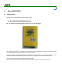
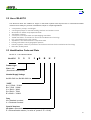
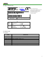

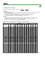


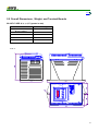

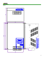
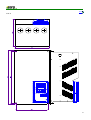
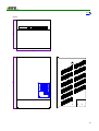
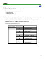


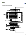

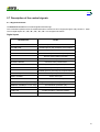
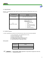

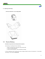


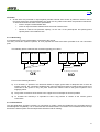


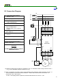
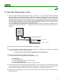
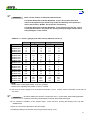

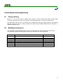
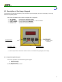
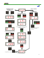
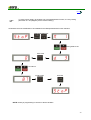

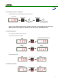
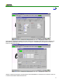
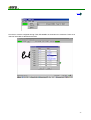
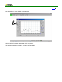
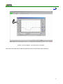
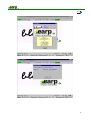

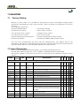

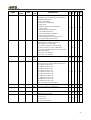


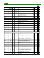
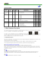
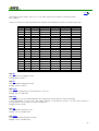


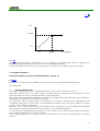
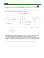

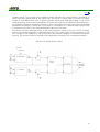
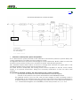
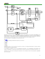

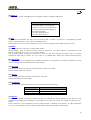


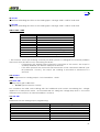

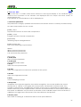

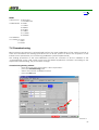


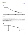

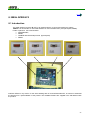


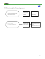
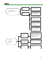
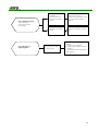
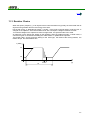
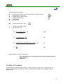

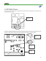


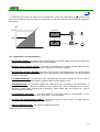


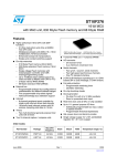

![[输入书名]](http://vs1.manualzilla.com/store/data/005783394_1-fc20c72617a19a0d7587a472ef1576a7-150x150.png)