1
US006550991B2
(12) United States Patent
(10) Patent N0.2
Michel et al.
(54)
(75)
(45) Date of Patent:
PAPER TRAY ADJUSTMENT PAGE
Inventors:
Apr. 22, 2003
5,379,101 A
1/1995 Takahashi et a1. ........ .. 355/309
5,391,009 A
2/1995
Stodder .................... .. 400/605
Paul Michel, Redwood City, CA (US);
5,532,847 A
7/1996
Maruyama ~ ~ ~ ~ ~ ~
Bradley Pirman paci?ca CA (Us)
5,775,684 A
7/1998 Jackson et a1. .......... .. 271/9.07
’
'
US 6,550,991 B2
.
’
-
5,813,771 A
-
6,118,950 A
(73)
Asslgnee' lclgiftrcoxlasjgr Imagmg’ Inc" Foster
(*)
Notice:
~ ~ ~ -- 358/498
12/1998 Ur et a1.
*
9/2000
Wibbels et a1. ............. .. 399/16
6,367,996 B1 * 4/2002 Edwards ................... .. 400/279
FOREIGN PATENT DOCUMENTS
Subject to any disclaimer, the term of this
patent
U~S'(:~ is extended7 or adjusted under 35
A2
g;
JP
08088713
(21) Appl. No.: 09/814,455
(22) Filed:
1213;
~~~~~~~~~~~~~~~~~~~~~
~ ~ ~ ~ ~ ~ ~ ~ ~ ~ ~ ~ ~ ~ ~ ~ ~ ~ ~ ~~
~ ~ ~~
4/1996
OTHER PUBLICATIONS
Mar. 22, 2001
HP Makes an Even Better Impression; BYTE, vol. 23, No.
(65)
PriOr Publication Data
Us 2OO2/0136579 A1 Sep 26’ 2002
2, p_ 129, Feb 1998_
Lasting Impression; PC User, No. 211, p. 71, May 19—Jun.
1, 1993.
(51)
(52)
Int. Cl.7 ............................................... .. B41J 11/44
U.S. Cl. ......................... .. 400/70; 399/16; 400/582;
Lasers 0n Stun; PC User, May 20—Jun_ 2, 1992
Automatic Duplex Copier; IBM Technical Disclosure Bul
(58)
Field of Search ............................ .. 400/70, 76, 61,
400/5833
400/578, 582, 279, 583.3; 399/16
letin, vol. 22, No. 4, p. 1379—1381.
* cited by examiner
Primary Examiner—Charles H. Nolan, Jr.
(56)
References Cited
’
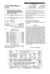
(57)
ABSTRACT
U.S. PATENT DOCUMENTS
_
Atray alignment calibration page and method and apparatus
I’:
using the page are provided. The page has graduated scales
g/
’
ichnelderlet a1‘ """" "
/
4,831,420 A
5 046 714 A
*
app et a ' """" "
2/1992 Coy et al. ..
5,120,040
6/1992
5,277,418 A
along horizontal and vertical edges, such that the scale
271/162
5,091,654 A *
A
/
5/1989 Walsh et a1. .............. .. 271/226
9/1991 Hwang
Worley
. ... ... ..
250/559.29
..
...... ..
values are enterable into an interface to align an image to be
Pnmed centered on a target Page
271/9
1/1994 Jones et a1. ............... .. 271/164
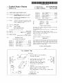
1 Claim, 3 Drawing Sheets
/—100
Tray Alignment Page
Directions:
109
1.
103
22/
it A
—
3%lg [ll/171
706
-
Fold the sheet in half horizontally.
Then open the sheet.
105
2. Fold the sheet in half vertically.
3. Then
each
Determine
open
scale.where
the
Write
sheet
theeachagain.
folds
number
crossin
Ol
772
C
35
108
lg
the box next to each scale.
Y scale
4.
Optional:
(only for printers having scaling errors)
Measure length of X and Y scales
\102
’
X scale
1012 114\l:| mm
Write measurements in the box next to each scale.
113
Bl_—_l/
:10? /104
0 51015 20 2530 354045 50
0
U S Patent
Apr. 22, 2003
US 6,550,991 B2
203
2T TI
\\L__2
UM
4
,,
_S
/0D_.\ \
202 —\
{mi
7V
__
a\
M
__
_
__
2
4
__
/_
__
2
_
___
_
,,
u
_n
A,
x
m
0
v.
_
/
FIG. 2
__
f_
__
0
__
_
___
/
/201
U.S. Patent
Apr. 22, 2003
Sheet 3 of3
US 6,550,991 B2
Paper Tray Alignment
300—\\
1.
[2|
Select Tray
2Q
311\\
Med‘“ Size
Letter
Last alignment: 1/1/90
2. Print alignment page
321\\ \E] Print Duplex
3.
A
B
Print
/
/322
3_3Q
Side 2
C
A
25 25 25
331%4’
///312
8:00:00 AM \\
\313
a)
Enter alignment values
Side 1
ET
B
C
25 25 25
//
§\\
4. Apply alignment values \332
Apply
///_333
Deiwlis
{3Q
Check Alignment /
/
3411
D
301/
one
FIG. 3
//—34Z
US 6,550,991 B2
1
2
PAPER TRAY ADJUSTMENT PAGE
using an alignment dialog box. The page has graduated
scales With values running along the horiZontal and vertical
BACKGROUND OF THE INVENTION
vertically to locate the center of the page. The end user also
edges. An end user folds the page in half horiZontally and
obtains other values, such as scaling factors, from the page.
1. Technical Field
Such values are enterable as correction values into the
The invention relates to paper alignment for printing
devices. More particularly, the invention relates to methods
and apparatus for performing paper tray alignment using an
alignment calibration page to determine and apply alignment
alignment dialog to align an image to be printed on a target
page so that printing occurs centered on the page. A set of
input image Cartesian coordinates is mapped to output
device Cartesian coordinates, taking into account scaling,
calibration values.
2. Description of the Prior Art
When a neW printer is con?gured, many features and
pieces of equipment on the printer need to be set up and
adjusted. Paper trays are no exception. For example, a
rotational, and translation factors. The invention handles
duplex printing, as Well.
BRIEF DESCRIPTION OF THE DRAWINGS
technician could spend several minutes skeWing and shifting
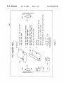
FIG. 1 is a schematic diagram shoWing a tray alignment
calibration page, Whereby alignment values can be obtained
from scales according to the invention; and
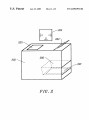
FIG. 2 is a block diagram of an apparatus for performing
tray alignment for at least one tray associated With a media
the paper trays of a printer to ensure accurate registration,
Which is the precise positioning of printed elements. Ensur
ing accurate registration is important especially When print
ing duplex pages, i.e. both sides of pages.
The locations of elements to be printed on a page are
siZe and associated With an output device to correct for
typically described in Cartesian coordinates. When printing
outputting inadequacies in the output device system accord
ing to the invention; and
such elements on a page, the elements may end up With
different coordinates than intended for the actual printed
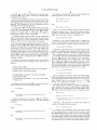
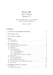
FIG. 3 is a screen print of an example of a tray alignment
page, and sometimes such elements are printed smaller or 25 dialog box for duplex printing according to the invention.
larger than expected. Such problems arise, for example,
When a medium (such as a page) feeding mechanism or
DETAILED DESCRIPTION OF THE
INVENTION
draWing device is not precisely calibrated, or When the
medium is stretched. Another problem is that sometimes
impressions are skeWed. SkeWed impressions may happen,
When a neW printer is con?gured, many features and
pieces of equipment of the printer need to be set up and
adjusted. Paper trays are no exception. For example, a
for instance, When paper trays, paper feeding mechanisms,
and draWing devices are not parallel. Yet, another problem
is that positions of printed elements are sometimes shifted,
for example, toWards the left, right, top, and/or bottom of a
technician could spend several minutes skeWing and shifting
the paper trays of a printer to ensure accurate registration
When printing duplex pages, Where registration means the
page.
35 alignment of a page in a paper tray. The discussed invention
Corrections to shifted elements are taught in Splash M
shifts and rotates an image to be printed on a page to correct
Series, User’s Manual Version 1.0, Sep. 22, 1998. A Splash
M Series Con?guration disk supports tWo page positioning
for the paper tray’s physical inadequacies. The tray align
ment technique discussed herein Works seamlessly With
con?guration parameters in a DP.INI ?le: sshift and fshift.
Workstations, LCD panels, and other applications.
These parameters alloW adjusting the position of an image
A tray alignment calibration page and method and appa
ratus using the page are provided. The page is printable
With respect to the center of the page. The image can be
repositioned in all four directions, up, doWn, right, and left.
sshift adjusts the center of the page along an S axis (sloW
scan axis) and fshift adjusts the center of the page along an
F axis (fast scan axis). The orientation of each of the S and
F axes is dependent on the direction the paper is being pulled
using an alignment dialog box. The page has graduated
scales With values running along the horiZontal and vertical
45
edges. An end user folds the page in half horiZontally and
vertically to locate the center of the page. The end user also
through the printer. The Splash technique is limited in
obtains other values, such as scaling factors, from the page.
correcting problems in shifting.
Such values are enterable as correction values into the
alignment dialog to align an image to be printed on a target
It Would be advantageous to provide methods and appa
page so that printing occurs centered on the page. A set of
ratus to shift, rotate, and scale images to be printed on a
input image Cartesian coordinates is mapped to output
device Cartesian coordinates, taking into account scaling,
page, thereby correcting for a paper tray’s physical inad
equacies.
It Would be advantageous to provide methods and appa
ratus for paper tray adjustments that Work With other
devices, such as, for example, Workstations and LCD panels,
and With other applications.
It Would be advantageous to provide methods and appa
ratus to calculate parameters for plane rotation and transla
tion by using a test pattern, and Whereby the use of any
instrument for measuring is not required.
It Would be advantageous to provide methods and appa
ratus to calculate a scaling factor parameter, and Whereby
only a ruler is needed.
SUMMARY OF THE INVENTION
A tray alignment calibration page and method and appa
ratus using the page are provided. The page is printable
55
rotational, and translation factors. The invention handles
duplex printing, as Well.
It should be appreciated that the discussed invention
herein is not limited to printing devices, but relates to any
outputting device involving outputting an image.
To print elements on a page, locations of such elements
are usually supplied using Cartesian coordinates. For vari
ous reasons, these elements may end up at different coordi
nates on the actual printed page. The invention discussed
herein measures the disparities in the coordinates and com
pensating for such differences.
65
The preferred embodiment of the invention refers to the
plane of user-requested coordinates as a user plane, and the
plane of printer-delivered coordinates as a device plane. The
user plane represents a theoretical page as seen by, for
US 6,550,991 B2
4
3
example, a graphic designer; While the device plane repre
When tWo planes have the same origin, equations for
change of coordinates by plane scaling are (CRC, page 265):
sents an actual sheet as delivered by a printing device.
The preferred embodiment of the invention describes hoW
x’ax Where a==0 is the horizontal scaling factor.
to measure disparities and to compensate for differences
betWeen user and device planes. As an example of measur
y’=by Where b==0 is the vertical scaling factor.
ing such disparities and compensating for such differences
When a=b, scaling is proportional; When a=b=1, there is no
betWeen the user and device planes, the preferred embodi
ment of the invention uses scaling, rotational, and translation
factors. The discussed invention interprets the disparities by
measuring scaling, rotational, and translation parameters,
and, thereby compensates for the differences by applying the
measured parameters to scaling, rotational, and translation
need for compensation for plane scaling.
10
When tWo planes have the same origin, and the positive
x‘ axis results from a counterclockwise rotation of the
positive x axis by an angle 6, equations for change of
coordinates by a rotation are (CRC, page 253):
standard corrective functions or transforms.
Plane scaling can be used, for example When printed
15
elements are smaller or larger than expected. This may
happen, for instance, When the medium feeding mechanism
or the draWing device is not precisely calibrated, or When the
medium is stretched. Such disparities can be corrected by a
When 6=0, there is no need for compensation for plane
rotation.
transform using plane scaling.
When tWo planes have axes Where x is parallel to x‘ and
y is parallel to y‘, and the origin of the second plane
Plane rotation can be used, for example, When impres
sions are skeWed. This may happen, for instance, When
paper trays, paper feeding mechanisms, or draWing devices
are not parallel. Skew can be corrected by a transform using
plane rotation.
coincides With the point (x0, yo) of the ?rst plane, equations
for change of coordinates by plane translation are (CRC,
25
page 253):
Plane translation can be used, for example, When posi
tions of printed elements are shifted toWards the left or the
right of a page, or toWards the top or bottom of the page.
Shifts in any possible combination of directions can be
corrected by a transform using plane translation.
When xO=yO=x‘0=y‘O, there is no need for compensation for
One targeted use for the preferred embodiment of the
plane translation.
invention is electronically adjusting paper trays by ?ltering
the siZe, angle, and location of page elements to ultimately
locate such elements at an intended position by, for example,
a designer, on the printed page. This technique is useful
These transforms can easily be combined into simple
35
linear equations.
The preferred embodiment of the invention comprises
determining and applying the parameters discussed above in
especially for tWo-sided (duplex) printing. By adjusting
independently the source paper tray and the duplex paper
a speci?c sequence of operations or transforms. The opera
tray (or duplex mechanism), images on both sides appear
tions are called at the beginning of printing a neW page to
properly aligned.
position images on the page Where a designer Wants them.
As a practical example, the PostScript language offers the
folloWing operators, presented here in the order that they
must be applied:
The preferred embodiment of the invention provides the
folloWing procedure for using a test pattern to measure
disparities and to compensate for the differences as dis
cussed above:
45
txty translate;
Printing a test pattern on one side of a page;
6 rotate; and
Measuring the test pattern;
Calculating parameters for corrections, such as, for
sxsy scale.
example, scaling factors, rotation angle, and translation
The preferred embodiment of the invention comprises a
tray alignment page, equally referred to as test pattern, and
values, and using the calculated parameters in compen
sation functions previously installed in the printing
system. Such compensation functions transform
incoming coordinates from a user plane into coordi
nates for a device plane; and
Optionally, printing a veri?cation page to con?rm accu
using the tray alignment page for gathering data to deter
mine scaling, rotational, and translation factors for perform
55
on a page.
racy of the corrective adjustment.
It should be appreciated that the phrases test pattern and
tray alignment calibration page are used interchangeably
The Tray Alignment Page
The preferred tray alignment page is described beloW and
herein.
The preferred embodiment of the invention uses standard
With reference to FIG. 1. FIG. 1 is a schematic diagram
shoWing the preferred tray alignment calibration page,
mathematical equations for coordinate systems substitutions
Whereby alignment values can be obtained from scales,
according to the invention.
or transforms. Such equations are available in many geom
etry books. One such reference is “CRC Standard Math
ematical Tables and Formulae (30”1 edition)” 1996 CRC
ing the corrective transformations or alignments of elements
65
It should be appreciated that When using tray alignment
Press. The coordinate system substitution equations used in
page 100, no measurement instrument is needed for calcu
the preferred embodiment are described below.
lating parameters for plane rotation and translation.
US 6,550,991 B2
6
5
It should also be appreciated that When using tray align
The preferred embodiment of the invention calculates the
folloWing factors in the order shoWn beloW:
ment page 100, only a ruler is needed for calculating the
scaling factor parameters.
Plane scaling factors (sxsy);
The preferred embodiment of the invention has both user
and device planes With origins in the loWer left corner of the
tray alignment page. X increases to the right and Y increases
upWards. The dimensions of the tray alignment page are
Plane rotation angle (6);
and
PageWidth Wide by PageHeight high.
A scaling mark 101 is draWn parallel to horiZontal edges
of the page. The scaling mark 101 has length XscaleLength,
Written in boX Xscale 114. A scaling mark 102 is draWn
parallel to vertical edges of the page; its length is
YscaleLength, Written in boX Yscale 115.
It should be appreciated that When a printer consistently
delivers proportional scaling, only one scale measurement is
required, and When a printer consistently delivers scaling
Plane translation values (txty)
10
That is, an end user evaluates scaling factors ?rst. If the
horiZontal scaling mark is expected to measure Xscale
Length but actually measures XscaleLength‘ on the printed
page, then the desired horiZontal scaling factor is:
15
sX=XscaleLength+XscaleLength'.
factors of 100%, then no scaling marks are required.
The tray alignment page comprises graduated bars (BarA,
BarB and BarC) (103, 104, 105, respectively) that are
20
parallel to the page edges. For attaining accuracy, these bars
Similarly, if the vertical scaling mark is eXpected to
measure YscaleLength but actually measures YscaleLength‘
on the printed page, the desired vertical scaling factor is:
sy=YscaleLength+YscaleLength'.
are located as close as practical to the page edges. The
distance betWeen each bar and its closest edge is Distance
FromEdge. The distance betWeen each graduation on a bar
is DistanceBetWeenTicks. The length of a bar is BarLength.
Point A 106 is located at the center of BarA, Point B 107 is
located at the center of BarB, and Point C 108 is located at
the center of BarC.
FolloWing are expected coordinates When every element
is precisely located Where speci?ed in the user plane, as
folloWs:
It should be appreciated that every measurement on the
printed tray alignment page integrates these scaling factors
25
above. Therefore, herein this document, scaling factors of
1.0 (no scaling required) is assumed to simplify equations.
To calculate the plane rotation angle, the end user folds
the tray alignment sheet horiZontally in half to produce a
fold line 109 passing by the vertical center of the actual
30
sheet. This horiZontal fold line 109 crosses the vertical
scales A 103 and C 105 at UserReadingA, Written in boX A
111 and UserReadingC, Written in boX C 112. Using equa
tions presented earlier, points UserReadingA and UserRead
XA=DistanceFromEdge
XB=(Page Width+2) (middle of the page, horiZontally)
ingC have the folloWing y coordinates in user plane:
35
yuserReadingA= y(USeTR6?dingA)
XC=(Page Width-DistanceFromEdge)
yusamend,”gC=Fy(UserReadingC)
yA=(PageHeight+2) (middle of the page, vertically)
yB=DistanceFromEdge
40
yC=(PageHeight+2) (middle of the page, horiZontally.
Same as yA)
Readings on horiZontal bar B 104 are converted into user
plane coordinate X by the folloWing equation:
Due to translation and rotation transforms, UserReadingA
and UserReadingC points end up at the vertical center of the
actual page (the device plane). When there is no error due to
plane rotation, then yUserReadl-ngA=yUserReadingc. In other
45
Words: the difference betWeen yUserReadl-ngA and
yUserReadl-ngc is due to plane rotation.
The angle for plane rotation is evaluated by ?guring a
right triangle from points UserReadingA, UserReadingC
x=FX(ReadingB),
and a line draWn perpendicularly from BarA 103 to BarC
105. Three values are required to solve a triangle. They are:
Where
DistanceAC=xc—xa
FX(ReadingB)=xB— (ScaleLength+2)+(ReadingB><DistanceBe
tWeenTicks).
Similarly, readings on vertical bars A 103 and C 105 are
converted into user plane coordinate y With the folloWing
De1taY=y UserReadingA “y UserReadingC
900 (right angle between the vertical graduated bars and the vir
tual line from point A to C).
55
equations:
FolloWing is the equation to evaluate the amount of
rotation to be applied betWeen planes:
y= y(Reading),
(~)=—tan’1 (DeltaY+DistanceAC)
Where
60
To calculate plane translation values, the end user folds
the tray alignment sheet vertically in half to produce a fold
line 110 passing by the vertical center of the actual sheet.
Fy(ReadingA)=yA—(ScaleLength+2)+(ReadingAxDistanceBe—
tWeenTicks),
This vertical fold line 110 crosses the horiZontal scale B 104
and
65
Fy(ReadingC)=yC— (ScaleLength+2)+(ReadingC><DistanceBe—
tWeenTicks).
at UserReadingB, Written in boX B 113. Using the equations
for plane rotation presented earlier, and the rotation angle 0
just measured, the X coordinate of UserReadingB and the y
US 6,550,991 B2
8
7
Determining alignment calibration values using the align
coordinate of UserReadingC in the rotated plane before
ment calibration page and entering such values in a tray
translation can be evaluated by:
alignment dialog; and
x UserReadingB_xUserReadingB COS 6-yB sm 9
,
_
Applying the calibration values, and printing a test page
to shoW that the alignment calibration Worked properly.
.
The folloWing should be appreciated about the preferred
embodiment of the invention. Applied alignment calibration
values replace any existing alignment calibration values.
Using equations for plane translation presented earlier,
X‘UserReadingB and y‘UserReadingC just Calculated, is
possible to evaluate hoW much translation needs to be
1O
Alignment calibration values are stored as each tray is
calibrated. When a previously calibrated page siZe is used on
generalized not to use an end user, but can be performed 15
a tray, it is not required to apply the calibration. Previously
set alignment calibration values are ignored When printing
the alignment calibration page.
The preferred embodiment of the invention stores the
folloWing data to ensure that tray alignment is performed
applied betWeen planes:
ty_y UserReadingC_yC
_
I
It should be appreciated that the discussion above can be
properly:
more broadly, such as be automated, for example.
It should also be appreciated that the discussed invention
Alignment calibration values are stored Whenever an
aligns every page that prints through the printing device.
That is, there is no need to print documents through a special
application or program. For example, a ?le printed from MS
Word can have the discussed tray alignment performed on it.
An operator doesn’t need to use any type of measuring
device to align a tray because the tray alignment sheet is
folded in half and the ruler is obsolete because the center of
the sheet is knoWn.
alignment calibration is performed;
Unique calibration values are stored for each tray-media
siZe;
Tray-media type combinations that have not been cali
brated are set to initial values; and
Data stored for each tray includes:
Top side calibration values;
25
The exact center of a page is determined through mea
surements taken on the outskirts of the sheet in the folloWing
manner. Each point on an imaginary line across the sheet is
default values.
knoWn and a remaining point on an adjacent edge of the
sheet connects to an imaginary point at a right angle, the
Tray Alignment User Interface
exact center of the sheet is knoWn.
If every image is printed to this exact center, the issue of
alignment knoWn in the art as “Top-Top” and “Top-Bottom”
duplexing is eliminated. Both versions of duplexing print to
the center of the sheet, thereby eliminating the need to
fumble With rotation of the print of origin.
The preferred embodiment provides a user interface for
performing tray alignment. Tray alignment can be per
formed using various input mechanisms, such as, but not
35
Tray Alignment Usage
The preferred embodiment of the invention provides an
apparatus for performing tray alignment to correct for out
putting inadequacies in an output device, and is described
For an example of a tray alignment dialog box, refer to
FIG. 3. FIG. 3 is a screen print of an example of a tray
example of an apparatus for performing tray alignment for
alignment dialog box for duplex printing. The tray alignment
at least one paper feeding mechanism 200 associated With a
dialog 300 separates tray alignment action for a single paper
45
An end user uses an input means 203, such as, for example,
tray into a series of four steps described beloW.
It should be appreciated that When such tray alignment
dialog box opens, previous alignment calibration values are
automatically displayed under an Enter alignment values
an LCD panel, to specify Which tray is to be aligned and
Which media-type to use. FIG. 2 shoWs one tray 200 to be
aligned and one media-type 201 Within the tray. In this
section 310.
example, through input means 203, media-type 201 and
speci?c tray 200 are speci?ed in outputting an tray align
Step 1—Select Tray
ment calibration page 204. The alignment calibration page
204 comprises markings that are used to determine align
An end user selects a paper tray to be calibrated and a
ment calibration values. The preferred tray alignment cali
bration page is discussed above. Measured calibration
parameters are entered into input means 203, Whereby
calibration values are determined and are subsequently
limited to, a Workstation, a LCD panel, and a custom print
driver interface.
As an example of an input mechanism for a Workstation
in the preferred embodiment of the invention, an end user
can open a tray alignment dialog box through a menu option,
such as, for example, a Server->Tray Alignment menu
option. Such option opens a tray alignment dialog box.
With reference to FIG. 2. FIG. 2 is a block diagram of an
media type 201 and associated With an output device 202.
Bottom side, or duplex calibration values; and
Date of last alignment calibration, Where if calibration
has not been performed, then the date and time have
55
applied to outputs.
The preferred embodiment of the invention provides the
folloWing technique for performing tray alignment on an
output device:
media siZe. Trays in pull-doWn list 311 are dependent upon
the corresponding output device. The media siZes available
312 are also dependent upon the output device.
The date and time of the last tray alignment calibration
313 is also shoWn under Select Tray 310. At initial
alignment, the date and time shoWn are default values.
Step 2—Print Alignment Page
The end user chooses to print an alignment calibration
Specifying a tray to be aligned, taking into account
page 320. If the output device is enabled for duplex printing,
Whether or not a duplexing unit is attached to the
a checkbox is available for Print Duplex 321.
If the output device is non-duplex, then the end user
device;
Printing a tray alignment calibration page. If a duplexing
unit is attached, the alignment calibration page is
optionally double-sided;
65
selects Print button 322. A single-sided tray alignment
calibration page is printed to the tray selected under Select
Tray 310.
US 6,550,991 B2
10
If the output device is duplex, then the end user sets the
duplex checkbox 321 to choose a single-sided or double
sided alignment calibration page, and then selects the Print
button 322. A single-sided or double-sided alignment cali
bration page depending on checkbox 321 status is printed
using a sheet from the tray selected under Select Tray 310.
If duplexing is installed the Align Tray for Duplex Print
ing LCD screen is shoWn. The end user selects Yes to
run tray alignment calibration for duplex, then selects
OK. Selecting No returns the end user to the Tray
5
Step 3—Enter Alignment Values
ment calibration page prints uses the tray selected at the
The end user obtains and subsequently enters calibration
alignment values that the Workstation uses to determine hoW
much the image needs to be shifted and rotated on the page
Align Tray LCD screen;
Next, the end user enters alignment values for side one of
the page under Side 1: Alignment Value A (B.& C,
respectively) LCD screens;
If an alignment calibration page for duplex is printed, then
to print properly.
FolloWing is a preferred Way for the end user to obtain
tray alignment values:
Retrieving printed tray alignment calibration page;
Carefully folding page in half vertically and in half
Alignment LCD menu;
At a Print Alignment Page option the end user selects Yes
to print the tray alignment calibration page. The align
15
the end user enters calibration values under Side 2:
Alignment Value A(B & C, respectively) LCD screens;
horiZontally, determining Where folds fall on the graphs
At an Apply Alignment Values LCD screen the end user
on page; and transcribing values taken from scales into
selects Yes to apply the alignment calibration values to
corresponding input boxes next to each scale;
the selected tray. Selecting No returns the end user to
Repeating preceding operation for duplex option, if appli
the Tray Alignment LCD menu Without applying align
cable; and
ment calibration values; and
Transferring values Written on calibration page to text
boxes A, B, and C 331 under Enter alignment values
section 330. If the Print Duplex checkbox 321 is
enabled from the Print Alignment Page section 320,
then also entering duplex values under the Side 2
section 332 of the Enter alignment values section 330.
It should be appreciated that selecting the Defaults Button
At a Check Alignment LCD screen the end user selects
25
return to the LCD Functions menu.
The Restore Defaults option restores the default tray
alignment calibration values as described beloW:
At a Select Tray LCD screen the end user selects a tray
333 causes alignment values to be set to default, or initial
number using select buttons, then selects OK; and
values. In the preferred embodiment, the default value is the
midpoint of the scale and in the example is equal to 25.
When the Defaults Button 333 is selected, a Yes/No dialog
appears asking the end user “Do you Wish set the default tray
alignment values for the current tray, or for all trays? Setting
the default values for all trays Will cause all currently stored
tray alignment calibration values to be replaced.”
Yes to print a test page to demonstrate that the align
ment calibration Was successful, and selects OK to
35
At a Restore Defaults for Tray Name LCD screen the end
user selects Yes to restore default values, and then
selects OK to return to the LCD Functions menu.
An equally preferred embodiment of the invention uses a
custom print driver interface, also referred to interchange
ably herein as a unidriver. For example, a unidriver interface
Step 4—Apply
can provide a paper source header under Which an Enable
Once all alignment calibration values have been correctly
entered under Enter Alignment Values (330, 331), the end
user selects an Apply button 341 from the Apply alignment
It should be appreciated that additional features as Well as
suggested enhancements can be added to the invention
Tray Alignment checkbox is provided.
claimed herein Without deviating from the scope and spirit
values section 340.
of the invention. TWo such examples are duplex auto
At this point, neWly entered alignment calibration values
replace any previously existing alignment calibration values.
45
Clicking the Check Alignment button 342 causes a test
guage.
page to be printed using the input calibration values.
It should be appreciated that in this example, if the Apply
button 341 is clicked, then clicking the Check Alignment
Accordingly, although the invention has been described in
detail With reference to particular preferred embodiments,
persons possessing ordinary skill in the art to Which this
button 342 causes the calibration values to be applied
invention pertains Will appreciate that various modi?cations
automatically.
The end user selects the Done button 301 to close the Tray
Alignment dialog box and end the procedure.
Another equally preferred embodiment on the invention
alloWs uses LCD panels. As an example, an end user opens
a LCD functions menu and selects a Tray Alignment menu.
55
printing a test pattern on a ?rst side of a page, the test
pattern comprising a ?rst graduated bar that is parallel
to a ?rst edge of the page, a second graduated bar that
is parallel to a second edge of the page, and a third
beloW.
The Exit Tray Alignment option exits the tray alignment
graduated bar that is parallel to a third edge of the page;
folding the page in half to produce a ?rst fold line at the
center of the ?rst edge of the page;
LCD menu and returns to an LCD functions menu.
The Align Trays option provides the folloWing:
At a Align Tray LCD screen the end user selects a tray
number using select buttons, then selects OK;
siZe, then selects OK;
and enhancements may be made Without departing from the
spirit and scope of the claims that folloW.
What is claimed is:
1. A method for performing paper tray alignment in a
printing device, the method comprising:
The Tray Alignment menu has three options: Exit Tray
Alignment, Align Trays, and Restore Defaults as described
At a Paper SiZe LCD screen the end user selects a media
sensing for tWo-sided calibration, and applying required
changes independently from a printer’s programming lan
65
reopening the page;
folding the page in half to produce a second fold line at
the center of the second and third edges of the page;
US 6,550,991 B2
11
reopening the page;
determining a ?rst location Where the ?rst fold line
crosses the ?rst graduated bar, a second location Where
the second fold line crosses the second graduated bar,
12
calculating a plane rotation angle based on the second and
third locations; and
calculating a plane translation value based on the plane
rotation angle and the ?rst and third locations.
and a third location Where the second fold line crosses 5
the third graduated bar;
*
*
*
*
*