1
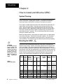
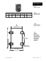
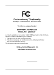
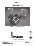
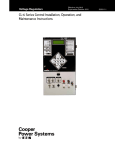
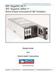
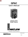
QPAC
User’s Manual
Modular SCR
Power Control
1241 Bundy Blvd., P.O. Box 5580, Winona, MN 55987-5580,
Tel: +1 (507) 454-5300, Fax: +1 (507) 452-4507 http://www.watow.com
0600-0027-0001 Rev C
July 2003
Made in the U.S.A.
$10.00
Use The Manual
Starting Out How to Use the Manual
First…
This manual will make your job easier. Reading it and applying the information is a
good way to become familiar with the QPAC. An overview:
Starting Out
Introduction, Chapter 1, Page 4.
Install/Wire
Installation and Wiring, Chapter 2, Page 6.
Operation
Operation, Chapter 3, Page 25.
Appendix
Troubleshooting, Page 28
Specifications
Warranty
Notes
NOTE:
Details of a "Note"
appear here, in the
narrow box on the
outside of each page.
A bold text "NOTE" marks a short message in the margin to alert you to an important
detail.
Safety Information
This user's manual also has boldface safety information notes to protect both you and
your equipment. Please be attentive to them. Here are explanations:
ç
CAUTION:
Details of a "Caution"
appear here, in the
narrow box on the
outside of each page.
∑
WARNING:
Details of a "Warning"
appear here, in the
narrow box on the
outside of each page.
ç
The CAUTION symbol (exclamation point) in the wide text column alerts you to a
"CAUTION," a safety or functional hazard which could affect your equipment or its
performance. A full explanation is in the narrow column on the outside of the page.
∑
The WARNING symbol (lightning bolt) in the wide text column alerts you to a "WARNING," a safety hazard which could affect you and the equipment. A full explanation is in
the narrow column on the outside of the page.
Your Feedback
We welcome comments or suggestions on this manual, please contact:
Technical Writer, Watlow Winona, 1241 Bundy Blvd, P.O. Box 5580, Winona, MN
55987-5580. Phone: 507-454-5300; Fax: 507-452-4507. The QPAC User's Manual is
copyrighted by Watlow Winona, Inc. © July 2003 with all rights reserved.
(2392)
Technical Assistance
If you encounter a problem with your Watlow controller, review your configuration
information to verify that your selections are consistent with your application: inputs,
outputs, alarms, limits, etc. If the problem persists, you can get technical assistance
from your local Watlow representative (see back cover), by e-mailing your questions to
[email protected] or by dialing +1 (507) 494-5656 between 7 a.m. and 5
p.m., Central Standard Time (CST). Ask for for an Applications Engineer. Please have
the following information available when calling:
• Complete model number
• All configuration information
• User’s Manual
• Serial Number
The model, part number, and serial numbers can be found on the label on the outside of
the case.
2
QPAC User's Manual
How to Use the Manual
How to Read the QPAC Model Number
Contents
Starting Out
The QPAC model number provides phase, supply voltage, amperage, and
control type information, in that order. For example:
Fan Cooled
480Vac Supply
3 Phase 2-Leg
30Amp (30A @ 480Vac, 3Ø)
Burst Fired, Variable Time Base
Open Heater, Shorted SCR Detector
Q32-481-030-BV2
Refer to the model number breakdown on page 31 for a complete listing.
Table of Contents
Page
Item
2
3
3
How to Use the Manual
How to Read the QPAC Model Number
Contents
4
4
5
Starting Out With The QPAC - Chapter 1
General Description
Steps To Put Your Power Control To Work
6
6
6
7
8
9, 10
11, 12
13
13
14, 15
16, 17
17
18
18
19
19
20
20
20
21
21
21
21, 22
23
24
How To Install And Wire The QPAC - Chapter 2
System Planning
Mounting The QPAC
Case Style A Mounting: QPAC-01, 30-50A
Case Style B Mounting: QPAC-01, 75-100A; QPAC-32, 30-100A
Fuse Templates
Case Style C Mounting: QPAC-01, 150-300A; QPAC-32, 150-300A;
QPAC-33, 150-300A
Case Style E Mounting: See Addendum for 400 to 1,000 Amp QPAC
Case Style F Mounting: QPAC-33, 30-100A
Power and Load Wiring, QPAC-01
Power and Load Wiring, QPAC-32
Power and Load Wiring, QPAC-33
Input Signal Wiring
CA Control Card
CD Control Card dc Input
CD Control Card Contact Closure Input
AF, AL, BF and BV Control Cards
AF, AL, BF and BV Potentiometer Input
AF, AL, BF and BV dc Input Connections
AF, AL, BF and BV Auto/Manual Input
Interlock
Soft Start
AL Control Card Current Transformer Connections
DH Option, Open Heater or Shorted SCR Detector
QPAC System Wiring Example
25
25
25
25, 26
27
How to Operate The QPAC - Chapter 3
Setup Adjustments
Phase Rotation Adjustments
Bias And Gain Adjustments
Current Limit Adjustments
28
29, 30
31
32
33
34
Appendix
Troubleshooting
Specifications
Ordering Information
Accessories
Warranty, Returns
Index
How to Use the Manual
QPAC User's Manual
3
Starting Out
Starting Out
Chapter 1
Starting Out With The QPAC,
Modular SCR Power Control
Figure 1 The QPAC-01
SCR Power Control
General Description
The QPAC Power Controls are a family of solid state controls used for electric
heating applications. A solid state power control provides output power that is
proportional to the input command signal from a temperature control. This
proportional output power helps to produce a closely controlled heater temperature, which saves energy and prolongs heater life by holding heater
elements at a nearly constant temperature.
The QPAC has a modular construction with plug-in features for flexibility. The
three modules of the QPAC are the Power Base, Transformer, and Control
4
QPAC User's Manual
Getting Started, Chapter 1
Control Cards
• Solid state contactor, AC input, CA
• Solid state contactor, DC input, CD
• Burst firing (zero cross) fixed time base, BF
• Burst firing (zero cross) variable time base, BV
• Phase angle control, AF *
• Phase angle control with current limiting, AL *
* Note: For 1Ø and 3Ø, 3 wire controls
only; not for 3Ø, 2 leg controls.
QBF
Starting Out
Starting Out
9
-528
08
U2
U1
TB
1
Plug-in transformers (50/60 Hz.)
• 120Vac
• 208/240Vac
• 380Vac
• 415Vac
• 480Vac
• 575Vac, consult factory
Figure 2 QPAC Modularity
Overview
Power Bases With Motherboards
• QPAC-01: 1Ø, 30 - 300A
• QPAC-32: 3Ø, 2 leg, 30 - 300A
• QPAC-33: 3Ø, 3 wire, 30 - 300A
Card. See Figure 2. Power Bases are avaliable in 30 to 300A ratings with
UL508 and C-UL listing and 400-1,000 amps non-agency approved in single
phase, three phase-two leg and three phase-three wire configurations. A
Transformer plugged into the Power Base allows the QPAC to operate on any
voltage from 120 to 480Vac fan. 575Vac consult factory. The plug-in Control
Card sets the QPAC’s firing mode. Control Cards are available in solid state
contactor, burst firing (zero cross), or phase angle firing with a wide variety of
options. This modular approach, using a standard Power Base with plug-in
Transformers and Control Cards, allows power control users, distributors and
OEMs to maintain minimum inventories while still providing rapid service.
The different QPACs provide the types of power control needed for different
power sources and loads. The QPAC-01 is designed for all single phase
power sources and loads. The QPAC-32 is for three phase zero cross applications such as resistance heating elements, balanced or unbalanced. The
QPAC-33 is best suited for balanced three phase, phase angle applications
requiring soft start or current limiting, or with inductive loads.
Steps To Put Your Power Control To Work
To put your QPAC to work, we suggest the following steps:
•
•
•
•
•
•
Read the User's Manual.
Plan your installation and wiring.
Mount the QPAC.
Wire your QPAC to the system.
Start the system and, if applicable, adjust the bias and gain on the QPAC.
That's all there is to it!
Getting Started, Chapter 1
QPAC User's Manual
5
Mounting
Starting Out
Installation
Chapter 2
How to Install and Wire the QPAC
System Planning
This chapter tells you how to install the QPAC. All mounting and wiring information is right here. Watlow power controls are thoroughly tested before
leaving the factory, so the QPAC is ready to install when you receive it.
This chapter is divided into three sections which describe the three steps you
need to do to install the QPAC—mounting, power wiring and control card
wiring. The first section lists the mounting information for each of the three
types of QPACs, which, depending on amperage, use one of five case styles.
The second section describes the power and load wiring of the QPACs and
semiconductor fuses, if required. The last section describes the input signal
wiring to the QPAC Control Card.
Before you begin working, read through this chapter to gain an understanding
of the entire installation. Consider the installation carefully. Plan the power,
load, and input signal wiring before mounting the QPAC. Also refer to any
noise guidelines in the temperature control documentation before proceeding.
∑
WARNING:
To avoid potential
electric shock and
other hazards, all
mounting and wiring
for the QPAC must
conform to the National Electric Code
(NEC) and other locally
applicable
codes.
Table 1 QPAC Wiring Data
Mounting the QPAC
∫
The physical size and mounting dimensions of the QPACs are different for
different current ratings. Find the "Case Style" photo on the next pages which
match your QPAC. The table and figure accompanying each case style will
give you corresponding physical dimensions and mounting footprint. The table
also indicates if the units are equipped with fans and externally-mounted fuses.
External fuse mounting templates also accompany the case style drawings. All
QPACs must be mounted vertically, power connections on top, for proper
cooling. Use the wiring data table below for wire sizes and bending radii.
Current Semi- Minimum Bending Radius
(Amps) conduc- Recomtor Fuse mended
inches (mm)
Rating Wire Size
(Amps)
30
2ea, 20
10
N/A
Lugs
Accept
# Wire
QPAC
Fuse
Model Mounting
Number
18 to 4
2ea, 40
3ea, 40
50
6
QPAC User's Manual
Q01
Onboard
Q32
External
Q33
External
Q01
Onboard
2ea, 70
Q32
External
3ea, 70
Q33
External
2ea, 30
8
1.5
(38)
18 to 4
75
100
4
2
(51)
8 to 0
All
External
100
125
1
3
(76)
8 to 0
All
External
(102)
150
200
3/0
4
4 to 3/0
All
Onboard
200
250
250 MCM
4.5
(114) 6 to 350 MCM
All
Onboard
300
400
500 MCM
8
(203) 4 to 500 MCM
All
Onboard
Install and Wire, Chapter 2
Case Style A
Starting Out
Figure 3 QPAC Case Style A
Case Style A Dimensions
Model
Amps Height (H) Width
in (mm)
in (mm)
QPAC-01 30
7
178
See
QPAC-01 50
9
229
Below
Depth
in (mm)
6.5 165
6.5 165
Fans
Fuses
None
None
Two, Onboard
Two, Onboard
Table 2 QPAC Case Style A
Overall Dimensions
Figure 4 QPAC Case Style A
Mounting Footprint
ç
5.00 (127mm)
ç
H less
H
2.00 (50.8mm)
CAUTION:
Mount the QPAC
vertically (height
dimension vertical)
for proper cooling.
Failure to do so
could result in
power control
malfunction.
Mounting Clip
Hole 0.19 (5mm)
5.80 (147mm)
6.60 (168mm)
Install and Wire, Chapter 2
QPAC User's Manual
7
Case Style B
Starting
Out
Figure 5 QPAC Case Style B
Table 3 QPAC Case Style B
Overall Dimensions
Case Style B Dimensions
Model
Amps Height (H)
Width
Depth
Fans
Fuses
Holder (max.)
in (mm) in (mm) in (mm)
in (mm)
QPAC-32 30
10.5 267 5 127 8.5 208
One Two, External*
5.69 145
QPAC-01 75
10.5 267 5 127 8.5 208
One One, External**
4.90 124
QPAC-01 100
10.5 267 5 127 8.5 208
One One, External**
4.90 124
QPAC-32 50
10.5 267 5 127 8.5 165
One Two, External*
5.69 145
QPAC-32 75
14.5 368 5 127 8.5 229
One Two, External**
4.90 124
QPAC-32 100
14.5 368 5 127 8.5 208
One Two, External**
4.90 124
* Note: See external fuse mounting drawing, Figure 7, Page 9.
**Note: See external fuse mounting drawing, Figure 8, Page 10.
Figure 6 QPAC Case Style B
Mounting Footprint
ç
1.00
(25mm)
ç
CAUTION:
Mount the QPAC
vertically (height
dimension vertical)
for proper cooling.
Failure to do so
could result in
power control
malfunction.
H
0.19
(5mm)
4.50 (114mm)
5.07 (129mm)
8
QPAC User's Manual
Install and Wire, Chapter 2
Use the next two pages as templates for mounting your fuse holder kit. Choose
the size that matches your kit and carefully punch out the template along the
perforation.
Fuse Template
Starting Out
ç
CAUTION:
Spacing for multiple
fuses must conform
to the National
Electric Code (NEC)
and any other local
electrical codes.
5.69
(145mm)
5.07
(129mm)
3.63
(92mm)
A
0.44
(11mm
B
0.22
(6mm)
0.63
(16mm)
Drill & tap
hole "B"
for #10
fasteners
Stud Size 5/16"
Figure 7 Fuse Holder Kit
Mounting Template
for:
QPAC-32, 30 & 50A
(2 Fuse Kits)
QPAC-33, 30 & 50A
(3 Fuse Kits)
Fuse Holder
(side view)
B
Install and Wire, Chapter 2
A
QPAC User's Manual
9
Fuse Template
Starting Out
Use this page as a template for mounting your fuse holder kit. Choose the size
that matches your kit and carefully punch out the template along the perforation.
4.90
(124mm)
ç
CAUTION:
4.28
Spacing for multiple
(109mm)
fuses must conform
to the National
Electric Code (NEC)
and any other local
2.84
electrical codes.
(72mm)
A
0.44
(11mm
B
0.22
(6mm)
0.63
(16mm)
Figure 8 Fuse Holder Kit
Mounting Template
for:
QPAC-01, 75 & 100A
(1 Fuse Kit)
QPAC-32, 75 & 100A
(2 Fuse Kits)
QPAC-33, 75 & 100A
(3 Fuse Kits)
Drill & tap
hole "B"
for #10
fasteners
Stud Size 5/16"
Fuse Holder
(side view)
B
10
QPAC User's Manual
A
Install and Wire, Chapter 2
Case Style C
Starting Out
Figure 9 QPAC Case Style C
Case Style C Dimensions
Model
Amps Height
Width
Depth
Fans Fuses
in (mm)
in (mm)
in
(mm)
QPAC-01 150
13
330
6.9 175
10.25 260 One
On Heat Sink
QPAC-01 200
13
330
6.9 175
10.25 260 One
On Heat Sink
QPAC-01 300
13
330
6.9 175
10.25 260 One
On Heat Sink
QPAC-32 150
13
330 14.0 348
10.25 260 Two
On Heat Sink
QPAC-32 200
13
330 14.0 348
10.25 260 Two
On Heat Sink
QPAC-32 300
13
330 14.0 348
10.25 260 Two
On Heat Sink
QPAC-33 150
13
330 21.0 533
10.25 260 Three On Heat Sink
QPAC-33 200
13
330 21.0 533
10.25 260 Three On Heat Sink
QPAC-33 300
13
330 21.0 533
10.25 260 Three On Heat Sink
Note: On 575 V~(ac) applications, the fuses are mounted external to the QPAC.
ç
∫
7.00 (178mm)
3.50 (89mm)
3.63
(92mm)
Table 4 QPAC Case Style C
Overall Dimensions
ç
CAUTION:
Mount the QPAC
vertically (height
dimension vertical)
for proper cooling.
Failure to do so
could result in
power control
malfunction.
U
P
MOUNT
13.00
(330mm)
11.75
(299mm)
∫
WARNING:
Style C heatsinks
are electrically HOT.
FAN
0.38 (10mm)
2 PL
Install and Wire, Chapter 2
Figure 10 QPAC Case Style C,
QPAC-01, 150, 200,
300A Single Phase
Mounting Footprint
QPAC User's Manual
11
Case Style C
Starting Out
∫
Figure 11 QPAC Case
Style C, Q32,
150, 200, 300A,
Three Phase-2 Leg
Mounting Footprint
ç
14.00 (356mm)
3.50
(89mm)
7.00 (178mm)
0.63 (16mm)
U
P
MOUNT
ç
11.75
(298mm)
CAUTION:
Mount the QPAC
vertically (height
dimension vertical)
for proper cooling.
Failure to do so
could result in
power control
malfunction.
13.00
(33mm)
FAN
FAN
0.375 (10mm)
4 PL
∫
∫
WARNING:
Style C heatsinks
are electrically HOT.
7.00
(178mm)
ç
21.00 (533mm)
7.00
(178mm)
3.63
(92mm)
U
P
MOUNT
Figure 12 QPAC Case
Style C, Q33,
150, 200, 300A,
Three Phase-3 Wire
Mounting Footprint
0.63 (16mm)
11.75
(299mm)
13.00
(33mm)
FAN
FAN
FAN
.375 (10mm)
6 PL
12
QPAC User's Manual
Install and Wire, Chapter 2
Case Style F
Starting Out
NOTE:
See separate
Addendum page
for Case Style E.
Figure 13 QPAC Case Style F
Case Style F Dimensions
Model
Amps Height
Width
Depth
Fans
Fuses
Holder (max) Table 5 in (mm) in (mm) in (mm)
in
(mm) QPAC Case Style F
QPAC-33
30 12.5 318 10.2 259 8.5 229 Two Three, External*
5.69
145 Overall Dimensions
QPAC-33
50 12.5 318 10.2 259 8.5 229 Two Three, External*
5.69
145
QPAC-33
75 12.5 318 10.2 259 8.5 229 Two Three, External** 4.90
124
QPAC-33 100 12.5 318 10.2 259 8.5 229 Two Three, External** 4.90
124
*Note: See external fuse mounting drawing, Figure 7, Page 9.
** Note: See external fuse mounting drawing, Figure 8, Page 10.
ç
CAUTION:
Mount the QPAC
vertically (height
dimension vertical)
for proper cooling.
Failure to do so
could result in
power control
malfunction.
ç
10.25 (260mm)
0.22 (5.6mm)
9.82 (249mm)
1.00 (25.4mm)
0.19
(4.8mm)
4 PL
U
P
MOUNT
11.00
(279mm)
9.00
(229mm)
FAN
Install and Wire, Chapter 2
Figure 14 QPAC Case Style F
30, 50, 75, 100A
Mounting Footprint
12.50
(318mm)
FAN
QPAC User's Manual
13
Wire QPAC-01
Starting Out
ç
CAUTION:
Check terminals for tightness before applying power and then recheck terminals
after one day of operation. Loose connections can damage the SCR.
∫
WARNING:
To avoid potential
electric shock and
other hazards, all
mounting and wiring
for the QPAC must
conform to the
National Electric
Code (NEC) and
other locally applicable codes.
∫
QPAC-01 Power and Load Wiring
QPAC-01
①
Circuit
Breakers
or
Disconnects
Contactors
If Required
Heater
Load
②
Onboard,
factory
installed
semiconductor
fuses
Figure 15 QPAC-01 Wiring
for 30A Units
30A
L1
L2
T1
T2
① NOTE:
On 120Vac or
277Vac, L2 is neutral
and cannot be
broken.
② NOTE:
A contactor is
required if a high
limit control is used.
QPAC-01
①
Circuit
Breakers
or
Disconnects
Figure 16 QPAC-01 Wiring
for 50A Units
14
QPAC User's Manual
Contactors
If Required
50A
Heater
Load
②
Onboard,
factory
installed
semiconductor
fuses
L1
L2
T1
T2
How to Install and Wire the QPAC, Chapter 2
Wire QPAC-01
Starting Out
ç
CAUTION:
Check terminals for tightness before applying power and then recheck terminals
after one day of operation. Loose connections can damage the SCR.
QPAC-01
①
Circuit
Breakers
or
Disconnects
Figure 17 QPAC-01 Wiring
for 75-100A Units
75-100A
②
Contactors
If Required
Heater
Load
Factory supplied,
customer installed
external semiconductor fuse
➂
Fan 120VAC/20W
L1
L2
T1
T2
L1
L2
① NOTE:
On 120Vac or
277Vac, L2 is neutral
and cannot be
broken
② NOTE:
A contactor is
required if a high
limit control is used.
➂ NOTE:
QPAC-01
①
Circuit
Breakers
or
Disconnects
A separate disconnect is required for
the fan(s) if used.
150 - 1000A
➃ NOTE
② Contactors
➃
If Required
1 Amp Fuse
Heater
Load
➂
Use 14 - 16 gauge
wire for control
power only
Fan 120VAC/20W
Onboard,
factory
installed
semiconductor
fuses
How to Install and Wire the QPAC, Chapter 2
L1
L2
T1
L1
L2
Figure 18 QPAC-01 Wiring
for 150 - 1000A Units
QPAC User's Manual
15
Wire QPAC-32
Starting Out
ç
CAUTION:
Check terminals for tightness before applying power and then recheck terminals
after one day of operation. Loose connections can damage the SCR.
QPAC-32 Power and Load Wiring
Factory supplied, customer installed
external semiconductor fuse
L3
Figure 19 QPAC-32 Wiring
for 30 - 50A Units
Circuit
Breakers
or L2
Disconnects
L1
QPAC-32
30 To 50A
Contactors
If Required
①
Heater Load
Factory supplied,
customer installed
external semiconductor fuse
Fan 120VAC/20W
L1
L2
L3
T1
T2
T3
① NOTE:
②
A contactor is
required if a high
limit control is used.
L1
L2
② NOTE:
A separate disconnect is required for
the fan(s) if used.
QPAC-32
L3
Circuit
Breakers
or L2
Disconnects
L1
① Contactors
If Required
75 to 100A
Factory supplied,
customer installed
external semiconductor fuse
Factory supplied, customer
installed external
semiconductor fuse
Fan 120VAC/20W
Top end of heatsink
L1
L2
L3
②
Figure 20 QPAC-32 Wiring
for 75-100A Units
Bottom end
of heatsink
T1
T2
L1
L2
T3
Heater Load
16
QPAC User's Manual
How to Install and Wire the QPAC, Chapter 2
ç
CAUTION:
Check terminals for tightness before applying power and then recheck terminals
after one day of operation. Loose connections can damage the SCR.
QPAC-32
150 - 1000A
Figure 21 QPAC-32 Wiring
for 150 - 1000A Units
L3
Circuit
Breakers
L2
or
Disconnects
Wire QPAC-33
Starting Out
①
Heater
Load
➂
Contactors
If Required
1 amp
fuse
L1
Fan 120VAC/20W
L1
L2
T1
Onboard
factory installed semiconductor
fuses
L3
L1
L2
T3
②
① NOTE
A contactor is
required if a high
limit control is used.
② NOTE:
A separate disconnect is required for
the fan(s) if used.
➂ NOTE:
Use 14 - 16 gauge
wire for control
power only.
QPAC-33 Power and Load Wiring
QPAC-33 All Models
L1
Circuit
Breakers
L2
or
Disconnects
①
Heater
Load
Contactors
If Required
L3
Fan 120VAC/20W
L1
T1
L2
T2
3 factory supplied
semiconductor fuses
30-100A customer installed
150-300A factory installed
L3
T3
Figure 22 QPAC-33 Wiring
All Units
L1
L2
②
Hybrid
How to Install and Wire the QPAC, Chapter 2
QPAC User's Manual
17
Input Wiring
Starting Out
Input Signal Wiring
When wiring the input signal do not run any signal wires alongside or in the
same conduit with the A.C. power or load wires. Signal input should be
provided by shielded, two conductor wire. Shield should be grounded at the
temperature control end only. Wrap the power control end with electrical tape.
The following figures show the wiring configuration for the input signal to the
QPAC Control Cards.
CA Control Card
ç
CAUTION:
Built-in noise
reduction circuitry
on the CA card
requires an external
load resistor (1000Ω,
25watt, typical)
across the input
when operating from
a triac source, to
prevent false
triggering. Failure
to apply this resistor
could result in
damage to product
and equipment, or
injury to personnel.
Figure 23 CA Card Wiring
SS Contactor,
120VAC Input
18
QPAC User's Manual
The 120Vac input (24 volts input optional) signal lines for the CA (ac Input,
Solid State Contactor) Control Card are connected to Pins 1 and 3 of the input
signal connector. A 120Vac input signal turns the power control ON. The turn
OFF voltage for the power control is 0Vac.
ç
2.50in. (63.5mm.)
1
120VAC
Input
08-5285
2
3
1.50in.
(38.1mm.)
Motherboard Connector
How to Install and Wire the QPAC, Chapter 2
Input Wiring
Starting Out
CD Control Card DC Input
For DC input, the input signal is wired into Pin 2 (+) and Pin 3 (-) of the input
signal connector. An input signal of 3-30VDC turns the QPAC power control
ON. 0-1VDC turns the power control OFF.
2.00 (51mm)
08-5286
1
Pin 2 (+)
2 (+)
Pin 3 (-)
3 (-)
1.50
(38mm)
Figure 24 CD Control Card,
Solid State Contactor, 3-30Vdc Input
Motherboard Connector
CD Control Card Contact Closure Input
For a contact closure input to the CD Control Card, the contact is wired to pins
1 and 2 (+) of the input signal connector. A closed contactor input turns the
QPAC ON and an open contact turns the QPAC OFF. The input impedance is
10KΩ minimum.
Figure 25 CD Control Card,
Solid State
Contactor, Contact
Closure Input
2.00 (51mm)
1
08-5286
2 (+)
3 (-)
1.50
(38mm)
Motherboard Connector
How to Install and Wire the QPAC, Chapter 2
QPAC User's Manual
19
Input Wiring
Starting Out
Process Input - AF, AL, BF and BV Control Cards
The QPAC AF, AL, BF and BV Control Cards are defined as follows:
AF - Phase Angle Control
AL - Phase Angle Control with Current Limit
BF - Burst Firing (Zero Cross), Fixed Time Base
BV - Burst Firing (Zero Cross), Variable Time Base
All four of these cards can be wired for a manual potentiometer input or an input
from a temperature control. The following paragraphs give the connections for both
configurations including an Auto/Manual configuration where the input can be
switched between manual and temperature control input.
AF, AL, BF and BV Potentiometer Input
For potentiometer input, wire a 1KΩ potentiometer to the “POT”, “+” and “-” connections of the control card. The wiper of the potentiometer should be connected to the
“+” connection. The control card must be converted to a voltage input by replacing a
jumper. See Page 25.
2.75 - 3.75 (70 - 95mm)
Figure 26AF, AL, BF, BV
Potentiometer Input
1
CW-
2.19 - 2.75
(56 - 57mm)
Pot
+
1KΩ Pot
5 -
CCW+
Motherboard Connector
AF, AL, BF and BV DC Input Connections
The temperature control output to the Control Cards is wired to the “+” and “-” input
terminals of the control card. These cards will accept a 0 to 12VDC, or 0 to 25mA
input signal. They are factory calibrated for 4 to 20mA. If using a voltage or current
range other than this, see Chapter 3, Bias & Gain Adjustments. The control card
can be converted to a voltage input by removing a resistor or replacing a jumper.
See Page 25.
2.75 - 3.75 (70 - 95mm)
Figure 27 AF, AL,
BF and BV
DC Input
1
DC Input
+
-
2.19 - 2.75
(56 - 57mm)
Pot
+
5 -
Motherboard Connector
20
QPAC User's Manual
How to Install and Wire the QPAC, Chapter 2
AF, AL, BF and BV Auto/Manual Input
The AF, AL, BF and BV Control Cards can be wired to make it possible to
select an input from either a temperature control or a manual input potentiometer. A switch is used to select between the input from a 1KΩ potentiometer or a
4-20mA temperature control. The control card must be converted to voltage
input by removing the appropriate resistor or replacing a jumper. See Page 25.
A 250Ω resistor must be placed in parallel with the temperature control input,
so that the temperature control signal will be a 1-5 volt input.
Input Wiring
Starting Out
2.75 - 3.75 (70 - 95mm)
DC Input
CW
1KΩ Pot
250Ω
1
2.19 - 2.75
(56 - 57mm)
Pot
+
CCW
Figure 28 AF, AL,
BF and BV
Auto/Manual Input
5 -
Motherboard Connector
Interlock
Opening the interlock connection between Pins 1 and 2 of the input signal
connector will interrupt the input signal to the control card. Do not use the interlock
for limit or safety functions. Do not open the AF or AL Control Card interlock,
terminals 1 & 2, when "soft start" is desirable.
Soft Start
Some heater elements change resistance with temperature. Certain types
such as tungsten, change resistance very fast (tungsten increases resistance
over 16 times from cold to hot). By slowly increasing the voltage to the heater,
the heater element is warmed to full resistance by the time full voltage is
applied, thus reducing excessive surge currents. Soft start time on the QPAC
is about 6 seconds from power-up. If the QPAC is forced into emergency shut
down (ESD) the QPAC will re-start soft. Soft start is only available on phase
angle models.
AL Control Card Current Transformer Connections
The AL Control Card is wired to a transformer from the load line of the QPAC.
The transformer is wired into Pins 1 and 2 of Connector TB3 of the AL card.
The following table and figures show the transformer connections for different
load configurations and currents.
Current Transformer
(Part Number)
16-0246*
16-0246*
16-0246*
16-0246*
16-0008
16-0044
16-0072
16-0008
16-0045
16-0073
Not Used
Note:
20A
30A
40A
50A
**75A
100A
125A
150A
200A
300A
5A
:
:
:
:
:
:
:
:
:
:
:
20mA
30mA
40mA
50mA
5A
5A
5A
5A
5A
5A
20mA
Description
Interstage
Transformer
Current Transformer
Current Transformer
Current Transformer
Current Transformer
Current Transformer
Current Transformer
Current Transformer
Current Transformer
Current Transformer
Current Transformer
Interstage Transformer
Not Used
Not Used
Not Used
Not Used
16-0176
16-0176
16-0176
16-0176
16-0176
16-0176
16-0176
Table 6 AL Control Card,
Current Transformer
Selection
*With Wire Leads.
**Use two wire passes through current transformer #16-0008 for 75A applications.
How to Install and Wire the QPAC, Chapter 2
QPAC User's Manual
21
Input Wiring
Starting Out
AL Control Card Current Transformers, cont'd.
T1
CT
Figure 29 Current Transformer
(C.T.) Connections,
One C.T. 50 Amps Or
Less, 1Ø
20mA
TB-3
AL Card
TB-2
Load Wire
T2
CT
Load
T1
Figure 30 - Example
Current Transformer
(C.T.) Connections
One C.T., 75 Amps
and Above, 1Ø
Bk
Red
20mA
Wh
Bk
TB-3
Red
5A
1
Bk
16-0176
Transformer
5A:20mA
CT
T2
AL Card
TB-2
5
①
T1
Figure 31 - Example
Current Transformer
Connections,
Two C.T.'s for Two
LegSensing, 75
Amps and Above
Wh
Bk
22
QPAC User's Manual
20mA
5A
Bk
① NOTE:
Both load leads
must pass through
the C.T.'s in the
same direction.
Red
Bk
Bk
Wh
T3
CT
T2
Red
TB-3
AL Card
TB-2
16-0176
Transformer
①
How to Install and Wire the QPAC, Chapter 2
Input Wiring
Starting Out
Single and Three Phase DH Option
Open Heater or Shorted SCR Detector
120 VAC
N.C.
Momentary
Reset
Switch
To Alarm
or Contactor
Figure 32
Single and Three
Phase Wiring
Customer Supplied Relay
(Philips ECG PIY 1055 or equivalent)
Open heater
when lit
1
Shorted SCR
when lit
DH
08-5405
2
Interstage transformer
16-0176 for 75 amps
and above
P1
J2
U4
2.20"
(56 mm)
① NOTE:
Single Phase
T1
CT
Load Wire
J3
Motherboard
Connector
Interstage
transformers (160176) required for
units 75 amps and
above.
①
Three Phase
Interstage transformer
16-0176 for 75 amps
and above
1.20"
(30 mm)
T1
①
Load Wires
T3
2.70"
(69 mm)
J3
Three Phase
(Without
Interstage
Transformer)
Operation
J3
T1
Load Wires
T3
ç
CAUTION:
The shorted SCR
detector feature will
not work with the
manual control
input;
①
The DH card uses a CT to monitor the load current and also detects when a firing
pulse is sent to the SCR's. The load current must be set by the pot on the DH board
(P1). If there is load current and no pulses to turn on the SCR's, the "Shorted SCR"
LED will be lit. The opto triac (U4) closes 3 or 4 seconds later and energizes an
external alarm relay. If part of the load opens (20% or more), and there are SCR
pulses, the "Open Htr" LED is lit and 3 to 4 seconds later, the alarm relay energizes.
This board only operates with the zero cross firing cards. For three phase, the CT's
go in T1 and T3 lines.
Setup Procedure
1. With the DH card installed and the temperature control wired to the SCR
power control, set the temperature control output to "full on" (20mA for 420mA output, or 5 volts for 0 to 5 volt output).
2. Adjust P1 until the open heater light on the DH card is full on. No
intermittent cycling.
3. Slowly adjust P1 until the open heater light just turns full off. No
intermittent cycling.
If you are getting false alarms, adjustment is probably set too sensitive and
should be readjusted towards the off condition of the open heater light.
A shorted SCR will energize the shorted SCR light.
Load
Current
2 to 3 Amps
3 to 4 Amps
4 to 5 Amps
5 to 10 Amps
10 to 40 Amps
Number of Passes of Load Wire
Thru Current Transformer
5
4
3
2
1
How to Install and Wire the QPAC, Chapter 2
Table 7Load Wire Passes
Thru Current
Transformer
QPAC User's Manual
23
System Wiring
Starting Out
QPAC System Wiring Example
Figure 33 QPAC System
Wiring Example
∫
Line
Line
Neutral
Neutral
Overtemp.
Indicator
11
Fuse
5
(-)
Breakers
Contactor
10 -
93BA-1FA0-00RR
Semiconductor
Fuses
L1
9 +
Series 93
Thermocouple Input
Process Output
Reset
Switch
High
Limit
12
(+) 3
Line
Circuit
WARNING:
Follow National
Electric Code
safety practices
and other locally
applicable codes to
avoid potential
electric shock
when wiring this
unit to a power
source, and to
electrical sensors
or peripheral
devices. Failure to
do so could result
in serious injury or
death.
Fuse
Series
147
High Limit
Fuse
L1 T1 L2 T2 L3
∫
Neutral
Tungsten (Lamp)
Infrared Heater
T1
L2
T2 L3
T3
Fan
Power
+
1
5
QPAC-33
with
AF Control Card
DC Input
Overtemperature cutout. The most common failure mode of an SCR is in the
shorted state. If this happens, the temperature control can no longer control
the SCR and a run-away condition exists. An independent high limit control
must be used that will sense unsafe temperature and disengage the circuit
breaker via undervoltage trip or a mechanical contactor as shown above.
24
QPAC User's Manual
How to Install and Wire the QPAC, Chapter 2
Chapter 3
Operation
Starting Out
How to Operate the QPAC
Setup Adjustments
After the QPAC is installed and wired it may need a few minor adjustments. The
three phase power controls require that proper phase rotation exists. QPACs
that use the BF, BV, AF or AL Control Cards may need minor bias and gain
calibrations. QPACs that use the AL Phase Angle Current Limit Control Card
will need current limit calibration. Refer to the following paragraphs.
Phase Rotation Adjustment for Q32 and Q33
Three phase QPAC SCR controllers require the correct phase sequence of the
attached line voltage. To check for proper phase sequence of the QPAC-32
power control, measure the voltage from T1 to T2, T2 to T3 and T3 to T1 with
the power control turned full ON. If any of the measurements of output voltage
are not equal (within 10%), exchange any two of the power input lines (L1 and
L2) to the QPAC.
To check for proper phase sequence of the QPAC-33 power control, apply
power to the QPAC and observe the LED indicators in the upper left hand corner
of the Power Base motherboard. If the phase rotation LED is not illuminated,
exchange any two incoming power lines (L1 and L2).
Bias And Gain Adjustments for AF, AL, BF, BV
Bias and gain can be adjusted to interface with the output of most standard
temperature controls with a proportional output. Bias and gain is factory set for
an input control signal of 4-20mA but can be adjusted over a range of 0-12VDC
or 0-25mA to match the output of a specific temperature control. Input impedance for 4-20mA input is 250Ω. The input impedance can be changed to 5KΩ to
accept a voltage by performing the following procedure for each card.
Voltage Input Conversions
AF (08-5288): For 5KΩ input, move J2 jumper, located on the lower left of the
AF card next to the TB-2 connector, Terminal 5. See Figure 34.
AL (08-5411): For 5KΩ input, replace the J2 jumper to the 5V position,
located on the lower left of the AL card to the 5V position. See Figure 37.
BF (08-5289): For 5KΩ input, remove resistor R3, located on the lower left of
the QBF card next to the TB-2 connector, Terminal 5. See Figure 35.
BV (08-5342): For 5KΩ input, remove the external resistor attached to the J3
connector plug. See Figure 36.
Adjustment Procedure:
We recommended that bias and gain adjustment be performed using a dummy
load. In some applications, a dummy load may be required if the controlled load
can not be turned full ON. A dummy load can be easily made by connecting 150
watt lamps in series to match the operating voltage of the QPAC. Use the
following steps to make adjustments.
How to Operate QPAC, Chapter 3
QPAC User's Manual
25
Bias & Gain
Starting Out
1.
Connect a volt meter across the load or dummy load of the QPAC. Connect
a volt meter across, or milliamp meter in series with, the input signal from the
temperature controller. NOTE: AL card should be calibrated with a dummy
load on the QPAC
2.
Apply power to the system.
3.
Set the output signal of the temperature controller to zero or its minimum
output. The QPAC input is factory calibrated for full off at 4.2 mA. Adjust the
bias potentiometer slowly CCW (counterclockwise) until the QPAC output just
comes ON. Then turn CW (clockwise) until the output is just full OFF as
observed on the output volt meter. See the following figures for the location of
the bias and gain potentiometer on the Control Cards.
NOTE: The QBV card does not include a bias adjustment. A bias and gain
adjustment card can be added to the QBV card in the field. Order Watlow part
number 08-7210. Follow this calibration procedure when using the bias and
gain card.
4a. AF & BF: Adjust the output of the temperature controller to full ON (5VDC,
20mA, etc.). Adjust the gain potentiometer CW until the QPAC output is just
full ON. The QPAC is factory calibrated to be full on at 19.8 mA.
4b. BV & AL: Adjust the output of the temperature controller to full ON (5VDC,
20mA, etc.). Adjust the gain potentiometer CCW until the QPAC output is just
full ON. The QPAC is factory calibrated to be full on at 19.8 mA.
Figure 34 AF (Rev. H)
Control Card
5.
When adjusting the bias and gain of the current limiting (AL) control card,
ensure that the current limiting is turned OFF. With the output of the temperature control full ON, adjust the current limit potentiometer until the QPAC
output is full ON.
6.
Repeat steps 3 and 4 until the QPAC turns full ON with a full ON signal from
the temperature control, and full OFF with the minimum input signal from the
temperature control. Steps 3 and 4 may need to be repeated a few times (an
adjustment made on one of the potentiometers affects the adjustment of the
other potentiometer).
7.
Remove power, disconnect the meters, and reconnect the controlled load to
the QPAC if required.
08-5288
Gain
Pot
R39
R38
Bias
Pot
1
5
TB-2
4-20mA
5V
Gain
Pot
TB1
Bias
Pot
08-5289
Figure 35 BF (Rev. D)
Control Card
R17
1
R3
5
TB-2
26
QPAC User's Manual
TB1
How to Operate QPAC, Chapter 3
Fixed Bias
Connector
Bias & Gain
Starting Out
Gain
Pot
J3
Figure 36 BV (Rev. B)
Control Card
1
BV Fixed Bias Connector
& Gain Adjustment
5
J1
TB-1
08-5342
Bias
Pot
Gain
Pot
Current Limit Pot
(AL Card only)
08-5411
Figure 37 AL (Rev. B)
Control Card
1
CT
TB-2
2
AL Bias, Gain, & Current Limit
Adjustments
1
TB-1
5
4-20mA
5V
NOTE:
The AL Current
Limit must be
disabled (pot fully
clockwise - CW)
before bias and gain
can be adjusted.
Motherboard Connector
Current Limit Adjustments
The AL Control Card is a phase angle control with the capability to limit the
maximum current to the load. A potentiometer on the AL adjusts the current
limit setting. See Figure 37. Use the following steps to adjust the current limit
on initial setup. The purpose of the procedure is to bring the power to the load
up slowly so that the maximum current to the load is not exceeded before the
current limit is adjusted.
Note: A short overcurrent through the load may occur, as the AL Card circuitry
detects the higher current, if the input signal from the temperature control is
abruptly increased.
1. Attach a clamp-on ammeter to the load line.
2. Adjust the AL card current limit potentiometer fully counterclockwise (for
minimum current flow).
3. Turn the temperature control ON and adjust the input signal to the control
card for zero percent power.
4. Turn the power to the QPAC ON.
5. Gradually increase the input signal.
6. Adjust the current limit potentiometer clockwise until current to the load is
measureable.
7. Gradually increase the input signal to 100% power, then adjust the current
limit potentiometer to obtain the desired maximum current to the load.
How to Operate QPAC, Chapter 3
QPAC User's Manual
27
Troubleshoot
QPAC Troubleshooting
A technician can isolate a system problem by first checking if the load is good,
and the line voltage and temperature signals are present and correct. If the
above is true, then the power control may be the problem. This problem may
be with the QPAC's control card, transformer or power base. Use Table 8 to
assist with troubleshooting.
Symptom
No output
Table 8QPAC Troubleshooting Guide
Probable Cause
Fuses blown
Incorrect input wiring
Incorrect input signal
Input signal reversed
Input signal not adjusted
Wrong or missing control card
Transformer wiring
Missing load wiring
Heatsink
temperature
exceeded
187°F (86°C)
Clogged or non-operational fan
Transformer
hot
Uncontrolled
output full ON
Incorrect transformer
Bad control card, or bias and
gain out of adjustment
Bad transformer
Bad power base
Unbalanced
output
(QPAC-32
& QPAC-33)
Incorrect phase rotation
Corrective Action
Check and replace fuses
See “Input Wiring,” p. 18-23.
Check temp. control output.
See “Input Wiring,” p. 18-23.
See “Bias and Gain Adjustment"
p. 25-26.
See “Input Wiring,” p. 18-23.
Check transformer connections.
See “Power and Load Wiring,”
p. 14-17. The SCR(s) will not
function without a load.
Check fan, power, and clean if
necessary. Check for shorted
thermostat, replace fan or thermostat as necessary. #27-0005
thermostat is normally open and
closes on temperature rise.
Check product & transformer
labels.
Unplug control card, try again.
Readjust bias & gain.
Unplug transformer wire and
try again.
If full ON or half ON output
present with no control card
and no transformer, power
base is bad, replace.
See "Phase Rotation Adjust.,"
p. 25.
QPAC-33 Diagnostics
The QPAC-33 has four LEDs for diagnostic indication. During normal operation, all four LEDs will be illuminated.
• Power ON
Yellow LED is ON when power is applied to the control.
• Phase Loss
Yellow LED is ON when all three phases of line voltage
are present. LED will be OFF if one phase is low or lost.
• Phase Rotation
Yellow LED is ON when correct voltage phase exists,
even when load is not wired. LED will be OFF when two
phases are rotated, and when one phase is missing.
• Phase Lock Loop Yellow LED is ON when phase lock loop circuit is
synchronized. LED can go OFF from noisy power line or
if the phase synchronizing circuitry fails. Check power
quality, then repair or replace power base.
28
QPAC User's Manual
Appendix
QPAC Specifications—(1293)
Operation
• Modular control base with plug-in card and transformer
• Plug-in control cards
Solid state contactor, Å(ac) or Î(dc) input
Burst fire control, fixed or variable time base
Phase angle fire control
Phase angle control with soft start and current limiting
• Plug-in transformers (50/60Hz)
• 120, 208, 240, 277, 380, 415, 480, 575V~(ac) operation1
Power bases
• Single phase (Q01), 1 pair of SCRs
• Three phase (Q32), 2 leg control, 2 pair SCRs. Resistive load only, burst
firing only.
• Three phase (Q33), 3 pair hybrid SCRs/diodes. Recommended for phase
angle only with balanced load.
• 30 through 1000 amps per switched leg.
Agency Approvals
• UL 873 to 300 amps, File #E43684, formerly #E67609
• UL 508 and C-UL Listed to 300 amps, File #E73741
• No agency approvals beyond 300 amps.
Control Card Inputs
(CA) Solid state contactor, ac input
• 120V~(ac) @ 30mA minimum
• Å(ac) signal input sources (i.e., triacs or mechanical relay outputs with
noise suppression) require customer supplied resistors across the power
controller Å(ac) command signal input terminals to prevent false firing.
24V~(ac) input, 200Ω/10 watts typical;
120V~(ac) input, 1kΩ/25 watts typical;
240V~(ac) input, two 1kΩ/25 watts in series typical
(CD) Solid state contactor, dc input
• ON, 4-10VÎ(dc) @ 0.5mA; OFF, 0.5VÎ(dc)
• Built-in noise reduction network
(BF) Burst firing control fixed time base
• Process input factory set @ 4-20mA Î(dc)
• Input impedance 250Ω (clip resistor for 5kΩ voltage input), or manual
control input
• Time base 4 seconds (clip resistor for 1 sec)
(BV) Burst firing control, variable time base
• Process input factory set @ 4-20mA Î(dc)
• Input impedance 250Ω (clip resistor for 5kΩ voltage input), or manual
control input
(AF) Phase angle control
• Process input factory set @ 4-20mA Î(dc)
• Input impedance 250Ω (clip resistor for 5kΩ voltage input), or manual
control input
• Soft start approximately 6 seconds upon power-up, 1 second upon set
point change
(AL) Phase angle control with current limit
• Process input factory set @ 4-20mA Î(dc)
• Input impedance 250Ω (clip resistor for 5kΩ voltage input), or manual
control input
• Soft start approximately 6 seconds upon power-up, 1 second upon set
point change
• Current transformer included
• 120V~(ac) through 575V~(ac)1
• 1 or 3 pole only
Appendix
Specifications
QPAC User's Manual
29
Specifications
Line Voltage/Power
• 50/60 Hz Å(ac) line frequency, Q32 and Q33 calibration line frequency
dependent
• Voltage: ±10%, 120, 208, 240, 277, 380, 415, 480, 575V~(ac)1
Line Voltage Compensation
• 10%∆ in line, 2%∆ in load in the 30% to 70% power region (AF, AL and BV)
Power Dissipation (Watts)
• 1.5 watts/amps per controlled leg
Isolation
• Command signal to load 1250V~(ac) minimum
Linearity
• 2%, 30% to 70% power region (All units except CA & CD)
Off-State Leakage Current
• 20mA @ 480V~(ac)
SCR Protection
• Semiconductor fuses provided dv/dt 200V/µsec minimum
• MOV2 and RC snubber network standard
• (Q32) 3rd leg fuse kit may be used, but not required, with 3-phase, 2 leg
models
Mounting
• Heat sink fins must be mounted in vertical orientation
Operating Environment
• 32 to 122°F (0 to 50°C)
• 0 to 90% RH, non-condensing
Storage Temperature
• -40 to 185°F (-40 to 85°C)
Options
• Manual Control Kit for process input cards (1k potentiometer) #08-5362
• 240V~(ac) cooling fans in place of 120V~(ac) cooling fans
Weight
• lbs (kg)
Amps
30
50
75
100
150
200
300
1ø/Q01
6 (2.7)
6 (2.7)
10 (4.5)
10 (4.5)
15 (6.8)
15 (6.8)
15 (6.8)
Phase
3ø,2 leg/Q32
8 (3.6)
8 (3.6)
15 (6.8)
15 (6.8)
36 (16.3)
36 (16.3)
36 (16.3)
3ø,3 wire/Q33
20 (9.1)
20 (9.1)
50 (22.7)
50 (22.7)
50 (22.7)
50 (22.7)
50 (22.7)
*See addendum for 400-1000 amp models
NOTES:
1
Q33 models operating on 575 VÅ(ac) are not UL or C-UL listed.
2
MOV comes only on Q33 (3-phase, 3 leg).
3
All cooling fans rated @ 20 watts each, must be wired by customer.
4
The open heater/shorted SCR detector is for burst fire operation only.
5
Included one current transformer for 1-phase and two current transformers
for 3-phase. Models 75 amps and above require one interstage transformer.
30
QPAC User's Manual
Appendix
Model No.
Model Number Information — (1294)
To order, complete the code number
to the right with the information below:
Q
QPAC = Modular power controller; phase angle, burst,
or solid state contactor with fuse(s) and holder(s) included.
Phase
01
= Single phase
32
= 3-phase, 2 leg (optional 3rd leg fuse kit extra.)
33
= 3-phase, 3 leg
Operating and Output Voltage
12
= 120V~(ac)
20
= 208V~(ac)
24
= 240V~(ac)
27
= 277V~(ac)
38
= 380V~(ac)
41
= 415V~(ac)
48
= 480V~(ac)
57
= 575V1~(ac)
Cooling Fan Voltage3
Customer to supply wiring and hook-up.
0
= No fan; all 1-phase 30 and 50 amp models only
1
= 120V~(ac); required on all 3-phase models
2
= 240V~(ac); required on all 3-phase models
Output Current (Amps)
030 = 30 amps
050 = 50 amps
075 = 75 amps
100 = 100 amps
150 = 150 amps
200 = 200 amps
300 = 300 amps
400 = 400 amps
500 = 500 amps
600 = 600 amps
800 = 800 amps
01K = 1000 amps
Input Control Card
CA = Solid state Å(ac) input (08-5285) contactor
CD = Solid state Î(dc) input (08-5286) contactor
BF = Burst fired, fixed time base (08-5289) 4-20mA
BV = Burst fired, variable time base (08-5342) 4-20mA
AF = Phase angle fired, not available on Q32 (08-5288) 4-20mA
AL = Phase angle fired w/current limit, not available on Q32 (08-5411); 4-20mA
includes one current transformer. Add second CT for 3-phase, 3 leg.
AL models 75 amps and above require one interstage transformer.
Open Heater/Shorted SCR Detector4,5
0
= None
1
= Single phase operation
2
= Three phase operation
Appendix
QPAC User's Manual
31
Accessories
Accessories
08-5362
* 16-0246
* 16-0246
* 16-0246
* 16-0246
16-0071
16-0042
** 16-0008
16-0044
16-0072
16-0008
16-0045
16-0073
16-0069
16-0176
=
=
=
=
=
=
=
=
=
=
=
=
=
=
=
Manual Control Kit
20A : 20mA
30A : 30mA
40A : 40mA
50A : 50mA
30A : 5A
50A : 5A
75A : 5A
100A : 5A
125A : 5A
150A : 5A
200A : 5A
300A : 5A
600A : 5A
5A : 20mA
Current Transformer
Current Transformer
Current Transformer
Current Transformer
Current Transformer
Current Transformer
Current Transformer
Current Transformer
Current Transformer
Current Transformer
Current Transformer
Current Transformer
Current Transformer
Interstage Transformer
*With wire leads
** Use two wire passes through current transformer #16-0008
for 75A application.
32
QPAC User's Manual
Appendix
Warranty
Warranty
The QPAC is warranted to be free of defects in material and workmanship for
36 months after delivery to the first purchaser for use, providing that the units
have not been misapplied. Since Watlow has no control over their use, and
sometimes misuse, we cannot guarantee against failure. Watlow's obligations
hereunder, at Watlow's option, are limited to replacement, repair or refund of
purchase price, and parts which upon examination prove to be defective within
the warranty period specified. This warranty does not apply to damage resulting from transportation, alteration, misuse, or abuse.
Returns
1. Call Watlow Customer Service, (507) 454-5300, for a Return Material
Authorization (RMA) number before returning any item for repair. We need
this information:
• Ship to address
• Bill to address
• Contact name
• Phone number
• Method of return shipment
• Your P.O. number
• Detailed description of the problem
• Any special instructions
• Name and phone number of person returning the product.
2. Prior approval and an RMA number, from the Customer Service Department, is needed when returning any unused product for credit. Make sure
the RMA number is on the outside of the carton, and on all paperwork
returned. Ship on a Freight Prepaid basis.
3. After we receive your return, we will examine it and try to verify the reason
for returning it.
4. In cases of manufacturing defect, we will enter a repair order, replacement
order or issue credit for material returned.
5. To return products that are not defective, goods must be be in new condition, in the original boxes and they must be returned within 120 days of
receipt. A 20 percent restocking charge is applied for all returned stock
controls and accessories.
6. If the unit is unrepairable, it will be returned to you with a letter of explanation.
7. Watlow reserves the right to charge for no trouble found (NTF) returns.
Appendix
QPAC User's Manual
33
Index
A
AL Control Card
Auto/Manual Input, 21
Current Limit Transformer, 21-22
dc Input, 20
Potentiometer Input, 20
AF Control Card
Auto/Manual Input, 21
dc Input, 20
Potentiometer Input, 20
Appendix, 28
Auto/Manual Input, 21
B
BF Control Card
Auto/Manual Input, 21
dc Input, 20
Potentiometer Input, 20
Bias and Gain Adjustments, 25, 26
Burst Firing SCR Control, 5, 20, 29
BV Control Card
Auto/Manual Input, 21
dc Input, 20
Potentiometer Input, 20
C
CA Control Card, 18
CD Control Card
Contact Closure Input, 19
dc Input, 19
Case Style A Mounting, 7
Case Style B Mounting, 8
Case Style C Mounting, 11, 12
Case Style F Mounting, 13
Contents, 3
Control Cards, 18-22
Current Limit Adjustments, 27
Current Limiting, 29
Current Transformer Connections, 21-22
D
dc Input, 19, 20
DH Option, 23
Dimensions, 7-13
F
Fuse, Semiconductor, 14-17, 24, 30
Fuse Templates, 9-10
G
Gain Adjustments, 25, 26
General Description, 4
H
How To Install And Wire The QPAC, 6
How to Operate The QPAC, 25
How to Use the Manual, 2
34
QPAC User's Manual
Index
I
Input Signal Wiring, 18-23
M
Manual Potentiometer Input, 20, 21
Model Number Information, 31
Mounting, 6
Case Style A, 7
Case Style B, 8
Case Style C, 11, 12
Case Style F, 13
O
Overtemperature Cutout, 24
P
Phase Angle SCR Control, 5, 20, 29
Phase Rotation Adjustments, 25
Potentiometer Input, 20
Power And Load Wiring, 14-17
Q
QPAC-01
Mounting, 6-12
Power And Load Wiring, 14-15
QPAC-32
Mounting, 6-12
Power And Load Wiring, 16-17
QPAC-33
Mounting, 6-13
Power And Load Wiring, 17
R
Returns, 33
S
Semiconductor Fuses, 6, 14-17, 30
Setup Adjustments, 25
Specifications, 29, 30
Starting Out, 4
Steps To Put Your Power Control To Work, 5
System Planning, 6
System Wiring Example, 24
T
Troubleshooting, 28
W
Warranty, 33
Wiring
Data Table, 6
Input, 18-23
Load, 14-17
Power, 14-17
System Example, 24
Appendix
Watlow QPAC Modular SCR Power Control User's Manual
Watlow Controls, 1241 Bundy Blvd., P.O. 5580, Winona, MN 55987-5580
Phone: 507-454-5300 Fax: 507-452-4507
36
QPAC User's Manual
Appendix