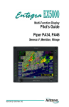
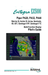
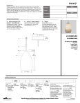
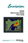
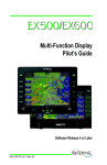
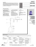
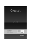
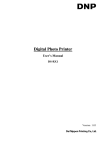
1
TeKnol Ltd. Vvedenskogo str., 13 “B” 117342 Moscow, RUSSIA e-mail: [email protected] http://www.teknol.ru Autonomous Portable Glass Cockpit System (PGC-A) SYSTEM OVERVIEW October 2009 TABLE OF CONTENTS Acronyms__________________________________________________________________ 3 1 Introduction____________________________________________________________ 4 2 System Description ______________________________________________________ 5 2.1 Inertial-GNSS integrated navigation system_____________________________ 5 2.2 GARMIN GPS35 ___________________________________________________ 5 2.3 Commutation unit __________________________________________________ 5 2.4 Panasonic CF-19____________________________________________________ 6 3 System specification _____________________________________________________ 7 4 System Operation _______________________________________________________ 8 5 Deployment ____________________________________________________________ 9 6 PGC functionality ______________________________________________________ 10 6.1 Data display ______________________________________________________ 6.1.1 Primary Flight Display___________________________________________ 6.1.2 Navigation Display _____________________________________________ 6.1.3 Instruments Panel_______________________________________________ 6.1.4 Combined Display ______________________________________________ 10 10 12 13 14 6.2 Flight planning ____________________________________________________ 15 6.3 In flight operations_________________________________________________ 17 6.4 Training _________________________________________________________ 18 6.5 Debriefing ________________________________________________________ 18 6.6 Warnings_________________________________________________________ 18 7 Advanced Configuration_________________________________________________ 19 8 Approbation and Approvals ______________________________________________ 20 9 System installation examples _____________________________________________ 21 Portable Glass Cockpit System Overview Rev. 12.2008 Page 2 Current document provides Portable Glass Cockpit system overview. For technical details and system operation please refer to “PGC-A. User Manual” and “CompaNav-2. System overview” documents. Acronyms AC Aircraft GNSS Global Navigation Satellite System INS Inertial Navigation System PFD Primary Flight Display PGC-A Autonomous Portable Glass Cockpit System TAWS Terrain Awareness Warning System WPT waypoint Portable Glass Cockpit System Overview Rev. 12.2008 Page 3 1 Introduction PGC-A is portable flight and navigation instrumentation system, which is fully independent from aircraft onboard systems. It includes navigation and flight data source and accumulator battery thus being fully autonomous. PGC-A can be easily mounted on any type of light aircraft or helicopter and is officially approved for use on Mi8 and Mi17 type of helicopters (see Approbation and Approvals section of this document). PGC-A implements intuitive indication and advanced data processing and display functions to increase flight safety and situational awareness. PGC-A provides the whole range of flight preparation, inflight and post mission operations to enhance the functionality of an aircraft without cockpit modernization. PGC-A functionality: 1. 2. 3. 4. 5. 6. 7. 8. 9. 10. 11. 12. 13. 14. 15. Flight preparation and simulation Data bases: routes, maps, digital terrain, approaches, obstacles, navigation points Primary flight display (PFD) with 3D obstacles and flight trajectory indication Navigation display (ND) and moving map Standard instruments display Forward-looking 3D views of terrain TAWS Terrain color change according to the flight altitude Predictive flight guidance Quick charts and digital terrain maps upload Quick enroute marking of obstacles and navigation points “Hovering” mode (for helicopters) AS/SI measurement systems Approach and landing pattern programming Visual and audible warnings about dangerous flight or aircraft limitations override Portable Glass Cockpit System Overview Rev. 12.2008 Page 4 2 System Description The PGC-A standard architecture includes the following units: Inertial-GNSS integrated Navigation System Garmin GPS Smart Antenna, Model GPS35-LVC Ruggedized Tablet PC CF-19 with Windows OS and special PGC-A Software Commutation unit with built-in battery 2.1 Inertial-GNSS integrated navigation system The integrated inertial-GNSS navigation system is motion parameters data source for the PGC-A. The system determines position coordinates (latitude, longitude and height) and attitude angles (pitch, roll and heading) of an aircraft. The system outputs 50Hz rate navigation data to the Panasonic CF-19 computer where it is processed and displayed. 2.2 GARMIN GPS35 The GARMIN GPS 35 is a GPS receiver with built-in antenna. GPS35 tracks up to 12 satellites at a time, provides fast time-tofirst-fix and 1Hz navigation updates. It is housed into waterresistant case and designed to withstand rugged operating conditions. All settings of GARMIN GPS35 are made by the manufacturer. The receiver does not require service or maintenance through its life cycle. 2.3 Commutation unit The commutation unit provides PGC-A system units data and power interconnection. To provide system power supply it is connected to onboard power circuit. The unit also incorporates built-in accumulator battery and guarantees 2,5 hours of PGC-A autonomous work. The LED indicators in front panel indicate the battery charge and system state. Portable Glass Cockpit System Overview Rev. 12.2008 Page 5 2.4 Panasonic CF-19 The Panasonic Toughbook CF-19 is a ruggedized laptop computer, which was designed and tested in accordance with MIL-STD-810F. Panasonic Toughbook meets all the categories and levels of durability expected in the work environment of a cockpit: vibration, drop, water and dust resistance, humidity, high and low temperature, altitude. As part of PGC-A the Panasonic CF-19 provides flight data processing, displaying, management and recording. Panasonic CF19 runs special PGC-A software to provide mission planning and flight data analysis functions. Portable Glass Cockpit System Overview Rev. 12.2008 Page 6 3 System specification Inertial-GNSS integrated system Specification Operating rages Angular velocity Acceleration Pitch Roll Heading ±300˚/sec ±6g ±90˚ ±90˚ 0..360˚ Interface Update rate Warm-up time Operating temperature Shock Input voltage Power RS232 50 Hz 30 sec -40..+70˚С 20g 8-30 V <1,5 W Size Weight 125х80х57 mm 0,7 kg Panasonic CF-19 (MIL-STD-810F) Intel Core Duo 1,06 GHz HDD 80 Gb RAM 1,5 Gb RS 232 Brightness 500 nit Portable Glass Cockpit System Overview Power 60 W Operating temperature 0..+60˚C Storage temperature -40..+60˚C Weight 2,3 kg Rev. 12.2008 Page 7 4 System Operation 1. 2. 3. 4. 5. 6. 7. Inertial Navigation System Tablet PC GPS receiver Garmin 35 Commutation unit Solid-state Flight Data Recorder (option) Air Data Computer (option) External Switch Figure 1 PGC-A basic architecture The GPS receiver NMEA data and inertial sensors data are processed by the inertial navigation system microprocessor to calculate motion parameters and navigation data, which are output to the tablet PC via RS 232 interface with 50 Hz rate. Then the data are processed and visualized by the PGC-A software. If the Air Data Computer is available, the airspeed data is also used for motion parameters calculation. The flight data are displayed with respect to moving map and 3D digital terrain. The software also calculates forecast vectors of motion acceleration, motion speed and altitude vectors, flight direction and provides warnings in case of dangerous flight. Software is controlled by the means of touch-screen display to provide quick display of the required data. The same tablet PC is used for flight planning and for flight data analysis. Normally the flight data is stored in the PC hard drive, but as backup data storage the solid-state Flight Data Recorder can be used. Portable Glass Cockpit System Overview Rev. 12.2008 Page 8 5 Deployment System deployment is easy and does not require complicated installation procedures. The deployment consists of three basic stages: 1) Mounting 2) Unit interconnection 3) Powering up All units should be located within the aircraft in accordance with the following considerations: A) The ideal location for integrated inertial-GNSS navigation system unit is close to the centre of mass of the aircraft. The unit must be placed on a horizontal surface so that its led indicators are on the top and point in the rear direction. The system is tolerant to misalignments between unit axis and longitudinal aircraft axis of up to ±5◦. B) The location of GPS antenna should ensure a clear view of the sky. C) The cables should not run adjacent to heaters, exhausts or other heat sources. Care must be taken to route and tie the cables away from aircraft controls and harnesses. D) The tablet PC shall be in view of pilot and its location must provide the free access of pilot’s hand to the screen. However, it should not create an obstruction to the field of view of the instrument panel. The tablet PC should be easily installed and removed to allow flight planning and post-flight analysis on the ground. E) The commutation unit should be easily accessible and dismountable to allow battery re-charging on the ground. After units are properly arranged and fixed they must be connected with proper cables according to the cable labels. Then the commutation unit must be connected to the board power supply circuit. Portable Glass Cockpit System Overview Rev. 12.2008 Page 9 6 PGC functionality PGC-A software provides the functionality of several avionics instruments and systems, including TAWS, EFIS and Electronic Flight Bag. The PGC-A is capable to perform the whole range of flight operations, including flight preparation (flight planning), route, map, airfield data base creation, inflight operations (flight director, approaches, obstacles marking, etc.), post mission flight data analysis. 6.1 Data display The navigation data, motion parameters and trajectory can be displayed in one of the following ways: - in 3D image with digital terrain as background (Primary Flight Display, PFD) in 2D image (Navigation Display) with digital terrain, map, approach pattern or aerial image as background in standard gauges (instrumental panel) in combined image (3D+2D, 3D+map, 3D+instrumental panel, instrumental panel+map) The type of data indication is selected by the button in the lower corner of the PGC window. 6.1.1 Primary Flight Display The default indication mode is PFD. It displays all standard flight instrumentation as graphical objects: aircraft symbol, rulers, vectors, etc. Figure 2 shows PGC-A PFD. Attitude, heading, ground speed, rate of climb, altitude, G-load are displayed. The aircraft symbol depicts the actual attitude of the aircraft with respect to horizon. While flying, flight director cross marks the flight direction according to the desired flight plan. When circle of the forecast vector of acceleration (see Figure 2) matches the flight director cross, the aircraft won’t deviate from the programmed route. Desired speed and height values are marked at the scales to the right and to the left. Portable Glass Cockpit System Overview Rev. 12.2008 Page 10 Figure 2: Primary Flight Display The digital terrain data is overlaid as colored three dimensional image on both PFD display and Navigation Display. The PGC-A software applies color coding of the terrain data. The above-flight-level terrain is coloured red, while the below-flight-level terrain is green. According to terrain data the terrain proximity line is calculated and displayed in 3D PFD view. Terrain proximity line along with 3D terrain display function and warnings about aircraft operating limitations increase pilot situation awareness, thus TAWS function is implemented. Portable Glass Cockpit System Overview Rev. 12.2008 Page 11 6.1.2 Navigation Display The Navigation Display shows planned trajectory, predicted path, and turn limitation. The aircraft shape is displayed as a cross with the arrow pointing in the direction of flight. In the Navigation Display can be displayed digital map or 2D terrain. Figure 3: Navigation Display PGC-A software provides raster images georeferencing in order to create digital maps of topographical map images, aerial photos and approach charts meeting the user requirements. Figure 4: Navigation display with moving map Portable Glass Cockpit System Overview Rev. 12.2008 Page 12 6.1.3 Instruments Panel Instruments Panel Display simulates the following standard avionics instruments: Artificial horizon Heading Indicator (HSI) Altimeter Climb meter Ground speed indicator G-meter Low altitude altimeter Figure 5: Instrument Panel Portable Glass Cockpit System Overview Rev. 12.2008 Page 13 6.1.4 Combined Display To enhance data indication flexibility and convenience, several types of combined displays are provided: 3D+2D, 3D+navigation instruments, navigation instruments + map (see Figure 6). 3D+2D (terrain) 3D+map (aerial image) 3D+navigation instruments Navigation instruments+map Figure 6: Combined View displays Portable Glass Cockpit System Overview Rev. 12.2008 Page 14 6.2 Flight planning PGC-A software provides the user with extensive flight planning capacity. The database of routes can be formed prior the flight in the office or workshop, when the portable computer is dismounted from the aircraft cockpit. For the flight planning digital maps and digital terrain maps can be used. Route comprises: waypoints airfields approaches obstacles navigation points maps terrain All the elements of the route can be loaded from the data base or created before the flight. The route is created considering the digital terrain data. The flight planning software comprises approach planning options based on standard approach patterns and user updated obstacle data base. The taxing and aircraft parking planning is also available. The airport data base includes the approach and taxing charts, runway numbers (glideslope courses), radio link and frequency-response data. Figure 7: Flight planning Portable Glass Cockpit System Overview Rev. 12.2008 Page 15 Figure 8: Aerodrome chart Portable Glass Cockpit System Overview Rev. 12.2008 Page 16 6.3 In flight operations The PGC-A tablet PC communicates with INS unit via a high-speed RS-232 interface. 50Hz standard data update rate provides uninterrupted flight parameters indication under any flight conditions. By processing the navigation data from inertial navigation system and air data computer (optionally) the PGC software calculates and displays terrain proximity line, current motion trajectory and motion forecast vectors, motion director and deviations from the desired flight plan, etc. Along with standard instrumentation, PGC-A significantly increases pilot’s situation awareness by displaying the circle of operational limitations and the integral force, which is the primary cause of aircraft motion. The PGS-A offers a wide range of extended performance allowing a pilot to operate and navigate the aircraft with maximum convenience and safety using advantages of modern computer and database technologies. The PGC-A software is adapted for control by the means of tablet PC touch screen. Along with data indication, trajectory visualization, TAWS and warning function during the flight the PGC provides: quick route change (“GO TO” function) approach pattern display and approach director quick landing to the site marked during the flight quick obstacle marking. The obstacles are marked inlfight as a point in the map. After the flight the obstacle height should be set and the obstacle must be stored in the data base. In the next flight the obstacle with a cone zone of danger around it will be marked in PFD as a 3D object. Portable Glass Cockpit System Overview Rev. 12.2008 Page 17 6.4 Training The PGC-A allows user getting familiar with system performance before flight. A set of joysticks turns the PGC-A into a compact desktop simulator. As a simulator the PGC-A provides two functions: 1) Learning basic system operation 2) Flight preparation: once flight plan is ready the pilot can perform the virtual flight, following selected trajectory, learning navigation over a particular area of the forthcoming flight. 6.5 Debriefing All the data coming from INS can be recorded in the tablet PC. The system allows simultaneous recording of more then 30 flight parameters, including pitch, roll, heading angles, speed, coordinates, altitude and barometric height, GPS data and other. The PGC-A software has an advanced capacity for debriefing and post mission flight data analysis. The system is capable to playback the flight data with different time scales. 6.6 Warnings In flight the PGC-A software analyses the aircraft motion parameters and compares it with operating limitations set for the aircraft. In case flight parameters are close to the limitations or are violating the set values, visual and audible warning signals are provided. The visual warnings are displayed in the panel of warnings in the upper corner of the program screen (Figure 9). Figure 9: Panel of warnings To provide visual warning, the appropriate button in the panel is coloured red. If the danger occurs, the button is coloured red. Portable Glass Cockpit System Overview Rev. 12.2008 Page 18 7 Advanced Configuration 1. 2. 3. 4. 5. 6. Inertial System Panasonic CF-19 GPS Garmin 35 Commutation unit Flight Data Recorder (Optional) Air Data System (Optional) The advanced configuration includes 2 tablet computers (one for pilot and one for pilotnavigator) and 2 inertial system units to provide instruments backup. Advanced configuration provides the extended system capability, including networking interoperations between two computers. For example, the pilot-navigator can perform all inflight operations and control the pilot computer display to provide better situation awareness, thus pilot won’t need to control the display himself. Portable Glass Cockpit System Overview Rev. 12.2008 Page 19 8 Approbation and Approvals The PGC-A is officially approved by Russian Flight Administration and MiL helicopter plant for use as additional navigation system for Mi8, Mi17 types of helicopters in use. Figure 10: PGC-A List of Approval The document states the following: 1. PGC-A keeps its navigation functionality even if GPS data are corrupted or missed for short period of time (2…4 min). 2. The integration of INS and GPS data provides the better flight parameters determination especially while moving with low speed: a. The satellite data jumps due to change of constellation are smoothed with inertial data b. The satellite data latency is compensated with inertial sensors data. 3. The standard GPS data rate (1Hz) is increased up to 50 updates per second 4. The mobile tablet PC with bright display (10,4”, 500 nit) provides up to 2,5 hrs of autonomous system work. 5. The system can be located in the appropriate place of the cockpit of Mi8(Mi17) helicopter, providing convenient operations for flight crew. 6. The use of the PGC-A does not affect the basic properties of the vessel, its standard communication and navigation equipment 7. The use of PGC-A does not require to revise the helicopter flight operation manuals neither maintenance procedures. 8. In case of emergency situation the PGC-A does not change the standard sequence of flight crew operations and does not handicap to abandon ship in emergency Starting 2006 the PGC-A is used by helicopter operators in Russia and abroad. The PGC-A is operated in Nepal, Afghanistan, Kazakhstan for UN mission flight support. Portable Glass Cockpit System Overview Rev. 12.2008 Page 20 9 System installation examples Mi8 helicopter Portable Glass Cockpit System Overview Rev. 12.2008 Page 21 Mi26 Helicopter Portable Glass Cockpit System Overview Rev. 12.2008 Page 22 Mi2 helicopter Robinson R-44 helicopter Mi-24(Mi-35) Portable Glass Cockpit System Overview Rev. 12.2008 Page 23 L410 airplane Yak-18T airplane Portable Glass Cockpit System Overview Rev. 12.2008 Page 24 Sigma-4 light airplane Portable Glass Cockpit System Overview Rev. 12.2008 Page 25