1
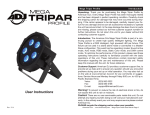
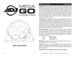
Tri Disc 9 IR Tri Disc 9 IR
Introduction
Unpacking: Thank you for purchasing the Tri Disc 9 IR by Eliminator Lighting. Every Tri Disc 9 IR has been thoroughly tested and has
been shipped in perfect operating condition. Carefully check the shipping carton for damage that may have occurred during shipping. If the
carton appears to be damaged, carefully inspect your fixture for any
damage and be sure all accessories necessary to operate the unit has
arrived intact. In the case damage has been found or parts are missing, please contact our toll free customer support number for further
instructions. Do not return this unit to your dealer without first contacting customer support.
Introduction: The Tri Disc 9 IR can be used in a stand alone mode or
connected in a Master/Slave configuration. This wash has five operating modes: Sound Active mode, Auto Run mode, RGB mode, Static
Color mode, and DMX control mode.
Warning! To prevent or reduce the risk of electrical shock or fire, do
not expose this unit to rain or moisture.
Caution! There are no user serviceable parts inside this unit. Do not
attempt any repairs yourself, doing so will void your manufactures warranty. In the unlikely event your unit may require service please contact
Eliminator Lighting.
PLEASE recycle the shipping carton when ever possible.
Tri Disc 9 IR
User Instructions
3/14
Warranty
Eliminator Lighting warranty is valid from the date of purchase. Our 1
year limited warranty covers manufacturing defects only. Serial number, place of purchase with dated valid receipt must be submitted
at time of service. Eliminator Lighting warranty does not cover items
or parts prone to wear and tear: motors, fuses, brushes and belts.
Eliminator Lighting warranty is only valid with-in the United States.
Eliminator Lighting - www.eliminatorlighting.com - Tri Disc 9 IR User Manual - Page 2
Tri Disc 9 IR
Safety Precautions
Tri Disc 9 IR
Set Up
•To reduce the risk of electrical shock or fire, do not expose this unit rain or moisture
•Do not spill water or other liquids into or on to your unit.
•Do not attempt to operate this unit if the power cord hasbeen
frayed or broken. Do not attempt to remove or break off the ground
prong from the electrical cord. This prong is used to reduce the risk of electrical shock and fire in case of an internal short.
•Disconnect from main power before making any type of connection.
• Do not remove the cover under any conditions. There are no user serviceable parts inside.
•Never operate this unit when it’s cover is removed.
•Never plug this unit in to a dimmer pack
•Always be sure to mount this unit in an area that will allow proper ventilation. Allow about 6” (15cm) between this device and a wall.
•Do not attempt to operate this unit, if it becomes damaged.
•This unit is intended for indoor use only, use of this product out`
doors voids all warranties.
•During long periods of non-use, disconnect the unit’s main power.
•Always mount this unit in safe and stable matter.
•Power-supply cords should be routed so that they are not likely to be walked on or pinched by items placed upon or against them, paying particular attention to the point they exit from the unit.
• Cleaning -The fixture should be cleaned only as recommended by the manufacturer. See page 25 for cleaning details.
•Heat -The appliance should be situated away from heat sources such as radiators, heat registers, stoves, or other appliances (including amplifiers) that produce heat.
•The fixture should be serviced by qualified service personnel when:
A. The power-supply cord or the plug has been damaged.
B. Objects have fallen, or liquid has been spilled into the appliance.
C. The appliance has been exposed to rain or water.
D. The appliance does not appear to operate normally or exhibits a marked change in performance.
Power Supply: The Tri Disc 9 IR contains a automatic voltage switch,
which will auto sense the voltage when it is plugged into the power
source. With this switch there is no need to worry about the correct
power voltage, this unit can be plugged in anywhere.
Eliminator Lighting - www.eliminatorlighting.com - Tri Disc 9 IR User Manual - Page 3
Eliminator Lighting - www.eliminatorlighting.com - Tri Disc 9 IR User Manual - Page 4
DMX-512: DMX is short for Digital Multiplex. This is a universal pro-
tocol used as a form of communication between intelligent fixtures
and controllers. A DMX controller sends DMX data instructions from
the controller to the fixture. DMX data is sent as serial data that travels from fixture to fixture via the DATA “IN” and DATA “OUT” XLR terminals located on all DMX fixtures (most controllers only have a DATA
“OUT” terminal).
DMX Linking: DMX is a language allowing all makes and models of
different manufactures to be linked together and operate from a single
controller, as long as all fixtures and the controller are DMX compliant. To ensure proper DMX data transmission, when using several
DMX fixtures try to use the shortest cable path possible. The order
in which fixtures are connected in a DMX line does not influence the
DMX addressing. For example; a fixture assigned a DMX address of 1
may be placed anywhere in a DMX line, at the beginning, at the end,
or anywhere in the middle. When a fixture is assigned a DMX address
of 1, the DMX controller knows to send DATA assigned to address 1
to that unit, no matter where it is located in the DMX chain.
Data Cable (DMX Cable) Requirements (For DMX Operation):
The Tri Disc 9 IR can be controlled via DMX-512 protocol. The Tri Disc 9
IR has 7 DMX channel modes, please see pages 12-13 for the different
modes. The DMX address is set on the back panel of the Tri Disc 9 IR.
Your unit and your DMX controller require a standard 3-pin XLR connector for data input and data output (Figure 1). We
recommend Accu-Cable DMX cables. If you are
making your own cables, be sure to use standard
110-120 Ohm shielded cable (This cable may be
purchased at almost all pro lighting stores). Your
cables should be made with a male and female
XLR connector on either end of the cable. Also
remember that DMX cable must be daisy chained
Figure 1
and cannot be split.
Tri Disc 9 IR
Set Up
POWER
POWER
Notice: Be sure to DMX512
follow figures two and three when making your own
cables. Do not DMX+,DMX-,COMMON
use the ground lug on the XLR connector. Do not connect the cable’s shield conductor to the ground lug or allow the shield
conductor to come in contact with the XLR’s outer casing. Grounding
the shield could cause a short circuit and erratic behavior.
COMMON
1
DMX512 OUT
3-PIN XLR
REMOTE
CONTROL
INPUT
UND
INPUT
2
OUTPUT
3
DMX -
1
2
SOUND
XLR Female Socket
XLR Male Socket
1 Ground
DMX +
3
2 Cold
2 Cold
1 Ground
DMX512 IN
3-PIN XLR
REMOTE
CONTROL
INPUT
INPUT
3
1
2
Figure 2
OUTPUT
XLR Pin Configuration
Pin 1 = Ground
Figure 3
3 Hot
Pin 3 = Data True (positive)
POWER
POWER
Special Note: Line Termination. When longer runs of cable are
3
1
2
used, you may need to use a terminator on the last unit to avoid erratic
behavior. A terminator is a 110-120 ohm 1/4 watt resistor which is connected between pins 2 and 3 of a male XLR connector (DATA + and
DATA -). This unit is inserted in the female XLR connector of the last
unit in your daisy chain to terminate the line. Using a cable terminator
(ADJ part number Z-DMX/T) will decrease the possibilities of erratic
behavior.
Termination reduces signal errors and
DMX512 IN
3-PIN XLR
3
avoids signal transmission problems
and interference. It is always advisable
to connect a DMX terminal, (Resistance
120 Ohm 1/4 W) between PIN 2 (DMX-)
and PIN 3 (DMX +) of the last fixture.
1
2
Figure 4
5-Pin XLR DMX Connectors. Some manufactures use 5-pin DMX-
512 data cables for DATA transmission in place of 3-pin. 5-pin DMX
fixtures may be implemented in a 3-pin DMX line. When inserting standard 5-pin data cables in to a 3-pin line a cable adaptor must be used,
these adaptors are readily available at most electric stores. The chart
below details a proper cable conversion.
3-Pin XLR to 5-Pin XLR Conversion
Conductor
3-Pin XLR Female (Out)
5-Pin XLR Male (In)
Ground/Shield
Pin 1
Pin 1
Data Compliment (- signal)
Pin 2
Pin 2
Data True (+ signal)
Pin 3
Pin 3
Not Used
Do Not Use
Not Used
Do Not Use
Eliminator Lighting - www.eliminatorlighting.com - Tri Disc 9 IR User Manual - Page 5
POWER
Operating Instructions
LED Display On/Off:
To set the LED display to turn off after 60 seconds, press the MODE
button until “don” is displayed, press the UP button to display “doff”.
Now the display will disappear after 60s. Press any button to turn
the display on again. Be advised though that the display will turn off
automatically after 10 seconds.
Termination reduces signal errors and
avoids signal transmission problems
and interference. It is always advisable
to connect a DMX terminal, (Resistance
120 Ohm 1/4 W) between PIN 2 (DMX-)
and PIN 3 (DMX +) of the last fixture.
Pin 2 = Data Compliment (negative)
3 Hot
Tri Disc 9 IR
To set the display press the MODE button until “dXX” is displayed.
Use the UP or DOWN buttons to select either:
“don” = LED display on at all times.
“doFF” = LED display shuts off after 60 seconds.
LED Display Inversion:
Follow these instructions to flip the display 180° so that the display can
be read upside down.
1. Plug the fixture in and press the MODE button until “dXX” is dis- played. “XX” represents either “on” or “oFF”.
2. Press the SET UP button until “Stnd” or “rev” is displayed.
3. Press the UP or DOWN buttons to reverse the display 180°.
Operating Modes:
The Tri Disc 9 IR has five operating modes:
• Sound-Active mode - The unit will react to sound, chasing through
the
built in programs.
• Static Color Mode - There are 35 colors to choose from.
• RGB Dimmer Mode - Choose one of the three colors to remain static or adjust the intensity of each color to make your desired color.
• Auto Run Mode - The unit will run 1 of 16 color change pro-
grams at your desired speed.
• DMX control mode - This function will allow you to control each
individual fixtures traits with a standard DMX 512 controller such as
as the ADJ Show Designer™.
RGB Dimmer Mode:
1. Plug the fixture in and press the MODE button until:
2. When “r.XXX” is displayed you are in Red dimming mode. Press the UP and DOWN buttons to adjust intensity.
Eliminator Lighting - www.eliminatorlighting.com - Tri Disc 9 IR User Manual - Page 6
Tri Disc 9 IR
Operating Instructions
3. When “G.XXX” is displayed you are in Green dimming mode. Press the UP and DOWN buttons to adjust intensity.
4. When “b.XXX” is displayed you are in Blue dimming mode. Press the UP and DOWN buttons to adjust intensity.
5. After you have adjusted the RGB colors to make your desired color you can then activate strobing by pressing the SET UP but-
ton to enter the Flash (strobe) mode.
6. “FS.XX” will be displayed, this is Flash mode. The Flash can be
adjusted between “FS.00” (flash off) to “FS.15” (fastest flash).
Sound Active Mode:
In this mode the unit will react to sound, and chase through the different colors.
1. Plug the fixture in and press the MODE button until “SoXX” is dis-
played. “X” represents the sound active mode (1-15) currently dis-
played.
2. The fixture will now change via sound.
3. Press the SET UP button to adjust the sound sensitivity. “SJ-X” should be displayed. Use the UP or DOWN buttons to adjust the
sensitivity. “SJ-1” is the least sensitivity, “SJ-8” is the most.
Tri Disc 9 IR
Operating Instructions
the instructions. Set your color fade speed and set the color change speed to “SP.01”.
Static Color Mode:
1. Plug the fixture in and press the MODE button until “CL.XX” is displayed. “XX” represents the current color number displayed.
2. There are 35 colors to choose from. Select your desired color by pressing the UP and DOWN buttons. After you have selected
your desired color you can activate strobing by pressing the SET UP button to enter the Flash (strobe) mode.
3. “FS.XX” will be displayed, this is Flash mode. The Flash can be
adjusted between “FS.00” (flash off) to “FS.15” (fastest flash).
Auto Run Mode:
In this mode the Tri Disc 9 will run 1 of 16 auto programs. The auto
run program can be either a fade program or a simple color change
program.
1. Plug the fixture in and press the MODE button until “APXX” is dis-
played. “XX” represents the program number (1-16) currently dis-
played.
2. After you have chosen your desired program you need to decide if you would like the program to fade through colors or simply change. Press the SET UP button until either “SP.XX” (color
change) or “F-XX” (color fade) is displayed.
3. If you select color change, use the UP and DOWN buttons to adjust the speed between “SP.01” (slowest) and “SP.99” (fastest). Once you have set your desired color change speed, press the SET UP button to move on to “F-XX” (color fade). Use the UP or DOWN buttons to set the color fade speed to “F-00”. This means
the color fade is off, and the fixture will now color change at the speed you have set. To run the fixture in color fade, reverse DMX Mode:
Operating through a DMX controller gives the user the freedom to
create their own programs tailored to their own individual needs. This
function also allows you to use your fixtures as spot lights. The Tri
Disc 9 IR has 7 DMX modes: 1 Channel mode, 2 Channel mode, 3
Channel mode, 4 Channel mode, 5 Channel mode, 6 Channel mode,
and a 7 Channel mode. See pages 13-15 for each modes’ DMX traits.
1. This function will allow you to control each individual fixture’s traits with a standard DMX 512 controller.
2. To run your fixture in DMX mode press the MODE button until “d.XXX” is displayed. “XXX” represents the current displayed address. Use the UP or DOWN buttons to select your desired DMX address. then press the SET UP button to select your DMX
Channel mode.
3. When you press SET UP “ChXX” should be displayed. “XX” repre-
sent the current DMX Channel Mode.
4. Use the UP or DOWN buttons to scroll through the DMX Channel modes. The Channel modes are listed below:
• To run the 1 Channel Mode, press the MODE button until “Ch01” is displayed. This is the 1 Channel DMX Mode.
• To run the 2 Channel Mode, press the MODE button until “Ch02” is displayed. This is the 2 Channel DMX Mode.
• To run the 3 Channel Mode, press the MODE button until “Ch03” is displayed. This is the 3 Channel DMX Mode.
• To run the 4 Channel Mode, press the MODE button until “Ch04” is displayed. This is the 4 Channel DMX Mode.
Eliminator Lighting - www.eliminatorlighting.com - Tri Disc 9 IR User Manual - Page 7
Eliminator Lighting - www.eliminatorlighting.com - Tri Disc 9 IR User Manual - Page 8
Tri Disc 9 IR
Operating Instructions
• To run the 5 Channel Mode, press the MODE button until “Ch05” is displayed. This is the 5 Channel DMX Mode.
• To run the 6 Channel Mode, press the MODE button until “Ch06” is displayed. This is the 6 Channel DMX Mode.
• To run the 7 Channel Mode, press the MODE button until “Ch07” is displayed. This is the 7 Channel DMX Mode.
5. Please see pages 13-17 for DMX values and traits.
6. After you have chosen your desired DMX Channel mode plug in the fixture via the XLR connections to any standard DMX control-
ler.
Default Running Mode:
This is a default running mode. When this mode is activated all modes
will return to their default settings.
1. Plug the fixture in and press the MODE button until “dXX” is dis- played. “XX” represents either “on” or “oFF”.
2. Press the SET UP button until “dEFA” is displayed.
3. Press the UP and DOWN buttons simultaneously. Press the MODE button to exit.
Tri Disc 9 IR
Master-Slave Configuration
Master-Slave Configuration:
This function will allows you to link units together to run in a Master-Slave
mode. In Master-Slave operation one unit will act as the controlling unit
and the others will react to the controlling units built-in programs. Any
unit can act as a Master or as a Slave however, only one unit can be programmed to act as the “Master.”
Master-Slave Connections and Settings:
1. Daisy chain your units via the XLR connector on the rear of the unit. Use standard XLR data cables to link your units together. Remember
that the Male XLR connector is the input and the Female XLR con-
nector is the ouput. The first unit in the chain (master) will use the female XLR connector only. The last unit in the chain will use the male XLR connector only.
2. Set the “Master” unit to your desired mode of operation.
3. For the “Slave” units just connect them to the “Master”, they will start following the “Master” as soon as they are connected.
Electro IRC:
This function is used to activate and deactivate the Electro IRX
(Remote Control). When this function is activated you can control the
fixture using the Electro IRC. Please see the page 11 for the controls
and functions.
1. Plug the fixture in and press the MODE button until “dXX” is dis- played. “XX” represents “on” or “off”.
2. Press the SET UP button until “IrXX” is displayed. “XX” repre-
sents either “on” or “oF”.
3. Press the UP or DOWN buttons to either activate the remote func-
tion (On) or deactivate it (Off).
Eliminator Lighting - www.eliminatorlighting.com - Tri Disc 9 IR User Manual - Page 9
Eliminator Lighting - www.eliminatorlighting.com - Tri Disc 9 IR User Manual - Page 10
Tri Disc 9 IR
Electro IRC Operation
The Electro IRC remote (sold seperately) has many different functions
and allows you to control your Tri Disc 9 IR from long distance. The
Electro IRC remote can control your system up to 30 ft. To use the remote you must first activate the fixtures receiver, to activate the receiver
please see the instructions on page 9.
Controls and Functions:
1. Black Out - This button will black out the unit.
2. Select Prog - This button will allow you to access the auto
run mode and built in programs. Each press of the button will
change to the next mode.
3. Flash - This button will activate the strobe function. Use the
“+” & “-” buttons to adjust the strobe speed.
4. SPEED - Press this button to activate and use the “+” & “-”
buttons to adjust the speed of the color fade mode and color
change mode.
5. DMX Mode - Activates DMX Mode.
6. Set Addr - Press this button to set the DMX address. Press
this button first, then press the numbers to set the address.
Example: Set DMX Address 1 Press “S-0-0-1”
Set DMX Address 245 Press “S-2-4-5”
7. SL/SA (Slave/Sound Active) - This button lets you switch
between Slave mode in a Master-Slave configuration and Sound
Active mode. When the fixture is in Sound Active mode, use the
“+” & “-” buttons to adjust the sound sensitivity.
8. R G B A W - Press either one of these buttons and the press
the “+” or “-” to adjust the brightness. Press the Flash Button
to activate strobing and use the “+” & “-” buttons to adjust the
strobe speed. The “A” & “W” buttons will not work with this unit.
9. “+” and “-” - Use these buttons to adjust the flash rate
speed, program speed, sound sensitivity, and program selection.
Eliminator Lighting - www.eliminatorlighting.com - Tri Disc 9 IR User Manual - Page 11
Tri Disc 9 IR
Channel
1
Value
0 - 10
11 - 17
18 - 24
25 - 31
32 - 38
39 - 45
46 - 52
53 - 59
60 - 66
67 - 73
74 - 80
81 - 87
88 - 94
95 - 101
102 - 108
109 - 115
116 - 122
123 - 129
130 - 136
137 - 143
144 - 150
151 - 157
158 - 164
165 - 171
172 - 178
179 - 185
186 - 192
193 - 199
200 - 206
207 - 213
214 - 220
221 - 227
228 - 234
235 - 241
242 - 248
249 - 255
1 Channel - DMX Values & Functions
Function
COLOR MACROS
OFF
BASTARD AMBER
MEDIUM AMBER
PALE AMBER GOLD
GALLO GOLD
GOLDEN AMBER
LIGHT RED
MEDIUM RED
MEDIUM PINK
BROADWAY PINK
FOLLIES PINK
LIGHT LAVENDER
SPECIAL LAVENDER
LAVENDER
INDIGO
HEMSLEY BLUE
TIPTON BLUE
LIGHT STEEL BLUE
LIGHT SKY BLUE
SKY BLUE
BRILLIANT BLUE
LIGHT GREEN BLUE
BRIGHT BLUE
PRIMARY BLUE
CONGO BLUE
PALE YELLOW GREEN
MOSS GREEN
PRIMARY GREEN
DOUBLE CTB
FULL CTB
HALF CTB
DARK BLUE
WHITE
FULL RED
FULL GREEN
FULL BLUE
Eliminator Lighting - www.eliminatorlighting.com - Tri Disc 9 IR User Manual - Page 12
Tri Disc 9 IR
Channel
Value
1
0 - 255
2
0 - 255
Tri Disc 9 IR
Channel
1
2
3
1
2
3
4
Function
COLOR MACROS
(See 1 Channel DMX mode for colors)
DIMMER 0% - 100%
3 Channel - DMX Values & Functions
Value
0 - 255
0 - 255
4 Channel - DMX Values & Functions
Value
0 - 255
0 - 255
0 - 255
0 - 255
Function
RED
0% - 100%
GREEN
0% - 100%
BLUE
0% - 100%
0 - 255
Tri Disc 9 IR
Channel
2 Channel - DMX Values & Functions
Function
RED
0% - 100%
GREEN
0% - 100%
BLUE
0% - 100%
MASTER DIMMER
0% - 100%
Eliminator Lighting - www.eliminatorlighting.com - Tri Disc 9 IR User Manual - Page 13
Tri Disc 9 IR
Channel
Value
5 Channel - DMX Values & Functions
Function
1
RED
1 - 255
0% - 100%
2
GREEN
1 - 255
0% - 100%
3
BLUE
1 - 255
0% - 100%
4
MASTER DIMMER
1 - 255
0% - 100%
5
1 - 255
COLOR MACROS
(See 1 Channel DMX mode for colors)
Channels 1, 2, and 3 will not work, when Channel 5 is being
used.
Tri Disc 9 IR
Channel
1
Value
6 Channel - DMX Values & Functions
Function
RED
0% - 100%
2
GREEN
1 - 255
0% - 100%
3
BLUE
1 - 255
0% - 100%
4
1 - 255
COLOR MACROS
(See 1 Channel DMX mode for colors)
5
STROBING
0 - 15
NOTHING
16 - 255
STROBING SLOW - FAST
6
MASTER DIMMER
1 - 255
0% - 100%
Channels 1, 2, and 3 will not work, when Channel 4 is being
used.
1 - 255
Eliminator Lighting - www.eliminatorlighting.com - Tri Disc 9 IR User Manual - Page 14
Tri Disc 9 IR
Channel
1
2
3
4
5
6
Value
1 - 255
1 - 255
1 - 255
1 - 255
0 - 15
16 - 255
0-7
8 - 15
16 - 23
24 - 31
32 - 39
40 - 47
48 - 55
56 - 63
64 - 71
72 - 79
80 - 87
88 - 95
96 - 103
104 - 111
112 - 119
120 - 127
128 - 135
136 - 143
144 - 151
152 - 159
160 - 167
7 Channel - DMX Values & Functions
Function
RED
0% - 100%
GREEN
0% - 100%
BLUE
0% - 100%
COLOR MACROS
(See 1 Channel DMX mode for colors)
STROBING/PROGRAM SPEED
NOTHING
STROBING/SPEED CONTROL
SLOW - FAST
PROGRAMS/SOUND ACTIVITY
OFF
PROGRAM 1
PROGRAM 2
PROGRAM 3
PROGRAM 4
PROGRAM 5
PROGRAM 6
PROGRAM 7
PROGRAM 8
PROGRAM 9
PROGRAM 10
PROGRAM 11
PROGRAM 12
PROGRAM 13
PROGRAM 14
PROGRAM 15
PROGRAM 16
SOUND MODE 1
SOUND MODE 2
SOUND MODE 3
SOUND MODE 4
Eliminator Lighting - www.eliminatorlighting.com - Tri Disc 9 IR User Manual - Page 15
Tri Disc 9 IR
Channel
6
7
Value
168 - 175
176 - 183
184 - 191
192 - 199
200 - 207
208 - 215
216 - 223
224 - 231
232 - 239
240 - 247
248 - 255
1 - 255
7 Channel - DMX Values & Functions
Function
PROGRAMS/SOUND ACTIVITY
SOUND MODE 5
SOUND MODE 6
SOUND MODE 7
SOUND MODE 8
SOUND MODE 9
SOUND MODE 10
SOUND MODE 11
SOUND MODE 12
SOUND MODE 13
SOUND MODE 14
SOUND MODE 15
MASTER DIMMER
0% - 100%
Channels 1, 2, and 3 will not work, when Channel 4 is being used.
When using Channel 6 values 8-135, Channel 5 will control the speed of the programs.
When using Channel 6 values 136-255, Channel 5 will control the sound sensitivity. Sound sensitivity control will start working after Channel 5 is past the DMX value of 31.
Eliminator Lighting - www.eliminatorlighting.com - Tri Disc 9 IR User Manual - Page 16
Tri Disc 9 IR
Warranty
1 Year Limited Warranty: Eliminator Lighting warranty is valid
Tri Disc 9 IR
Notes
from the date of purchase. Our 1 year limited warranty covers manufacturing defects only. Serial number, place of purchase with dated
valid receipt must be submitted at time of service. Eliminator Lighting
warranty does not cover items or parts prone to wear and tear: motors, fuses, brushes and belts. Eliminator Lighting warranty is only
valid with-in the United States.
Tri Disc 9 IR
Fuse Replacement
Disconnect the unit from its power source. Remove the power cord
from the unit. Once the cord has been removed, you will find that the
fuse holder is located inside the power socket. Insert a flat-head screw
driver into the power socket and gently pry out the fuse holder. Remove
the bad fuse and replace with a new one. The fuse holder also has a
holder for a spare fuse.
Tri Disc 9 IR
Cleaning
Tri Disc 9 IR
Power Cord Daisy Chain
Due to fog residue, smoke, and dust cleaning the internal and external optical lenses must be carried out periodically to optimize light
output.
1. Use normal glass cleaner and a soft cloth to wipe down the
outside casing.
2. Clean the external optics with glass cleaner and a soft cloth
every 20 days.
3. Always be sure to dry all parts completely before plugging
the unit back in.
Cleaning frequency depends on the environment in which the fixture
operates (i.e. smoke, fog residue, dust, dew).
With this feature you can connect the fixtures to one another
using the IEC input and output sockets. The quantity that can be
connected is 16 fixtures maximum. After the maximum fixtures
has been reached you will need to use a new power outlet. They
must be the same fixtures. DO NOT mix fixtures.
Eliminator Lighting - www.eliminatorlighting.com - Tri Disc 9 IR User Manual - Page 17
Eliminator Lighting - www.eliminatorlighting.com - Tri Disc 9 IR User Manual - Page 18
Tri Disc 9 IR
Notes
Tri Disc 9 IR
Model: Tri Disc 9 IR
Specifications
Voltage: 100V ~ 240V/50~60Hz
LEDs:
9 x 3W TRI LEDs (RGB 3-in-1)
Beam Angle:
40 Degrees
Working Position: Any safe working position
Power Draw:
35W
Power Cord Daisy Chain:16 Fixtures Max.
Fuse:2 Amp
Weight: 3.9lbs./ 1.8Kgs.
Dimensions: 10.5” (L) x 10” (W) x 3.5” (H)
263 x 250 x 88mm
Colors:
RGB Color Mixing
DMX Channels:
7 DMX Modes: 1 Channel Mode, 2 Channel Mode, 3 Channel Mode, 4 Channel Mode, 5 Channel Mode, 6 Channel Mode, & 7 Channel Mode
Warranty:
1 Year (365 days)
Auto Sensing Voltage: This fixture contains a automatic volt-
age switch, which will auto sense the voltage when it is plugged
into the power source.
Please Note: Specifications and improvements in the design
of this unit and this manual are subject to change without any
prior written notice.
Eliminator Lighting - www.eliminatorlighting.com - Tri Disc 9 IR User Manual - Page 18