1
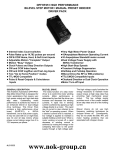
USER’S MANUAL FOR
AA1748
AA1760
AA2210
AA1754
AA2909
COPYRIGHT
Copyright 1994 by Anaheim Automation. All rights reserved. No part of this
publication may be reproduced, transmitted, transcribed, stored in a retrieval
system, or translated into any language, in any form or by any means, electronic,
mechanical, magnetic, optical, chemical, manual, or otherwise, without the prior
written permission of Anaheim Automation, 910 E. Orangefair Lane, Anaheim,
CA 92801. The only exception to this would be use of the program examples in
this manual.
COUNT INPUT MODULES
FOR
MANUAL PRESET INDEXER MODELS:
DISCLAIMER
Though every effort has been made to supply complete and accurate information
in this manual, the contents are subject to change without notice or obligation to
inform the buyer. In no event will Anaheim Automation be liable for direct,
indirect, special, incidental, or consequential damages arising out of the use or
inability to use the product or documentation.
CL1710, CL1745 Control Links
DPD65211, DPD70211, DPF65212,
DPF70212, DPFHP211, DPT10211,
DPD72211, DPF72212 Driver Packs
LIMITED WARRANTY
All Anaheim Automation products are warranted against defects in workmanship,
materials and construction, when used under Normal Operating Conditions and
when used in accordance with specifications. This warranty shall be in effect for
a period of twelve months from the date of purchase or eighteen months from the
date of manufacture, whichever comes first. Warranty provisions may be voided
if the products are subjected to physical damage or abuse.
Anaheim Automation will repair or replace at its option, any of its products which
have been found to be defective and are within the warranty period, provided that
the item is shipped freight prepaid, with RMA (return material authorization), to
Anaheim Automation's plant in Anaheim, California.
TRADEMARKS
Control Link and Driver Pack are registered trademarks of Anaheim Automation.
ANAHEIM AUTOMATION
910 E. ORANGEFAIR LANE
ANAHEIM, CA 92801
(714) 992-6990 FAX (714) 992-0471
email: [email protected]
http://www.anaheimautomation.com
#L010020
1
AA1748 - CLICK POT MODULE
AA1760 - THUMBWHEEL SWITCH MODULE
These thumbwheel switches provide an attractive way to input a step count.
The user dials in the desired count on the thumbwheels, which can be
mounted on an enclosure face. The module is available in 2, 3, 4, 5, or 6
decades. The module is connected via a supplied 5-lead cable.
A 'CLICK POT' module consists of 10 position (0 - 9) digital pots mounted
on a circuit board. One pot is used per each decade (digit). These units are
available in 2, 4, or 6 decades. The user dials in the step count on the pots.
Any time the motor is indexed, it will move the number of steps set on the
pots. One module is required per axis. The module is connected to the
indexer via a supplied 5 lead cable.
FIGURE 2
FIGURE 1
2
3
AA2210 BCD COUNTER MODULE
Note: All Inputs are active low (0-0.8Vdc) and must be pulled low at least
2 milliseconds before the index command is given. These inputs must
remain low until the index is complete. Once a move is finished, the inputs
can be changed as needed for the next move. All unused inputs may be
ignored since they are pulled up.
Example: For a move distance of 1234 steps the following inputs should be
pulled low.
The AA2210 BCD counter interface module enables the user to select any
move length from 0 to 999,999 steps using a standard PLC (programmable
logic controller). Selecting the proper inputs creates a count value in steps,
resulting in a move distance. The module is connected to the indexer via
a supplied 5-lead cable.
1's Decade: Bit 4 (TB1, pin 4)
10's Decade: Bit 1 and 2 (TB2, pin 2 and 3)
100's Decade: Bit 2 (TB1, pin 7)
1000's Decade: Bit 1 (TB2, pin 6)
All Other inputs must be open or high (3.5-5Vdc).
FIGURE 3
4
5
AA1754 - QUAD BOARD COUNTER
The quad board module is a 4-bank version of the clickpot module with each
bank having 6 decades. The user can "dial in" 4 different move lengths and
then select any one of them as needed. The module is connected to the
indexer via a supplied 5-lead cable.
CONNECTOR
P1(To CL1710)
P2(Expansion)
P3(Select Inputs)
Pin 1
Common
Common
Select #1
Pin 2
+5Vdc
+5Vdc
Select #2
Pin 3
Clock
Clock
Select #4
Pin 4
Reset
Reset
Key
Pin 5
Key
Key
+5Vdc
Pin 6
0Vdc
0Vdc
0Vdc
The selection of the switch banks is done by switching select lines 1 and 2
on connector P3. The select lines are "low true" meaning that if a select line
is pulled low (to 0Vdc), it is recognized as being "on" or "true". When a
select line is not pulled low it is internally "pulled up" to +5Vdc and is "off"
or "false". The bank select lines must be set at least 1 millisecond before
the Index command is given. The select lines must remain in the set state
until the index is complete. Once the move is finished, the select lines may
be changed as needed.
BANK SELECT TABLE
SELECT
LINE
#1
#2
SWITCH BANK #1
0
0
SWITCH BANK #2
1
0
SWITCH BANK #3
0
1
SWITCH BANK #4
1
1
0=LOW (0-0.8Vdc), 1=HIGH(3.5-5Vdc)
Select line #4 is only used if additional count input devices are "daisy
chained" to the expansion connector (P2). If select line #4 is low, that quad
board is ignored and the count input device connected to the P2 expansion
connector is read. This allows multiple quad boards to be used together.
The "daisy chained" count input device does not have to be a quad board;
it could be a thumbwheel switch or click pot module.
FIGURE 4
6
7
AA2909 MULTIPLIER SWITCH COUNTER
This module is similiar to the AA1760 series Thumbwheel Switch Module.
It uses a "+Push and -Push" style button to increase or decrease the number
on the dial. This unit also includes a single "Rotary Switch" module
consisting of 10 positions (0-9), which is used as a multiplier of the
Thumbwheel Switch settings.
This rotary switch is mounted on the back side of the circuit board for
convenience. Three decades of push switches are available for setting
numbers from 1 to 999. This unit is very useful for setting the move distance
in inches or millimeters.
FIGURE 5: AA2909
The index number is equal to the number on the push button switches times
the number on the red switch. For example, if the red switch is set on ‘7'
and the push button switches are set on ‘100', then the index number will be
7x100=700 steps.
8
9
910 E. ORANGEFAIR LANE
ANAHEIM, CA 92801
(714) 992-6990 FAX (714) 992-0471
email: [email protected]
http://www.anaheimautomation.com