1
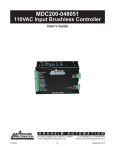
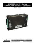
MDC151-024031 Series
24V, 3A Brushless DC Controller
User’s Guide
A N A H E I M
A U T O M A T I O N
910 East Orangefair Lane, Anaheim, CA 92801
e-mail: [email protected]
L011077
1
(714) 992-6990 fax: (714) 992-0471
website: www.anaheimautomation.com
July 2013
MDC151-024031 Driver Features
•
•
•
•
•
•
•
•
•
•
•
•
Fixed Current Limit Setting 3.0 Amps
0V to 5V External Voltage Speed Control
2-Quadrant Operation
Hall Sensor Feedback
Constant Velocity Mode
Short Circuit Protection
Requires 10 - 24VDC
Speed Out
Run/Stop, Freewheel and Direction
TTL-CMOS Compatible Inputs
Compact Size
Open Frame
General Description
The MDC151-024031 driver is designed to drive DC brushless motors at currents of up to 3A (peak)
and 24V. Using hall sensor feedback, a constant velocity mode is set. The driver is protected against
over current (cycle-by-cycle), hall sensor error and under voltage. When an error occurs, a fault light
is turned on to notify the user. An external voltage (0-5VDC) can be used to control the speed. The
direction of the motor can be preset by the direction control input. Other inputs to the drive include
a run/stop and a motor freewheel input.
Fault Protection
If a motor current level exceeding the current limit set, an over current latch is activated, shutting off
the output. This driver is equipped with a FAULT LED to alert the user of the following conditions.
1. Invalid Sensor Input Code
2. Over Current. The driver is equipped with cycle-by-cycle current limiting or over current latch.
3. Undervoltage Lockout activation at 9.1VDC for the input voltage and 4.5VDC for Hall Sensor voltage.
Power Supply/Ordering Information
Ordering Information
Part Number
MDC151-024031
MDC151-024031-TB
L011077
Description
10-24VDC, 3A Brushless Controller, Closed loop, Open-Frame
10-24VDC, 3A Brushless Controller, Closed loop, Open-Frame with detachable terminal
blocks
PS-35-24
DC Power Supply 24VDC at 1.5 Amps
PSA24V2.7A
DC Power Supply 24VDC at 2.7 Amps
CBL-AA4031
7 Pin Input Connector with 12”, 22AWG Leads
CBL-AA6131
8 Pin Motor Connector with 12”, 22AWG Leads
CON-6404407
7 Pin Connector with 0.100” Centers (Amp #640440-7)
CON-6404408
8 Pin Connector with 0.100” Centers (Amp #640440-8)
2
July 2013
Specifications
Control Inputs:(P1, Pins 3-5)
TTL-CMOS Compatible
Logic “0” = 0-0.8VDC
Logic “1” = OPEN
All three inputs (run/stop, direction, and freewheel) are pulled up to 40k ohm resistors.
Run/Stop: (P1, Pin 3)
Logic “1” (open) - Motor will not run and if running will come to a hard stop
Logic “0” - Motor will run
Direction Control: (P1, Pin 4)
Logic “1” (open) - Clockwise
Logic “0” - Counterclockwise
Freewheel: (P1, Pin 5)
Logic “1” (open) - Motor is Enabled
Logic “0” - Motor is de-energized and will coast
Vcontrol: (P1, Pin 6)
To control the speed of the motor with an external DC voltage, 0VDC (min) - 5VDC (max)
Speed Output (PGout): (P1, Pin 7)
An open drain pulse output has a max rating of 30VDC/50mA.
8-pole motor RPM = 15 * PG OUT (in Hz)
6-pole motor RPM = 20 * PG OUT (in Hz)
4-pole motor RPM = 30 * PG OUT (in Hz)
Output Current Rating:
3.0 amperes per phase maximum operating peak current
(1.5 amperes per phase maximum operating continuous current)
Power Requirements: (P1, Pins 1 and 2)
10VDC (min) - 24VDC (max)
Operating Temperature:
Board: 0°-70° C
L011077
3
July 2013
Hall Sensor Power Output:
6.25V @ 30mA maximum. Typical current draw from hall sensor is 20mA.
All three Hall Sensor inputs are pulled up through 20K ohm resistors.
Closed Loop (Constant Velocity Mode)
The driver is set for Closed Loop operation. Closed Loop operation is used for applications where
speed regulation is needed. Under closed loop operation, the speed is regulated despite changes
to the load.
If using an Anaheim Automation DC Brushless motor, the tables shown on the next page are the
Close Loop potentiometer and jumper settings for each motor. The regulated speed of the motor is
then controlled by adjusting external speed input. The motor speed can be monitored by measuring
the pulse rate of PG OUT (P1 - pin 7).
If using a non-Anaheim Automation DC Brushless Motor.
1. Start with setting the jumpers on pins 1 and 2.
2. Set CL Adjust Pot to 50%.
3. Adjust the external speed input to 5V.
4. Decrease the closed loop gain by turning the pot CCW until the motor speed decreases
to the maximum speed. If the rated speed does not change or cannot be varied, switch
the jumpers to pin 2 and 3.
Anaheim Automation Motor Closed Loop Settings
4-Pole Motors
8-Pole Motors
Motor
JP1
CL
POT
MAX SPD
(RPM)
BLWR092S-24V-4600
1-2
75%
4600
BLWR110S-15V-8000
1-2
75%
8000
BLWR111S-12V-15000
1-2
75%
15000
BLWR111S-24V-10000
1-2
75%
10000
BLWR112S-24V-3700
1-2
25%
3700
BLWR112S-36V-10000*
1-2
75%
7500
BLWR132S-24V-4000
1-2
25%
4000
BLWR231S-36V-4000*
1-2
25%
3000
BLWR231S-24V-11000
1-2
75%
11000
BLWS231S-24V-2000
2-3
75%
2000
BLWS232S-24V-1350
2-3
75%
1350
BLWS233D-24V-4000
BLWS233S-24V-4000
1-2
25%
4000
Motor
JP1
CL
POT
MAX SPD
(RPM)
BLY171S-17V-8000
1-2
75%
8000
BLY172S-17V-9500
1-2
75%
9500
BLY171S-24V-4000
1-2
75%
4000
BLY172D-24V-4000
BLY172S-24V-4000
1-2
75%
4000
BLY173D-24V-4000
BLY173S-24V-4000
1-2
75%
4000
BLY174D-24V-4000
BLY174S-24V-4000
1-2
75%
4000
BLY171S-12V-200
2-3
25%
200
BLY171S-15V-8000
1-2
75%
8000
BLY171S-17V-8000
1-2
75%
8000
BLY172D-12V-230
2-3
25%
230
BLY174D-24V-12000
1-2
75%
12000
BLY172S-12V-500
2-3
100%
500
*Note: 36V motors ran at 24VDC. Speed is set to run at 75%
of rated value.
L011077
4
July 2013
Commutation Sequence
Step
1
2
Phase A
+
Z
Phase B
Z
+
Phase C
-
-
Hall A
1
Hall B
Hall C
3
Step
4
5
6
1
2
3
-
-
Z
+
+
Z
-
-
Z
+
+
1
0
0
0
1
1
0
0
0
Phase A
-
Z
Phase B
Z
-
Z
Phase C
+
0
1
Hall A
1
0
0
1
1
1
120° Hall Spacing Sequence Forward
4
5
6
+
+
Z
-
-
Z
+
+
+
Z
-
-
Z
1
1
0
0
0
1
Hall B
0
1
1
1
0
0
Hall C
0
0
0
1
1
1
120° Hall Spacing Sequence Reverse
Step
Step
1
2
3
4
5
6
1
2
3
4
5
6
Phase A
+
Z
-
-
Z
+
Phase A
-
Z
+
+
Z
-
Phase B
Z
+
+
Z
-
Phase C
-
-
Z
+
+
-
Phase B
Z
-
-
Z
+
+
Z
Phase C
+
+
Z
-
-
Z
Hall A
1
1
1
0
0
0
Hall A
1
1
1
0
0
0
Hall B
0
1
1
1
0
0
Hall B
0
1
1
1
0
0
Hall C
0
0
1
1
1
0
Hall C
0
0
1
1
1
0
60° Hall Spacing Sequence Forward
60° Hall Spacing Sequence Reverse
+ = Top Transistor ON, Bottom Transistor OFF, Current Flows into this wire
- = Top Transistor OFF, Bottom Transistor ON, Current Flows out of this wire
Z = Top Transistor OFF, Bottom Transistor OFF, No current into or out of this wire (High Impedance)
Motor Connection
Refer to the hookup diagram for typical driver applications. When connecting a motor for the first
time, connect the hall sensor wires (5 of them) to the driver. DO NOT CONNECT THE PHASES
YET. Turn on power and rotate the motor by hand. If the RED FAULT LED comes on, the hall phases
are incorrectly wired. If the RED FAULT LED does not come on then the hall wires are connected
correctly. Power the unit down and proceed to connect the motor phases. If the motor does not run
or runs erratically, power down and check the speed potentiometer and make sure the phases are
connected correctly. There are six different ways to connect the phase wires, and normally only two
will allow the motor to rotate, but only one is correct. If the direction of the motor is changed and the
no-load current of the motor is approximately the same and the motor runs smoothly in both directions
then the phase wires are correct.
The wiring of the motor phases should be separated from the hall and input connections to not allow
a possible source of interference.
L011077
5
July 2013
Connecting to the MDC151-024031
The MDC151-024031 is designed with cost savings and size as two of the primary design criteria.
For this reason, the MTA-100 series connector was chosen for these products as a reliable small
and low cost connector. This is a common Insulation Displacement Connector (IDC) manufactured
by AMP Corporation. The inputs to the driver are on a 7-pin connector and the motors are on a
8-pin connector. These connectors are not supplied with the driver, but can be purchased from
Anaheim Automation or AMP/Tyco Electronics.
The two images below show how a hand tool can be used to quickly make the cable to connect to
the driver. This cable can be made in approximately 10 seconds per wire using the hand tool.
Tooling from AMP/Tyco Electronics
Part Number
Description
58074-1
Manual Hand Tool with Interchangeable Head (shown above)
58075-1
Air Hand Tool with Interchangeable Head
58338-1
Air Bench Mount Tool with Interchangeable Head and Foot Switch
58246-1
Die Head for Closed End MTA-100 Connectors (shown above)
Tooling from AMP/Tyco Electronics
Part Number
L011077
Description
640440-7
7 Pin MTA-100 Connector, Closed End with Lock, 22 AWG Red, Tin Plated
640440-8
8 Pin MTA-100 Connector, Closed End with Lock, 22 AWG Red, Tin Plated
640441-7
7 Pin MTA-100 Connector, Closed End with Lock, 24 AWG White, Tin Plate
640441-8
8 Pin MTA-100 Connector, Closed End with Lock, 24 AWG White, Tin Plated
640442-7
7 Pin MTA-100 Connector, Closed End with Lock, 26 AWG Blue, Tin Plated
640442-8
8 Pin MTA-100 Connector, Closed End with Lock, 26 AWG Blue, Tin Plated
6
July 2013
Terminal Descriptions
Pin #
Description
Pin #
Description
1
VIN (10-24VDC)
1
Phase A
2
GND
2
Phase B
3
Run/Stop
3
Phase C
4
Direction
4
Hall Sensor Power
5
Freewheel
5
Hall Sensor A
6
VControl
6
Hall Sensor B
7
PGout
7
Hall Sensor C
8
Hall Sensor Ground
P1: Power, Control Inputs
and Outputs
P2: Motor Hall Terminals
and Motor Phase Terminals
Motor Freewheel
The motor freewheel feature allows the de-energizing of the motor phases. A high (open) input at
this input causes the motor to run at the given speed, while a low at this input causes the motor to
coast to a stop.
Motor Run/Stop
The motor run/stop feature allows the stopping of a motor by shorting out the bottom drives of the
three phases. A low at this input allows the motor to run, while a high (open) input does not allow
motor operation and if operating causes rapid deceleration.
Motor Direction
The motor direction feature allows the changing of the rotation of the motor. This input should not be
changed while motion is in progress. A high (open) input causes the motor to turn in the CW direction, while a low at this input causes the motor to turn in the CCW direction.
Note: Avoid changing the direction of rotation when the motor is already running any
one direction.
The following instructions must be followed to prevent permanent drive failure due to over-current
conditions that exist in dynamic direction reversals of the motor:
1. Stop the motor by grounding the RUN/STOP input
2. Wait for at least 500mS
3. Change the direction with the DIRECTION input
4. Run the motor by removing ground signal on the RUN/STOP input
Speed Adjust Setting
The speed may be varied at Vcontrol from 0V-5V maximum. If a voltage other than 0V to 5V is needed
to control the speed of the motor, contact Anaheim Automation for custom tuning of the Vcontrol input.
L011077
7
July 2013
Speed Output
The PG OUT terminal (P1 - pin 7) is used to determine the speed of the motor shaft. An open drain
output is shown at a rate of 4 pulses for 1 revolution of an 8-pole motor, 3 pulses for 1 revolution of a
6-pole motor, and 2 pulses for 1 revolution of a 4-pole motor. Max rating of 30VDC/50mA.
# Poles
RPM
8
15 * PG OUT (in Hz)
6
20 * PG OUT (in Hz)
4
30 * PG OUT (in Hz)
Heating Considerations
The temperature of the board should never be allowed to rise above 70° Celsius. If necessary, air
should be blown across the heat sink to maintain suitable temperatures.
Torque Curves
BLWR132S-24V-4000 with MDC151-024031, 24VDC
4200
2
Torque-Speed
Torque-Current
4000
3600
1
Current (Amp)
RPM
3800
3400
3200
3000
0
1
2
3
4
5
6
7
0
Torque (oz-in)
L011077
8
July 2013
Typical Wiring Diagram
Dimensions
MDC151-024031TB
MDC151-024031
*All units in inches
L011077
9
July 2013
COPYRIGHT
Copyright 2013 by Anaheim Automation. All rights reserved. No part of this publication may be reproduced,
transmitted, transcribed, stored in a retrieval system, or translated into any language, in any form or by
any means, electronic, mechanical, magnetic, optical, chemical, manual, or otherwise, without the prior
written permission of Anaheim Automation, 910 E. Orangefair Lane, Anaheim, CA 92801.
DISCLAIMER
Though every effort has been made to supply complete and accurate information in this manual, the
contents are subject to change without notice or obligation to inform the buyer. In no event will Anaheim
Automation be liable for direct, indirect, special, incidental, or consequential damages arising out
of the use or inability to use the product or documentation.
Anaheim Automation’s general policy does not recommend the use of its’ products in life support applications
wherein a failure or malfunction of the product may directly threaten life or injury. Per Anaheim Automation’s
Terms and Conditions, the user of Anaheim Automation products in life support applications assumes all
risks of such use and indemnifies Anaheim Automation against all damages.
LIMITED WARRANTY
All Anaheim Automation products are warranted against defects in workmanship, materials and construction,
when used under Normal Operating Conditions and when used in accordance with specifications. This
warranty shall be in effect for a period of twelve months from the date of purchase or eighteen months
from the date of manufacture, whichever comes first. Warranty provisions may be voided if products
are subjected to physical modifications, damage, abuse, or misuse.
Anaheim Automation will repair or replace at its’ option, any product which has been found to be defective
and is within the warranty period, provided that the item is shipped freight prepaid, with previous authorization
(RMA#) to Anaheim Automation’s plant in Anaheim, California.
TECHNICAL SUPPORT
If you should require technical support or if you have problems using any of the equipment covered by this
manual, please read the manual completely to see if it will answer the questions you have. If you need
assistance beyond what this manual can provide, contact your Local Distributor where you purchased the
unit, or contact the factory direct.
ANAHEIM AUTOMATION
L011077
10
July 2013