1
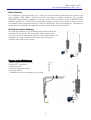
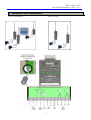
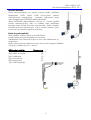
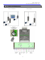
INSTALLATION INSTRUCTIONS
and
USER MANUAL
M2M i-LINK
Point-to-Point
M2M i-LINK. P-to-P.
User Manual/Käyttöohje, EN-FI, V2.1
1 TABLE OF CONTENT
1 TABLE OF CONTENT ................................................................................................................... 2
2 INSTALLING THE EQUIPMENT ...................................................................................................... 4
2.1 INSTALLATION .......................................................................................................................... 4
3 CONNECTING THE INPUTS AND OUTPUTS ................................................................................. 5
3.1 INPUT CONNECTIONS ............................................................................................................... 5
3.2 OUTPUT CONNECTIONS ............................................................................................................ 5
3.3 PULSE INPUT, P......................................................................................................................... 5
4 SETTINGS ................................................................................................................................... 6
5 CHANNEL CHANGE .................................................................................................................... 7
5.1 HOW TO CHANGE THE CHANNEL ................................................................................................. 7
5.1.1 Channel selection table .................................................................................................... 7
6 FACTORY SETTINGS .................................................................................................................... 8
7 CONNECTION EXAMPLES ........................................................................................................... 9
1 LAITTEISTON ASENNUS JA KÄYTTÖÖNOTTO ............................................................................ 12
1.1 ASENNUS .............................................................................................................................. 12
2 TULOJEN JA LÄHTÖJEN KYTKENNÄT ......................................................................................... 13
2.1 ALA-ASEMAN TILATIETOTULOT .................................................................................................. 13
2.2 TILATIETOLÄHDÖT ................................................................................................................... 13
2.3 PULSSITULO, P ....................................................................................................................... 13
3 ASETUKSET ............................................................................................................................... 14
4 KANAVANVAIHTO ..................................................................................................................... 15
4.1.1 Kanavien valintataulukko ................................................................................................ 15
5 TEHDASASETUKSET ................................................................................................................... 16
6 KYTKENTÄESIMERKKEJÄ ............................................................................................................. 17
2
M2M i-LINK. P-to-P.
User Manual/Käyttöohje, EN-FI, V2.1
Dear Customer,
This installation manual provides you in brief with all the essential information you need to get
your cordless SATEL M2M i-LINK Point-to-Point package in working condition. The cordless
SATELLINE Radio Modem enables the devices' mutual communication. These SATELLINE Radio
Modems operate on so-called license-free radio frequencies and can therefore be taken into use
immediately without separate permission from the authorities. All of the settings etc. needed for a
connection have already been adjusted so all you have to do is the final hook-up.
The Point-to-Point Package
This package enables you to cordlessly control and monitor the
operations of two points. The equipment makes sending and
receiving two status information (switch or other digital status). All
changes in the input transmits to the other device as output.
Transfer time is about one second.
Contents of the M2M Package:
2 Radio Modems with antennas
2 i-LINK I/O- converters
2 Power supplies
2 Antenna installation plates
2 Antenna cables
1 installation instruction booklet for the i-LINK
(1, 2)
(3)
(4)
(5)
(6)
3
M2M i-LINK. P-to-P.
User Manual/Käyttöohje, EN-FI, V2.1
2 INSTALLING THE EQUIPMENT
Choose the places for installation where the products may be easily mounted. If at all possible,
choose a place where there is nothing to obstruct (walls, etc.) the transmission of radio signals
'between' the devices' antennas.
2.1 Installation
1.
2.
3.
4.
Connect the antenna cable (6) to Installation plate (5).
Connect the antenna (1) to the installation plate.
Connect the antenna cable to the radio modem (2).
Connect the power supply (4) to the i-LINK screw
couplings 9-30VDC. Connect the power supply's black
wire to the negative pole (-) and the red wire to the
positive pole (+).
5. Connect the i-LINK to the Radio Modem so that it is
locked.
Make these connections to the other equipment as well.
Note! The antennas can also be connected directly to the
radio modems without the cable and installation plate, if
needed.
The devices should now work together.
4
M2M i-LINK. P-to-P.
User Manual/Käyttöohje, EN-FI, V2.1
3 CONNECTING THE INPUTS AND OUTPUTS
Once you have installed the M2M package, all you need to do is just connect the actual inputs
and outputs.
Changes in the Outputs occurs when the corresponding Inputs, for example D1, of the one
device changes from 0 to +12V, or vice versa, whereupon the contact of the output's 2 internal
relay connects or opens. These contacts allow you to perform the desired function by using them
to connect plus or minus to the desired device. The contact points can be used to control a 1224VDC device at a 1 Ampere maximum current.
3.1 Input connections
Connect the transmitting device to any Digital input, so that
you get a status change in the input, i.e. +12V 'ON or OFF'.
You can take the Plus Voltage from the + - screw or from the
separate + - output.
3.2 Output connections
Connect the corresponding output of receiving i-LINK to the
device you want to control. The state of the output relay
changes according to the corresponding change of the input
on the other i-LINK. The relay contacts and changes are
independent from each other.
D1, D2=Digital outputs
Outputs
3.3 Pulse input, P
Not in use.
When the inputs and outputs are connected, the system is ready to work and you may connect the
power supply to the wall socket.
For more information concerning the functions of the i-LINK, see the i-LINK User Manual.
5
M2M i-LINK. P-to-P.
User Manual/Käyttöohje, EN-FI, V2.1
4 SETTINGS
If you are using the i-LINK M2M-package the settings are in this chapter are already done and the
chapter can be skipped.
SETTINGS OF THE SATELLINE-1870 RADIO MODEM AND i-LINK:
o The radio modem settings are: 9600kbps, "N-8-1".
o M/P-switch is in P-position.
o Before connecting the device to a power supply, connect first all inputs and outputs that are
to be used.
o When both units have these basic settings the supply voltage can be connected.
o Check that the channel switches 2, 3, 4, 5 = 0000, unless they are purposely selected for
a specific channel for example 2, 3, 4, 5= 0101= channel 5 (see channel selection table).
6
M2M i-LINK. P-to-P.
User Manual/Käyttöohje, EN-FI, V2.1
5 CHANNEL CHANGE
The radio modems of the M2M-package operate on the European license free frequency band.
This band has several different channels. Sometimes it may happen that few systems use the same
channel. If this occurs, the system stability may change and behave in an uncertain manner.
However, if this happens, it is possible to change the radio modems to another channel.
The standard M2M sales package is pre-set to a specific channel and changes are not needed in
order to start the normal operation. The changes are needed only, if the system doesn’t work
properly.
5.1
How to change the channel
The i-LINK reads the channel information from the CHANNEL switches 1-2-4-8 when the power is
turned ON. In default mode the channel setting is 0-0-0-0.
The channel can be changed by turning first the power OFF and then by setting the ADDRESS
switches (channel selector) to other position for example 1-0-0-0.
1=up / 0=down.
5.1.1 Channel selection table
DIP 2 3 4 5
0 0 0 0= channel selection disabled
0 0 1 0= channel 2
0 1 0 0= channel 4
0 1 1 0= channel 6
1 0 0 0= channel 8
1 0 1 0= channel10
DIP 2 3 4 5
0 0 0 1= channel 1
0 0 1 1= channel 3
0 1 0 1= channel 5
0 1 1 1= channel 7
1 0 0 1= channel 9
The channel must be the same for both i-LINK units before turning power ON.
When the power is ON the operation channel has changed.
NOTE1! 0000=disable.
NOTE2! The i-LINK unit will not operate with the settings 1011, 1100, 1101, 1110 or 1111. The
power ON indicator starts to blink in case any of these settings has been chosen.
7
M2M i-LINK. P-to-P.
User Manual/Käyttöohje, EN-FI, V2.1
6 FACTORY SETTINGS
The i-LINK I/O -converter is shipped with the following default settings (unless specifically ordered
with settings other than those listed below):
M2M Point-to-Point
FIXED SETTINGS DEFINED AT THE TIME OF ORDER
PM, protocol switch, P-to-P or Multipoint, DIP 1.
ADDRESS/CHANNEL. DIP 2, 3, 4, 5.
Transmission cycle. DIP 6
DE, Alarm delay. DIP 7.
SM, Safe mode. DIP 8.
0
0000
0
0
0
M2M Point-to-Multipoint
ASETUKSET
PRTCL, protokolla. DIP 1
ADDRESS, osoite. DIP 1, 2, 3, 4, 5, 6.
P-to-MP
1000000
8
= Point-to-Point
= No address
= 1/sec (European std.)
= No Delay
= No Safe Mode
=Point-to-Multipoint
ja 0100000
M2M i-LINK. P-to-P.
User Manual/Käyttöohje, EN-FI, V2.1
7 CONNECTION EXAMPLES
Point-to-Multipoint
Point-to-Point
9
M2M i-LINK. P-to-P.
User Manual/Käyttöohje, EN-FI, V2.1
ASENNUSja
KÄYTTÖOHJE
M2M i-LINK
Point-to-Point
10
M2M i-LINK. P-to-P.
User Manual/Käyttöohje, EN-FI, V2.1
Arvoisa asiakas,
Tässä asennusohjeessa on lyhyesti kerrottu kaikki oleellinen
langattoman SATEL M2M i-LINK Point-to-Point paketin
toimintakuntoon saattamiseksi.
Laitteiden keskinäinen yhteys
toimii langattomasti SATELLINE radiomodeemeilla.
Nämä SATELLINE radiomodeemit toimivat ns. luvasta vapailla
olevilla radiotaajuuksilla, joten ne voidaan ottaa välittömästi
käyttöön ilman erillistä ilmoitusta viranomaisille. Kaikki yhteyden
kannalta tarvittavat asetukset yms. ovat jo valmiiksi asetetut, joten
sinulle jää vain laitteiston lopullinen kytkentä.
Point-to-point paketti
Tällä paketilla voidaan ohjata ja seurata kahden
pisteen välistä toimintaa langattomasti. Laitteisto
mahdollistaa 2 kpl tilatietojen (kytkin tai muu tieto) lähettämisen ja
vastaanoton.
Kaikki tuloissa (Inputs) tapahtuva muutos siirtyy toisen laiteparin lähdöiksi
(Outputs). Siirtoaika on noin 1 sekunti.
M2M-paketin sisältö:
Kuvanumero
2kpl radiomodeemeja antenneineen
(1ja 2)
2kpl i-LINK muuntimia
(3)
2kpl virtalähteitä
(4)
2kpl antennialusta
(5)
2kpl antennijohto
(6)
1kpl i-LINK käyttöohje
11
M2M i-LINK. P-to-P.
User Manual/Käyttöohje, EN-FI, V2.1
1 LAITTEISTON ASENNUS JA KÄYTTÖÖNOTTO
Valitse asennuspaikat siten, että tuotteet voidaan helposti kiinnittää. Mikäli mahdollista,
molempien laitteiden paikka olisi hyvä valita niin, että niiden antennien ”väliin” jää
mahdollisimman vähän radiosignaaleille haitallisia esteitä, kuten esimerkiksi seiniä tms.
1.1 Asennus
1.
2.
3.
4.
Kiinnitä antennijohto (6) asennuslevyyn (5).
Kiinnitä antenni (1) asennuslevyyn.
Kiinnitä antennijohdon toinen pää radiomodeemiin (2).
Kytke virtalähde (4) i-LINK:in ruuviliitimiin 9-30VDC,
siten, että virtalähteen musta johto tulee miinus-napaan
(-) ja punaisella suojalla oleva johto tulee plus-napaan
(+).
5. Kiinnitä iLINK (3)radiomodeemiin siten, että
radiomodeemin liittimet naksahtavat paikoilleen kuvan
osoitamalla tavalla.
Huom. Antennit voidaan asentaa myös
suoraan radiomodeemeihin ilman
asennuslevyä ja antennijohtoa.
Tee nämä samat kytkennät myös toiselle
laitteistolle.
Asennuksen jälkeen laitteet ovat
keskenään toimintakunnossa.
Jäljellä on enää tulojen/lähtöjen
kytkennät.
12
M2M i-LINK. P-to-P.
User Manual/Käyttöohje, EN-FI, V2.1
2 TULOJEN JA LÄHTÖJEN KYTKENNÄT
Kun asennus on suoritettu, jää jäljelle enää varsinainen tulojen ja lähtöjen kytkentä.
2.1
Ala-aseman tilatietotulot
Ala-aseman tulon (D1-D2) tilatieto muuttuu kun sen jännite muuttuu 0V -> +12/24VDC tai
+12/24VDC -> 0V. Plus-jännitteen voi ottaa esim. i-LINK:in +-ruuvista tai sen vieressä
olevasta erillisestä +-lähdöstä.
2.2
Tilatietolähdöt
Lähtöjä ohjataan toisen i-LINK:in tuloissa tapahtuvilla
muutoksilla. Muutoksen perusteella lähdön rele vetää tai
päästää. Releet ovat normaalisti avoinna. Kärjet ovat
keskenään riippumattomia, joten niiden kautta voidaan
ohjata toisistaan riippumattomia toimintoja.
D1,D2=Tilatietotulot
2.3
Outputs =Tilatietolähdöt
Pulssitulo, P
Ei ole käytössä Point-to-Point muodossa. Pulssitulo toimii ainoastaan iLINK PC ohjelmalla.
Kun tulot ja lähdöt on kytketty, voit kytkeä virtalähde pistorasiaan ja laite
on valmis toimintaan.
Jos tarvitset lisätietoa i-LINK:in toiminnoista, tutustu myös M2M-paketissa
olevaan i-LINK -käyttöohjeeseen.
13
M2M i-LINK. P-to-P.
User Manual/Käyttöohje, EN-FI, V2.1
3 ASETUKSET
HUOM!
Mikäli käytössäsi on SATEL M2M MINI -paketti, kohdan ”ASETUKSET” on jo valmiiksi tehty, joten
jatkon läpi käyminen ei ole välttämätöntä.
SATELLINE-1870 RADIOMOODEMIN ja i-LINK:in ASETUKSIA:
SIIRTONOPEUS, BAUD RATE
Aseta SATELLINE radiomodeemille siirtonopeus 9600. Tarkista, että muut parametrit ovat: “N-81”.
PROTOKOLLA, PRTCL
Aseta i-LINK:in PRTCL-kytkin asentoon P (Point-to-Point).
KYTKENNÄT
Varmistaaksesi i-LINK:in häiriöttömän toiminnan, yhdistä kaikki tulot ja lähdöt ennen virran
kytkemistä. Kytkennöistä lisää tämän ohjeen lopussa.
14
M2M i-LINK. P-to-P.
User Manual/Käyttöohje, EN-FI, V2.1
4 KANAVANVAIHTO
i-LINK on mahdollista ohjelmoida 10 eri kanavalle. Laiteparin käyttö/vaihto eri kanavalle on
suositeltavaa, mikäli käytettävä kanava on häiriöllinen, esim. muita i-LINK:ejä samalla kanavalla
tms.
Tehdasasetuksena kanavakytkimet ovat asennossa 0000 000.
2, 3, 4, 5 CHANNEL (kanava)
Kun i-LINK:iin kytketään virrat päälle se lukee DIP-kytkimien tiedot ja toimii niiden asetusten
mukaan. Alkuasetus on 0-0-0-0. 1=ylös / 0=alas.
Kanava vaihdetaan sammuttamalla laitteesta virta, valitsemalla kanava ja kytkemällä virrat
uudelleen päälle.
4.1.1 Kanavien valintataulukko
DIP 2 3 4 5
0 0 0 0= kanavan valinta ei ole käytössä
0 0 1 0= kanava 2
0 1 0 0= kanava 4
0 1 1 0= kanava 6
1 0 0 0= kanava 8
1 0 1 0= kanava10
DIP 2 3 4 5
0 0 0 1= kanava 1
0 0 1 1= kanava 3
0 1 0 1= kanava 5
0 1 1 1= kanava 7
1 0 0 1= kanava 9
Huomautus 1
Tarkista, että molemmat i-LINK:it ovat samalla kanavalla.
Huomautus 2
i-LINK ei toimi seuraavilla kanava-asetuksilla:
1011, 1100, 1101, 1110 tai 1111. Mikäli jokin näistä kanavista on valittu, virtaledi vilkkuu eikä
laite toimi. Vaihda tällöin uusi kanava yllä olevan taulukon mukaan.
15
M2M i-LINK. P-to-P.
User Manual/Käyttöohje, EN-FI, V2.1
5 TEHDASASETUKSET
Tehdasasetukset
i-LINK I/O- konvertteri toimitetaan seuraavilla tehdasasetuksilla, ellei toisin ole määritelty:
M2M Point-to-Point
OLETUSASETUKSET
1. PM, protokolla -kytkin
2, 3, 4, 5 ADDRESS/CHANNEL, osoite / kanava
7. DE, turvatilan ja hälytyksen viive
8. SM, turvatilan asetus
M2M Point-to-Multipoint
ASETUKSET
PRTCL, protokolla
ADDRESS, osoite
0= P-to-P
0000
0
0
P-to-MP
1000000
16
= Poin-to-point
= ei kanavaa
= ei viivettä
= ei turvatilaa
=Point-to-Multipoint
ja 0100000
M2M i-LINK. P-to-P.
User Manual/Käyttöohje, EN-FI, V2.1
6
KYTKENTÄESIMERKKEJÄ
Point-to-Multipoint
Point-to-Point
17
M2M i-LINK. P-to-P.
User Manual/Käyttöohje, EN-FI, V2.1
SATEL Oy
P.O.Box 142, FIN-24101 SALO, Finland
Street: Meriniitynkatu 17, FIN-24100 SALO, Finland
Tel +358 2 777 7800, Fax +358 2 777 7810, E-mail [email protected]
www.satel.com
18