1
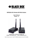
MDR221A Wireless V.90 RS232 Modem
User’s Manual
Version 1.0
1000 Park Drive – Lawrence, PA 15055-1018 – (724)746-5500
Web site: www.blackbox.com
E-mail: [email protected]
Order Toll Free in the US: Call 877-877-BBOX ( Outside the US call 724-746-5500)
Document & FCC Information
Copyright
Information
Copyright © 2004 Black Box All rights reserved.The
information contained in this manual and the accompanying
software programs are copyrighted and all rights are reserved
by Black Box, Black Box, reserves the right to
make periodic modifications of this product without obligation
to notify any person or entity of such revision.
Copying, duplicating, selling, or otherwise distributing any part
of this product without the prior consent of an authorized
representative of Black Box is prohibited. All brands and
product names in this publication are registered trademarks or
trademarks of their respective holders.
FCC Notice
Warning: This device complies with Part 15 of the FCC Rules. Operation is subject to
the following two conditions: (1) This device may not cause harmful
interference and (2) This device must accept any interference received,
including interference that may cause undesired operation.
RF Exposure/Installation Instructions
Warning: To satisfy FCC RF exposure requirements for mobile transmitting devices,
this equipment must be professionally installed such that the end user is
prevented from replacing the antenna with a nonapproved antenna. The end
user should also be prevented from being within 20cm of the antenna during
normal use with the exception of hands, feet and ankles.
Caution: Any change or modification not expressly approved by Black Box
could void the user’s authority to operate the equipment.
The preceding statement must be included as a CAUTION statement in
manuals for OEM products to alert users on FCC RF Exposure compliance.
2
Table of Contents
Users Manual……………………………….………
1
1. Overview………………………………………..……
4
2. Flow Control……………….……………….…..……
4
3. MDR221A Definitions…………..….….……..….…
4
3.1 Cable Pinout Definitions…………………………………
5
3.2 MRD221A Configuration Utility Software………………
5
3.2.1 Installation……………………………………
5
3.2.2 Software Definitions…………………………
6
3.2.3 Computer Settings Window………………..
9
4. Programming…………..….….……..….…………..
4.1 Changing MDR221A Settings…………………………..
5. Troubleshooting……………………………………
9
10
11
Figures
Figure 1
Multiple Networks of MDR221A units………………….
4
3
MDR221A User's Manual
1) Overview
The MDR221A product provides a wireless RS232 connection between
different devices. Each MDR221A unit can be programmed as a Server or a
Client, allowing for the creation of a two device or multiple device wireless
network. In addition, multiple networks can be created by programming each
network of MDR221A units with unique Channel Number and System ID
combinations. See Figure 1 below. To create a wireless network, simply
program one of the units as a Server and the other units as Clients.
Figure 1 - Multiple Networks Of MDR221A Units
Example: Channel Number = 13
System ID = 001002003004005006007008
Example: Channel Number = 25
System ID = 012023034045056067078089
2) Flow Control
For optimal performance, Hardware Flow Control is strongly recommended. If the
Clear To Send (CTS) line is not used, there is a chance that the transmit buffer
will fill up to its maximum limit and data will be lost. Whenever CTS is High, the
MDR221A is not ready to receive additional data from its host. When CTS is
Low, the ConnexLink is ready to receive data.
3) MDR221A Definitions
1) Pwr: Red LED indicates power is connected to the unit.
2) Link: Green LED indicates the units are in range of one another.
3) Rx: Red LED indicates a unit is receiving data.
4) Tx: Green LED indicates a unit is sending data.
4
MDR221A User's Manual
3.1 Cable Pinout Definitions
Standard RS232 DB9 Female Connector
(Black DB9 Female/Female Cable)
Pin
1
2
3
4
5
6
7
8
9
Description
DCD
RxD
TxD
DTR
GND
DSR
RTS
CTS
RI
Null Modem RS232 DB9 Male Connector
(Gray DB9 Female/Male Cable)
Pin
NC
2
3
4
5
6
7
8
NC
Description
DCD
TxD
RxD
DSR
GND
DTR
CTS
RTS
RI
3.2 MDR221A Configuration Utility Software
The software CD included with your MDR221A units provides a utility
for changing the settings on each unit. The software is compatible with
Microsoft® Windows 95, 98, 2000, Me, NT and XP.
3.2.1 Installation
Double-Click the MDR221A software zip file. The software will
automatically extract. It is recommended that the default location
be used when loading the software.
5
MDR221A User's Manual
3.2.2 Software Definitions
1) Client/Server: Designates MDR221A type. In each network, there must be
only one Server. All other MDR221A units must be programmed as Clients.
The number of Clients in the network is not limited; however, if performance
diminishes, consider additional RF Networks.
2) Baud Rate: This defines the serial baud rate between the MDR221A unit
and the host device, such as a PC. The RF transmission rate is fixed.
Default baud rate setting is 57600 unless the units have been pre-configured
by Black Box. The Baud Rate setting of the MDR221A must match the
Baud Rate setting of its host device.
3) Maximum Transmit Attempts: For Point-to-Point networks only. This
value represents the maximum number of times a data packet can be sent
by the MDR221A units. The default value is 16 attempts. If communication is
lost and the Client’s Link LED is on, try increasing this value in small
increments until communication is reestablished. The valid range of values
for this field is 1 to 255.
4) Broadcast Attempts: For Point-to-Multipoint networks only. This value
represents the number of times a data packet will be sent by the Server
MDR221A unit. The default value is 4 attempts. If communication is
lost and the Clients’ Link LED is on, try increasing this value in small
increments until communication is reestablished. The valid range of values
for this field is 1 to 255.
5) Channel Number: A number that designates an independent network of
MDR221A units. Up to 77 independent networks can created. The valid
range of values for this field is 0 to 76.
6
MDR221A User's Manual
6) Packet Length: Defines the fixed length or size of data packet to be
transmitted. Any packets larger than the Packet Length will be parsed and
sent consecutively by a MDR221A. For example, if the Packet Length
is 128 bytes and the Host sends 150 bytes, a MDRA221A will send 128 bytes
and then 22 bytes after the Interface Timeout expires. Any packets
smaller than the Packet Length will be transmitted once the
Interface Timeout has expired.
The Host can send variable-sized data packets, all of which are equal to or
smaller than the Packet Length. A MDR221A will wait until the Interface
Timeout expires or until the Packet Length size is reached. Therefore, if
multiple packets and/or portions of packets are sent before the Interface
Timeout expires, the receiving MDR221A Host must be able to process the
multiple packets and/or portions of packets.
Packets will be transmitted over the RF interface when one of the following
conditions occurs:
1) The number of data bytes received over the serial interface is
equal to the Packet Length, the maximum packet length is
2047 bytes.
2) A byte gap larger than the Interface Timeout occurs.
Interface Timeout
0
1
2 - 255
64
128
192
Time in Milliseconds
6.5
Invalid
Value x 0.9ms
21
137
235
IMPORTANT NOTE: The MDR221A cannot accept a fixed Packet
Length of less than 6 Bytes. If the Packet Length is set lower than
6 Bytes, the MDR221A cannot be reconfigured.
7) Interface Timeout: This parameter specifies the amount of time
between bytes that a MDR221A will wait before transmitting the data
packet. This setting is automatically calculated by the configuration
software based on the Baud Rate setting, but can be modified by the
user for optimization purposes.
IMPORTANT NOTE: When configuring units with baud rates lower than
9600kbps it is important that the Interface Timeout is not set to a value lower
than 3. It is strongly recommended that the default Interface Timeout be
used. The default values are automatically calculated based of the unit’s
Baud Rate setting.
7
MDR221A User's Manual
8) System Identification: A sequence of eight numbers that provide
added security to each independent network of MDR221A units. The
System ID is used in conjunction with the Channel Number and serves
as a password to maintain secure transfers of data. The combination
of the Channel Number and System ID must be unique to each
network of MDR221As to establish communication. Here are some
examples:
Network A: Channel Number – 13,
System ID – 001 002 003 004 005 006 007 008
Network B: Channel Number – 25,
System ID – 012 023 034 045 056 067 078 089
Multiple Servers in the same coverage area must be programmed with
different Channel Numbers to prevent inoperability of the networks.
The System ID will not prevent inoperability that occurs from locating
multiple Servers with the same Channel Number in the same coverage
area. The valid range of values for each of the eight numbers is 0 to
255.
Important Note: Separate Collocated MDR221A networks must
operate on different Channel Numbers. All units in a given
MDR221A network must have identical Channel Numbers and
System IDs.
9) Destination Address: The MAC Address of the opposite MDR221A unit in
a point to point application. Used to optimize point to point communications
by utilizing RF Acknowledgement.
10) Parity: Considered 9-Bit mode. Needs to be enabled if host requires even or
odd parity and 8 data bits. The Link LED will be deactivated when Parity is
enabled.
11) RTS: Enables the Request to Send control line.
12) Modem Control: Enables DCD, DTR, DSR and Ring Indicator control lines.
13) Firmware Version: Displays the MDR221A’s firmware version.
14) MAC Address: A unique 6 Byte, IEEE 802.3 Ethernet address assigned
by Black Box to each MDR221A. The user must not change this
information.
8
MDR221A User's Manual
3.2.3 Computer Settings Window
1) Port: Serial communications port connected to the MDR221A unit.
2) Baud Rate: Must equal the baud rate setting of the MDR221A unit that
is about to be programmed.
3) System Config: Type of MDR221A network to be configured. Valid
choices are Point-to-Point (one Server and one Client) or Point-to-Multipoint
(one Server and multiple Clients).
4) Parity: Must be checked when trying to Read or Reprogram a MDR221A
with the Parity option enabled.
4) Programming
Programming is accomplished with the following procedure:
1) Connect an MDR221A unit to a serial communications port on your computer.
2) Connect the power supply to the MDR221A unit. Make sure the Pwr LED
is on.
3) Start the MDR221A Configuration Utility.
4) Select Settings to display the Computer Settings window.
A) Select the COM Port that is connected to the MDR221A unit.
B) Select the baud rate of the MDR221A unit. All MDR221A units
are shipped with a default baud rate of 115200. If the baud rate of the
MDR221A unit is changed as described below in Section 4.1
Changing MDR221A Settings, then this setting must be set to the
same baud rate to allow proper programming of the units.
9
MDR221A User's Manual
C) Select the system configuration for the MDR221A network,
Point-to-Point (one Server and one Client) or Point-to-Multipoint
(one Server and multiple Clients).
5) Select OK.
4.1 Changing MDR221A Settings
Changing the MDR221A settings is accomplished with the following procedure:
1) Select Read Radio to display the current settings of the MDR221A unit.
2) Change desired settings.
3) After all changes have been made, select Write Radio to save the changes.
4) Cycle Power to the unit after all changes have been saved. This will set
the MDR221A unit to its normal mode of operation.
10
MDR221A User's Manual
5) Troubleshooting
Problem
Read Radio displays error message:
“Radio not responding.”
Solution
1. Make sure the proper settings are set in
the Settings Window.
See Section 4 Programming.
2. If any other programs that utilize the same
COM port as the MDR221A unit are open,
close them and try to read the radio again.
3. Reset the radio by cycling power after each
unsuccessful Read.
Write Radio displays error message:
“Radio not responding.”
1. Cycle power to the radio.
2. Read the radio and make desired changes.
See Section 4 Programming.
Client’s Link LED does not come on.
1. Make sure Server MDR221A unit is
connected to power.
2. Cycle power to the radio.
3. If Parity is enabled on unit configuration,
the Link LED will not turn on.
Link LED is on, but data does not get
transmitted or received.
1. Make sure the MDR221A unit(s) is
connected to the correct COM Port.
2. Check the COM port settings for correct
Baud Rate, Parity and either Hardware or
No Flow Control. Units can have transmission
errors with Flow Control set to Xon/Xoff.
3. Try increasing the Maximum
Transmit Attempts (for Clients) and/or
Broadcast Attempts (for Servers) values in
small increments until communication is
established.
4. Connect a Null Modem adapter between
the Client and its host device.
11