1
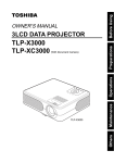
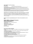
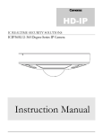
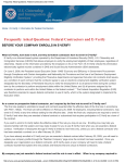
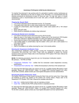
Communication Add-on
Modbus - RTU
Addendum A
Modbus - RTU Addendum A
page 2
rev 1.02
COPYRIGHT © 2008 ARCUS, ALL RIGHTS RESERVED
First edition, October 2008
ARCUS TECHNOLOGY copyrights this document. You may not
reproduce or translate into any language in any form and means any part of
this publication without the written permission from ARCUS.
ARCUS makes no representations or warranties regarding the content of this
document. We reserve the right to revise this document any time without
notice and obligation.
Revision History:
1.00 – 1st Release
1.01 – Added RSM
1.02 – Updated bookmarks
Modbus - RTU Addendum A
page 3
rev 1.02
Table of Contents
1. Introduction ..................................................................................................................... 5
2. Communication Settings ................................................................................................. 6
Baud Rate ........................................................................................................................ 6
Modbus Device Number ................................................................................................. 6
RS-485 Communication Mode ....................................................................................... 6
3. Sample Usage.................................................................................................................. 8
Achieving functionality via variables ............................................................................. 8
Standalone Example Program 1 ...................................................................................... 8
4. Modbus RTU Addressing ............................................................................................... 9
Data Model...................................................................................................................... 9
Holding Registers – Read/Write – 16 bits ...................................................................... 9
Dealing with the Swapped-Long Registers................................................................... 11
4. Modbus GUI ................................................................................................................. 12
Connection Configuration ............................................................................................. 13
Main Screen .................................................................................................................. 13
Modbus - RTU Addendum A
page 4
rev 1.02
1. Introduction
The Modbus-RTU protocol runs over the RS-485 communication medium. For tips
regarding setting up a RS-485 network, see the user manual specific to your controller.
The Arcus implementation of Modbus-RTU supports the holding register data type only.
Coils, Discrete Inputs and Input Registers are not supported.
Modbus - RTU Addendum A
page 5
rev 1.02
2. Communication Settings
Baud Rate
The RS-485 baud rate can be changed using the DB command.
Please note that the device baud rate must be within the range [1, 5].
Device Baud Value
1
2
3
4
5
Baud Rate (bps)
9600
19200
38400
57600
115200
To write the values to the device’s flash memory, use the STORE command. After a
complete power cycle, the new baud rate will be written to memory. Note that before a
power cycle is completed, the settings will not take effect.
By default:
Baud rate is set to: 1 (9600 bps)
This setting can be made either through RS-485 ASCII or USB communication
depending on your controller.
Modbus Device Number
Arcus Modbus controllers allow the user to set the Modbus device number (used for
addressing) from the range of [1-127]. In order to make this change, use the DNM
command.
To write the values to the device’s flash memory, use the STORE command. After a
complete power cycle, the new device number will be written to memory. Note that
before a power cycle is completed, the settings will not take effect.
By default:
Modbus device number is set to 1
This setting can be made either through RS-485 ASCII or USB communication
depending on your controller.
RS-485 Communication Mode
Changing from RS-485 to Modbus
By default, Arcus controllers are configuring for ASCII protocol when using RS-485
communication. In order to enable Modbus-RTU communication, set RSM=1.
Modbus - RTU Addendum A
page 6
rev 1.02
To write the values to the device’s flash memory, use the STORE command. After a
complete power cycle, the communication mode setting will be written to memory. Note
that before a power cycle is completed, the settings will not take effect.
This setting must be made through RS-485 ASCII.
Below is a table of the ASCII commands that are mentioned above. To see a complete
list of all ASCII commands, see the user manual specific to your controller.
Command
DB
Description
Return the current baud rate of the device
DB=[1,2,3,4,5]
DNM
DNM=[1-127]
RSM
Set the baud rate of the device
Get Modbus device number
Set Modbus device number
Get RS-485 Communication mode
Return
1 – 9600 bps
2 – 19200 bps
3 – 38400 bps
4 – 57600 bps
5 – 115200 bps
OK
[1-127]
OK
0 – ASCII
RSM=[0,1]
STORE
Set RS-485 Communication mode
Store settings to flash
OK
OK
1 – Modbus-RTU
Changing from Modbus to RS-485
Once your controller is in Modbus communication, it can no longer accept ASCII
commands. In order to change communication back to ASCII, you must write the value
1 into register V30. After writing to register V30, a power cycle must be performed
before the setting takes effect. Note that the setting is automatically stored to flash when
written.
See “Modbus RTU Addressing” for details on how to write the value.
Modbus - RTU Addendum A
page 7
rev 1.02
3. Sample Usage
Achieving functionality via variables
Only the general purpose variables V1-V30 of the controller are accessible via ModbusRTU communication. By reading/updating these variables, the desired functionality can
be achieved by referencing them within a running stand-alone program. For details
regarding stand-alone programming, see the user manual specific to your controller.
In a typical application, the controller runs a stand-alone program while the Modbus
master accesses variables over the Modbus-RTU protocol.
The following is a sample of such a stand-alone program.
Standalone Example Program 1
EO=1
;* Enable the motor power
WHILE 1=1
GOSUB 1
IF V1=1
X1000
WAITX
ELSEIF V1=2
X3000
WAITX
ELSEIF V1=3
X0
WAITX
ENDIF
;* Forever loop
;* Set speed settings
V2 = PX
ENDWHILE
;* If V1 is set to 1 then go to position 1000
;* Wait for move to complete
;* If V1 is set to 2 then go to position 3000
;* Wait for move to complete
;* If V1 is set to 3 then go to position 0
;* Wait for move to complete
;* Store pulse position in V2
;* Go back to WHILE statement
END
SUB 1
HSPD=V4
LSPD=V5
ACC=V6
END SUB
Modbus - RTU Addendum A
;* Set the high speed to V4 pulses/sec
;* Set the low speed to V5 pulses/sec
;* Set the acceleration to V6 msec
page 8
rev 1.02
4. Modbus RTU Addressing
The Arcus implementation of Modbus-RTU supports the holding register data type only.
Coils, Discrete Inputs and Input Registers are not supported.
Data Model
Data Type
Parameter
03h
Size
(Bits)
16
Data Type
Description
Holding Registers
Access
Address Range
Read/Write
[1-60]
Holding Registers – Read/Write – 16 bits
Address
1
2
3
4
5
6
7
8
9
10
11
12
13
14
15
16
17
18
19
20
21
22
23
24
25
26
27
Name
V1_H
V1_L
V2_H
V2_L
V3_H
V3_L
V4_H
V4_L
V5_H
V5_L
V6_H
V6_L
V7_H
V7_L
V8_H
V8_L
V9_H
V9_L
V10_H
V10_L
V11_H
V11_L
V12_H
V12_L
V13_H
V13_L
V14_H
Modbus - RTU Addendum A
Description
V1 Higher 16 bits [31:16]
V1 Lower 16 bits [15:0]
V2 Higher 16 bits [31:16]
V2 Lower 16 bits [15:0]
V3 Higher 16 bits [31:16]
V3 Lower 16 bits [15:0]
V4 Higher 16 bits [31:16]
V4 Lower 16 bits [15:0]
V5 Higher 16 bits [31:16]
V5 Lower 16 bits [15:0]
V6 Higher 16 bits [31:16]
V6 Lower 16 bits [15:0]
V7 Higher 16 bits [31:16]
V7 Lower 16 bits [15:0]
V8 Higher 16 bits [31:16]
V8 Lower 16 bits [15:0]
V9 Higher 16 bits [31:16]
V9 Lower 16 bits [15:0]
V10 Higher 16 bits [31:16]
V10 Lower 16 bits [15:0]
V11 Higher 16 bits [31:16]
V11 Lower 16 bits [15:0]
V12 Higher 16 bits [31:16]
V12 Lower 16 bits [15:0]
V13 Higher 16 bits [31:16]
V13 Lower 16 bits [15:0]
V14 Higher 16 bits [31:16]
page 9
rev 1.02
28
29
30
31
32
33
34
35
36
37
38
39
40
41
42
43
44
45
46
47
48
49
50
51
52
53
54
55
56
57
58
†59
†60
V14_L
V15_H
V15_L
V16_H
V16_L
V17_H
V17_L
V18_H
V18_L
V19_H
V19_L
V20_H
V20_L
V21_H
V21_L
V22_H
V22_L
V23_H
V23_L
V24_H
V24_L
V25_H
V25_L
V26_H
V26_L
V27_H
V27_L
V28_H
V28_L
V29_H
V29_L
V30_H
V30_L
V14 Lower 16 bits [15:0]
V15 Higher 16 bits [31:16]
V15 Lower 16 bits [15:0]
V16 Higher 16 bits [31:16]
V16 Lower 16 bits [15:0]
V17 Higher 16 bits [31:16]
V17 Lower 16 bits [15:0]
V18 Higher 16 bits [31:16]
V18 Lower 16 bits [15:0]
V19 Higher 16 bits [31:16]
V19 Lower 16 bits [15:0]
V20 Higher 16 bits [31:16]
V20 Lower 16 bits [15:0]
V21 Higher 16 bits [31:16]
V21 Lower 16 bits [15:0]
V22 Higher 16 bits [31:16]
V22 Lower 16 bits [15:0]
V23 Higher 16 bits [31:16]
V23 Lower 16 bits [15:0]
V24 Higher 16 bits [31:16]
V24 Lower 16 bits [15:0]
V25 Higher 16 bits [31:16]
V25 Lower 16 bits [15:0]
V26 Higher 16 bits [31:16]
V26 Lower 16 bits [15:0]
V27 Higher 16 bits [31:16]
V27 Lower 16 bits [15:0]
V28 Higher 16 bits [31:16]
V28 Lower 16 bits [15:0]
V29 Higher 16 bits [31:16]
V29 Lower 16 bits [15:0]
V30 Higher 16 bits [31:16]
V30 Lower 16 bits [15:0]
†V30 is reserved for communication mode setting. In order to change from Modbus
communication to ASCII, set V30=1.
Modbus - RTU Addendum A
page 10
rev 1.02
Dealing with the Swapped-Long Registers
Variables V1-V30 are 32-bit twos-complement numbers. Since standard Modbus
holding registers only hold 16 bits, the full 32-bit numbers are stored into two different
registers. The lower addressed register represents the higher 16 bits of the 32-bit number,
while higher addressed register represents the lower 16 bits of the 32-bit number. This is
known as swapped-long.
Example 1: Set V1 to: -34930493 (0xFDEB00C3)
V1 holding register is found at address 1.
Set Holding Register Address 1 [bits 16:31] to 0xFDEB
Set Holding Register Address 2 [bits 0:15] to 0x00C3
Example 2: Read V2 register
V2 holding register is found
Assuming that the values stored in these registers are:
Holding Register Address 3 [bits 16:31] = 0x0000
Holding Register Address 4 [bits 0:15] = 0x4933
When reading this value, the full 32-bit value is: +18739 (0x00004933)
Modbus - RTU Addendum A
page 11
rev 1.02
4. Modbus GUI
Arcus provides a GUI that allows Modbus communication to be achieved between a PC
and the controller. Visit our website to download this software.
www.arcus-technology.com
Before running the program, make sure to register the 3rd party Modbus master driver on
your PC. See instructions below:
a. Download and extract GUI folder onto your PC.
b. Using the command line, browse to the “mod102” directory within the GUI folder
and type “mbserver.exe /regserver” and press enter.
c. Note that if this process is not done correctly, you will receive the following error
when trying to run the program.
Modbus - RTU Addendum A
page 12
rev 1.02
Connection Configuration
After the 3rd party Modbus driver has been successfully registered, start the program and
the following screen should show up.
Select the correct COM port, Baud Rate and Slave ID (Modbus Device Number).
The search function allows the user to search for a device on a COM port at a given baud
rate.
Main Screen
The main screen allows the user to read/write variables V1-V30.
Modbus - RTU Addendum A
page 13
rev 1.02
Contact Information
Arcus Technology, Inc.
3061 Independence Drive. Suite H
Livermore, CA 94551
925-373-8800
www.arcus-technology.com
Modbus - RTU Addendum A
page 14
rev 1.02