1
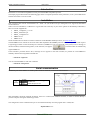
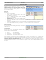
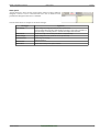
Project/product code:
FM581
Description:
FM581 Configuration Terminal Ver. 1.01
Document type:
User manual
FRANCESCHI MARINA S.n.c.
ELETTRONICA INDUSTRIALE
Via Verga, 5 int.6
20842 Besana in B.za (MB), Italy
Tel.0362-802070 - Fax. 0362-802648
e-mail: [email protected] – web: www.franconline.com
FM581 Configuration Terminal
Arosio Lorenzo
Manuale d’uso
FRANCESCHI MARINA S.N.C.
12/10/11
2
FM581 Configuration Terminal
Manuale d’uso
12/10/11
Indice generale
FM581....................................................................................................................................1
FM581 Configuration Terminal Ver. 1.01...........................................................................1
User manual.......................................................................................................................1
Introduction....................................................................................................................1
Installation.....................................................................................................................1
Serial communication....................................................................................................1
Main window..................................................................................................................2
Button bar..................................................................................................................2
System state panel....................................................................................................2
Command panel........................................................................................................2
Alarm panel...............................................................................................................3
Setup window................................................................................................................4
Button bar..................................................................................................................4
Options panel............................................................................................................4
Parameters pages.....................................................................................................5
Nominal values.....................................................................................................5
Speed....................................................................................................................5
Loop-Controller calibration....................................................................................5
Analog input offset calibration..............................................................................5
Field bus................................................................................................................5
Oscilloscope..................................................................................................................6
Arosio Lorenzo
FRANCESCHI MARINA S.N.C.
3
FM581 Configuration Terminal
User manual
12/10/11
Introduction
Parameters are accessible through RS232 serial port with ModBus compatible protocol.
The simple program described in the following pages shows a complete panoramic of the parameters, to carry out modifications
and tests and at last to save all to disk.
Installation
This program works with PC with Windows NT / 2000 / XP (98 ed ME serial port management not supported) and RS232
serial connection.
There isn't a true installation, it sufficient to copy the files into a directory of your choice (please not the desktop of Windows).
Here a list of the supplied file:
✗
FM581_ConfigTerm_v???.exe
✗
FM581_Parameters.par
✗
FM581_ConfigTerm.ini
✗
MBServer.exe
✗
MBServer.txt
Serial communication is based on a subset of functions of the ModBus standard protocol, see www.modbus.org.
The file MBServer.exe contains an ActiveX control that implements the ModBus protocol: this is the only element that requires
a registering procedure. To the first attempt of connection (if MBServer is not yet registered in the system) an error message, in
the main window, and the following button, in the menu bar, will appear:
Click this button to automatically
register MBServer.
If this automatic procedure had to fail (a message of error appears in the main window) it's possible to record MBServer
manually with the following DOS command line:
> mbserver /regserver
You can uninstall MBServer with this command:
> mbserver /unregserver
Serial communication
The RS232 port on the FM581 is a small 4 poles connector named J2, connected as described here:
J2
(RS232)
1
2
3
4
TX Data
RX Data
GND
GND
RS232: 19200,8E1+ RTS-Toggle
ModBus RTU
Usare cavo tipo AT-Link
With the FM581 should be supplied an adapter, from J2 to a DB-9 male standard connector, in order to connect directly a
personal computer through an AT-Link type cable.
The configuration of the communication port is executed automatically from the program and is: 19200, 8E1.
Default address is 1.
Arosio Lorenzo
Franceschi Marina s.n.c..
1
FM581 Configuration Terminal
User manual
12/10/11
Main window
Attention: the content of the described windows can be modified or
masked automatically, based on the actual configuration. Only the
parameters in use are accessible to the customer. When a field
parameters is grayed it means that the parameter is not used in the
way of operation configured.
Button bar
From the left:
•
“Exit”: close the program.
•
“COM?”: COM1 – 8 serial port selection. Select the port
where the drive is connected to.
•
“Slave #?”: ModBus slave address selection. Select the
address of the desired device.
•
“Connect”/”Disconnect”: activate/deactivate the ModBus
communication.
•
“Drive Setup”: Show/Hide the setup window. From the setup window you can see and edit the parameters (see next
paragraphs).
•
“Oscilloscope”: Show/Hide oscilloscope window. This window shows some diagram of the main parameters.
•
“About”: shows an about-box where you can see also version codes and address of the connected device.
System state panel
This panel shows the main working values: supply voltage, motor
voltage and current.
Command panel
From this panel you can control the enable signals and define a
setpoint for speed or current, from remote:
●
●
●
“Inhibit”
“Disable CW”
“Disable CCW”
drive inhibit signal
move clockwise disable
move counter-clockwise disable
In the setup options you can select the control from ModBus, in this case you can control remotely the drive. If hardware input
option is selected, the state of the buttons is only a mirror of the state of the hardware inputs (see next paragraphs for details).
The setpoint is axpressed in percentage over the +/-10V range of the analog input, and it can be a speed reference or a current
reference according to the working mode of the control.
The buttons with the arrow increases an decreases the setpoint by steps of 0,1-1-10%, when is configured ModBus as source of
the setpoint.
Arosio Lorenzo
Franceschi Marina s.n.c..
2
FM581 Configuration Terminal
User manual
12/10/11
Alarm panel
“Actual Fault List” shows all the present alarms. When an alarm condition
disappear it leaves a trace in “Previous Fault List”; this is usefull to track
problems that disappear when drive is disabled.
The next table shows an example of the alarm messages:
Messaggio
Significato
Over Voltage
Supply voltage is too high (oltre 100V or 195V by drive size).
This can happen when the motor works braking a big load, in such case is necessary to
equip the supply of a braking device to maintain the voltage under threshold.
Over Current
Current is too high, out of control (over 28A or 14A by drive size).
Under Voltage
Supply voltage is too low (under 20V or 40V by drive size)
Overheat Power
Power stage Overheating
Short Circuit
Output shortcircuit
Tacho Alarm
Tachometer anomaly: short, open, reversed
Arosio Lorenzo
Franceschi Marina s.n.c..
3
FM581 Configuration Terminal
User manual
12/10/11
Setup window
Attention: the options setup defines wich parameters are active and editable (grayed fields or not).
Button bar
From the left:
•
“Close”: closing the window will appear some
message to remember to send, save or export to file
your work before continue, this because at the next
time you open the setup window, it will display
refreshed values from the actual drive setup.
•
“Reload”: refresh all data from the drive, overwriting
every modifications to this window.
•
“Send To Drive”: sends all data to the drive, where
they are immediatly active. New values of the
parameters are not saved permanently. You can turnoff the drive to delete this setup.
•
“Save To Drive”: sends all data to the drive, and save
permanently this setup.
•
“From File...”: load the setup from a file (previously
saved to disk) to the setup window.
•
“To File...”: save a file containing the setup
information to disk.
•
“Print”: create a small printable report with all the
values assigned.
The modifications brought to the setup window modify the programming only acting on the buttons “Send” and/or “Save”.
Expoting to file and printing take all data from the actual values shown in the setup window, that can be different from the
actual drive programming. Use “Reload“ to refresh the setup window or “Send”/”Save” to update the drive program.
Options panel
Reference source: select the source of setpoint (speed/current), from analog input or from
fieldbus (ModBus over RS232).
•
Input source: select the source of commands, from hardware inputs or from fiedlbus
(ModBus over RS232).
•
Active level: choose the active level for the digital inputs. Remember to connect the jumper
JP3 to pull-up or pull-down the inputs.
•
Variable current limit: enable the auxiliary analog input, used to apply a variable limit to the
current.
•
Feedback mode: select the type of feedback signal in speed-mode, Back-EMF or DCTachometer.
•
Ramp mode: enable acceleration and deceleration ramps.
•
Stop mode: select braking mode. The 'Free-wheel' option leaves the motor free when the
drive is disabled. The 'Ramp/Block-wheel' option executes acceleration/deceleration ramps
if “With ramp” is selected, else it try to block the shaft as rapidly as it's possible, in current
limit.
•
Auto calibration: activate the procedure of autocalibration of the analog input (current,
Bakc-EMF, tacho...) at the startup. By default this is active, but if you are in the case where
the shaft is already moving at the startup, it can be necessary to disable.
•
Tacho alarm: enable the tachometer anomaly alarm. This works only in speed mode and
with tachometer feedback. The alarm cause the drive to switch to Back-EMF feedback and
disable the drive in the way defined by the previous options (ramps, free-wheel, brake ...).
Loop mode: select the control mode, you can anble only the current loop (current mode) or a current+speed loop
(speed mode).
•
•
Arosio Lorenzo
Franceschi Marina s.n.c..
4
FM581 Configuration Terminal
User manual
12/10/11
Parameters pages
Nominal values
This pages contain the nominal values of the motor.
Maximun current is used to realize an I 2T protection mechanism in speed
mode: you can supply an overcurrent for a limited time.
Speed
Here you can setup the duration of ramps (when ramps are enabled),
tachometer specifications (voltage-speed coefficient and the value of the
series resistor, if it exists) and RxI compensation (armature series
resistance).
Loop-Controller calibration
The current loop have a PI regulator, while the speed loop have a PID
regulator. In this page you can view and edit the gain values of the every
conponent of the regulator to optimize the calibration.
Analog inputs are digitaly filtered (for noise reduction), here you can
select the cut-frequency or disable the filter.
Analog input offset calibration
It's possible to correct the offset of the two analog inputs (main analog
setpoint input and auxiliary current limit input).
The arrow buttons allow to modify the value and observe the effect.
It's possible to assign a gain factor, from -1 to +1, to the main analog
inpute to scale the value.
Field bus
ModBus needs to assign an address to every device connected to a
ModBus network. In this case RS232 is not suitable to realize a network,
however it's available the address as a modifiable parameter. Dafult
value is 1 (don't change it if not really necessary).
Attention: to save the changes use the “<=Save” button on the right. “Send” and “Save” buttons in the main button bar have no
effect in this case.
Attention: any modification will be active at the next restart, you must turn off the drive and restart it.
Arosio Lorenzo
Franceschi Marina s.n.c..
5
FM581 Configuration Terminal
User manual
12/10/11
Oscilloscope
This window contains four diagrams that show a
track of the main parameters (dc-bus/supply
voltage, Back-EMF voltage, current...).
The diagrams overlaps to the trace of the main
variable the course of the related parameters, like
minimum and maximum value or feedback and
reference values etc...
One of the four diagrams is magnified, while the
remaining are smaller in the high part of the
window. In order to magnify one of the small
diagrams, select it with a click of the mouse.
1.
2.
3.
4.
Dc-Bus diagram: shows the supply voltage. It allows to estimate the amplitude of the variations during acceleration
and deceleration.
Current diagram: shows the motor current and it makes evident the current limits, that are variable when the auxiliary
current limit input is used. In current mode it shows also the current setpoint.
Back-EMF diagram: is just a rappresentation of the Back-EMF in volt.
Speed diagram: show any information about speed like Back-EMF, speed feedback and speed setpoint (when speed
mode is configured). All values are expressed in percentage, over the +/-10V range of the analog input, to make more
easy the comparison. When Back-EMF feedback is selected, the feedback track and the armature track are overlapped.
This scope is a usefull instrument to calibrate the current PI and speed PID loop regulators.
Arosio Lorenzo
Franceschi Marina s.n.c..
6