1
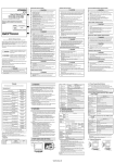
9 Thank you for purchasing the GOT2000 Series. 0 Prior to use, please read both this manual and the detailed manual thoroughly to fully understand the product. 1 2 3 MODEL GT23-U-GD-E Model code 1D7MI4 4 5 IB(NA)-0800503ENG-B(1309)MEE 6 7 8 9 0 lSAFETY PRECAUTIONSl (Always read these precautions before using this equipment.) Before using this product, please read this manual and the relevant manuals introduced in this manual carefully and pay full attention to safety to handle the product correctly. The precautions given in this manual are concerned with this product. In this manual, the safety precautions are ranked as "WARNING" and "CAUTION". WARNING Indicates that incorrect handling may cause hazardous conditions, resulting in death or severe injury. CAUTION Indicates that incorrect handling may cause hazardous conditions, resulting in medium or slight personal injury or physical damage. Note that the CAUTION level may lead to a serious accident according to the circumstances. Always follow the instructions of both levels because they are important to personal safety. Please save this manual to make it accessible when required and always forward it to the end user. Some failures of the GOT, communication unit or cable may keep the outputs on or off. Some failures of a touch panel may cause malfunction of the input objects such as a touch switch. An external monitoring circuit should be provided to check for output signals which may lead to a serious accident. Not doing so can cause an accident due to false output or malfunction. Do not use the GOT as the warning device that may cause a serious accident. An independent and redundant hardware or mechanical interlock is required to configure the device that displays and outputs serious warning. Failure to observe this instruction may result in an accident due to incorrect output or malfunction. The GOT backlight failure disables the operation on the touch switch(s). When the GOT backlight has a failure, the POWER LED blinks (orange/blue) and the display section dims. In such a case, the input by the touch switch(s) is disabled. The display section of the GOT is an analog-resistive type touch panel. If you touch the display section simultaneously in 2 points or more, the switch that is located around the center of the touched point, if any, may operate. Do not touch the display section in 2 points or more simultaneously. Doing so may cause an accident due to incorrect output or malfunction. When programs or parameters of the controller (such as a PLC) that is monitored by the GOT are changed, be sure to reset the GOT, or turn on the unit again after shutting off the power as soon as possible. Not doing so can cause an accident due to false output or malfunction. If a communication fault (including cable disconnection) occurs during monitoring on the GOT, communication between the GOT and PLC CPU is suspended and the GOT becomes inoperative. A system where the GOT is used should be configured to perform any significant operation to the system by using the switches of a device other than the GOT on the assumption that a GOT communication fault will occur. Not doing so can cause an accident due to false output or malfunction. Manuals Be sure to shut off all phases of the external power supply used by the system before mounting or removing the GOT main unit to/from the panel. Not doing so can cause the unit to fail or malfunction. CAUTION Use the GOT in the environment that satisfies the general specifications described in this manual. Not doing so can cause an electric shock, fire, malfunction or product damage or deterioration. When mounting the GOT to the control panel, tighten the mounting screws in the specified torque range (0.36 N•m to 0.48 N•m) with a Phillips-head screwdriver No.2. Undertightening can cause the GOT to drop, short circuit or malfunction. Overtightening can cause a drop, short circuit or malfunction due to the damage of the screws or the GOT. Remove the protective film of the GOT. When the user continues using the GOT with the protective film, the film may not be removed. Operate and store the GOT in environments without direct sunlight, high temperature, dust, humidity, and vibrations. When using the GOT in the environment of oil or chemicals, use the protective cover for oil.Failure to do so may cause failure or malfunction due to the oil or chemical entering into the GOT. [WIRING PRECAUTIONS] CAUTION Make sure to ground the FG terminal and LG terminal of the GOT power supply section to the protective ground conductors dedicated to the GOT with a ground resistance of 100 Ω or less. When tightening the terminal screws, use a Phillips-head screwdriver No.2. Terminal screws which are not to be used must be tightened always at torque 0.5 N•m to 0.8 N•m. Otherwise there will be a danger of short circuit against the solderless terminals. Use applicable solderless terminals and tighten them with the specified torque. If any solderless spade terminal is used, it may be disconnected when the terminal screw comes loose, resulting in failure. Correctly wire the GOT power supply section after confirming the rated voltage and terminal arrangement of the product. Not doing so can cause a fire or failure. Tighten the terminal screws of the GOT power supply section in the specified torque range (0.5 N•m to 0.8 N•m). Undertightening can cause a short circuit or malfunction.Overtightening can cause a short circuit or malfunction due to the damage of the screws or the GOT. 2. PART NAMES AND SETTINGS The following shows manuals relevant to this product. The following shows the part names for GT2310 and GT2308. Example:GT2310 Detailed Manual Manual name Manual number (Model code) 5) 4) 4) SH-081194ENG-A(1D7MJ5) GOT2000 Series User’s Manual (Utility) SH-081195ENG-A(1D7MJ6) 6) 7) 1)2) 8) 9) 3) GOT2000 Series User’s Manual (Hardware) 10) 13) 12) 4) 4) 11) No. Name 1) Display screen 2) Relevant Manuals For relevant manuals, refer to the Help or the PDF manuals stored in the DVDROM or CD-ROM for the drawing software used. The latest manuals are also available from MITSUBISHI ELECTRIC FA Global Website (http://www.MitsubishiElectric.co.jp/fa/). 3) 4) 5) 6) © 2013MITSUBISHI ELECTRIC CORPORATION Before using the GOT 7) Connect the connector of the GOT to the connector of the battery (GT11-50BAT, sold separately). Refer to the GOT2000 Series User’s Manual (Hardware) for the connection instructions. For details on the GOT specifications, installing instructions, wiring, maintenance and inspection, or checking procedure for the version and the compatible standard, refer to the GOT2000 Series User’s Manual (Hardware). Packing List 8) 9) 10) 11) The GOT product package includes the following: Description Quantity GT23 1 Installation fitting 4 GT23 General Description 1 1. FEATURES (1) Abundant standard equipment • Variety of connection with FA devices • SD card interface compatible with the SDHC card having a large capacity and allowing high-speed communication • Connection with various peripheral devices with the USB host (2) Improved usability • Abundant troubleshooting • Easy and clear screen creation • PC-like operation screen (3)Enhanced compatibility with Mitsubishi FA devices (4)Easy replacement (5)LED backlight 12) Description Displays the utility and the user-created screen. For operating the touch switches in the utility and the userTouch Pane created screen Lit in blue : Power is properly supplied. Lit in orange : Screen saving POWER LED Blinks in orange/blue : Backlight failure Not lit : Power is not supplied Unit installation fitting Mounting fixtures for fixing the GOT to the control panel Installation switch Used for OS installations at the GOT startup Lit: SD card mounted Blinking: SC card accessed SD card access LED No lit: SD card not mounted or SD card mounted (removable) SD card interface For installing a SD card With a switching function for accepting and stopping the access to the SD card SD card cover When the cover is opened : Access is prohibited When the cover is closed : Access is allowed For connecting a USB mouse, connecting a USB keyboard, USB interface (Host) data transfer, and data storage (connector type: TYPE-A) For connecting a personal computer (connector type: MiniUSB interface (Device) B) Hole for attaching a cable clamp for preventing USB cable Hole for attaching a from being pulled out cable clamp (Recommended product: RSG-130-V0 made by KITAGAWA INDUSTRIES CO.,LTD) Terminating resistor For switching on and off of the terminating resistor for the setting switch RS-422 and RS-485 communication port (Default (Off)) (Inside cover) 13) 14) Battery holder Power terminal 15 Ethernet interface 16) RS-232 interface 17) RS-422/485 interface Houses the battery Power input terminal, LG terminal, FG terminal For communicating with a controller or connecting a personal computer (connector type: RJ-45 (modular jack)) For communicating with a controller (Connector type: D sub 9-pin (male)) For communicating with a controller (Connector type: D sub 9-pin (female)) 3. SPECIFICATIONS Item [DISPOSAL PRECAUTIONS] *1: If ambient temperature exceeds 40 , do not exceed absolute humidity 40 90%. *2: Do not use or store the GOT under pressure higher than the atmospheric pressure of altitude 0m (0ft.). Failure to observe this instruction may cause a malfunction. When an air purge is made inside the control panel by adding pressure, there may be a clearance between the surface sheet and the screen making it difficult to use the touch panel, or the sheet may come off. *3: This indicates the section of the power supply to which the equipment is assumed to be connected between the public electrical power distribution network and the machinery within the premises. Category II applies to equipment for which electrical power is supplied from fixed facilities. The surge voltage withstand level for up to the rated voltage of 300 V is 2500 V. *4: This index indicates the degree to which conductive material is generated in the environment where the equipment is used. In pollution degree 2, only non-conductive pollution occurs but temporary conductivity may be produced due to condensation. 3.3 External Dimensions Refer to the GOT2000 Series User’s Manual (Hardware) for details on the performance specifications of each GOT. The following indicates the power supply specifications for GT23. Note Operation at momentary failure • If an instantaneous power failure occurs in the power supply and continues for more than the permissible period, the GOT will be reset. • Make sure to power on the unit more than 5 seconds after power-off. 3.2.1 For GOTs powered from the 100 to 240VAC power supply Item Power supply voltage Specifications GT2310-VTBA Input max. apparent power maximum load Power Stand alone consum ption Stand alone with backlight off 50,60Hz 5% 44VA (maximum load) 30VA (maximum load) 18W or less 11W or less 15W 9W 8W 6W 40A or less (4ms, operating ambient temperature 25 , maximum load) Inrush current Allowable momentary power failure time 20 ms or less (100VAC or more) Noise immunity 1,500Vp-p noise voltage, 1 s noise width (when measuring with a noise simulator under 25 to 60Hz noise frequency) Dielectric withstand voltage 1500VAC for 1 minute across power terminals and earth Insulation resistance 10M or more across power terminals and earth by a 500V DC insulation resistance tester 0.75[mm2] to 2[mm2] Solderless terminal for M3 screw RAV1.25-3, V2S3.3, V2-N3A, FV2-N3A Applicable tightening torque (Terminal block terminal screw) Specifications GT2308-VTBA AC100 to 240VAC (+10%, -15%) Power frequency 0.5[N•m] to 0.8[N•m] 0 to 55 3.2.2 For GOTs powered from the 24VDC power supply -20 to 60 10 to 90% RH, non-condensing*1 10 to 90% RH, non-condensing*1 Halfamplitude Item Sweep count 10 times each in X, Y and Z directions Compliant 5 to 8.4Hz 3.5mm Under with JIS B intermittent 3502 and 9.8m/s2 vibration 8.4 to150Hz IEC 61131-2 Under 5 to 8.4Hz 1.75mm continuous 4.9m/s2 vibration 8.4 to 150Hz Compliant with JIS B 3502 and IEC 61131-2 (147 m/s2(15G), 3 times Shock resistance each in X, Y and Z directions) Operating No greasy fumes, corrosive gas, flammable gas, excessive atmosphere conductive dust, and direct sunlight (Same as storage atmosphere) 2000 m (6562 ft) max. Operating altitude*2 Installation location Inside control panel Overvoltage II or less category*3 Pollution degree*4 2 or less Cooling method Self-cooling Type D grounding (100Ω or less). Grounding Connect to panel if unable to ground. Power supply voltage Maximum load Power Stand alone consu mption Stand alone with backlight off Inrush current Allowable momentary power failure time Noise immunity Dielectric withstand voltage Insulation resistance Applicable wire size Applicable solderless terminal Applicable tightening torque (Terminal block terminal screw) CAUTION When disposing of this product, treat it as industrial waste. When disposing of batteries, separate them from other wastes according to the local regulations. (Refer to the GOT2000 Series User’s Manual (Hardware) for details of the battery directive in the EU member states.) [TRANSPORTATION PRECAUTIONS] CAUTION When transporting lithium batteries, make sure to treat them based on the transport regulations. (Refer to the GOT2000 Series User’s Manual (Hardware) for details of the regulated models.) Make sure to transport the GOT main unit and/or relevant unit(s) in the manner they will not be exposed to the impact exceeding the impact resistance described in the general specifications of this manual, as they are precision devices. Failure to do so may cause the unit to fail. Check if the unit operates correctly after transportation. When fumigants that contain halogen materials such as fluorine, chlorine, bromine, and iodine are used for disinfecting and protecting wooden packaging from insects, they cause malfunction when entering our products. Please take necessary precautions to ensure that remaining materials from fumigant do not enter our products, or treat packaging with methods other than fumigation (heat method). Additionally, disinfect and protect wood from insects before packing products. GT2310 GT2308 303 (11.93) 208 (8.19) 228 (8.98) 288 (11.34) 241 (9.49) 166 (6.54) 166 (6.54) 226 (8.90) Unit : mm (inch) 4. EMC AND LOW VOLTAGE DIRECTIVE 3.2 Power Supply Specifications Applicable solderless terminal Frequency Acceleration Vibration resistance CAUTION If the data storage mounted on the GOT is removed while the GOT is accessed, the data storage and files are damaged.To remove the data storage from the GOT, check that the access to the data storage in SD card access LED, the system signal, and others is not performed. When inserting a SD card into the GOT, make sure to close the SD card cover. Failure to do so causes the data not to be read or written. When removing the SD card from the GOT, make sure to support the SD card by hand as it may pop out.Failure to do so may cause the SD card to drop from the GOT, resulting in a failure or break. When inserting a USB device into a USB interface of the GOT, make sure to insert the device into the interface firmly.Failure to do so may cause the USB device to drop from the GOT, resulting in a failure or break Before removing the USB device from the GOT, follow the procedure for removal on the utility screen of the GOT. After the successful completion dialog is displayed, remove the USB device by hand carefully.Failure to do so may cause the USB device to drop from the GOT, resulting in a failure or break. Do not disassemble or modify the unit. Doing so can cause a failure, malfunction, injury or fire. Do not touch the conductive and electronic parts of the unit directly. Doing so can cause a unit malfunction or failure. The cables connected to the unit must be run in ducts or clamped. Not doing so can cause the unit or cable to be damaged due to the dangling, motion or accidental pulling of the cables or can cause a malfunction due to a cable connection fault. When unplugging the cable connected to the unit, do not hold and pull from the cable portion. Doing so can cause the unit or cable to be damaged or can cause a malfunction due to a cable connection fault. Do not drop the module or subject it to strong shock. A module damage may result. Do not drop or give an impact to the battery mounted to the unit. Doing so may damage the battery, causing the battery fluid to leak inside the battery. If the battery is dropped or given an impact, dispose of it without using. Before touching the unit, always touch grounded metals, etc. to discharge static electricity from human body, etc. Not doing so can cause the unit to fail or malfunction. Use the battery manufactured by Mitsubishi Electric Corporation. Use of other batteries may cause a risk of fire or explosion. Dispose of used battery promptly. Keep away from children.Do not disassemble and do not dispose of in fire. Be sure to shut off all phases of the external power supply before replacing the battery or using the dip switch of the terminating resistor. Not doing so can cause the unit to fail or malfunction by static electricity. Applicable wire size 3.1 General Specifications Operating ambient temperature Storage ambient temperature Operating ambient humidity Storage ambient humidity WARNING If the SD card mounted on drive A of the GOT is removed while the GOT is accessed, processing for the GOT might be interrupted about for 20 seconds.The GOT cannot be operated during this period. The functions that run in the background including a screen updating, alarm, logging, scripts, and others are also interrupted.Since this interruption makes an impact to the system operation, it might cause failure.After checking the light off of SD card access LED, remove the SD card. CAUTION When power is on, do not touch the terminals. Doing so can cause an electric shock or malfunction. Correctly connect the battery connector. Do not charge, disassemble, heat, short-circuit, solder, or throw the battery into the fire. Doing so will cause the battery to produce heat, explode, or ignite, resulting in injury and fire. Before starting cleaning or terminal screw retightening, always switch off the power externally in all phases. Not switching the power off in all phases can cause a unit failure or malfunction. Undertightening can cause a short circuit or malfunction. Overtightening can cause a short circuit or malfunction due to the damage of the screws or unit. Point 17) 16)15) 14) For detailed manuals, refer to the PDF manuals stored in the DVD-ROM or CDROM for the drawing software used. [STARTUP/MAINTENANCE PRECAUTIONS] [PRECAUTIONS WHEN THE DATA STORAGE IS IN USE] WARNING WARNING Be sure to shut off all phases of the external power supply used by the system before wiring. Failure to do so may result in an electric shock, product damage or malfunctions. WARNING WARNING Before performing the test operations of the user creation monitor screen (such as turning ON or OFF bit device, changing the word device current value, changing the settings or current values of the timer or counter, and changing the buffer memory current value), read through the manual carefully and make yourself familiar with the operation method. During test operation, never change the data of the devices which are used to perform significant operation for the system. False output or malfunction can cause an accident. [MOUNTING PRECAUTIONS] WARNING [DESIGN PRECAUTIONS] [TEST OPERATION PRECAUTIONS] 194 (7.64) 8 56 (2.20) 6 (0.24) 7 For the analog-resistive film type touch panels, normally the adjustment is not required. However, the difference between a touched position and the object position may occur as the period of use elapses. When any difference between a touched position and the object position occurs, execute the touch panel calibration. When any difference between a touched position and the object position occurs, other object may be activated. This may cause an unexpected operation due to incorrect output or malfunction. 10 (0.39) 6 Exercise care to avoid foreign matter such as chips and wire offcuts entering the GOT. Not doing so can cause a fire, failure or malfunction. Plug the communication cable into the GOT interface or the connector of the connected unit, and tighten the mounting screws and the terminal screws in the specified torque range. Undertightening can cause a short circuit or malfunction. Overtightening can cause a short circuit or malfunction due to the damage of the screws or unit. 218 (8.58) GT2310-VTBD GT2308-VTBD CAUTION CAUTION Do not bundle the control and communication cables with main-circuit, power or other wiring. Run the above cables separately from such wiring and keep them a minimum of 100mm apart. Not doing so noise can cause a malfunction. Do not press the GOT display section with a pointed material as a pen or driver. Doing so can result in a damage or failure of the display section. When the GOT is connected to the Ethernet network, the available IP address is restricted according to the system configuration. • When multiple GOTs are connected to the Ethernet network : Do not set the IP address (192.168.3.18) for the GOTs and the controllers in the network. • When a single GOT is connected to the Ethernet network : Do not set the IP address (192.168.3.18) for the controllers except the GOT in the network. Doing so can cause the IP address duplication. The duplication can negatively affect the communication of the device with the IP address (192.168.318). The operation at the IP address duplication depends on the devices and the system. Turn on the controllers and the network devices to be ready for communication before they communicate with the GOT. Failure to do so can cause a communication error on the GOT. When the GOT is subject to shock or vibration, or some colors appear on the screen of the GOT, the screen of the GOT might flicker. 56 (2.20) 6 (0.24) GT2310-VTBA GT2308-VTBA 5 [TOUCH PANEL PRECAUTIONS] 10 (0.39) GT23 General Description 3 4 [WIRING PRECAUTIONS] CAUTION 175 (6.89) 10 (0.39) [DESIGN PRECAUTIONS] 2 199 (7.84) 10 (0.39) 1 Specifications GT2310-VTBD GT2308-VTBD DC24V (+25%, -20%) 16W or less 11W or less 13W 8W 7W 6W 40A or less (2ms, operating ambient temperature 25 , maximum load) 10 ms or less 500Vp-p noise voltage, 1 s noise width (when measuring with a noise simulator under 25 to 60Hz noise frequency) 350VAC for 1 minute across power terminals and earth 10M or more across power terminals and earth by a 500V DC insulation resistance tester 0.75[mm2] to 2[mm2] Solderless terminal for M3 screw RAV1.25-3, V2S3.3, V2-N3A, FV2-N3A 0.5[N•m] to 0.8[N•m] For the products sold in European countries, the conformance to the EMC Directive, which is one of the European Directives, has been a legal obligation since 1996. Also, conformance to the Low Voltage. Directive, another European Directives, has been a legal obligation since 1997. Manufacturers who recognize their products must conform to the EMC and Low Voltage Directive are required to declare that their products conform to these Directives and put a "CE mark" on their products. • Authorized representative in Europe Authorized representative in Europe is shown below. Name :Mitsubishi Electric Europe BV Address :Gothaer strase 8, 40880 Ratingen, Germany 4.1 Requirements to Meet EMC Directive EMC Directives are those which require "any strong electromagnetic force is not output to the external.:Emission (electromagnetic interference)" and "It is not influenced by the electromagnetic wave from the external.: Immunity (electromagnetic sensitivity)". Items4.1.1 through4.4.3 summarize the precautions to use GOT and configure the mechanical unit in order to match the EMC directives. Though the data described herein are produced with our best on the basis of the requirement items and standards of the restrictions gathered by Mitsubishi, they do not completely guaranteed that all mechanical unit manufactured according to the data do not always match the above. Applied standard Test standard CISPR16-2-3 Radiated noise*1 CISPR16-2-1 Conducted noise*1 IEC61000-4-2 Electrostatic immunity*1 IEC61000-4-3 Radiated electromagnetic field AM modulation IEC61000-4-4 Fast transient burst noise*1 EN61131-2 : 2007 IEC61000-4-5 Surge immunity*1 IEC61000-4-6 Conducted RF immunity*1 IEC61000-4-8 Power supply frequency magnetic field immunity IEC61000-4-11 Instantaneous power failure and voltage dips immunity Test details Standard value Electromagnetic emissions from the product are measured. Electromagnetic emissions from the product to the power line is measured. Immunity test in which static electricity is applied to the cabinet of the equipment. Immunity test in which field is irradiated to the product. Immunity test in which burst noise is applied to the power line and signal lines. Immunity test in which lightening surge is applied to the product. Immunity test in which a noise inducted on the power and signal lines is applied. Test for checking normal operations under the circumstance exposed to the ferromagnetic field noise of the power supply frequency (50/60Hz). Test for checking normal operations at instantaneous power failure. 30M-230MHz QP: 30dB V/m (30m in measurement range)*2, *3 230M-1000MHz QP: 37dB V/m(30m in measurement range)*2, *3 150k-500kHz QP:79dB, Mean: 66dB*2 500k-30MHz QP:73dB, Mean: 60dB*2 4kV Contact discharge 8kV Aerial discharge 80-1000MHz:10V/m 1.4-2GHz:3V/m 2.0-2.7GHz:1V/m 80%AM modulation@1kHz Power line:2kV Digital I/O(24V or higher): 1kV (Digital I/O(24V or less))> 250V (Analog I/O, signal lines)> 250V AC power type Power line (between line and ground): 2kV Power line (between lines) : 1kV Data communication port : 1kV DC power type Power line (between line and ground) : 0.5kV Power line (between lines) : 0.5kV Data communication port : 1kV Power line: 10V Data communication port: 10V 4.1.3 Noise filter (power supply line filter) The noise filter (power supply line filter) is a device effective to reduce conducted noise. Except some models, installation of a noise filter onto the power supply lines is not necessary. However conducted noise can be reduced if it is installed. (The noise filter is generally effective for reducing conducted noise in the band of 10MHz or less.) Usage of the following filters is recommended. Model name 30 A/m AC power type 0.5 cycle 0% (interval 1 to 10s) 250/300 cycle 0% 10/12 cycle 40% 25/30 cycle 70% 4.1.2 Control panel The GOT is an open type device (device installed to another device) and must be installed in a conductive control panel. It not only assure the safety but also has a large effect to shut down the noise generated from GOT, on the control panel. (1) Control Panel (a) The control panel must be conductive. (b) When fixing a top or bottom plate of the control panel with bolts, do not coat the plate and bolt surfaces so that they will come into contact. And connect the door and box using a thick grounding cable in order to ensure the low impedance under high frequency. (c) When using an inner plate to ensure electric conductivity with the control panel, do not coat the fixing bolt area of the inner plate and control panel to ensure conductivity in the largest area as possible. (d) Ground the control panel using a thick grounding cable in order to ensure the low impedance under high frequency. (2) CPU direct connection • Attach ferrite cores to the cable in the positions as illustrated below. Ferrite Core (ZCAT3035-1330) PLC side 100 or less (3.94) FN343-3/05 FN660-6/06 RSHN-2003 Manufacturer SCHAFFNER SCHAFFNER TDK Rated current 3A 6A 3A Rated voltage *1: The GOT is an open type device (device installed to another device) and must be installed in a conductive control panel. The above test items are conducted in the condition where the GOT is installed on the conductive control panel and combined with the Mitsubishi PLC. *2: QP (Quasi-Peak): Quasi-peak value, Mean: Average value *3: The above test items are conducted in the following conditions. 30M-230MHz QP : 40dB V/m (10m in measurement range) 230M-1000MHz QP : 47dB V/m (10m in measurement range) GOT side (2) Connection of power and ground wires Ground and power supply wires for the GOT must be connected as described below. (a) Provide a grounding point near the GOT. Short-circuit the LG and FG terminals of the GOT (LG: line ground, FG: frame ground) and ground them with the thickest and shortest wire possible (The wire length must be 30cm (11.81in.) or shorter.) The LG and FG terminals function is to pass the noise generated in the PC system to the ground, so an impedance that is as low as possible must be ensured. As the wires are used to relieve the noise, the wire itself carries a large noise content and thus short wiring means that the wire is prevented from acting as an antenna. Note) A long conductor will become a more efficient antenna at high frequency. (b) The earth wire led from the earthing point must be twisted with the power supply wires. By twisting with the earthing wire, noise flowing from the power supply wires can be relieved to the earthing. However, if a filter is installed on the power supply wires, the wires and the earthing wire may not need to be twisted. 100 or less (3.94) Unit: mm (inch) (3) Computer link connection • Peel the sheath (with the length shown below) at both ends of the cable, and expose the shield braided wire for grounding. (For grounding with cable clamps. (refer to Section 4.4.3.)) GOT side PLC side 250V The precautions required when installing a noise filter are described below. (1) Do not install the input and output cables of the noise filter together to prevent the output side noise will be inducted into the input side cable where noise has been eliminated by the noise filer. Input side (power supply side) Filter • Installing the input and output cables together will cause noise induction. (2) Connect the noise filter's ground terminal to the control panel with the shortest cable as possible (approx. 10cm (3.94 in.) or less). 4.2 Requirements for Compliance with the Low Voltage Directive The Low Voltage Directive requires each device which operates with power supply ranging from 50VAC to 1000V and 75VDC to 1500V to satisfy necessary safety items. In the Sections from 4.2.1 to 4.2.5, cautions on installation and wiring of the GOT to conform to the Low Voltage Directive requires are described. We have put the maximum effort to develop this material based on the requirements and standards of the Directive that we have collected. However, compatibility of the devices which are fabricated according to the contents of this manual to the above Directive is not guaranteed. Each manufacturer who fabricates such device should make the final judgement about the application method of the Low Voltage Directive and the product compatibility. 5.1 Control Panel Inside Dimensions for Mounting GOT Install the GOT on the control panel out of the way for the equipment inside the control panel. Do not install the GOT and the unit in prohibited areas for the installation. Point Applicable cable Some cables may need to be longer than the specified dimensions when connecting to the GOT. Therefore, consider the connector dimensions and bending radius of the cable as well for installation. RDA RDB SDA SDB SDB RDA RDB • Make the SG wire more than two wires and connect. GOT SD SD RD DTR DSR DSR DTR SG SG • Attach the ferrite core to the cable in the position as illustrated below. GOT side Ferrite Core (ZCAT3035-1330) 100 or less (3.94) PLC side 100 or less (3.94) Unit: mm (inch) 4.4.3 Grounding the cable Ground the cable and grounding wire to the control panel where the GOT and base unit are installed. 1) Ground the braided shield portion of the cable to the control panel with the cable clamp (AD75CK). Braided shield Cable clamps For the cable clamp attaching details refer to AD75CK-type Cable Clamping Instruction Manual <IB-68682>. 2) Do not arrange the cable clamp adjacent to other cables which do not clamp. Noise from the control panel may access the GOT from the cable clamp and cause adverse effects. Category I A B 289 (11.38) 200 (7.87) B GT2308 227 (8.94) 176 (6.93) +2 (0.08) 0 (0) +2 (0.08) 0 (0) Unit: mm (inch) When mounting the GOT, the following clearances must be maintained from other structures and devices. Some cables may need to be longer than the specified dimensions when connecting to the GOT. Therefore, consider the connector dimensions and bending radius of the cable as well for installation. For the lead-in allowance for cables at the bottom of the GOT, refer to the GOT2000 Series User’s Manual (Hardware). 4000V 4.3.1 GOT Use any of the GOTs with which CE mark logo is printed on the rating plate. All GT23 models support the EMC Directive. Modify the cables (including user-produced cable) to ensure compliance with the EMC Directive. For details, refer to Section 4.4.2. In addition, for the cables to be used, refer to the GOT2000 Series Connection Manual. 4.2.3 Control panel Wire and connect the GOT2000 series equipment as instructed below. If the GOT2000 series equipment is configured in a way different from the following instructions, the system may not comply with the EMC Directive. Because the GOT is open type equipment (device designed to be stored within another device), be sure to use it only when installed in a control panel. (1) Shock Protection In order to prevent those who are unfamiliar with power facility, e.g., an operator, from getting a shock, make sure to take the following measures on the control panel. (a) Store the GOT within the control panel locked, and allow only those who are familiar with power facility to unlock the panel. (b)Build the structure in order that the power supply will be shut off when the control panel is opened. (2) Dustproof and waterproof features The control panel also provides protection from dust, water and other substances. Insufficient ingression protection may lower the insulation withstand voltage, resulting in insulation destruction. The insulation in the GOT is designed to cope with the pollution level 2, so use in an environment with pollustion level 2 or better. Pollution level 1: Pollution level 2: Pollution level 4: An environment where the air is dry and conductive dust does not exist. An environment where conductive dust does not usually exist, but occasional temporary conductivity occurs due to the accumulated dust. Generally, this is the level for inside the control panel equivalent a control room or on the floor of a typical factory. An environment where conductive dust exits and conductivity may be generated due to the accumulated dust. An environment for a typical factory floor. Continuous conductivity may occur due to rain, snow, etc. An outdoor environment. 4.2.4 Grounding The following are applicable ground terminals. Use them in the grounded state. Be sure to ground the GOT for ensuring the safety and complying with the EMC Directive. Functional grounding 4.4.1 Power and ground wires wiring method (1) Power and ground wires wiring method Connect the power wire and connection cable as shown in the illustration. Lead the power wire and ground wire as shown in Section 4.1.2 (2). Be sure to ground the LG cable and FG cable. 100-240VAC GOT power section When installing the GOT with the installation angle between 60 to 105 °, the temperature inside the control panel must be within 55 °C. When installing the GOT with the installation angle other than between 60 to 105 °, the temperature inside the control panel must be within 40 °C. Display section 60° Panel or others (1)Ethernet connection Strip the outer insulation layer at both ends of the cable by the length shown below to expose the braided shield for grounding. (For grounding with cable clamps. (refer to Section 4.4.3.)) GOT side Panel thickness: 1.6 to 4mm (0.06 to 0.16 inch) Brazil Germany U.K Italy Spain China According to the dimensions in the following table, leave clearances between the GOT and the other devices. The values enclosed in square brackets apply to the case where no other equipment generating radiated noise (such as a contactor) or heat is installed near the GOT. However, keep the ambient temperature of the GOT to 55°C or lower. Unit : mm(inch) Taiwan Korea C A B 48(1.89) or more [18(0.71) or more] 78(3.07) or more [18(0.71) or more] When the SD card is used GT2310 :50(1.97) or more [20(0.79) or more] GT2308 :50(1.97) or more When the SD card is not used D E*1 50(1.97) or more 50(1.97) or more 100(3.94) or more [20(0.79) or more] [20(0.79) or more] [20(0.79) or more] Unit: mm (inch) Country/Region Sales office/Tel Hong Kong A 400 or less (15.75) For safe use South Africa E 40 (1.57) • This product has been manufactured as a general-purpose part for general industries, and has not been designed or manufactured to be incorporated in a device or system used in purposes related to human life. • Before using the product for special purposes such as nuclear power, electric power, aerospace, medicine or passenger movement vehicles, consult with Mitsubishi. • This product has been manufactured under strict quality control. However, when installing the product where major accidents or losses could occur if the product fails, install appropriate backup or failsafe functions in the system. France D 40 (1.57) Mitsubishi will not be held liable for damage caused by factors found not to be the cause of Mitsubishi; machine damage or lost profits caused by faults in the Mitsubishi products; damage, secondary damage, accident compensation caused by special factors unpredictable by Mitsubishi; damages to products other than Mitsubishi products; and to other duties. B C PLC/personal computer side Warranty U.S.A 6. MAINTENANCE AND INSPECTION (LG) (FG) Process the cable used with the GOT with the following method. When processing the cable, ferrite core and cable clamp are required. The cable clamp used by Mitsubishi Electric for the EMC specification compatibility test is shown below. • TDK corporation brand ZCAT3035-1330 Ferrite Core • Mitsubishi Electric Model AD75CK cable clamp • Japan Zipper Tubing Co., Ltd. Zipper tube SHNJ type 230 or less (9.06) When installing the GOT to a panel, set the display section as shown below. Using the GOT with the installation angle other than the following deteriorates the GOT earlier. INPUT 24VDC - + 4.4.2 Processing connection cables : Improves the noise resistance. (1) External devices When a device with a hazardous voltage circuit is externally connected to the GOT, select a model which complies with the Low Voltage Directive's requirements for isolation between the primary and secondary circuits. 24VDC GOT power section INPUT 100-240VAC (LG) (FG) 4.2.5 External wiring Refer to the GOT2000 Series User’s Manual (Hardware) for maintenance and inspection for the GOT. 5.3 Mounting Position 300 VAC or below 4.3 EMC Directive-Compliant System Configuration 4.4 EMC Directive-Compliant System Configuration +2 (0.08) 0 (0) 0 (0) 2500V Category II indicates a power supply whose voltage has been reduced by two or more levels of isolating transformers from the public power distribution. 105° GT2310 +2 (0.08) (b) For RS-232 cable Use a twisted pair style for each signal wire (except SG, FG) with SG. RD Category III Category II Installation category GOT Point SDA Category IV *Panel thickness : 1.6 to 4 mm (0.06 to 0.16 inch) A Surge withstand voltage (1.2/50 s) 150 VAC or below 4.3.2 Cables 5.4 Control Panel Inside Temperature and Installation Angle 5. INSTALLATION (4) When connecting to PLC (manufactured by other company), microcomputer, temperature controller, inverter, servo amplifier, CNC, MODBUS(R)/RTU or MODBUS(R)/TCP connection. Produce the cable (RS-232 cable, RS-422 cable) for connecting the GOT to a controller with reference to the GOT2000 Series Connection Manual. (a) For RS-422/485 cable • Each signal wire (excluding SG and FG) should be made into a two power wires and connected, then twisted. The insulation specification of the GOT was designed assuming installation category II. Be sure to use the installation category II power supply to the GOT. The installation category indicates the durability level against surge voltage generated by lightning strike. Category I has the lowest durability; category IV has the highest durability. Pollution level 3: • Separate the input cable from the output cable. Rated voltage of hazardous voltage area 4.2.2 Power supply Output side (device side) Output side (device side) EN61131-2 Programmable controllers - Equipment requirements and tests (2) Insulation requirements Dielectric withstand voltages are shown in the following table. Reinforced Insulation Withstand Voltage (Installation Category II, source : IEC664) EN60950-1 Safety of Information Technology Equipment Induction Filter 40 230 or less (1.57) (9.06) Unit: mm (inch) Configure the system to meet the EMC Directive specifications for the connected device when connecting the GOT to a controller. The following gives the instructions to ensure the machinery comply with the EMC Directive. However, the manufacturer of the machinery must finally determine how to make it comply with the EMC Directives: if it is actually compliant with the EMC Directives. Standard applied to GOT : Input side (power supply side) 5.2 Panel Cutting Dimensions 230 or less 40 (9.06) (1.57) 4.2.1 Standard subject to GOT 90mm or less The standards of the EMC Directive are shown below. (e) The diameter of cable holes in the control panel must be 10cm (3.94in.). In order to reduce the chance of radio waves leaking out, ensure that the space between the control panel and its door is small as possible. Paste the EMI gasket directly on the painted surface to seal the space so that the leak of electric wave can be suppressed. Our test has been carried out on a panel having the damping characteristics of 37dB max. and 30dB mean (measured by 3m method with 30 to 300MHz). 90mm or less 4.1.1 EMC directive Singapore Thailand Indonesia *1: When opening or closing the battery cover: 72(2.83) or more India Australia Mitsubishi Electric Automation Inc. 500 Corporate Woods Parkway Vernon Hills, IL 60061, U.S.A. Tel : +1-847-478-2100 MELCO-TEC Rep. Com.e Assessoria Tecnica Ltda. Rua Correia Dias, 184, Edificio Paraiso Trade Center-8 andar Paraiso, Sao Paulo, SP Brazil Tel : +55-11-5908-8331 Mitsubishi Electric Europe B.V. German Branch Gothaer Strasse 8 D-40880 Ratingen, GERMANY Tel : +49-2102-486-0 Mitsubishi Electric Europe B.V. UK Branch Travellers Lane, Hatfield, Hertfordshire., AL10 8XB, U.K. Tel : +44-1707-276100 Mitsubishi Electric Europe B.V. Italian Branch Centro Dir. Colleoni, Pal. Perseo-Ingr.2 Via Paracelso 12, I-20041 Agrate Brianza., Milano, Italy Tel : +39-039-60531 Mitsubishi Electric Europe B.V. Spanish Branch Carretera de Rubi 76-80, E-08190 Sant Cugat del Valles, Barcelona, Spain Tel : +34-93-565-3131 Mitsubishi Electric Europe B.V. French Branch 25, Boulevard des Bouvets, F-92741 Nanterre Cedex, France Tel : +33-1-5568-5568 Circuit Breaker Industries Ltd. Private Bag 2016, ZA-1600 Isando, South Africa Tel : +27-11-928-2000 Mitsubishi Electric Automation (Hong Kong) Ltd. 10th Floor, Manulife Tower, 169 Electric Road, North Point, Hong Kong Tel : +852-2887-8870 Mitsubishi Electric Automation (China) Ltd. 4/F Zhi Fu Plazz, No.80 Xin Chang Road, Shanghai 200003, China Tel : +86-21-6120-0808 Setsuyo Enterprise Co., Ltd. 6F No.105 Wu-Kung 3rd.Rd, Wu-Ku Hsiang, Taipei Hsine, Taiwan Tel : +886-2-2299-2499 Mitsubishi Electric Automation Korea Co., Ltd. 1480-6, Gayang-dong, Gangseo-ku Seoul 157-200, Korea Tel : +82-2-3660-9552 Mitsubishi Electric Asia Pte, Ltd. 307 Alexandra Road #05-01/02, Mitsubishi Electric Building, Singapore 159943 Tel : +65-6470-2460 Mitsubishi Electric Automation (Thailand) Co., Ltd. Bang-Chan Industrial Estate No.111 Moo 4, Serithai Rd, T.Kannayao, A.Kannayao, Bangkok 10230 Thailand Tel : +66-2-517-1326 P.T. Autoteknindo Sumber Makmur Muara Karang Selatan, Block A/Utara No.1 Kav. No.11 Kawasan Industri Pergudangan Jakarta - Utara 14440, P.O.Box 5045 Jakarta, 11050 Indonesia Tel : +62-21-6630833 Messung Systems Pvt, Ltd. Electronic Sadan NO:III Unit No15, M.I.D.C Bhosari, Pune-411026, India Tel : +91-20-2712-3130 Mitsubishi Electric Australia Pty. Ltd. 348 Victoria Road, Rydalmere, N.S.W 2116, Australia Tel : +61-2-9684-7777 HEAD OFFICE : TOKYO BUILDING, 2-7-3 MARUNOUCHI, CHIYODA-KU, TOKYO 100-8310, JAPAN NAGOYA WORKS : 1-14, YADA-MINAMI 5-CHOME, HIGASHI-KU, NAGOYA, JAPAN When exported from Japan, this manual does not require application to the Ministry of Economy, Trade and Industry for service transaction permission. Specifications subject to change without notice. Printed in Japan, September 2013.