1
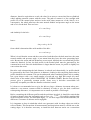
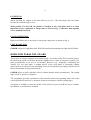
SOFTWARE GSHOB - Version A for WINDOWS NT, 95 or better USER MANUAL Georges STEVENS Jardins de Diane A11 - 291 chemin de Tucaut - 31270 CUGNAUX - France Tél. et Fax 33 5 61 86 53 82 e-mail : [email protected] 1 IMPORTANT This software should not be transferred or copied to the benefit of any other company or people without the author's permission. It use is subject to your acceptance of the conditions accessible from the first page of the software. DESCRIPTION GSHOB provides an efficient way to deal with the problems involved in the design and manufacture of hobs to cut either worm wheels or conventional parallel gears. RUNNING GSHOB GSHOB is protected by a key code. If ignored and in trial period you can however run it and have access to all its functions but only even number of starts are accepted. GSHOB proposes a first menu with the following options : a new hob : to be selected for a new hob. After treatment it will be possible to record it on the hard disc for later recall. read a hob on disc with modifications : to recall an already designed hob and bring it modifications. read a hob on disc without modifications : to recall an already designed hob without modifications. erase a hob on disc : to delete a recorded hob. save the file HOBW.dat or HOBPdat : it is recommended to save periodically these files ; HOBW.dat contains the hobs for worm wheels and HOBP.dat those for parallel gears. RECORDING ON DISC Each time a hob has been created or modified, GSHOB proposes to record it for later recall. It is identified by a reference (30 characters maximum), a number (8 digits or characters maximum) and when necessary an index. If the reference or number has been omitted they will be asked for before recording. If an existing hob has just been modified it will be recorded with the same reference and number but the index can be modified. READING ON DISC A selection table is displayed. The hobs can be sorted by alphabetic references, or increasing numbers or increasing modules. On each line is shown the reference, number, index if any, number of starts, module and lead angle. If the option without modifications is selected the dimensions are directly displayed, otherwise the data page is displayed to allow modifications. 2 The applications are recorded in a file named HOBW.dat for the hobs for worm wheels and HOBP.dat for parallel gears. Both files are located in a folder named GSREPER which is automatically created or opened when running the programme. NOTATION ET SYMBOLS Index 0 refers to the hob, 1 to the worm and 2 to the wheel. All dimensions in mm, all angles in decimal degrees. a operating centre distance worm to wheel. Ar radial infeed (mm / revolution of table). b face width or thread length. d reference pitch circle diameter. da tip diameter. db base diameter (profile ZI). de2 worm wheel overall diameter. df root diameter. dm diameter of cutting tool or grinding wheel with profile ZK. IMPORTANT : this diameter is to be entered negative with internal tools (BURGSMULLER or similar) ; diameter measured on tool tips. ha lead of flutes. hc cam height. hcf chamfer distance. hp protuberance height. mn normal module. mx axial module. N number of flutes. rt tip radius. sn normal thickness. 3 sp protuberance thickness. sx0 axial thickness of hob. Normally equal to worm thickness plus backlash. z number of starts or teeth. α cf pressure angle of chamfer. αn normal pressure angle. β cutting angle. γ lead angle. δ tip relief angle. γb base lead angle (profile ZI). ϵc kinematic relief angle. ϵs static relief angle. ϵt total relief angle. HOBS FOR WORM WHEELS The design and manufacture of hobs for worm wheels involves highly difficult problems. The geometry of worm and wheel sets is difficult in itself and is made still more difficult with hobs by the necessity of relief. However , upon the accuracy of the hob and the resulting true congruency of the wheel to the worm widely depends the performances to be expected. It is therefore most important to bring satisfactory solutions to the problems involved. GSHOB allows quick and accurate determination of the coordinates to be given to the grinding wheel section for both right and left flanks for the most common worm profiles ZA, ZI and ZK (for the latter with either external or internal tools, BURGSMULLER or similar). A positive cutting angle can be used for front raked hobs. The grinding wheel will be dressed with these coordinates. It also allows checking the number of flutes compatible with the grinding wheel diameter, draws the blue print light load worm to wheel contact pattern vs the hob diameter i.e. the hobbing centre distance. Before using the soft it is strongly recommended to read carefully the basic theory elements given further. The time and effort spent will be widely refunded in avoiding errors and wasted time, and therefore in cost. 4 Normally the axial module mx0 and lead angle γ0 of the hob are determined automatically from the module mx1 and lead angle γ1 of the worm and it is strongly recommended to use this option. But it is possible, if preferred, to enter directly the hob parameters. In this case they should be in full compliance with the equations of the paragraph THEORY. However, to determine the section of the grinding wheel, GSHOB must know the profile of the basic rack, this being possible with profiles ZA and ZK only when knowing the worm dimensions. This option is therefore available only with profile ZI since the hob profile is like the worm an involute. Enter or modify the parameters of your case. When necessary Help is available by clicking on menu Help. Undercutting at the worm root is advised and not accepted. Undercutting at the wheel root is advised and can be accepted although clearly not recommended. The menu See offers the three following options : Light load contact pattern : draws the light load blue print worm to wheel contact pattern vs the hob diameter, and therefore vs the hobbing centre distance. Surface of contact : draws the projection of the theoretical surface of contact worm to wheel with the lines of contact. It is possible to move them within the meshing cycle Maximum number of flutes : determines the maximum theoretical number of flutes vs the grinding wheel diameter. It is the number of flutes such that, when exactly leaving a flank, the grinding wheel contacts the next tooth ; this explains why this number is fractional. Clearly a reasonable safety margin should be allowed. Click on OK to start the process. After treatment GSHOB gives the coordinates of the grinding wheel section as per fig. 5. Due to the relief the section is not symmetrical. GSHOB also gives the axial coordinates of the ghost worm equivalent to the hob as per fig. 4. They can be used to check the profile in an axial plane but, with profile ZI, it is highly preferable to check the tangent to the base helix. THEORY It is too frequently heard that the hob profile must be the same as the worm. This is however definitely wrong except in the unusual case where the hob (or fly cutter) has the same reference diameter as the worm. It is indeed most important that at its life end the hob diameter be at least equal to the worm one. Taking account of the relief, it must be clearly larger when new. Moreover, a small increase of the hob diameter and therefore of the hobbing centre distance localises the contact pattern in a very similar way as crowning does in parallel axis gearing. But as soon as the hobbing centre distance is increased, the theoretical contact between worm and wheel is punctual : this can be understood when considering that, with a hob of infinite 5 diameter, therefore equivalent to a rack, the wheel is no more a worm wheel but a cylindrical wheel making punctual contact with the worm. The path of contact is a line (straight with profile ZI) in the normal plane and not in the axial plane (transverse of the wheel). As a consequence, the wheel must have the same normal module and pressure angle as the worm and so it is for the hob. Then we have : d 1= z.mn /sin γ1 and similarly for the hob : d 0 =z.mn / sin γ0 hence : sin γ0 =sin γ 1. d 1 / d 0 from which is determined the axial module of the hob : m x0 =mn /cos γ 0 When it is said that the worm and the worm wheel, and therefore the hob, must have the same normal module and pressure angle, it just means that they have the same generating basic rack. Because the worm and hob diameters are not equal, similarly the worm and hob profiles cannot be identical. In fact, the hob profile in the normal plane must be generated by the common basic rack. Since the hob diameter is larger than the worm, its profile is slightly less convex than the worm. But after each resharpening the hob diameter is reduced and, theoretically, its profile should be generated by the basic rack whatever its diameter, leading to this surprising notion that its profile should not be constant. This can be understood when considering that a hob is nothing but a gear shaper with a very small number of teeth and very high helix angle (for more details refer to the author's book GEOMETRY OF WORM GEARS). But the cam relieving process gives a practically constant profile. Some error is therefore unavoidable but practically acceptable provided the diameter reduction is small. It is however recommended not to give the hob too large a diameter increment when new, otherwise a too narrow contact would be obtained. In order to give the hob a sufficient resharpening allowance, it is important to use as small as possible a relief angle. Before examining the different profiles and the problems involved, it should be noticed that all tend to identity when the lead angle tends to zero ; for γ=0 all would be straight sided in the axial plane. In fact, for small lead angles, i.e. for most single start worms and hobs, the difference is a matter of microns and is negligible. It is important to keep in mind that a hob cuts (generates) with its sharp edges not with its relieved flanks. This means that all measurements and inspections must be carried out on the cutting edges. It is therefore necessary to install the hob between stocks on a convenient 6 inspection rig, the lead of which has been set equal to the hob one, and check the profile by measuring the maximum deviation of the dial indicator when turning the hob and when the stem passes over the cutting edge. The different profiles will be now examined. PROFILE ZI This profile is generated by a straight sided basic rack. The transverse profile in a plane perpendicular to the worm or hob axis is therefore an involute. In fact, the worm is nothing but an involute pinion with a very small number of teeth and a very high lead angle = 90 °−γ . All formulae and calculations of parallel gears are therefore applicable when considering that the helix angle is 90 °−γ and that the transverse module is measured in a plane perpendicular to the axis. The worm has a base diameter d b1 and a base lead angle γb1 . Since the common basic rack to the worm and the hob is straight sided the hob profile is also an involute. An involute profile has a straight generator tangent to the base helix, so checking the profile is made very easy by moving a dial indicator along this tangent. Its stem is offset by a distance equal to the base radius rb and travelled along an angle equal to the base lead angle γb (see fig. 2). The stem shape does not matter because the incident angle is 0 along the whole length of the travel. The values of the base lead angle and radius are given by GSHOB and result from the following formulae : cos γ b0 =cos αn . cos γ0 hence γb0 and : tan α t0 =tan αn /sin γ 0 hence α t0 and : r b0=d 0 /2.cos α t0 PROFILE ZA This profile, sometimes called Archimaedeus profile, is defined by its straight generator in the axial plane and inclined by the axial pressure angle α x . Of course we have : 7 tan α x =tan α n / cos γ As seen above, since the worm profile is straight, the hob profile is not identical and must be theoretically slightly concave in its axial plane. The basic rack is no more straight sided but is slightly convex. PROFILE ZK This profile is generated by a tool or grinding wheel with a trapezoidal section with an angle equal to the normal pressure angle α n . It is very popular because it is easily obtained with the simple diamond dresser supplied with any worm grinder. Unfortunately its geometry is much more complex and it should be first noticed that there is not one profile ZK but an infinity of because the actual profile obtained depends basically upon the generating tool diameter. The smaller the tool diameter the less convex is the profile and the larger the tool diameter the more convex it is. A tool of infinite diameter is equivalent to a rack and the profiles then is an involute (ZI). Thus the profile ZK is convex between the ZA and the ZI. If the tool diameter is “larger than infinite”, i.e. an internal tool as with the BURGSMULLER system, the profile is still more convex than the ZI. GSHOB therefore requires, in addition to the other parameters, to know the tool diameter with which the worm is cut or ground. In case of an internal tool this diameter must be entered negative. As with the ZI, undercutting may occur at the thread root when the incident angle becomes negative. But the “base diameter” depends on the tool diameter. The larger the tool, the larger is the “base diameter”. With a tool of infinite diameter the base diameter is that of the involute and with an internal tool it is still larger. There are no simple formulae giving the base diameter but GSHOB checks and advises possible undercutting. As with other profiles the hob profile is slightly less convex than the worm one. RELIEF The value to be given to the relief angle is important. Too small a value leads to poor cutting conditions and too large a value to a small resharpening allowance of the hob. The total relief is the sum of two different relieves. a/ the kinematic relief : it results from the relative motion during the cutting process of the surface of the wheel and hob teeth. It is larger when : – the radial infeed is important. – the lead angle is high. – the number of teeth in the wheel is small. – the wheel addendum is large. 8 – – the wheel face width is large. the pressure angle is high. The kinematic relief does exist only with radial infeed. With pure tangential infeed the kinematic relief is zero (provided the infeed is against the wheel rotation i.e. the general case). With a tapered hob with radial or radial-tangential infeed in its tapered section, the kinematic relief is less than with a cylindrical hob. It can therefore be considered as a cylindrical one, thus giving some more safety margin than strictly required. b/ the static relief : if a tool is designed with only the kinematic relief, the surfaces immediately following the cutting edges remain in tight contact resulting in rubbing and seizure. It is therefore necessary to give the tool an additional relief which depends only on the material being cut. With tin bronze a good mean value of the static relief is 2.5° (2° 30'). Aluminium bronze, brass and cast iron require higher values. GSHOB determines the required kinematic relief and the corresponding cam height. It also determines the resharpening allowance measured on the tip circle (fig. 7). This allowance is the length between the hob when new and when it reaches the worm diameter which should never be overpassed. CAM RELIEF This usual process is the only one possible for hobs. Grinding wheel angle It is obviously set at the hob lead angle. Tip diameter Overall diameter of hob including the increment to provide clearance. Root diameter Thread bottom diameter when new. Minimum working diameter The diameter corresponding to the worm wheel tip diameter. Flute helix It is usually taken equal to the lead angle. There is however no objection in departing slightly from it. The generator of the flute helicoïd must be a straight line. It passes through the hob axis when the cutting angle is zero and is offset to provide positive cutting. GRINDING INFEED Theoretically any alteration of the theoretical setting involves profile errors. It is therefore suggested to depart as less as possible from it. Practically the safest method is to proceed by successive infeeds until the grinding wheel reaches the root diameter. 9 INSPECTION When checking the tangent to the base helix as per fig. 2 the stem shape does not matter because the incident angle is zero. With profiles ZA and ZK the profile is checked in the axial plane and it is most important to use a punctual or sharp stem as shown in fig. 3, otherwise unacceptable errors would be involved. FLANK DEFINITION Right or left flanks are for an observer facing the cutting face as shown on fig. 6. LEFT HAND LEAD GSHOB is based on right hand lead. With left hand lead interchange the right and left flanks. HOBS FOR PARALLEL GEARS These hobs are always designed for involute profile. As for the profile ZI of involute worms, the theoretical profile of the hob should be slightly convex since its transverse profile (in a plane perpendicular to its axis) is an involute. However very frequently, considering the usually very low lead angle, a straight profile in the axial plane is acceptable without appreciable errors. Moreover the remaining errors are favourable as providing a small relief at the top and bottom of the generated teeth. GSHOB allows to deal with hobs with or without chamfer and/or protuberance. The cutting angle can be 0, positive or negative. The programme gives the coordinates of the normal section of the grinding wheel and of the worm equivalent to the hob i.e. the ghost worm in coincidence with the cutting edges. An option is available to draw the profile of the tooth of a gear cut with the hob to examine the chamfer or protuberance obtained. 10 11 12 13