1
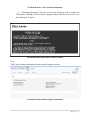
OPERATIONSMANUAL StatefulTrafficGenerator® STG‐10G 11January,2014 FOR TECHNICAL SUPPORT CALL: East Coast Datacom, Inc. 245 Gus Hipp Blvd., STE #3 Rockledge, FL 32955 USA TEL: (800) 240-7948 or (321) 637-9922 FAX: (321) 637-9980 WEB: www.ecdata.com Manufactured by: East Coast Datacom, Inc. Manual PT # 214001 Rev - 1|P a g e SAFETY WARNING Always observe standard safety precautions during installation, operation and maintenance of this product. To avoid the possibility of electrical shock, be sure to disconnect the power cord from the power source before you remove the IEC power fuses or perform any repairs. PROPRIETARY NOTICE The information contained herein is proprietary to East Coast Datacom, Inc. Any reproduction or redistribution of this publication, in whole or in part, is expressly prohibited unless written authorization is provided by East Coast Datacom, Inc. WARRANTY NOTICE WARRANTIES: East Coast Datacom, Inc. (hereafter referred to as E.C.D.) warrants that its equipment is free from any defects in materials and workmanship. The warranty period shall be three (3) years from the date of shipment. E.C.D.'s sole obligation under its warranty is limited to the repair or replacement of defective equipment, provided it is returned to E.C.D., transportation prepaid, within a reasonable period. This warranty will not extend to equipment subjected to accident, misuse, alterations or repair not made by E.C.D. or authorized by E.C.D. in writing. PUBLICATION NOTICE This manual has been compiled and checked for accuracy. The information in this manual does not constitute a warranty of performance. E.C.D. reserves the right to revise this publication and make changes from time to time in the content thereof. E.C.D. assumes no liability for losses incurred as a result of out-of-date or incorrect information contained in this manual. 2|P a g e Contents Manufacturedby:......................................................................................................................................................1 EastCoastDatacom,Inc.....................................................................................................................................1 StatefulTrafficGenerator®,modelSTG‐10G...............................................................................................4 Login.......................................................................................................................................................................10 CommonSection...............................................................................................................................................12 Home......................................................................................................................................................................14 EndPoints............................................................................................................................................................15 Experiment..........................................................................................................................................................20 3.5.1Createanewexperiment..............................................................................................................20 Addanewflow.............................................................................................................................................22 Experimentflows.........................................................................................................................................27 ExperimentLogoptions............................................................................................................................28 Importanexperimentconfiguration..................................................................................................29 Openanexistingexperiment..................................................................................................................29 Startanexperiment....................................................................................................................................30 Analyzer................................................................................................................................................................33 AnalyzeExperimentReport....................................................................................................................34 Settings/Upgrade..............................................................................................................................................36 Boxconfiguration........................................................................................................................................36 Dateandtime................................................................................................................................................37 Troubleshooting...........................................................................................................................................38 Upgrade............................................................................................................................................................39 Administration..............................................................................................................................................40 About......................................................................................................................................................................41 Information....................................................................................................................................................41 3|P a g e Help....................................................................................................................................................................43 StatefulTrafficGenerator®,modelSTG‐10G. Description TheStatefulTrafficGenerator®,modelSTG‐10GisanembeddedCOTSplatformbasedona well know traffic generation engine, D‐ITG™1. STG‐10G is composed of a Graphical User Interface(GUI)thatwrapstheD‐ITG™engineandothertools. Using D‐ITG™, STG‐10G is capable of producing IPv4 and IPv6 traffic by accurately replicating the workload of current Internet or typical user applications. The platform supports 8‐Ports 10/100/1000 and 4‐Ports of 10GbE traffic generation managed via the easytouseGUIthat. TheD‐ITG™generationengineprovidesmanyinterestinganduniquefeatures.Thankstoit the STG‐10G is also a network measurement tool able to measure the most common performance metrics such as throughput, delay, jitter and packet loss at the packet level. Also,usingD‐ITG™,theSTG‐10Gcangeneratetrafficfollowingstochasticmodelsforpacket size(PS)andinterdeparturetime(IDT)thatmimicapplication‐levelprotocolbehavior.By specifying the distributions of IDT and PS random variables, it is possible to choose differentrenewalprocessesforpacketgeneration:byusingcharacterizationandmodeling results from literature, STG‐10G is able to replicate statistical properties of traffic of differentwell‐knownapplicationssuchasTelnet,VoIP‐G.711,G.723,G.729,VoiceActivity Detection,CompressedRTP‐DNS,networkgames. At the transport layer, the STG‐10G currently supports UDP, TCP, ICMP, DCCP, SCTP and soon to be released support for IGMP. Additionally an FTP‐like passive mode is also supportedtoconductexperimentsinthepresenceofNATs,anditispossibletosettheTOS (DS) and TTL IP header fields. The STG‐10G also supports Pcap files with an easy to use Pcapplayer. TheSTG‐10Gsupportstwomodesofpackettransmission.OnebeingtheStandardModefor realistictrafficsimulationallowingadjustabledatarates.TheTurboModeallowslinerate transmissionutilizingINTEL®DPDKdriverswithPcapfilescontaininganytypeoftraffic. The core traffic generation features of STG‐10G are provided by embedding the main componentsoftheD‐ITG™engine(ITGSend™,ITGRecv™,ITGLog™,ITGDec™).ITGSend™is the component responsible for generating time stamped traffic toward ITGRecv™. Exploiting a multithreaded design, ITGSend™ can send multiple parallel traffic flows toward multiple ITGRecv™ instances, and ITGRecv™ can receive multiple parallel traffic flows from multiple ITGSend™ instances. A signaling channel is created between each coupleofITGSend™andITGRecv™componentstocontrolthegenerationofallthetraffic 1http://traffic.comics.unina.it/software/ITG/ 4|P a g e flows between them. This allows the STG10‐G to generate a number of flows towards a singleSTG‐10G,ortowardsdifferentSTG‐10Gatthesametime. ITGSend™ and ITGRecv™ can optionally produce log files containing detailed information abouteverysentandreceivedpacket.Thelogscanbesavedlocallyorsent–throughthe network–totheRemoteBox(s).TheITGDec™componentisinchargeofanalyzingthelog filesinordertoextractperformancemetricsrelatedtothetrafficflows.STG‐10Gallowsto easilycreate,storeandanalyzetheselogssothattheresultsareprominentlydisplayedin realtimeaschartsanddataresults,savedinalocallogfor viewingorexportedinatext formatforMatlab,OctaveorExcel. More information about D‐ITG™ are provided in the following. All the following features areprovidedbySTG‐10Ginasimpleandeasy‐to‐usefashion. ITGSend™:SenderComponentoftheD‐ITG™Platform TheITGSend™componentisresponsibleforgeneratingtrafficflowsandcanworkintwo differentmodes: 1)Single‐flow‐readtheconfigurationofthesingletrafficflowtogeneratetowardasingle ITGRecv™instancefromthecommandline; 2) Multi‐flow ‐ read the configuration of multiple traffic flows to generate toward one or moreITGRecv™instancesfromascriptfile.Thescriptismadeofalineforeachtrafficflow, whichincludesasetofcommand‐lineoptionsasinthesingle‐flowmode. EverytrafficflowgeneratedisdescribedbytwostochasticprocessesrelatingtoPacketSize (PS)andInternetDepartureTime(IDT),throughwhichwelldefinedtrafficprofilescanbe generated, emulating application protocols such as VoIP, DNS, etc.. PS and IDT series can alsobeloadedfromafileforeachflow.ITGSend™canloginformationabouteverysentor received packet, when running in One Way or Round Trip mode respectively. In the first 5|P a g e case,timestamps(andotherinformation)ofsentpacketsarestored,whileinthesecond case,timestamps(andotherinformation)ofsentandreceivedpacketsarestored.Foreach flowthesourceIPaddresscanbespecified,whichisusefulformulti‐homedhosts. ITGRecv™:ReceiverComponentoftheD‐ITG™Platform The ITGRecv™ component is responsible for receiving multiple parallel traffic flows generated by one or more ITGSend™ instances. ITGRecv™ normally runs as a multi‐ threaded daemon listening on a TCP socket for incoming traffic reception requests. Each timearequestisreceivedfromthenetwork,anewthreadiscreated,whichperformsall theoperationsrelatedtothenewrequest(e.g.receivingthepacketsoftheflow).Theport numbersonwhichSTGRecvwillreceiveeachflowandanyloggingactivityrequiredonthe receiversidecanberemotelycontrolledbyITGSend™.Aspecificsignalingprotocol,called TSP™,allowsITGRecv™andITGSend™toproperlysetupandmanagethetrafficgeneration process. ITGLog™:LoggerComponentoftheD‐ITG™Platform The ITGLog™ component embeds the ITGLog™ and it is responsible for receiving and storingloginformationpossiblysentbyITGSend™andITGRecv™.ITGLog™runsasamulti‐ threadeddaemonlisteningonaTCPsocketforincominglogrequests.Loginformationis received over TCP or UDP protocols on port numbers dynamically allocated in the range [9003–10003]. ITGDec™:DecoderComponentoftheD‐ITG™Platform The ITGDec™ component embeds the ITGDec™ and it is responsible for decoding and analyzing the log files stored during the experiments. ITGDec™ parses the log files generated by ITGSend™ and ITGRecv™ and calculates the average values of bitrate, delay and jitter either on the whole duration of the experiment or on variable‐sized time intervals.ITGDec™analyzesthelogfilesproducedbyITGSend™,ITGRecv™,andITGLog™in ordertoproducethefollowingresultsabouteachflowandaboutthewholesetofflows: – SyntheticreportsExported: o Experimentduration o PacketstransferredandReceived o Payloadbytestransferred o Round‐tripdelay(minimum,maximum,average,standarddeviation) o Averagebitrate o Averagepacketrate o Droppedpackets o Duplicatepackets o Lossevents o Averageloss‐burstsize o First/lastsequencenumber – SampledQoSmetricstimeseries: o –PacketSent/PacketsReceived o –Bitrate[Mbps] o –Round‐tripDelay[ms] 6|P a g e o –Jitter[ms](i.e.delayvariation) o –Packetloss[pps](i.e.packetslostpersecond) D‐ITG™Features D‐ITG™isabletogeneratemultipleunidirectionalflowsfrommanysenderstowardmany receivers,eachofthemhavingthefollowingfeatures. – Customizableflow‐levelproperties o duration o startdelay o totalnumberofpackets o totalnumberofKBytes – SupportedLayer‐3features o protocols:IPv4,IPv6 o customizableheaderfields: *sourceanddestinationIPaddresses *sourceinterfacebinding(formulti‐homeddevices) *initialTTLvalue *DSbyte o NATtraversal:FTP‐likepassivemode – SupportedLayer‐4features o protocols:TCP,UDP,ICMP,DCCP,SCTP o customizableheaderfields: *sourceanddestinationportnumbers – SupportedLayer‐7features o Predefined stochastic PS (Packet Size) and IDT (Inter Departure Time) profiles: *Telnet *DNS *Quake3 *CounterStrike(activeandinactive) *VoIP(G.711,G.729,G.723) o Payloadcontent:randomorreadfromfile o StochasticprocessessupportedforbothPSandIDT: *SupporteddistributionsareUniform,Constant,Exponential,Pareto, Cauchy,Normal,Poisson,Gamma,Weibull *Explicitrandomseedselectionforreplicatingthesamestochasticprocess *LoadingofPSandIDTseriesfromfile – Packet‐levelQoSmetrics o Bitrate o Packetrate o Onewaydelay(requiresFutureclockssynchronization) 7|P a g e o RoundTripTime o Jitter o Packetloss STG®Features TheSTGWebUserInterfacecomponent(referredinthisguidealsoas“theComponent”or as“WebUI”)isdesignedto: managethenetworkconfigurationofthedevice; allowthetrafficgenerationtolocalorremotedevices; receivethetrafficgenerationfromlocalorremotedevices; allowtheusageoftheproductforapre‐definedtrialperiod. ThisguideisaddressedtothegenericuseroftheComponentandprovidesinstructionson howtouseitonceinstalledonacompatiblehardwaredevice(hereafter“Box”). TheSTG‐10GGraphicalUserInterface(GUI)presentstheuserwithSixmaintabs. Howtheboxworks: 1)Hometab‐thistabworksasthebrowserHomebuttonsshould.Backtothebeginning! 2)End Points tab‐ for managing Local and Remote box LAN addressing. Managing the ControlPortforBoxtoBoxcommunicationsandExportingLocalconfigurationsforremote boxImportofLANportsettings.Thisallowstheusertoeasilyset‐upmultipleboxesand savetheboxEndPointconfigurations. 3)Experimentstab‐forcreatingorimportingnamedexperimentsandselectingStandard Mode to replicate stochastic modeling or Turbo Mode, which supports replay of any Pcap filetraffictypeatLineRates.TheuserthencreatesasingleFlowormultipleflowswithin 8|P a g e anExperiment.TheFlowscreenallowstheusertoNameeachFlow,definetheDuration, EndPoints,Protocol,PayloadSize,BandwidthorPacketsPerSecondrate.Theuseralsohas the option of loading a Pcap file in the Flow and defining Cyclic Repetitions and Speed Scaling for playback. Many other options are also available such as Payload Size Distributionmethod,InterDepartmentTimeDistribution,PacketstoGenerate,Kilobytesto Generate,aMeterforRoundTriporOnewaystatisticalcollection,TTLandseveralother optional user defined settings. When the Flow settings are complete, the user clicks Save Flow. NOTE:OneWayMeterstatisticsareretrievedquicklytotheuser,whilelargeexperimentssettoRoundTripMetercan resultinlargestatisticalfileswhichcanbetimeconsumingtoretrievedependingontheLogOptions. AnoverviewscreennowdisplayseachtheentireExperimentshowingeachFlowandthe maincharacteristicoftheFlow(s). NowtheusersselectoneorbothoftheLogOptionsforstatisticalcollection: A)Local‐LogGenerationSenderSide B)Remote‐LogGenerationReceiverSide NOTE:localLogstatisticsareretrievedquicklytotheuser.SelectingLocalandRemotewithlargeMulti‐Flowexperiments canresultinlargestatisticalfileswhichcanbetimeconsumingtoretrieve. AftertheuserhasdefinedallFlowsandLogOptionstheuserSavesthewholeExperiment and begins the Experiment by clicking Start. As the Flow(s) are beginning, a status bar appears on the users monitor indicating the progress. Upon completion, the statistical resultsaredisplayedaswellasgraphsforeachFlow.Theresultsmaybesavedforviewing intheAnalyzertaborsimplycanceled. 4)Analyzertab‐forretrievingthefinalsavedExperimentresults.Theresultsaresaved withExperimentName,DatetheLogoptionsasLocalorRemote.TheLogFileresultsmay beadjustedbySamplingRateTimeforfurtherviewingorExported.Theexportfileisone packetperlineandallowsexaminationinMatlab,Octave,Excelect... 5) Settings/Upgradetab‐ThistaballowstheusertosettheboxName,DateandTime, Submit Trouble shooting Reports, Enable Remote Support (paid subscription), System FirmwareUpdatethatrequiresKeyCodesandmanagingtheallimportantAdministration Port. 6)Abouttab‐theabouttabcontainsthetwosections; A) Information ‐ selection which allows the user to view the current Box Information, InstalledComponentsandLicensingInformation.Theseincludethesoftwarerevisionlevels and open source codes contained in the STG‐10G. This also includes an activation key shownasFullor30Days. B) Help ‐ selection that allows the user to contact Technical Support for the box and a holderforthesoontobereleasedUserManual. AlsoincludedareaLogOutbuttonwhichhasanadditionalfunctiontoResettheSTG‐10G hardwarebox.AswelltheRefreshbuttonthatmaybeusedwithintheSTG‐10Gsystemto repaintascreen. 9|P a g e Conventions Inthisguidethenamesoffiles,utilitiesandcommandsthataremeanttobewrittenas‐is arerenderedwithfixed‐sizefont,e.g. filename.php UsageInstructions ThissectiondescribeshowtheWebUIismadeup,howyoucanuseeachcomponents. Login Once the Component is activated, you can launch WebUI in your browser connecting to http://192.168.50.1whereyouwillseethe“LoginPage”thatshows: aninputboxtoinserttheusername; aninputboxtoinsertthepassword; thebutton“Signin”tosendthecredentialtologinthebox. thebutton“Recovery”tochangethepasswordofthebox. 3.1Loginform. If the username or the password is wrong, a message is displayed notifying the error, as showninthefollowingfigure. 10|P a g e 3.2Errormessageofcredentiallogin. Incaseyouforgetthepasswordyoucanretrieveitusing“Recovery”button.Thisoperation canbedoneonlyconnectingyourhosttotheboxusingtheadministrationport(ontheIP address 172.17.71.2), configuring your network device with the 172.17.71.2 IP address. Thispreliminarystepisessentialtodisplaythescreentochangethecredentialotherwise thefollowingerrormessagewillbeshown: 11|P a g e 3.3Errormessageofpasswordrecovery. The second step consists of inserting the new password twice to avoid typing errors as shownbelow: 3.4Passwordrecoveryform. CommonSection Afterloginstep,thepageconsistsofthreeparts: header,whichisdescribedinthissection; body,analyzedindetailsinthefollowingsections; footer,thatshowsproducerinformation. 12|P a g e 3.5WebUIStructure. HeadersectioniscommonforallWebUIpages. 3.5WebUIHeader. It presents the East Coast Datacom logo, the name of the product (Stateful Traffic Generator) and the generator type, 1G or 10G, according to the hardware capability. The centralareaisusedtoshowthenotificationmessageswhichcanbe: information message: used to notify any information message (it automatically disappears); errormessage:usedtonotifyerrororalert(ithastobeclosedmanually); successmessage:usedtonotifyoperationsuccessfullyfinished(itautomatically disappears). 13|P a g e 3.6Notificationmessages. Ontherightofheadersectiontherearethenameofthelocalboxandthe“Logout”button toexitfromtheComponent. The last part of header is the menu which allows you to navigate in WebUI subsections, analyzedinthefollowingsections: Home EndPoints Experiment Analyzer Settings/Upgrade About Home Homepagegivesabriefandquicktutorialonhowtostartanexperiment.Followingallthe steps,infact,youwillbeabletoconfigurethenetworkconfigurationofyourbox,createan experiment,executeitandanalyzetheresults. 3.7WebUIHomepage. 14|P a g e EndPoints “EndPoints”ismadeupoftwomainlysections: Localboxinformation,containingthenetworkconfigurationsofthelocaldevice. Remote boxes information, containing the network configurations of the boxes towhichgeneratetraffic. Thefollowingfiguregivesanoverviewoflocalboxsection.Inparticular,intheheadofthis subsection you can configure information about “Control TCP Port”, that is the signaling channelportnumber,andthe“DefaultGateway”. 3.8WebUIEndPoints:LocalBoxconfiguration. Tomodifythemyoushouldclickonthewheelbuttonthatwillenablethefieldsforediting. Twobuttonswillbeshown,greenandredones,forsavingordiscardingthechanges. 3.9WebUIEndPoints:ControlTCPPortandDefaultGatewayconfiguration. Theorangebutton“Export”,onthetop‐leftsideinthefigure3.8,allowstoexportnetwork configurationofthelocalbox.Clickingonit,adialogwillbeopenedandyoucanselectthe IPaddressesyouwanttoexport.Theexportconfigurationconsistsof: localboxname,whichiscustomizableinthe“Settings/Upgrade”page; ControlTCPPort; oneControlIPaddress(aremoteboxcanhaveonlyoneControlIPaddress); zeroormoreDataIPaddress. 15|P a g e 3.10WebUIEndPoints:Exportlocalboxconfiguration. The last section of local box area consists of a table for managing the entire network configurationoflocalhost.Therearetwotypesofnetworkinterfaces:thecontrolinterface (inblue)isusedasthesenderordestinationaddressforthesignalingchannelbetweenthe boxes,anddatainterfaces(inyellow)areusedforthesenderanddestinationaddressesfor theprobingtraffic. Eachinterfacehasinformationabout: connectionspeed; connectionstatus:“linkup”or“linkdown”,whichmeansifitisconnectedornot; dhcp,whichallowstoobtain,ifcheckboxisenabled,theIPaddressfromaDHCP client; IPaddressesandnetmasksrelatedtothisinterface. 3.11WebUIEndPoints:Networkconfigurationoflocalbox. The connection speed can be modified clicking on the wheel button of the first row of interface area. It is possible to specify “Autonegotiation”, that enables device to automaticallyexchangeinformationoveralinkaboutspeedandduplexabilities,oryoucan 16|P a g e chose between the speeds supported by the interface (i.e. 10 Mbit/s, 100 Mbit/s or 1Gbit/s). 3.12WebUIEndPoints:modifyinterfaceinformation. The DHCP checkbox, if enabled, allows to the interface to contact the DHCP server to obtain, dynamically, an IP address (this step assumes there is a DHCP server in the network). If DHCP field is disabled you may specify statically IP Address version 4 and netmask(theIPAddressversion6isallowedonlyfordataaddresses). The green and red buttons, that have replaced the wheel button, allow you to save or discardtheconfigurationchanges. An interface may have related zero or multiple IP addresses. If it has no associated IP address,itisdefined“notassigned”.BesidesiftheIPaddressisdefinedbyuseritwillbea static address and it has wheel button for editing and trash button for deleting. If the IP address is generated by device it has no button because it can neither be modified nor deleted. Itisimportanttonotethatintheexperimentconfigurationsteponlytheinterfaceswithat leastoneassociatedIPaddressareconsidered. The second section of “End Points” page regards the network configuration of remote boxes,thatarethedevicestowardwhichtogeneratetraffic. 3.13WebUIEndPoints:Remoteboxessubsection. The top area shows three buttons. “Add box” button allows to add a new remote host inserting amnemonicname of box (which can differ from real boxname), theControl IP addressandtheTCPPort,asshowninthefigure3.14. 17|P a g e 3.14WebUIEndPoints:addanewremotebox Clicking on the green button on the right side of the row, the inserted information are stored. To evaluate if the IP address and port are reachable is used the PING utility, so you have different cases: IPaddressunreachable; IPaddressreachable: TCPPortreachable; TCPPortunreachable. 3.15WebUIEndPoints:reachabilityofIPaddressandTCPport. Itisimportanttoknowthattheremoteboxaddressesarenotsynchronizedautomaticallywiththe referredSTGbox. “Export”button,similarlyto“Localbox”section,allowstoexportthesectionconfiguration.Infact, clickingonbutton,thefollowingdialogappearswhichshowsalistofallconfiguredremotedevices. 3.15WebUIEndPoints:exportremoteboxesconfiguration “Import”buttonallowstouploadtheconfigurationofaboxormultipleboxes,choosingthe exportedfilefromlocalorremotesections. 18|P a g e 3.16WebUIEndPoints:importremotebox(es)configuration Theimportedremotebox(orboxes)willbeappendtotheremoteboxestableormergedto existingboxwheretheboxnamearethesame. RemoteboxestableshowsalistofremotedevicesconsistingofonecontrolIPaddressand oneormoredataIPaddresses,eachofthemcanbemodifiedordeletedusingthebuttons ontherightside. 3.17WebUIEndPoints:edit,deleteandaddadataIPaddressofaremotebox Tomodifythenameofaremoteboxyoucanpushthewrenchbuttonplacedonthebottom of remote box name. After editing the name in the input field you must push on green button or red button to save or discard the change (as shown in the right image of the figure3.17). Todeleteaboxyoucanusetrashbutton,placedonthebottomofremoteboxname. “Add data port” button allows you to add a new data IP address to the related remote device. As previously shown for local box, and pointed out in the following figure, a new row is appended to the box and an IP version 4 or 6 can be inserted. The green and red buttonontherightsideallowsyoutosaveordiscardtheIPaddress. 3.18WebUIEndPoints:adddataIPaddresstoaremotebox IfyouwanttomodifyanIPaddressyouwillpushonwheelbuttonplacedontherightsideofeach IPaddressrow,whiletheredtrashbuttonwillallowyoutodeletetherelatedaddress. 19|P a g e Experiment “Experiment”pageisdividedintwosubsection: leftsubsectionallowsyouto: createanewexperimentclickingon“Create”button; importanexperimentclickingon“Import”button; rightsubsectionlistsallsavedexperiment,whichcanbereopenedordeleted pushingontherelatedbuttonontherightside. 3.19WebUIExperiment:management 3.5.1Createanewexperiment Afterclickingon“Create”buttonanewpageisopened,showninthefollowingfigure3.20. Thispageconsiders: aninputfieldforinsertingexperimentname; a select field for choosing the experiment operating mode, Standard or Turbo, whichisbetterexplainedlater; fourbuttonsto: o save the experiment name and, in a second step, the experiment configuration; o deletetheexperimentandallitsresults; o closethecurrentexperiment,returningonthepreviouspage; o exporttheexperimentforusingitonotherSTGbox; asubsectioncontainingtheexperimentdetails,analyzedindetailslater. 3.20WebUIExperiment:createanewexperiment Once set the experiment name “Save” button becomes clickable to store it, enabling the subsection to add other experiment configurations. In fact, after this operation, the subsectionappearsasinthefollowingfigure. 20|P a g e 3.21WebUIExperiment:configuretheexperiment Ifyouwanttomodifytheexperimentnameyoumustpushonthewheelimagehighlighted inredinthefollowingfigure.Thisactionwillbeappearaneditablefieldfromwhichyou canmodifythename.Tosaveit,youhavetopushthecheckmarkbutton 3.22WebUIExperiment:changeexperimentname . Thesubsectionconsistsof: “Start”buttonallowsyoutoexecutetheexperiment.Itisdisabledwhenthe experimentconfigurationhasnoflow. “Live report” checkbox allows you to show real time analysis during experiment execution. Besides, enabling it, you can choose one or more parameter among delay, jitter, bitrate and packet loss you want to analyze and a graph checkbox if you want to see or not the graph during the experimentexecution. “Addnewflow”permitstoopenadialogforcreatingaflow.Thiswindowis explainedbetterinthefollowingsubsection. “Analyze”buttoncross‐refertoanalyzesectionofexperimentresults, The middle of this subsection is reserved for the configured flows. Initially thereisnoflowaddedtotheexperiment,soaninfomessageisshown. The last area regards the “Log options” configuration, which is explained later. 21|P a g e Addanewflow Pushingonthe“Addnewflow”button,thefollowingdialogwillbeopenedtoconfigurea flow.Inthissectionitsfunctionalitieswillbeexplainedindetails. 3.22WebUIExperiment:flowconfigurationwindow The“Name”fieldisamnemonicnamethatallowstogiveacustomnametotheflow.Itis not important for the experiment purposes but it may be helpful to recognize the flow whenanalyzingtheexperimentresults. “Local Control Address” field allows to configure the source address for the signaling channel.Youcanselect“Auto”,leavingthetaskofchoosingthebestaddresstousetothe operatingsystem,oranyControlIPaddressesofLocalBoxconfiguredinthe“EndPoints” section. “Loopback”fieldallowstogeneratetraffictowardthesamelocalbox.Ifenabled,infact,the “RemoteBox”fieldisdisabled. 22|P a g e “Remote Box” field regards the hosts toward which you want to send the traffic. You can chooseoneoftheremoteboxesconfiguredinthe“EndPoints”section,defininginthisway theIPaddressofthedestinationsignaling. The“Customflow‐leveloptions”greensectionregardstheconfigurationofinitialandfinal delay, the generation duration, the number of packets and the number of KBytes to generateandthemeter(seetheD‐ITGmanual2formoreexplanations).Itisimportantto noteyoucanchooseonlyoneparameterbetweenduration,packetsandKBytenumberto generate,infactsettingoneofthethreevaluesyoucannotspecifytheremainingothers. Besidesyoucanloginformationabouteverysentorreceivedpacket,whenrunningin“One Way” or “Round Trip” mode respectively, by using “Meter” option. In the first case, the timestamps(andotherinformation)ofsentpacketarestored,whileinthesecondcase,the timestamps(andotherinformation)ofsentandreceivedpacketsarestored. The “Data options” yellow section regards the configuration of packets and it consists of twosubsection: “Header options”, which gather information about level 3 and 4 of TCP/IP stack; “Applicationoptions”whichincludesapplicationlevelinformation. In the “Header options” the choices depend on what you have selected in the first configurationstep,ifloopbackorwhichremotehost.Ifyouhaveselectedloopbackmode youwillseethefollowingfields: 3.23WebUIExperiment:loopbacksourceanddestinationdataports The first of them, “Loopback Source Data Port”, allows you to select the sender Data IP Address,whilethelatter,“LoopbackDestinationDataPort”,representstheDataIPAddress towardwhichthetrafficisgenerated.Thefieldshowstheinformationabouttheinterface (i.e.Dataport#1andDataport#2)andtheIPAddressthatcanbeonlyanIPversion4,as showninthe“L3Protocol”field.Anotherrestrictionisyoucannotselectthesameinterface forbothdataports,infacttheinterfacethatisselectedinthesourceportdoesnotappear inthedestinationfield. Ifinthefirstconfigurationstepyouchosearemoteboxinsteadofloopbackyouwillseethe followingoptions: 3.24WebUIExperiment:localandremotedataports 2http://traffic.comics.unina.it/software/ITG/documentation.php 23|P a g e “Local Data Port”, as said before, lists all data ports configured in “End Points” section, instead“RemoteDataPort”listsalldataportsrelatedtotheselectedRemotehost.Inthis caseyoucanchooseIPversion4or6.AlsointhiscasethereistheIPversionrestriction: theIPversionselectedby“LocalDataPort”imposestherelatedversionto“RemoteData Port”. In the “TTL” field you may specify the IP Time To Live, which by default is 64, while in “TOS”fieldregardstheTypeofServiceheadervalue. “L4Protocol”liststheprotocoltypeyoucanusefortrafficgeneration: UDP,UserDataProtocol; TCP,TransmissionControlProtocol; ICMP,InternetControlMessageProtocol; DCCP,DatagramCongestionControlProtocol; SCTP,StreamControlTransmissionProtocol. ForUDP,TCP,DCCPandSCTPprotocolyoucanchoosethesourceanddestinationport.In addition,forthelastprotocolyoumayspecifytheassociationIDandSCTPsessiontoo.For ICMP protocol, instead, you can specify the Type number, which by default is 0 (Echo Reply).NotethatifyougenerateICMPechorequestmessages(type8),youwillsolicitecho repliesfromtheoperatingsystemoftheremotebox. “ApplicationOptions”configurationhastwooperatingmode: “synthetic”modegivesyouthepossibilitytoconfigurethestochasticmodels for packet size and inter departure time that mimics application‐level protocolbehavior. “pcap”modeallowsyoutousepcaptracecontainingrealtraffictogenerate networkworkloadwithmoresemanticvalue. Inthefirstmode,“SyntheticMode”,itispossibletochoosedifferentrenewalprocessesfor packet generation. Through “Predefined Stochastic Profile” and by using characterization andmodelingresultsfromliterature,youcanreplicatethestatisticalpropertiesoftrafficof differentwell‐knownapplications: “Telnet” option emulates Telnet characteristics. It works only with TCP transportlayerprotocol. “VoIP” option emulates Voice‐over‐IP traffic and you can select the audio codec type between G.711 and G.723 or G.729, the audio transfer protocol between RTP or CRTP and enabling or not the Voice Activity Detection. It onlyworkswithUDPtransportlayerprotocol. “DNS” option emulates DNS traffic. It works with both UDP and TCP transportlayerprotocol. Network games option like “Quake3” or ”CounterStrike” (active or idle phaseofthegame).TheyonlyworkwithUDPtransportlayerprotocol. 24|P a g e It is possible to generate traffic according to the different configurations of packet size, packetrateandbandwidth. Thebandwidthdependsonbitratevaluethatcanbeapredefinedorcustomizedvalueat mostequaltotheselectedinterfaceconnectionspeed. Thepacketsizedependsonpayloadsizeandonheadersize(whichchangesaccordingto thenetworklayerprotocolandtransportlayerprotocol).Itcanbe: apredefinedvalue; calculatedfromanuploadedfile; avariablevaluebasedonpayloadsizedistribution: ○ Constant; ○ Uniform; ○ Exponential; ○ Pareto; ○ Cauchy; ○ Normal; ○ Poisson; ○ Gamma; ○ Weibull. ThepacketratedependsontheInterDepartureTime(IDT),thatisthetimebetweenthe transmissionoftwosuccessivepackets.Itcanbe: apredefinedvalue; calculatedfromanuploadedfile; avariablevalueaccordingtotheIDTdistribution: ○ Constant; ○ Uniform; ○ Exponential; ○ Pareto; ○ Cauchy; ○ Normal; ○ Poisson; ○ Gamma; ○ Weibull. ○ Foreachdistributionyoumustinsertthecharacterizingparameters(oneortwoaccording to the distribution type) and the resulting packet rate and packet size values assume a statisticalmeaningintermsofmeanormedian,asshownintherelatedread‐onlyfield. Besides, the packet rate and bandwidth values influence each other. Therefore, once you have set the packet size, setting also the packet rate, the bandwidth value will be automaticallycalculatedwhile,ontheotherhand,ifyousetthebandwidthvaluethepacket ratewillbesubsequentlyadapted. 25|P a g e Inanycase,ifyouchooseapredefinedstochasticprofileoracustomprofile,youcansetthe seed value for generating distribution and the payload content that can be generated in randommodeorreadfromfile. Thesecondwaytoconfigurethe“Applicationoptions”,assaidbefore,isthe“PCAP”mode asshowninthefollowingfigure. 3.25WebUIExperiment:PCAPmode Initially,ifyouareconfiguringthefirstexperimentflow,therearenouploadedPCAPtrace youcanchooseso,afterselectingthePCAPfileonyoursystem,youcanuploaditpushing onthebutton .Theuploadedfilewillbeanalyzedaccordingtotheselectednetwork and transport layer protocols (in “Standard” Experiment you can choose UDP or TCP protocol,whilein“Turbo”experimentthereisnofilterbasedonL4protocolandthewhole traceisselected)andinablackscreenitwillbeshownthefilteredPCAPtraces. 3.26WebUIExperiment:PCAPtrace In each row there is the source address and port, the destination address and port, the frameandbytenumbersgeneratedintheconversationfromthedestinationtothesource addresses, in the opposite side and in both direction, the relative start time and the durationoftheconversation. In“Standard”experimentyoucanchoosethePCAPConversationthatyouwanttousefrom therelatedselectfield.Thischoiceimpliesthemodificationofsourceanddestinationports. Besides, specifying the “Cyclic Repetition” and the “Speed Scaling” you can replicate the selected PCAP conversation using a scale factor with which multiplies the IDT value. The resultingtotaldurationissetinthe“Duration”fieldin“Customflow‐leveloptions”. IfyouhavealreadyuploadedaPCAPtracefile,the“Applicationoptions”sectionshowsyou a select field with each file. So you can choose one of them or upload a new file as said before. 26|P a g e 3.28WebUIExperiment:PCAPtraceselection Theflowconfigurationendsclickingon“Add”buttoninthefooterofdialogwindow. Please remember to save the experiment after adding a flow in order to save the flow information!! Experimentflows Afteraddingyourfirstconfiguredflow,the“Experiment”pageshowssyntheticinformation aboutitasshowninthefollowingfigure: 3.29WebUIExperiment:flowsconfigurationsoverview Therowisdividedinmultiplecolumn: thefirstcolumnshowstheflowname,thesourceportandthedestinationbox (orthedestinationportifyouchose“Loopback”option),thesourceaddressand portand,finally,thedestinationaddressandport; thesecondcolumnshowsthetransportlayerprotocol; thethirdcolumnisabouttheStochasticProfile; thefourthcolumnconcernsthepayloadsize(hencetherelatedpacketsize); thefifthcolumn,instead,showsthepacketrateandIDTconfiguration; thesixthcolumnisaboutthebandwidthvalue; theseventhcolumnshowsthedurationtime; theeighthcolumn,whichishiddenbydefault,containsthedelay; thelastcolumnincludesfourbuttonto: ○ enable or disable the flow that means to generate the traffic when experimentwillbeexecuted; ○ exporttheflowsoitcanbeimportedonanotherexperimentbox; ○ edittheflowconfiguration 27|P a g e ○ deletetheflowconfiguration. You can use the command from the second to the eight column to modify on the fly the singleflowconfiguration. IftheflowhasconfiguredinPCAPmodetherowcontainsdifferentinformation,infact,as showninthefigure3.30,theyassumethefollowingmeanings: thesecondcolumngivesmodeinformation; thethirdcolumnthenameofthePCAPfile; the fourth column is about the number of packets and byte that are be generated from source to destination, i.e. upstream, and, if you chose bidirectional mode, the downstream traffic generation, from destination to source. 3.30WebUIExperiment:PCAPflowconfigurationoverview ExperimentLogoptions The“Logoptions”showninthefigure3.31allowsyoutoenablethetrafficloggingoptions bothsenderandreceiverside.Thisscreenisdividedintotwoboxes: LocalEndPoint; RemoteEndPoints. Foreach ofthem you can choosethedestinationbox,whichcanbethelocaloraremote host,andthetransportprotocoltypeinthelastcase. Please note that the log is necessary to obtain the performance measures (bitrate, jitter, etc.). The log can be disabled in case it is only necessary to generate the traffic without beinginterestedintheperformancemeasures. 3.31WebUIExperiment:Loggerconfigurationin“Standard”experiment 28|P a g e IntheTurbomodeyoucanchooseonlythesamplingrate. 3.32WebUIExperiment:Loggerconfigurationin“Turbo”experiment Importanexperimentconfiguration Asshowninthe3.19figure,toimportanexperimentyoumustselectafileandpushonthe “Import” button. After uploading you find it in the right experiment list. The following figureshowsthetwostep. 3.33WebUIExperiment:importexperimentconfiguration Openanexistingexperiment An experiment can be opened pushing on the related button of one of the items of the experimentslist,showingtheexperimentdetails. If one of the experiment flows has incoherent information compared to the box configuration(i.e.EndPointsconfiguration)theflowwillbedisabledanditsnamewillbe coloredinred,asshowninthefollowingfigure. 3.34WebUIExperiment:flowconfigurationdisabled Inthiscaseyoumustedittheflowconfigurationandsolvetheproblembeforeenablingit. 29|P a g e Startanexperiment Oncetheexperimentconfigurationisfinishedyoucanstartthetestpushingonthe"Start" button.Thisactionwillopenthefollowingdialogbox. 3.34WebUIExperiment:experimentexecution Theexperimentexecutionconsistoffourstep: 1. “Preparingexperiment”:lockallselectedboxesusedasreceiverorlogger; 3.36WebUIExperiment:experimentexecution‐“Preparingexperiment”step 2. “Experiment in progress”: prepare the execution of the test, copying if necessary PCAPtracesontheremoteboxes. 3.37WebUIExperiment:experimentexecution‐“Experimentinprogress”step andruntheexperiment(abarwillshowitsprogress); 3.38WebUIExperiment:experimentexecution‐“Experimentinprogress”step 30|P a g e 3. “Retrievinglogs”:retrievethesenderandreceiverlogsfromlocalorremoteboxes inaccordingtotheloggerconfigurations; 3.39WebUIExperiment:experimentexecution‐“Retrievinglogs”step 4. “Generating report”: if you have chosen to log at the sender side, on the local box youwillseethereportoftheexecutedtest. 3.40WebUIExperiment:experimentexecution‐“Generatingreport”step Oncethereportissuccessfullydecodedyouwillseetheexperimentresults. 31|P a g e 3.41WebUIExperiment:experimentexecution‐“Generatingreport”step Attheendoffourthstepan“autosave”timerwillstart.Itcanbedisabledpushingonthe relatedcheckboxfield. 3.42WebUIExperiment:experimentresultautosave Youcanmanagetheexperimentexecutionusingthebuttonsplacedtothebottomofdialog window,asshowninthe3.43figure. 3.43WebUIExperiment:experimenttestbuttons 32|P a g e Thebuttonshavethefollowingtasks: “Stop”:interruptsthetestexecution.Onlypartialdataoftheexecutedtestwill beanalyzable. “Abort”:ifthereisapendingtestitwillstopitsexecutionanditdiscardsthe obtaineddataanyway. “Save and exit”: allows to save the result of the executed test and return to flowsconfigurationpage.Allthesavedresultsarevisiblein“Analyzer”page. “Discard”:discardstheexperimentresults. Thefirsttwobuttonsarevisibleduringtheexperimentexecutionwhilethelastonesatthe endoftheexperiments. Analyzer “Analyzer” section allows you to evaluate the experiments report. It consists in two sections: “Logs” section is a navigable tree of all configured experiments. In the first step you can choose the experiment by its name, viewing all the experiment date in whichtheyareexecuted.Selectingoneofthemyouwillchoosethelogreportthat youwanttoanalyze,senderorremoteone. “Report parameters configuration” allows you to set the “Sampling time” and which parameter you want to evaluate in the report. You can select all or a combinationofthefollowingparameters: ○ delay; ○ jitter; ○ bitrate; ○ packetloss. 3.44WebUIAnalyze:anoverview “Showreport”buttonhavetwofunctionalities: pushingonthebutton(ontheleftside)itshowsthereportinthesamepage; pushing on the caret on the right side of button you can show only the report sectioninablankpage. 33|P a g e AnalyzeExperimentReport The following figure shows the report of the selected log file of the experiment. In the headerthereare: the“Back”buttontoreturnthepreviousscreen; the “Export Octave/Matlab Log” button to download the export results in the “MAT”formattoloadtheminOctaveorMatlabsoftware; theexperimentnameandtheexecutiondateofthetest. Thenextsectionisabout“Experimentsummary”thatresumes: thetotalnumberofflowsinvolvedintheexperimenttest; thetotaltime,insecond,usedtoexecutethetest; thedelaystandarddeviation,inmillisecond; theaverageloss‐bustsize,inpacketsnumber. Other specific information about the experiment test are shown in the section “Per‐flow results”,inwhichthereisatableconsistingarowforeachexperimentflowand,thelast,an aggregate of flows values. The table columns are been categorized in four macro‐ information: packets:thenumberofpacketswillbeinvolvedinthetest,thatcanbe: ○ TX,sentpacketsfromsourcetodestination ○ RX, received packets from source that will be sent from the destination. In thecaseof“oneway”test,theyassumesasvalue0. delay:inmilliseconds ○ minumum ○ maximum ○ average jitter:inmilliseconds ○ minimum ○ maximum ○ average bitrate:inMegabitspersecond ○ minimum ○ maximum ○ average packetloss:inpacketspersecond ○ minimum ○ maximum ○ average. Eachcolumncanbehiddenusingthefiltermenuthatgivestoyouthepossibilitytoselect oneormoreinformation. The last section shows a graphs for every selected parameter of the aggregate flow information. 34|P a g e 3.45WebUIAnalyze:experimentreport 35|P a g e Settings/Upgrade The“Settings/Upgrade”pageconsistsofseveralsectionsaboutgeneralboxconfiguration. 3.46WebUISettings/Upgrade:anoverview Boxconfiguration In“Boxconfiguration”areayoufind: “Boxname”:thenameofthelocalbox. “Language”:thelanguageusedintheWebUI.Bydefaultitis“English”. “Session timeout”: how long a session is valid after which, if you do not refresh, submit or request information, it will expire and you will be redirected to the login page. It is important to note that if you close the browserapplicationsessionexpires. Youcanchangeoneofthesevalueandaftersaveitpushingon“Apply”button. 36|P a g e 3.47WebUISettings/Upgrade:boxconfiguration Dateandtime “Dateandtime”areaallowsyoutoconfigurethetimingofthelocalSTGbox.Youhavetwo configurationtype: manual configuration: you can specify the date, the time (hour and minute) andthetimezone. automatic configuration: you can synchronize your box using the Network Time Protocol (NTP) or choosing a remote box, as pre‐configured in “End Points”section.Theseoptionsarelistedin“Syncendpoints”selectfield. 3.48WebUISettings/Upgrade:dateandtime Itisimportantthesynchronizationamongsenderandreceiverboxesinordertocorrectly measurepacketonewaydelay.Ifyoucannotassurethis,wesuggesttousetheround‐trip timemeterwhenconfiguringtheflow. 37|P a g e Troubleshooting 3.49WebUISettings/Upgrade:troubleshooting “Troubleshooting”areaallowsyouto: “Enable remote support” (CURRENTLY NOT IMPLEMENTED) for giving the possibility to the support team to connect to your box. This field must be enabled if you want to add a new network card to the box, so Ecdata TechnicalSupportcanconfigureitcorrectly; “Generate debug output” (CURRENTLY NOT IMPLEMENTED) enables a popupwindowforshowingdebuginformation. Tosavethechangesyoumustpushon“Apply”button. “Submitbugreport”buttonallowsyoutosendortodownloadallbox configurationforbugreporting.Pushingonitthefollowingpopupwillbe opened. 38|P a g e 3.50WebUISettings/Upgrade:supportbugreport Inthiswindowyoucan: describetheobservedbug,attach,ifyouwant,animageorazippedfileand sending them by email to ECData support ([email protected]) using “Send” button; downloadtoyoursystemtheboxconfigurationpushingonthe“ExportBox Configuration”button. Upgrade “Upgrade”sectionallowstoupdateeachSTGcomponent.Afterchoosingthefileyoumust insertthe“Activationkey”thatiscomposedof5stringof5alphanumericcharacters. 3.51WebUISettings/Upgrade:upgrade 39|P a g e Pushingon“Apply”buttonadialogwindowwillpopupwiththechangelogoftheupgrade process. Now you can choose to install or abort the update process selecting the related buttons. Administration “Administration”sectionallowstomanage: thechangeofpasswordpushingon“Changepassword”button theDNSServerIPaddressusingthewheelbutton theadministrationportconfigurationusingthebluetableasshownin“End Points”chapter. 3.52WebUISettings/Upgrade:administration So, pushing on “Change password” button a popup, as shown below, will be opened, in whichyoumustinserttheoldandthenewpassword. 3.53WebUISettings/Upgrade:changeadministratorpassword 40|P a g e Pushing on wheel button, the “DNS Server” field will be enabled to modify the related IP address.Asshowninthe3.39figure,thegreenandredbuttonsallowyoutosaveordiscard thechangerespectively. 3.54WebUISettings/Upgrade:changeDNSServerIPaddress The“Routingtable”button,locatedontherightside,willshowapopupthatresumesthe informationaboutroutingconfigurationofthelocalbox. 3.55WebUISettings/Upgrade:routingtableconfiguration About The“About”menuitemconsistsof: Information Help Information “Information”pageisdividedintothreesub‐sectionasshowninthefollowingfigure. 41|P a g e 3.56WebUIAbout:informationoverview Thesubsectionsare: “Boxinformation”containing: o the“SerialNumber”ofthebox o the“BoxActivationKey” “Installedcomponents”listseveryinstalledcomponents,specifyingtheversion, the revision, the status (full or trial) and the details about expiry date. The “Install”and“Remove”buttonsallowsyoutomakeornotpermanenttherelated package. 42|P a g e 3.57WebUIAbout:“Trial”installedcomponent “Licensing information” lists the open‐source softwares used to realize the STGproduct.Pushingoneachofthemapopupwindowwillshowitslicense,asin thefollowing3.41figure. 3.58WebUIAbout:open‐sourcesoftwarelicense Help “Help”pagecontainsinformationabouttechnicalsupportcontact. 3.59WebUIAbout:technicalsupportinformation 43|P a g e