1
www.EmbeddedMarket.com
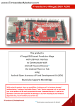
Embedded Engineer’s Development Tool 6.0
First time in the world,
One development board for
Five Microcontroller Families
AVR + 8051 + PIC + ARM + ARDUINO
with Programmers
Product Datasheet
1
www.EmbeddedMarket.com
Embedded Engineer’s Development Tool 6.0
Sr. Num.
Topics
Page
1
About EEDT 6.0
3
2
Microcontrollers included in EEDT6.0 product pack.
5
3
Microcontrollers supported by EEDT6.0.
6
4
Programmers included in EEDT6.0 product pack
7
5
List of accessories included in EEDT6.0 product pack.
8
6
Interface circuits mounted on EEDT6.0 board
9
7
Programming onboard AVR microcontrollers
10
8
Programming onboard P89V51RD2 & ARM microcontroller
14
9
Programming onboard PIC microcontrollers
18
10
Using onboard Arduino
19
11
Using EEDT6.0 hardware board
20
12
Important information
36
Product Datasheet
2
www.EmbeddedMarket.com
Embedded Engineer’s Development Tool 6.0
1. About EEDT 6.0
Embedded Engineer’s Development Tool (EEDT) is our oldest product offering.
It has evolved over last 5 years. Initially EEDT was designed for AVR and 8051 microcontrollers.
Later the PIC microcontrollers were supported.
Now EEDT6.0 completes most common microcontroller families by offering support to ARM and Arduino in addition to
classic 8051, AVR and PIC microcontrollers.
Arduino cannot be exactly classified as the Microcontroller Family. Arduino is most versatile Open-Source Physical
Computing platform based on AVR microcontrollers.
Since beginning of our EEDT product range, our emphasis was always on offering multiple microcontroller support on
single development board with variety of famous interface circuits. EEDT has always been a complete set of
development system. ISP Programmers, IDEs, Compilers, Sample Source Code, Cables, Connectors and power supply
were part of the standard packing. In export shipment, we do not include certain low cost – high weight accessories like
cables. Power supplies are also not included as every country has unique wall mounting sockets.
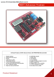
The EEDT 6.0 Development board includes following sections on the Board:
(Below sectional numbers are marked on the Hardware Board)
Sec -1]
Seven Segment Display - Four multiplexed
Sec–2]
Variable resistance for Analog Input – Three separate presets
Sec-3]
Pulled down Push to On Switches – Eight Switches
Sec-4-]
Pulled up Push to On Switches – Eight Switches
Sec-5]
Matrix keypad of 4x4 keys – Total Sixteen Keys
Sec-6]
I2C Based Real time clock, EEPROM & Digital to Analog Converter
Sec-7]
Mount here ATTiny13 and other Pin compatible AVR Microcontrollers
Sec-8]
Mount here PIC16F873A and other Pin compatible PIC Microcontrollers
Sec-9]
Mount here ATmega8 / ATmega168 and other Pin compatible AVR Microcontrollers
Sec-10]
Mount here PIC18F4550 / PIC18F452 and other Pin Compatible PIC Microcontrollers
Product Datasheet
3
www.EmbeddedMarket.com
Embedded Engineer’s Development Tool 6.0
Sec-11]
16x2 LCD Interface. LCD is mounted on the board. Same place can be used for 20x4 LCD
Sec-12]
Pre-soldered ARM7 - LPC2138 microcontroller
Sec-13]
Mount here P89V51RD2 (8051 family) microcontroller. This place can also be used for ATmega8515
AVR and its pin compatible microcontrollers. Reset pin Jumper position change required. Set it to Vcc
when using 8051 family microcontroller. Set it to Gnd in case of AVR series.
Sec-14]
High Current Driver based on ULN2803 – Use it to drive Stepper motors, seven segment Displays.
Sec-15]
Mount here ATTiny2313 and other pin compatible AVR Microcontrollers
Sec-16]
Mount here ATTiny26 and other pin compatible AVR Microcontrollers
Sec-17]
Mount here ATmega16 / ATmega32 / ATmega8535 and other pin compatible AVR Microcontrollers
Sec-18]
Implementation of Arduino Duemilanove platform
Sec-19]
DC Motor driver using L293D
Sec-20]
A bank of 8 LEDs
Sec-21]
SPI EEPROM AT93C46
Sec-22]
Collection of sensors and other interfaces – Temperature sensor, Light Sensor, Infrared (IR) Sensor,
38KHz IR Receiver, IR Transmitter, Buzzer
Sec-23]
USB to TTL converter interface – This is used for Arduino as well as a standalone USB to TTL interface.
Jumper settings required.
Sec-24]
Micro SD Card – Can be interfaced with 3.3V I/Os or with 5V I/Os. Jumper settings required.
Sec-25]
ENC28J60 based Ethernet Interface. Use it to create web enabled applications.
Sec-26]
RS232 to TTL Converter interface.
Sec-27]
A Power supply section which includes 5V and 3.3V regulation. Wall mounting DC adapter which can
source 500mA or higher at 9VDC is suitable. Exceeding input voltage may heat the onboard Voltage
regulator ICs.
Product Datasheet
4
www.EmbeddedMarket.com
Embedded Engineer’s Development Tool 6.0
2. Microcontrollers included in EEDT6.0 product pack.
The EEDT6.0 is multi microcontroller support development board.
Following Microcontrollers are Soldered / Mounted / Included with the EEDT6.0 Product:
1. ATmega32 – Mounted on the Board
2. P89V51RD2 – Included as spare
3. LPC2138 – Soldered on the Board
4. PIC16F873A – Mounted on the Board
5. Other microcontrollers are supported but are “Not” included in the EEDT6.0 product. Supported indicates that the
microcontrollers can be used on the EEDT6.0 hardware and needs to be purchased separately.
Product Datasheet
5
www.EmbeddedMarket.com
Embedded Engineer’s Development Tool 6.0
3. Microcontrollers supported by EEDT6.0
EEDT6.0 supports variety of microcontrollers. The word supported means technically supported. These
microcontrollers may not be included in the product pack.
8051:
AT89S51, AT89S52, P89V51RD2 (Programmer for AT89S51 and AT89S52 is not included)
AVR:
ATmega8, ATmega168, ATmega328, ATmega16, ATmega32, ATmega8515, ATmega8535, ATmega48,
ATmega88, ATmega162, ATmega164, ATmega324, ATmega644, ATmega1284
PIC:
PIC16F873A and pin compatible microcontrollers
PIC18F452 and pin compatible microcontrollers
PIC18F4550 and pin compatible microcontrollers
ARM
LPC2138, LPC2148 (LPC2138 is soldered on the board)
Arduino
ATmega328 for Duemilanove version (Mounted on the board)
ATmega168 for Diecimila version
ATmega8 for NG version
Product Datasheet
6
www.EmbeddedMarket.com
Embedded Engineer’s Development Tool 6.0
4. Programmers included in EEDT6.0 product pack
EEDT6.0 includes following programmers.
All programmers are of type ISP / ICSP.
ISP stands for In-circuit Serial Programmer. (Does not mean it works on Serial Port.)
The ISP programmer allows you to program the AVR microcontrollers, keeping them in-circuit. Thus it eliminates the
need of moving the microcontroller from development board to the programmer unit and back.
ICSP is another name given to the In-Circuit programming method.
1. On-board USB AVR Programmer.
This is ISP Programmer for AVR which works via USB port.
AVR microcontrollers are programmed and are automatically switched to the Run mode once programming gets
over.
The programmer is based on AVRISP.
To know more about procedure to use the on-board programmer for AVR, read further topic titled “Programming
onboard AVR microcontrollers”
2. External USB Programmer for P89V51RD2 and LPC2138 (and for their compatible microcontrollers from
NXP
The external (not on the board) programmer for P89V51RD2 and LPC2138 is USB controlled programmer. This
is also meant for in-circuit programming.
The programmer is based on FlashMagic.
To know more about procedure to use the programmer for P89V51RD2 and LPC2138, read further topic titled
“Programming onboard 8051 microcontrollers” & “Programming onboard ARM microcontrollers”
3. External Serial port based programmer for PIC microcontrollers
The PIC programmer is Serial Port based ICSP type. This programmer is observed to be slower than expected
and needs serial port on PC / Laptop. It does not work with the USB to Serial converters of any make.
The programmer is based on IC-Prog / PICPgm.
To know more about procedure to use the programmer for PIC, read further topic titled “Programming onboard
PIC microcontrollers”
Product Datasheet
7
www.EmbeddedMarket.com
Embedded Engineer’s Development Tool 6.0
5. List of accessories included in EEDT6.0 product pack
The EEDT6.0 product pack includes following items:
(* Marked items are not included in Export Shipments)
Export Shipments are defined as those shipments which are delivered out of India)
1. EEDT6.0 Hardware board
2. USB Programmer for P89V51RD2, LPC2138 and compatible microcontrollers made by NXP
3. Serial Programmer for PIC Microcontrollers
4. USB A-B Cable
5. LAN (Ethernet) Cross-over Cable
6. Pin conversion Attachment for AVR Programmer
7. Female to Female 6 pin cable for PIC Programmer
8. A set of Female to Female single pin Connectors each of 30cm length- 40 numbers
9. Spares – 4MHz & 16MHz Crystal – 1 Each
10. Spares – 22pf Disc Capacitor – 2 nos
11. Spares – P89V51RD2 Microcontroller
12. CD
13. Male to Female Serial Cable (*)
14. 9V DC 500mA Wall mounting Adapter (*)
Product Datasheet
8
www.EmbeddedMarket.com
Embedded Engineer’s Development Tool 6.0
6. Interface circuits mounted on EEDT6.0 board
Driver circuits, Input Circuits, Output circuits, Input-Output Combined circuits are called as Interface circuits.
In any embedded system / embedded product, there has to be at least one microcontroller and one interface circuit.
Below is the list of Interface circuits mounted on the EEDT6.0:
1. A bank of 8 LEDs
2. A set of Seven Segment Displays – Four Displays multiplexed
3. A bank of 8 Switches in Pulled-down
4. A bank of 8 Switches in Pulled-up
5. A bank of 8 Switches in Pulled-down
6. 4x4 Key Matrix
7. Real time Clock using DS1307 (I2C interface)
8. EEPROM 256Kbit using 24C256 (I2C interface)
9. Digital to Analog Converter 12bit resolution using MCP4725 (I2C interface)
10. Set of 3 variable resistance (Preset) to use as Independent Analog Inputs
11. 16x2 LCD Display
12. USB to TTL converter using FT232R (Converts USB signal to 5V Serial interface signals)
13. Micro SD Card interface – Use it with 3.3V or 5V I/O interface lines
14. DC Motor Driver using L293D driver IC
15. Stepper Motor driver / High current driver using ULN2803
16. Ethernet Interface using ENC28J60 (SPI interface)
17. EEPROM AT93C46 - 1Kbyte (SPI Interface)
18. RS232 to TTL Interface using MAX232
19. Infrared LED Transmitter
20. Infrared Receiver with comparator (Digital Output)
21. Infrared Receiver for 38KHz Signal using TSOP1738
22. Temperature Sensor using LM35 (Analog Output)
23. Light Sensor using LDR (Analog Output)
24. Buzzer interface
Above interfaces are mounted on the EEDT6.0 hardware PCB.
These interfaces can be connected to any Microcontroller via Single pin connectors included with the product.
Product Datasheet
9
www.EmbeddedMarket.com
Embedded Engineer’s Development Tool 6.0
7. Programming onboard AVR microcontrollers
The Programmer for AVR Microcontroller is mounted on the EEDT6.0 Board.
This is based on Arduino.
The Arduino section on the EEDT6.0 can be used as Arduino or as the AVR Programmer.
There are certain jumpers settings required to use this Section as Arduino or as the AVR Programmer
Do have a look at below enlarged sectional picture of EEDT6.0 showing the Arduino Section.
Connect USB Cable from here to PC / Laptop
Steps for using Arduino as AVR Programmer: (Follow below settings marked as (#) )
Step 1 / 4: The Settings for USB to TTL converter for AVR Programmer:
USB to TTL For Arduino: (TXD & RXD)
(#)Insert to Left & Center Pin - Arduino can use the USB Port
Insert to Right & Center Pin –USB to TTL is disconnected from
Arduino and can be used as independent interface circuit.
Power Selector Jumper for Arduino Section:
(#)Insert to Left & Center Pin- 5V from onboard regulator.
Insert to Right & Center Pin – 5V from USB Port
Product Datasheet
10
www.EmbeddedMarket.com
Embedded Engineer’s Development Tool 6.0
Step 2 / 4: The 5x2 Extension board connections to the Arduino Section.: (#)
Product Datasheet
5x2 Extension
Pin Number
Arduino Pin
Number
1
11
5
10
7
13
9
12
11
www.EmbeddedMarket.com
Embedded Engineer’s Development Tool 6.0
Step 3 / 4: The 5x2 Extension board connections to ISP Port on EEDT6.0: (#)
Connect FRC Cable between these two connectors.
Power up..
This ISP Socket is common to all AVR onboard microcontrollers / sockets for
microcontrollers. In other words one ISP 5x2 port should be used for any
AVR microcontroller that can be mounted on the board.
Product Datasheet
12
www.EmbeddedMarket.com
Embedded Engineer’s Development Tool 6.0
Step 4 / 4: Command line programming for AVR Programmer (#)
1. Install WinAVR from the setup provided on the CD.
2. Start Command Prompt using Start => Run => Command Or Start => Accessories => Command Prompt
3. Change the path to working directory using CD DOS command
CD [Type Path of Your Project where the HEX file is located]
Example:
C:\Documents and Settings\User> CD E:\My Projects\LCDApp\
C:\Documents and Settings\User> E:
This will change the directory to:
E:\My Projects\LCDApp>
4. Use further commands for programming Flash Memory
avrdude –p <controller-name> -c avrisp –b 19200 –P <comportnumber> -U flash:w:<hexfilename.hex>
Use comportnumber=com1 to com8
If your PC / Laptop configures the USB to Serial Interface beyond COM8 then edit the COM port
number from Control Panel => Performance and Maintenance => System => Hardware Tab =>
Device Manager => Com Ports => Properties => Advance
Command for Program Flash hex:
avrdude –p m32 –c avrisp –b 19200 –P com6 –U flash:w:filename.hex:i
Command to Program HFUSE:
avrdude –p m32 –c avrisp –b 19200 –P com6 -U hfuse:w:fuse-value-in-hex-format:m
Command to Program LFUSE:
avrdude –p m32 –c avrisp –b 19200 –P com6 -U lfuse:w:fuse-value-in-hex-format:m
Command to Program EEPROM hex:
avrdude –p m32 –c avrisp –b 19200 –P com6 -U eeprom:w:filename.hex:m
Command to Program Lock hex:
avrdude –p m32 –c avrisp –b 19200 –P com6 –U lock:w: fuse-value-in-hex-format:m
Not all above commands are required every time. The first command of Programming Flash is the most
commonly required. This command will erase the existing program from ATmega32 and will re-program the hex
file from filename.hex.
Product Datasheet
13
www.EmbeddedMarket.com
Embedded Engineer’s Development Tool 6.0
8. Programming onboard P89V51RD2 & ARM microcontroller
This picture shows the USB Programmer for NXP made P89V51 & ARM7 controllers provided along with the EEDT6.0
This hardware is designed to work with FlashMagic Programming Software. Connect 6 Pin Female to Female Cable as.
shown for ARM Programming
Product Datasheet
14
www.EmbeddedMarket.com
Embedded Engineer’s Development Tool 6.0
Add Jumper here to
connect 5V from USB to
the development Board.
Do not use this jumper
with LPC ARM.
LEDs indicate program being
transmitted from USB to the
development board.
USB B Type
FT232
Selection Jumper:
For LPC ARM Programming: Add Jumper between Left pin and Center.
For P89V51RD2 Programming: Add Jumper between Right pin and Center.
For P89VXX Programming: Add Jumper between Right pin and Center.
Programming Header:
1. Vcc – 5V (Do not use for LPC ARM. If Jumper named ISP VCC is open then this pin Has
No-Connections.)
2. GND- Common Ground between this programmer & the development board
3. RXD – Connect to RX line of the microcontroller. (RX0 in case of LPC ARM)
4. TXD – Connect to TX line of the microcontroller. (TX0 in case of LPC ARM)
5. RST – Connect to RESET line of the microcontroller
6. P0.14 – BSL line for LPC ARM (Optional for LPC ARM and Not required for P89V51RD2 etc)
Product Datasheet
15
www.EmbeddedMarket.com
Embedded Engineer’s Development Tool 6.0
How to Program?
1. Add / remove jumper as shown in above picture depending on the type of microcontroller
being programmed.
2. Use the Female to Female connector provided with the product to connect the “Programming
Header” to your development board.
3. Re-check the jumper selection again.
4. Connect A to B Type USB cable (also called as USB cable for printer) from the programmer to
your PC / Laptop
5. If you have connected this Programmer for the first time then you may need to install the
drivers. Download the drivers matching with the operating system installed on your PC /
Laptop. The download link is : http://www.ftdichip.com/Drivers/VCP.htm
6. After installing the drivers, you may download the FlashMagic Software from link:
http://www.flashmagictool.com/
7. Install the FlashMagic software and start it from program menu.
8. In FlashMagic, Select the microcontroller’s name, COM Port number, Baud Rate and other
details as shown below:
Product Datasheet
16
www.EmbeddedMarket.com
Embedded Engineer’s Development Tool 6.0
9. In FlashMagic, click Options=>Advanced Options menu
10. It will open “Advanced Options”. Make selection as shown below.
11. Click OK once done with the selection in “Advanced Options”.
12. Click “Browse” to select the hex file and click “Start” button in FlashMagic software to begin
the Programming process.
Product Datasheet
17
www.EmbeddedMarket.com
Embedded Engineer’s Development Tool 6.0
9. Programming onboard PIC microcontrollers
The PIC Programming hardware (as shown in the below picture) is designed to work with direct serial port (not USB to
Serial converters).
There are several sofwtares which can be used along with this hardware for programming.
Connect this end to PC via Male to
Female Serial Cable.
These are the PIC ICSP
Headers for Programming.
Use any of below listed Software to Program the PIC Microcontroller:
1. IC-Prog (http://www.ic-prog.com/icprog106B.zip)
2. PicPgm (Installable of this software is included in the CD)
Product Datasheet
18
www.EmbeddedMarket.com
Embedded Engineer’s Development Tool 6.0
10. Using onboard Arduino
This is Arduino compatible hardware (It is derived from Freeduino design).
Based on ATmega328 AVR controller.
In Chapter – 7, this Arduino hardware is used as AVR Programmer.
Thus the Arduino hardware is pre-loaded with the AVR
programmer’s application (Sketch in Arduino’s standard
terms).
The Sketch Credits to “Randall Bohn”.
The Sketch (AVR Programmer’s Arduino dependent
Application) can be requested from
[email protected]
This will allow you to load any other Arduino Sketch to
the onbpard Arduino compatible hardware and re-laod
the AVR Programmer’s sketch when necessary.
Arduino is Open Source Computing Platform.
Arduino simplifies program development and has extensive support at www.Arduino.cc
Arduino IDE setup is included in CD.
The Onboard Arduino Compatible Hardware is “Shield Friendly”.
Product Datasheet
19
www.EmbeddedMarket.com
Embedded Engineer’s Development Tool 6.0
11. Using EEDT6.0 hardware board
Red color background for
Interface Circuits.
White color background for onboard
Microcontrollers.
The EEDT6.0 Hardware is divided in two major sections.
1. The onboard Microcontroller Section (This area has White color background on the Hardware board)
2. The onboard Interface Circuit Section (This area has Red color background on the Hardware board)
Input and Output pins of all Microcontroller circuits and Interface Circuits are open for connection.
This allows you to connect any interface to any onboard microcontroller using the single pin connectors as shown in the
below picture. These connectors are included in the product pack.
Required power (5V or 3.3V) to microcontrollers and interface circuits is
already provided on the PCB. Thus you need not to provide the Vcc &
Gnd lines to the microcontroller & interface sections.
Product Datasheet
20
www.EmbeddedMarket.com
Embedded Engineer’s Development Tool 6.0
Below are the sectional schematics. This will help you in connecting and interfacing microcontrollers.
Sec -1]
On/Off Individual Display.
High (1) Signal to Off the display.
Low (0) Signal to ON the display.
Seven Segment Display - Four multiplexed
HEADER 4
1
Q2
BC548
3
2
3
3
Q3
BC548
2
R1
1
1
1
Q4
BC548
2
R2
R3
R4
VCC
VCC
VCC
VCC
JP1
Q1
BC548
2
3
4
3
2
1
.
.
.
.
.
.
.
.
.
.
.
.
.
.
.
.
.
.
.
.
40
39
38
37
36
35
34
33
32
31
30
29
28
27
26
25
24
23
22
21
JP9
U3
1
2
3
4
5
6
7
8
HEADER 8
1
2
3
4
5
6
7
8
9
10
11
12
13
14
15
16
17
18
19
20
.
.
.
.
.
.
.
.
.
.
.
.
.
.
.
.
.
.
.
.
40_PIN_IC_BASE
Individual Segment Control.
Product Datasheet
21
www.EmbeddedMarket.com
Embedded Engineer’s Development Tool 6.0
Sec–2]
Variable resistance for Analog Input – Three separate presets
2
VCC
1
3
JP28
R14 (POT)1
RESISTOR VAR
2
3
2
1
1
3
2
R15 (POT)1
RESISTOR VAR
1
3
R16 (POT)1
RESISTOR VAR
Sec-3]
Pulled down Push to On Switches – Eight Switches
VCC
1
2
SW3
1
2
SW9
RP3
1
JP6
2
3
4
5
6
7
8
9
1
2
SW15
1
2
SW21
1
2
SW27
C
1
1
2
3
4
5
6
7
8
2
SW29
1
2
SW31
1
2
SW33
Product Datasheet
22
www.EmbeddedMarket.com
Embedded Engineer’s Development Tool 6.0
Pulled up Push to On Switches – Eight Switches
Sec-4-]
1
2
SW1
1
VCC
2
SW2
RP1
1
JP3
2
3
4
5
6
7
8
9
1
2
1
2
3
4
5
6
7
8
SW4
1
2
SW13
1
2
SW20
C
1
2
SW26
1
2
SW28
1
2
SW30
Matrix keypad of 4x4 keys – Total Sixteen Keys
Sec-5]
VCC
RP2
1
2
3
4
5
6
7
8
9
1K
8
7
6
5
4
3
2
1
C
SW16
SW15
SW12
SW11
SW8
SW14
SW7
SW4
SW13
SW10
SW9
SW6
SW5
1
2
3
SW3
SW1
SW2
4
JP11
1
2
3
4
5
6
7
8
8
7
6
5
4
3
2
1
8
7
6
5
HEADER 8
Product Datasheet
23
www.EmbeddedMarket.com
Embedded Engineer’s Development Tool 6.0
Sec-6]
I2C Based Real time clock, EEPROM & Digital to Analog Converter
VCC
SQW
R181K
U12
.
.
.
.
.
.
.
.
R201K
8
7
6
5
VCC
JP30
1
2
3
4
24C256
3
8
X1
X2
SCLK
SDA
SQW/OUT
VBAT
VCC
DS1307
1
1
2
3
4
U9
1
2
6
5
7
GN D
X1
CRYSTAL
R191K
4
VCC
BT1
BATTERY
2
HEADER 4
ANALOG
VCC
SCL
SDA
3
2
1
3
2
1
4
5
6
4
5
6
SDA
SCL
U15
MCP4725
C15
0.1uF
Sec-7]
Mount here ATTiny13 and other Pin compatible AVR Microcontrollers
SW39
VCC
U20
1
2
3
4
.
.
.
.
.
.
.
.
8
7
6
5
6
5
4
3
2
1
ATTINY
MOSI
MISO
SCK
RST_
JP60
HEADER 6
Product Datasheet
24
www.EmbeddedMarket.com
Embedded Engineer’s Development Tool 6.0
Sec-8]
Mount here PIC16F873A and other Pin compatible PIC Microcontrollers
MCLAR_1
VCC
C23
HEADER 6
1
1
2
3
4
5
6
2
MCLAR_1
R30
RB7_1
RB6_1
RB3_1
D18
C29
JP69
8
7
6
5
4
3
2
1
RB1
RA1
MCLAR_1
1
2
3
4
5
6
C30
Y3
1
2
3
4
5
6
7
8
9
10
11
12
13
14
MCLAR/VPP
RA0/AN0
RA1/AN1
RA2/AN2/VREF
RA3/AN3/VREF
RA4/TOCK/C1OUT
RA5/AN4/SS/C2OUT
VSS
OSC1/CLK1
OSC2/CLK0
RC0/T1OSO/T1CK1
RC1/T1OSI/CCP2
RC2/CCP1
RC3/SCK/SCL
RB7/PGD
RB6/PGC
RB5
RB4
RB3/PGM
RB2
RB1
RB0/INT
VDD
VSS
RC7/RX/DT
RC6/TX/CK
RC5/SDO
RC4/SDI/SDA
28
27
26
25
24
23
22
21
20
19
18
17
16
15
RB7_1
RB6_1
R51
470E
RB3_1
VCC
C33
PIC16F873A
1
2
3
4
5
6
7
8
U23
RC1
Product Datasheet
25
www.EmbeddedMarket.com
Embedded Engineer’s Development Tool 6.0
Sec-9]
Mount here ATmega8 / ATmega168 and other Pin compatible AVR Microcontrollers
JP34
VCC
JP35
1
2
3
4
5
6
7
8
U16
1
2
3
4
5
6
7
8
9
10
11
12
13
14
(RESET)PC6
(RXD)PD0
(TXD)PD1
(INT0)PD2
(INT1)PD3
(XCK_T0)PD4
VCC
GND
(XTAL1/TOSC1)PB6
(XTAL2/TOSC2)PB7
(T1)PD5
(AIN0)PD6
(AIN1)PD7
(ICP1)PB0
PC5(ADC5)
PC4(ADC4)
PC3(ADC3)
PC2(ADC2)
PC1(ADC1)
PC0(ADC0)
GND
AREF
AVCC
PB5(SCK)
PB4(MISO)
PB3(MOSI)
PCB2(SS/OC1B)
PB1(OC1A)
28
27
26
25
24
23
22
21
20
19
18
17
16
15
7
6
5
4
3
2
1
VCC
JP46
1
2
L2
10uH
C16
JP58
ATMEGA_8
JP59
3
2
1
1
2
3
4
5
6
7
8
3
2
1
100nF
RST_
SCK
MISO
MOSI
JP63
HEADER 8
Product Datasheet
26
www.EmbeddedMarket.com
Embedded Engineer’s Development Tool 6.0
Sec-10]
Mount here PIC18F4550 / PIC18F452 and other Pin Compatible PIC Microcontrollers
P2
VCC_PIC
1
2
3
4
5
6
7
8
9
10
11
12
13
14
15
16
17
18
19
20
MCLAR
1
2
3
4
5
6
P3
1
2
3
C31
Y4
C32
MCLR/VPP
RA0/AN0
RA1/AN1
RA2/AN2/VREF
RA3/AN3/VREF+
RA4/TOCKI/C1OUT
RA5/AN4/SS
RE0/RD/AN5
RE1/WR/AN6
RE2/CS/AN7
VDD
VSS
OSC1/CLK1
OSC2/CLK0
RCO/T1OSO/T1CK1
RC1/T1OSI/CCP2
RC2/CCP1
RC3/SCK/SCL
RD0/PSP0
RD1/PSP1
U22
C54
RB7/PGD
RB6/PGC
RB5
RB4
RB3/PGM
RB2
RB1
RB0/INT
VDD
VSS
RD7/PSP7
RD6/PSP6
RD5/PSP5
RD4/PSP4
RC7/RX/DT
RC6/TX/CK
RC5/SDO
RC4/SDI/SDA
RD3/PSP3
RD2/PSP2
PIC18F
40
39
38
37
36
35
34
33
32
31
30
29
28
27
26
25
24
23
22
21
RB7
RB6
R21
RB3
470E
VCC_PIC
RB5
8
7
6
5
4
3
2
1
P1
VCC
8
7
6
5
4
3
2
1
JP18
1
2
3
HEADER 3
P4
R53
0E
R52
0E
470nF
VCC_PIC
U29
4
1
2
3
GND
VCC
DD+
1
2
3
4
5
6
7
8
USB/TYPE_B/SINGLE
P5
MCLAR
VCC_PIC
C21
HEADER 6
1
2
3
4
5
6
1
2
SW40
MCLAR
R27
RB7
RB6
D15
C22
JP65
JP68
RB3
RB5
1
2
3
HEADER 3
Product Datasheet
27
www.EmbeddedMarket.com
Embedded Engineer’s Development Tool 6.0
Sec-11]
16x2 LCD Interface. LCD is mounted on the board. Same place can be used for 20x4 LCD
LCD Holder FEMALE CONNECTOR
1
2
3
4
5
6
7
8
9
10
11
12
13
14
15
16
VCC
JP4
1
2
3
4
5
6
7
8
9
10
11
12
13
14
15
16
JP2
2
1
VCC
JP7
1
2
3
4
5
6
7
8
R9
1
47K
2
R25 (POT)1
1K
3
1
2
3
JP12
Pre-soldered ARM7 - LPC2138 microcontroller
U26
16
12
8
4
48
44
40
36
T R ST
TMS
TCK
TDI
TDO
RTCK
1
2
3
4
5
6
7
8
P(1.21.1.31)1
32
28
24
64
60
56
52
20
1
2
3
4
5
6
7
8
C38
3
JP72
20pF
2
1
D19
5
Y6
C39
R43
49
0E
BAT
20pF
BAT54C/SOT
23
43
51
3V3
6
18
25
42
50
3V3
C47
C48
100n
100n
C46
63
3V3
100n
7
C50
C51
100n
100n
59
P(0.7)1
P1.16/TRACEPKT0
P1.17/TRACEPKT1
P1.18/TRACEPKT2
P1.19/TRACEPKT3
P1.20/TRACESYNC
P1.21/PIPESTAT0
P1.22/PIPESTAT1
P1.23/PIPESTAT2
P0.0/TXDO/PWM1
P0.1/RXDO/PWM3/EINT0
P0.2/SCL/CAP0.0
P0.3/SDA/MAT0.0/EINT1
P0.4/SCK0/CAP0.1
P0.5/MISO0/MAT0.1
P0.6/MOSI0/CAP0.2
P0.7/SSEL0/PWM2/EINT2
P1.24/TRACECLK
P1.25/EXTIN0
P1.26/RTCK
P1.27/TDO
P1.28/TDI
P1.29/TCK
P1.30/TMS
P1.31/TRST
P0.8/TXD1/PWM4
P0.9/RXD1/PWM6/EINT3
P0.10/RTS1/CAP1.0
P0.11/CTS1/CAP1.1
P0.12/DSR1/MAT1.0
P0.13/DTR1/MAT1.1
P0.14/DCD1/EINT1
P0.15/RI1/EINT2
RTCX1
RTCX2
VBAT
VDD3-1(1/0)
VDD3-2(1/0)
VDD3-3(1/0)
VSS1
VSS2
VSS3
VSS4
VSS5
P0.16/EINT0/MAT0.2/CAP0.2
P0.17/CAP1.2/SCK1/MAT1.2
P0.18/CAP1.3/MISO1/MAT1.3
P0.19/MAT1.2/MOSI1/CAP1.2
P0.20/MAT1.3/SSEL1/EINT3
P0.21/PWM5/CAP1.3
P0.22/CAP0.0/MAT0.0
P0.23/RD2
P0.25/RD1
P0.26
P0.27/AIN0/CAP0.1/MAT0.1
P0.28/AIN1/CAP0.2/MAT0.2
P0.29/AIN2/CAP0.3/MAT0.3
P0.30/AIN3/EINT 3/CAP0.0
P0.31
VREF
X1
X2
VDD3(A)
VSSA
RST
LPC213X
3V3
3V3
JP76
D20
1N4148
33
34
35
37
38
39
41
45
TXD1
RXD1
1
2
3
4
5
6
7
8
P(8.15)1
1
2
3
4
5
6
7
8
BSL
P(16.23)1
46
47
53
54
55
1
2
58
P(25.31)1
9
10
11
13
14
15
17
1
2
3
4
5
6
7
1
2
3
4
5
6
7
8
62
61
57
RST
C49
39P
Y7 14.74MHz
C52
39P
R47
22K
R48
22K
BSL
BSL1
1
1
2
SW42
RESET
C53
100nF
2
1
2
3
4
5
6
TXD0
RXD0
3V3
RST
BSL
RST
TXD0
RXD0
19
21
22
26
27
29
30
31
8
P(1.16.1.23)1
8
Sec-12]
R49
1K
HEADER 6
Product Datasheet
28
www.EmbeddedMarket.com
Embedded Engineer’s Development Tool 6.0
Sec-13]
Mount here P89V51RD2 (8051 family) microcontroller. This place can also be used for
ATmega8515 AVR and its pin compatible microcontrollers. Reset pin Jumper position change
required. Set it to Vcc when using 8051 family microcontroller. Set it to Gnd in case of AVR
series.
VCC
JP32
1
2
3
MOSI
MISO
SCK
RST_
VCC
HEADER 3
VCC
JP41
P1/PB
U18
1
2
3
4
5
6
7
8
1
2
3
4
5
6
7
8
9
10
11
12
13
14
15
16
17
18
19
20
JP52
P3/PD
1
2
3
4
5
6
7
8
C18
1
2
3
P0/PA
(OCO/TO) PB0
(T1)PB1
(AIN0)PB2
(AIN1)PB3
(SS)PB4
(MOSI)PB5
(MISO)PB6
(SCK)PB7
RESET
(RXD)PD0
(TDX)PD1
(INT0)PD2
(INT1)PD3
(XCK)PD4
(OC1A)PD5
(WR)PD6
(RD)PD7
XTAL2
XTAL1
GND
Y2
JP38
VCC
PA0(AD0)
PA1(AD1)
PA2(AD2)
PA3(AD3)
PA4(AD4)
PA5(AD5)
PA6(AD6)
PA7(AD7)
PE0(ICP/INT2)
PE1(ALE)
PE2(OC1B)
PC7(A15)
PC6(A14)
PC5(A13)
PC4(A12)
PC3(A11)
PC2(A10)
PC1(A9)
PC0(A8)
40
39
38
37
36
35
34
33
32
31
30
29
28
27
26
25
24
23
22
21
JP45
1
2
3
4
5
6
7
8
HEADER 3
JP53
1
2
3
P2/PC
P0/PA
1
2
3
4
5
6
7
8
JP57
8051 / ATmega8515
C19
Sec-14]
High Current Driver based on ULN2803 – Use it to drive Stepper motors, seven segment Displays.
JP22
1
2
3
4
5
6
7
8
8 HEADER
Product Datasheet
U10
1
2
3
4
5
6
7
8
9
1
2
3
4
5
6
7
8
9
JP23
18
17
16
15
14
13
12
11
10
18
17
16
15
14
13
12
11
10
8
7
6
5
4
3
2
1
VCC
ULN2803
29
www.EmbeddedMarket.com
Embedded Engineer’s Development Tool 6.0
Sec-15]
Mount here ATTiny2313 and other pin compatible AVR Microcontrollers
3
2
1
JP33
JP39
MOSI
MISO
SCK
RST_
JP40
1
2
3
1
2
3
VCC
U21
JP48
1
2
3
4
5
6
7
8
9
10
1
2
3
4
5
6
7
(RESET)PA2
(RXD)PD0
(TXD)PD1
(XTAL2)PA1
(XTAL1)PA0
(CKOUT)PD2
(INT1)PD3
(TO)PD4
(OCOB/T1)PD5
GND
VCC
PB7(UCSK/SCL)
PB6(MISO/DO)
PB5(MOSI/DI)
PB4(OC1B/PCINT4)
PB3(OC1A/PCINT3)
PB2(OC0A/PCINT2)
PB1(AIN1/PCINT1)
PB0(AIN0/PCINTO)
PD6(ICP)
20
19
18
17
16
15
14
13
12
11
8
7
6
5
4
3
2
1
JP49
ATTiny2313
Sec-16]
Mount here ATTiny26 and other pin compatible AVR Microcontrollers
RST_
SCK
MISO
MOSI
VCC
U19
JP42
1
2
3
4
5
6
7
8
1
2
3
4
5
6
7
8
9
10
PB0
PB1
PB2
PB3
Vcc
GND
PB4
PB5
PB6
PB7
JP55
3
2
1
JP43
PA0
PA1
PA2
PA3
AGND
AVCC
PA4
PA5
PA6
PA7
ATTiny26
20
19
18
17
16
15
14
13
12
11
8
7
6
5
4
3
2
1
VCC
JP51
L3
10uH
1
2
C17
3
2
1
100nF
JP62
Product Datasheet
30
www.EmbeddedMarket.com
Embedded Engineer’s Development Tool 6.0
Sec-17]
Mount here ATmega16 / ATmega32 / ATmega8535 and other pin compatible AVR Microcontrollers
VCC
MOSI
MISO
SCK
RST_
ATMEGA_32
JP36
1
2
3
4
5
6
7
8
9
10
11
12
13
14
15
16
17
18
19
20
1
2
3
4
5
6
7
8
JP54
JP56
1
2
3
1
2
3
4
5
6
7
8
(XCK/TO)PB0
(T1)PB1
(INT2/AIN0)PB2
(OC0/AIN1)PB3
(SS)PB4
(MOSI)PB5
(MISO)PB6
(SCK)PB7
RESET
VCC
GND
XTAL2
XTAL1
(RXD)PD0
(TXD)PD1
(INT0)PD2
(INT1)PD3
(OC1B)PD4
(OC1A)PD5
(ICP1)PD6
JP37
PA0(ADC0)
PA1(ADC1)
PA2(ADC2)
PA3(ADC3)
PA4(ADC4)
PA5(ADC5)
PA6(ADC6)
PA7(ADC7)
AREF
GND
AVCC
PC7(TOSC2)
PC6(TOSC1)
PC5(TDI)
PC4(TDO)
PC3(TMS)
PC2(TCK)
PC1(SDA)
PC0(SCK)
PD7(OC2)
U17
40
39
38
37
36
35
34
33
32
31
30
29
28
27
26
25
24
23
22
21
1
2
3
4
5
6
7
8
VCC
L1
10uH
JP47
1
2
8
7
6
5
4
3
2
1
C12 1
100nF
JP50
JP61
1
2
3
TDI_1
TDO_1
TMS_1
TCK_1
VCC
JP64
TCK_1
TDO_1
TMS_1
1
3
5
7
9
TDI_1
VCC
2
4
6
8
10
RST_
C20
100nF
HEADER 5X2
Implementation of Arduino Duemilanove platform and Sec-23] USB to TTL converter interface –
Sec-18]
This is used for Arduino as well as a standalone USB to TTL interface. Jumper settings required.
3V3_USB
VIN
5V_USB
JP5
1
2
3
4
5
6
C1
100nF
5V_USB
D1
5V_USB
R8
1K
U2
1
3
5
R10 10K
1
3
5
2
4
6
2
4
6
A_REF
8
7
6
5
4
3
2
1
JP13
TXD
M8_RXD
HEADER 5
1
2
3
A_REF
C3
100nF
SW32
U5
HEADER 3
1
2
3
4
5
TXD
DTR
RTS
RXD
CTS
5V_USB
JP15
RXD
M8_TXD
JP14
C4
1
2
3
22pF
Y1
21
20
22
C5
HEADER 3
22pF
7
8
C6
U6
3V3_USB
4
1
2
3
5V_USB
FT232RL
16
15
USB/TYPE_B/SINGLE
20
17
4
VCC
JP17
F1
FUSE
C9
100nF
27
28
1
2
3
19
C10
100nF
USBOM
USBOP
VCC
3V3OUT
VCC10
DSC1
DSC0
RESET
T EST
AGN D
GN D
GN D
GN D
GND
VCC
DD+
TXD
RXD
RTS
CTS
DTR
DSR
DCO
R1
TXLED
RXLED
PWREN
TXDEN
SLEEP
1
5
3
11
2
9
10
6
23
22
14
13
12
100nF
C7
DTR
RTS
CTS
100nF
26
25
7
18
21
R16
Product Datasheet
AREF
AVCC
AGND
VCC
GND
(SCK)PB5
(MISO)PB4
(MOSI)PB3
(SS)PB2
(OC1)PB1
(OCP)PB0
(ADC5)PC5
(ADC4)PC4
(ADC3)PC3
(ADC2)PC2
(ADC1)PC1
(ADC0)PC0
1K
D14
U7
XTAL2
XTAL1
ATMEGA_328
5V_USB
R14
RESET
(AIND1)PD7
(AIND0)PD6
(T1)PD5
(T0)PD4
(INT1)PD3
(INT0PD2
(TXD)PD1
(AXD)PD0
100nF
C8
D13
1
10
9
1K
M8_RXD
M8_TXD
R15
R17
1K
1K
19
18
17
16
15
14
DIGITAL PIN 8-1
ANALOG PIN 0-1
28
27
26
25
24
23
13
12
11
6
5
4
3
2
1
2
3
4
5
6
8
7
6
5
4
3
2
1
5V_USB
R13
1K
D12
DIGITAL PIN 0-1
31
www.EmbeddedMarket.com
Embedded Engineer’s Development Tool 6.0
Sec-19]
DC Motor driver using L293D
JP5
VCC
1
2
3
U11
1
2
3
4
5
6
7
8
JP6
2
1
JP7
2
1
E1
I1
O1
GND
GND
O2
I2
VS
JP8
16
15
14
13
12
11
10
9
VSS
I4
O4
GND
GND
O3
I3
E2
1
2
1
2
3
JP9
L293D
Sec-20]
A bank of 8 LEDs
VCC
D2
RP4
1
C
JP8
D3
2
3
4
5
6
7
8
9
1
2
3
4
5
6
7
8
D4
D6
D7
D8
D9
1K
8 HEADER
D10
Sec-21]
SPI EEPROM AT93C46
DI
SK
CS
DO
Product Datasheet
6
6
1
2
3
HEADER 3
5
JP25
93C46
JP27
VC C
3
2
1
4
GN D
U13
3
2
1
4
8
VCC
32
www.EmbeddedMarket.com
Embedded Engineer’s Development Tool 6.0
Sec-22]
Collection of sensors and other interfaces – Temperature sensor, Light Sensor, Infrared (IR)
Sensor, 38KHz IR Receiver, IR Transmitter, Buzzer
2
2
VCC
BZ1
BUZZER
1
1
VCC
1
U18
TSOP1738
VCC
Q6
BC547
R21
200E
R20
200E
1
2
3
R19
10K
3
1
2
3
2
C14
IR Transmitter
D11
JP78
VCC
IR RECEIVER
U17
1
2
3
4
5
6
VCC
D2
5
8
6
7
HEADER 6
R24
3.3K
8
1
1
5
R23
6
7
Q5
LM35
1
2
LDR
3
LM358
JP79
2
3
4
10K
4
2
R22
5K
VCC
Sec-24]
Micro SD Card – Can be interfaced with 3.3V I/Os or with 5V I/Os. Jumper settings required.
3V3
JP77
CS
DI
SCK_
DO
JP79
1
2
JP80
1
2
R23
2K2
MICRO SD CARD
R24
2K2
CD
CD_1
HEADER 8
2
1
R50
3K2
U44
2
1
R26
3K2
CD
CD
NC
CS
MOSI
3V3
SCK
GND
MISO
IRQ
G1
PIN 8
R25
3K2
CD2
CD1
1
2
3
4
5
6
7
8
GN D
R22
2K2
GN D
PIN 8
CD_1
CD
G2
1
2
3
4
5
6
7
8
JP82
1
2
3
4
JP81
JP78
HEADER 4
Product Datasheet
33
www.EmbeddedMarket.com
Embedded Engineer’s Development Tool 6.0
Sec-25]
ENC28J60 based Ethernet Interface. Use it to create web enabled applications.
3V3
3V3 3V3
C34
100nf
R36
R35
C35
3V3
Y5
25Mhz
C37
10
9
RST_1
CS_1
25
24
23
22
10pF
28
20
19
15
3V3
14
1
C42
2
21
11
18
C43
C41
C44
R44
100nf 100nf 100nf 100nf
C40
10uf
C36
L4
U27
10pF
RESET
CS
LEDA
LEDB
VDDOSC
OSC2
OSC1
VSSOSC
TPIN+
TPINTPOUT+
TPOUT-
VDD
VDDPLL
VDDRX
VDDTX
SCK
SI
SD
RBIAD
VCAP
#WDL
#INT
CLKOUT
27
26
LED_A
LED_B
INDUCTOR
100nf
R37
13
12
R38
U28
1
2
3
4
17
16
8
7
6
SCK_1
SI_1
SD_1
6
R40
5
4
3
TD+
TCT
TDFD+
FD-
R39
WDL_1
INT_1
CLKOUT_1
LED_A
VSS
VSSPLL
VSSRX
VSSTX
LED_B
9
10
12
11
D1
D2
D3
D4
RJ45
C45
10nf
R45
180
R46
180
ENC28J60
CLKOUT_1
INT_1
WDL_1
SD_1
SI_1
SCK_1
CS_1
RST_1
8
7
6
5
4
3
2
1
HEADER 8
Sec-26]
RS232 to TTL Converter interface.
JP19
F EM ALE C ON N EC T OR D B9
JP20
1
6
2
7
3
8
4
9
5
13
8
11
10
C11
C12
VCC
1
3
4
5
2
6
C13
R1IN
R2IN
T1IN
T2IN
C+
C1C2+
C2V+
V-
R1OUT
R2OUT
T1OUT
T2OUT
12
9
14
7
TX
1
2
RX
VCC
U8
GND
VCC
15
16
MAX232/SO
C14
Product Datasheet
34
www.EmbeddedMarket.com
Embedded Engineer’s Development Tool 6.0
Sec-27]
A Power supply section which includes 5V and 3.3V regulation. Wall mounting DC adapter which
can source 500mA or higher at 9VDC is suitable. Exceeding input voltage may heat the onboard
Voltage regulator ICs.
VIN
VCC
VCC
VCC
JP66
3
2
1
1
VIN
2
CONN JACK
GN D
U24
O/P
3
JP67
R28
1K
C27
10uF
7805
C28
0.1uF
1
2
HEADER 2/SM
D16
LED
3V3
VCC
3V3
U25
LM117
3
VIN
VOUT
R29
1K
2
3V3
1
.1uF
AD J
JP70
C24
Product Datasheet
C26
10 uF
D17
LED
1
2
HEADER 2/SM
35
www.EmbeddedMarket.com
Embedded Engineer’s Development Tool 6.0
11. Important information
1. EEDT6.0 product is designed for experiments and is not suitable to be used in life support and mission critical
products.
2. EEDT6.0 requires 9VDC at 500mA or higher current source.
3. Always mount only 1 controller in any of the below listed sections:
a.
b.
c.
d.
e.
f.
Sec – 7
Sec – 9
Sec – 13
Sec – 15
Sec – 16
Sec – 17
This is required because the ISP Programming port is common to all these sections. Thus there cannot be more
than one microcontroller using the ISP Port.
All these microcontrollers can be mounted and removed easily with fine tip screw driver or the IC extractor tool.
4. Always request support over email as it allows the technical team to answer it in more detail which is not
possible over phone.
5. Manufactured by:
Embedded Market
205 Decision Tower
Next To CityPride
Satara Road
Pune 411037 India
Ph:+91 20 24228818
Email for Support- [email protected]
Email for Sales – [email protected]
Website – www.EmbeddedMarket.com
Product Datasheet
36