1
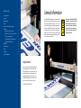
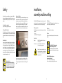
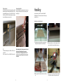
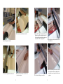
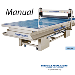
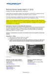
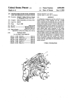
Manual
English
let signs be made easy
1
General information
Table of contents
Fingers or hand entanglement.
Clamp risk when pressurising the roller.
General information 3
Summary 4
Warning symbols 5
Safety 6
Installation, assembly and dismantling 7
Handling 9
Application on detached materials Application of colour on smooth sign surfaces
13
How to mount application tape 17
How to apply graphics to flexible materials 20
Adjustment of the roller speed
23
24
Troubleshooting 24
Repairs
24
Spare parts 24
Technical specifications
25
Consult Technical Manual for proper service
procedures.
Carefully read Operator’s Manual before
handeling the machine. Observe Instructions
and saftey rules when operating.
The ROLLSROLLER® Flatbed Applicator is specially designed for
applying foil and all types of self-adhesive vinyl (e.g. computer
cut lettering and digitally printed designs) to a wide variety
of materials including sheet metal, plastic, glass, Kapa board
and banners. ROLLSROLLER® is designed for dry application of
foil and transfer film, and produces a result completely free of
bubbles and creases. The machine consists of a table (flatbed)
and a gliding beam with a pneumatically activated roller that
is moved manually over the flatbed.
9
Maintenance No-text saftey sign “ read operators manual”
Before first use of the ROLLSROLLER® Flatbed Applicator, you should carefully read
this manual, which contains important
instructions, indications and safety information. Failure to read the manual may
result in serious injury to operators and
damage to the machine.
Electrical
Shock/electrocution
Congratulations!
You have just invested in a flat applicator that will make
your work significantly more efficient. The ROLLSROLLER® Flatbed Applicator is easy to operate. However, you
should still take the time to read through this manual
carefully. This will help you to get the best out of your
ROLLSROLLER® Flatbed Applicator and minimise risk of
injury to the operator and damage to the machine.
Good luck with your ROLLSROLLER®.
2
3
Enligt ISO 11684:1995
Move roller up and down.
Feet or toe entanglement.
Clamp risk when using height adjustment.
Adjust working height.
Summary
To use your ROLLSROLLER® safely, you need to be familiar
with the warning symbols in this manual.
Enligt ISO 11684:1995
No-text saftey sign “ read operators manual”
Consult Technical Manual for proper service
procedures.
Fingers or hand entanglement.
Clamp risk when pressurising the roller.
No-text saftey sign “ read operators manual”
Carefully read Operator’s Manual before
handeling the machine. Observe Instructions
and saftey rules when operating.
Move roller up and down.
Electrical
Shock/electrocution
Electrical
Shock/electrocuti
Emergency
stop function
Reset button
Risk of crushing between roller
and glass panel.
Electrical risks.
Media holder
Fingers or hand entanglement.
Clamp risk when pressurising the roller.
Adjust working height.
Feet or toe entanglement.
Clamp risk when using height adjustment.
No-text saftey sign “ read operators manual”
Consult Technical Manual for proper service
procedures.
Carefully read Operator’s Manual before
handeling the machine. Observe Instructions
and saftey rules when operating.
Electrical
Shock/electrocution
Cutting mat
Art no: 10175
Flatbed
Feet or toe entanglement.
Clamp risk when using height adjustment.
Move roller up and down.
Feet or toe entanglement.
Clamp risk when using height adjustment.
Adjust
working height.
Move roller up and
down.
Adjust working height.
Electrical
Shock/electrocution
Risk of crushing between
floor and legs.
Art no: 10176
Power switch
Read the manual.
Fingers or hand entanglement.
Clamp risk when pressurising the roller.
No-text saftey sign “ read operators manual”
Consult Technical Manual for proper service
procedures.
Carefully read Operator’s Manual before
handeling the machine. Observe Instructions
and saftey rules when operating.
Fingers or hand entanglement.
Clamp risk when pressurising the roller.
Move roller up and down.
No-text saftey
sign
read operators
manual”
Fingers
or“ hand
entanglement.
Clamp risk when pressurising the roller.
Carefully read Operator’s Manual before
handeling the machine. Observe Instructions
and saftey rules when operating.
Consult
Technical
Manual
foroperators
proper service
No-text
saftey sign
“ read
manual”
procedures.
Carefully read Operator’s Manual before
handeling the machine. Observe Instructions
and saftey rules when operating.
Consult Technical Manual for proper service
procedures.
Side pocket
Art no: 10178
Regulator
Adjustment
screws
Adjust working height.
EnligtEnligt
ISO 11684:1995
ISO 11684:1995
Control lever
Art no: 10174
Emergency
stop function
Glide beam
Roller
Consult Technical Manual for proper service
procedures.
Carefully read Operator’s Manual before
handeling the machine. Observe Instructions
and saftey rules when operating.
Feet or toe entanglement.
Clamp risk when using height adjustment.
Manometer
Adjust working height.
Warning symbols
Fingers or hand entanglement.
Clamp risk when pressurising the roller.
Control lever
Move roller up and down.
Feet or toe entanglement.
Clamp risk when using height adjustment.
Electrical
Shock/electrocution
Height-adjustable roller.
Art no: 10177
4
Art no: 10180
Electrical
Shock/electrocution
Contact a technician.
Art no: 10179
5
Enligt
ISO
11684:1995
Safety
Installation,
assembly and dismantling
Emergency situations
When the roller is pneumatically pressed against the flatbed,
there is a risk of crushing and catching. Take care when operating the ROLLSROLLER®, especially if more than one operator is
using it.
In the event of an emergency, use the available emergency stop
functions. When the emergency stop is activated, the pneumatic cylinders are depressurised and return to the idle position
Move roller up and down.
Feet or toe entanglement.
(this means that the roller moves
upwards). Before the equipClamp risk when using height adjustment.
ment can be used again after an emergency stop, you must
switch the control levers to the neutral position, turn the emergency stop knob anti-clockwise and press in the reset button.
Personal safety equipment
No personal safety equipment is required.
Testing of safety functions
The safety functions should be tested in connection with installation, servicing, maintenance etc. These include the emergency
stop function and the mechanical stop function for the glide
beam.
Fingers or hand entanglement.
Clamp risk when pressurising the roller.
No-text saftey sign “ read operators manual”
Carefully read Operator’s Manual before
handeling the machine. Observe Instructions
and saftey rules when operating.
Remaining risks
Consult technical manual
for proper service
procedures
Positioning
Delivery inspection
Before use
The following units are included when the machine is delivered:
• Manual
• Scissors
• ROLLSROLLER® Flatbed Applicator
Clean and lubricate the sliding bars.
The ROLLSROLLER® Flatbed Applicator should be placed on an
even, moisture-free, vibration-free surface.
After use
Place the roller in the idle position (raised 5 mm above the
flatbed).
Consult Technical Manual for proper service
procedures.
Connections
Voltage: Air connection: Electrical
Certain risks cannot be eliminated through technical safety measures alone. There is a risk of crushing and catching when the
roller is pneumatically pressed against the flatbed. A warning
symbol is displayed on or immediately beside the glide beam.
There is a risk of severe crushing and catching when the roller
is pneumatically pressed against the supporting bars. Never
pressurise the roller without first ensuring that the sign material
is positioned underneath the roller.
Read operators manual
The ROLLSROLLER® Flatbed Applicator should be assembled
and used at normal room temperature with normal humidity
levels. This minimises the occurrence of static electricity.
Adjust working height.
Read operators manual
Consult technical manual
for proper service
procedures
230 V AC 50 Hz, available in US version
110 V AC 60 Hz
max. 8 bar, filtered, moisture-free air.
3–4 bar used during operation.
ROLLSROLLER® Flatbed Applicator
with unmounted glide beam
Assembly may only be performed by the
supplier or staff authorised by the supplier.
Shock/electrocution
Electrical connectors may only be connected to sockets with the correct voltage. All
other operations may only be performed
by authorised staff.
ROLLSROLLER® Flatbed Applicator
with mounted glide beam
1. Remove the protective film/packaging.
2. Remove the strips holding the glide beam in place.
Fingers or hand
entanglement
Electrical
Shock/electrocution
A red emergency stop button is located at either end of the
glide beam. (ROLLSROLLER® models 280 and 340 have only
one emergency stop button located at the centre of the glide
beam.)
Unauthorised use
The machine may only be used for its
intended purpose as specified in this manual. All other use may result in damage
or injury, and is at the user’s own risk.
exempel sid 42
bild som visar om det finns
särskild risk för ström
behövs kanske inte ??
6
Fingers or hand
entanglement
7
exempel sid 42
Lifting instructions
Height-adjustable table
The ROLLSROLLER® should be lifted with a pallet lift or a forklift
fitted with long forks, with a minimum fork length of 1,700 mm
and minimum lifting capacity of 1,000 kg (2,200 mm for ROLLSROLLER® models 540/220). The forks must be positioned within
the specified lifting area (see picture below).
If your ROLLSROLLER® is height-adjustable, use the buttons on
the long side of the table to achieve the optimum ergonomic
working height.
Handling
No specific training is required to use the ROLLSROLLER®
Flatbed Applicator. This user manual contains all the necessary
instructions for use.
Application on detached materials
1. For application on thick materials, for instance bent metal Oil
2. Place the metal sheet on a section of polystyrene or similar sheets, position the material in the centre of the table.
material to stabilise the sign and distribute the pressure.
After adjusting the table’s height, you must wait 60 seconds
before using the height adjustment function again.
If a problem occurs, the height adjustment function can
be reset by pressing and holding the “down” button until a
click is heard.
To lubricate the sliding bars, use oil WD 40 or CRC 5-56, or an
equivalent oil.
For the compressor P30/6, use oil SINCOM/32E or equivalent.
8
3. Place the graphic on the substrate and measure to the exact 4. Using the control lever on the top of the machine, press the size.
9
roller against the substrate to fix the graphic into place.
6. Peel off the liner from the half that is above the roller.
5. Fold half of the graphic over the roller.
9. Apply one half of the graphic to the substrate. When you get right to the edge, raise the roller slightly so that it does not roll onto the table. Always make sure that the graphic is pres-
sed against the roller before starting application.
10. Place the glide beam at the point where the liner was cut. Pressurise the roller.
12. Take hold of the liner that you folded in from the other side.
7. Cut the liner, leaving a surplus border of about 10 cm.
8. Fold the liner back underneath the roller to form an even 10
pleat, as shown in picture.
Move the glide beam over the surface. Always make sure
that the graphic is pressed against the roller before starting application.
11. Fold the other half of the graphic over the roller.
11
Application of graphic film on flat sign surfaces
13. Apply the remaining part of the design to the substrate using the roller. Always remember to raise the roller slightly when it gets to the edge.
14.
1. Place the sign material at the centre of the table and pull 2. Cut the graphic film to the appropriate length.
the graphic film over the substrate.
16. The result: a smooth sign without creases or bubbles.
15. Trim to size if the graphic is larger than the substrate.
3. Press the roller against the substrate to fix the graphic film 12
into place.
4. Fold half of the graphic film over the roller.
13
5. Peel off the liner from the graphic film at a 45 degree angle.
6. Cut the liner, leaving a surplus border of about 10 cm.
7. Fold the liner back underneath the roller ...
8. ... so that it forms an even pleat.
9. Apply one half of the graphic film using the roller. Always 10. Press the roller down at the point where you cut, and fold the other half of the foil over the roller.
make sure that the graphic is pressed against the roller before starting application.
11. Take hold of the part of the liner that you folded under-
12. ... and peel off the liner.
neath the roller ...
14
15
How to mount application tape
2. Pull out a length of application tape and fold it over the roller.
13. Apply the other half of the graphic film using the roller. 14. Trim.
Always make sure that the graphic is pressed against the roller before starting application.
1. Place a roll of application tape in the media holder. Choose whether or not you want to use a core holder.
15. You have now finished applying the graphic film.
4.... and align it with the edge of the roll to ensure even appli-
3. Take hold of the application tape underneath the roller ...
16
17
cation
10. Push the glide beam back, press the roller down and apply
the last piece of tape in the opposite direction.
5. Press the roller down while keeping hold of the roll.
6. Move the roller forwards about 10 cm.
9. Trim before applying the last piece of tape. If you are apply
ing tape to several graphics simultaneously, raise the roller
and repeat the first steps in the same way as for the first
graphics.
8. Raise the roller and pull it forwards slightly until the roller is 7. Place the graphic film beside the application tape.
18
positioned above the graphic. Make sure that the graphic is lying flat when you press the roller down. Now apply the tape over the graphic. Stop about 10 cm before reaching the end of the graphic.
11. Trim.
19
How to apply graphics to flexible materials
2. Place the graphic on the substrate and measure to the exact
1. Flatten the substrate using the roller.
5. Peel off the liner.
6. Cut the liner, leaving a surplus border of about 10 cm.
size.
8. Apply half of the graphic using the roller. Press the roller 3. Press the roller down to fix the graphic into place.
4. Fold half of the graphic over the roller.
20
7. Fold the liner underneath the roller. Make sure it forms an even pleat.
21
down against the substrate.
Feet or toe entanglement.
Clamp risk when using height adjustment.
Move roller up and down.
Adjust working height.
Adjustment of the roller speed
Fingers or hand entanglement.
Clamp risk when pressurising the roller.
No-text saftey sign “ read operators manual”
If you want the roller to move faster or slower, you can adjust
the speed. Please note that this is normally not necessary, since
the
speed
is preset at the factory.
Consultroller
Technical Manual
for proper service
procedures.
Carefully read Operator’s Manual before
handeling the machine. Observe Instructions
and saftey rules when operating.
Electrical
Shock/electrocution
Contact a technician.
10. Take hold of the piece of liner you folded underneath the roller.
9. Fold the other half over the roller.
12. Remove the application tape, using the roller to hold the material in place.
11. Apply the other half of the graphic using the pressurised roller.
22
1.Use the two adjustment screws on either side of the glide
beam. Unfasten the grooved lock nut. The lower screw reduces the speed and the upper screw increases the speed.
Adjust the screws to the desired speed on one side. Change sides and adjust on the other side so that the roller can be
lowered flat against the table. Lock with the lock nut.
23
Maintenance
Technical specifications
Every day
The machine pulls unevenly during application
• Make sure that the roller is not damaged and has nothing stuck to it.
• Check the emergency stop function and controls.
Contact a technician.
Enligt ISO 11684:1995
ROLLSROLLER®
280/145 MDF
ROLLSROLLER® 280/145
ROLLSROLLER® 340/145
Overall length
2 800 mm
2 800 mm
3 400 mm
Overall width
1 710 mm
1 710 mm
1 710 mm
The table’s height adjustment function doesn’t work
Bed width
1 450 mm
1 450 mm
1 450 mm
If there are problems with the height adjustment function,
you can reset the function by pressing and holding the “down”
button until a click is heard.
If this doesn’t help, contact a technician.
Overall height
1 520 mm
1 520 mm
1 520 mm
Length of working area
2 500 mm
2 500 mm
3 100 mm
Width of working area/roller width
1 400 mm
1 400 mm
1 400 mm
60 mm
60 mm
60 mm
• Lubricate the sliding bar’s slide surfaces.
• If your ROLLSROLLER has a compressor, see enclosed ma-
nual for maintenance instructions.
Repairs
Working height, standard model
920 mm
920 mm
920 mm
170 kg
270 kg
320 kg
MDF
glass
glass
As necessary
Contact a technician.
Cutting mat, 4 mm
yes
yes
yes
Side pockets
no
no
no
Illumination
not illuminated
6x36W fluorescent
9x36W fluorescent
-
230 volt/50 Hz **
230 volt/50 Hz **
Once a week
• Wipe any dust off the glide beam’s sliding bar.
Once a month
Feet or toe entanglement.
Clamp risk when using height adjustment.
•
•
Check the bearing play in the glide beam (contact a technician).
Dust the cutting mat with talcum powder.
(The cutting mat is dusted with talcum powder at the fac-
tory, but should be dusted again when it is turned, to prevent vinyl or other materials from fastening on the mat. Spread talcum powder on the mat and distribute it with a window scraper. Vacuum or sweep off any surplus talcum powder and wipe the mat with a dry cloth.)
Move roller up and down.
Weight
Adjust working height.
You should first try contacting a technician through the
dealer where you bought your ROLLSROLLER®.
If this is not possible, contact
ROLLSROLLER® Technical Service,
phone +46 54 770 70 70.
Fingers or hand entanglement.
Clamp risk when pressurising the roller.
No-text saftey sign “ read operators manual”
Max. thickness of sign substrate (standard)*
Consult Technical Manual for proper service
procedures.
Carefully read Operator’s Manual before
handeling the machine. Observe Instructions
and saftey rules when operating.
Bed surface
Voltage
Air pressure
6–8 bar required
6–8 bar required
6–8 bar required
Media holder for end of bed
optional
optional
optional
Height-adjustable, 750–1,100 mm
optional
optional
optional
-
-
-
optional
optional
optional
Additional glide beam with roller
Low-noise compressor, 45 db
The equipment may only be used for its
intended purpose as specified in this manual. All other use may result in damage
or injury, and is at the user’s own risk.
Electrical
Shock/electrocution
Troubleshooting
* The roller height is adjusted pneumatically (max. 60 mm) and moved manually
across the working area. The operator can stand on either side of the table. Rollers
that can be adjusted to handle materials thicker than 60 mm (max. 100 mm) can
be supplied on request (does not apply to ROLLSROLLER® 280 and 340).
** Available in US version with 110 V AC 60 Hz.
The rubber roller won’t move up and down
Reset the emergency stop function
Reset the controls
Activate the reset button
Check the air connections
If none of this helps, contact a technician.
Spare parts
You can download a list of spare parts at www.rollsroller.se.
Alternatively, contact the dealer where you bought your ROLLSROLLER.
24
25
Technical specifications
Technical specifications
ROLLSROLLER® 400/150
Overall length
4 000 mm
ROLLSROLLER® 400/170
4 000 mm
ROLLSROLLER® 540/170
5 400 mm
ROLLSROLLER® 540/220
Overall length
5 400 mm
ROLLSROLLER® 605/170
6 050 mm
ROLLSROLLER® 1080/170
10 080 mm
Overall width
1 760 mm
1 960 mm
1 960 mm
Overall width
2 460 mm
1 960 mm
1 960 mm
Bed width
1 500 mm
1 700 mm
1 700 mm
Bed width
2 200 mm
1 700 mm
1 700 mm
Overall height
1 520 mm
1 520 mm
1 520 mm
Overall height
1 520 mm
1 520 mm
1 520 mm
Length of working area
3 600 mm
3 600 mm
5 000 mm
Length of working area
5 000 mm
5 650 mm
10 400 mm
Width of working area/roller width
1 400 mm
1 630 mm
1 630 mm
Width of working area/roller width
2 050 mm
1 630 mm
1 630 mm
60 mm
60 mm
60 mm
60 mm
60 mm
60 mm
920 mm
920 mm
920 mm
920 mm
920 mm
920 mm
650 kg
725 kg
800 kg
950 kg
850 kg
1 630 kg
glass
glass
glass
glass
glass
glass
Max. thickness of sign substrate (standard)*
Working height, standard model
Weight
Bed surface
Max. thickness of sign substrate (standard)*
Working height, standard model
Weight
Bed surface
Cutting mat, 4 mm
yes
yes
yes
Cutting mat, 4 mm
yes
yes
yes
Side pockets
yes
yes
yes
Side pockets
yes
yes
yes
Illumination
Illumination
20x36W fluorescent tubes
16x36W fluorescent tubes
+ 4x18W fluorescent tubes
32x36W fluorescent tubes
Voltage
230 volt/50 Hz **
230 volt/50 Hz **
230 volt/50 Hz **
Air pressure
6–8 bar required
6–8 bar required
6–8 bar required
yes
yes
yes
optional
optional
optional
9x36W fluorescent tubes
12x36W fluorescent tubes
16x36W fluorescent tubes
Voltage
230 volt/50 Hz **
230 volt/50 Hz **
230 volt/50 Hz **
Air pressure
6–8 bar required
6–8 bar required
6–8 bar required
yes
yes
yes
Height-adjustable, 750–1,100 mm
optional
optional
optional
Additional glide beam with roller
optional
optional
optional
Low-noise compressor, 45 db
optional
optional
optional
Media holder for end of bed
* The roller height is adjusted pneumatically (max. 60 mm) and moved manually
across the working area. The operator can stand on either side of the table. Rollers
that can be adjusted to handle materials thicker than 60 mm (max. 100 mm) can
be supplied on request (does not apply to ROLLSROLLER® 280 and 340).
Media holder for end of bed
Height-adjustable, 750–1,100 mm
Additional glide beam with roller
optional
optional
optional
Low-noise compressor, 45 db
optional
optional
optional
* The roller height is adjusted pneumatically (max. 60 mm) and moved manually
across the working area. The operator can stand on either side of the table. Rollers
that can be adjusted to handle materials thicker than 60 mm (max. 100 mm) can
be supplied on request (does not apply to ROLLSROLLER® 280 and 340).
** Available in US version with 110 V AC 60 Hz.
** Available in US version with 110 V AC 60 Hz.
26
27
Patent registration numbers: SE 9702032-5, AU 730769, CA 2, 289, 469, CH 0986459, CN ZL 98805672.0, DE 69826655.0-08, EU, F, I, GB 0 986 459,
E ES2230695T3, GR 20040404376, II 132849, MX 209756, N 315014, RU 2220050, TR 199902925B, USA 6, 102, 096, 6, 406, 582
www.rollsroller.se
Januari 2009
ROLLSROLLER® is manufactured by Reklamidé
Frögatan 3, 653 43 Karlstad, Sweden • Tel. +46 54 770 70 00 • E-mail: [email protected]