1
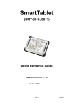
M AESTRO H ERITAGE 3G S ERIES
Q UICK S TART G UIDE & U SER M ANUAL R EV. 0.1
WWW. MAESTRO - WIRELESS . COM
E MAIL : CONTACT @ MAESTRO - WIRELESS . COM
T EL : 852 2869 0688
FAX : 852 2525 4701
A DDRESS : R OOM 3603-3609, 36/F, 118 C ONNAUGHT R OAD W EST, S HEUNG WAN , H ONG KONG
Revision history
Rev.
0.1
Date
8 April 2011
Details
First release
Originated by
Samuel Chereau
This manual is written without any warranty.
Maestro Wireless Solutions Ltd. reserves the right to modify or improve the product and its accessories
which can also be withdrawn without prior notice.
Besides, our company stresses the fact that the performance of the product as well as accessories depends
not only on the proper conditions of use, but also on the environment around the places of use.
Maestro Wireless Solutions Ltd. assumes no liability for damage incurred directly or indirectly from
errors, omissions or discrepancies between the modem and the manual.
This software, solution or application is provided on an "as is" basis. No warranty whether expressed or
implied is given by Maestro Wireless Solutions Ltd. in relation to this software, solution or application.
User shall assume the entire risk of using or relying on this software, solution, application.
In no event will Maestro Wireless Solutions Ltd. be liable for any loss or damage including without
limitation, indirect or consequential loss, damage, or any loss, damage whatsoever arising from loss of
data or profit arising out of, or in connection with, the use of this software, application or solution. Every
effort is made to keep the software, application or solution up and running smoothly. However, Maestro
Wireless Solutions Ltd. takes no responsibility for, and will not be liable for, the software, application or
solution being temporarily unavailable due to technical issues beyond our control.
The above terms and conditions are subject to change without prior notice. The present use of this software, application or solution implies the user approves and understands all the above terms and conditions.
Confidential, the whole document is the sole property of Maestro Wireless Solutions ltd.
3603-9, 36/F., 118 Connaught Road West, Sheung Wan, Hong Kong
[email protected]
1
Contents
1 Introduction
5
1.1 Package . . . . . . . . . . . . . . . . . . . . . . . . . . . . . . . . . . . . . . . . . . . . . . . .
5
1.2 Interfaces . . . . . . . . . . . . . . . . . . . . . . . . . . . . . . . . . . . . . . . . . . . . . . .
5
1.2.1 Status indicator . . . . . . . . . . . . . . . . . . . . . . . . . . . . . . . . . . . . . . . .
6
1.2.2 SMA female antenna connector (Main)
. . . . . . . . . . . . . . . . . . . . . . . . . .
6
1.2.3 SMA female antenna connector (Aux) . . . . . . . . . . . . . . . . . . . . . . . . . . .
7
1.2.4 Serial port: 9 pins D-Sub Female connector (RS232) . . . . . . . . . . . . . . . . . . .
7
1.2.5 Power input: 4 pins connector . . . . . . . . . . . . . . . . . . . . . . . . . . . . . . . .
7
1.2.6 Slide switch . . . . . . . . . . . . . . . . . . . . . . . . . . . . . . . . . . . . . . . . . .
8
1.3 Optional accessories . . . . . . . . . . . . . . . . . . . . . . . . . . . . . . . . . . . . . . . . .
8
2 Installation
10
2.1 Install the SIM card . . . . . . . . . . . . . . . . . . . . . . . . . . . . . . . . . . . . . . . . . . 10
2.2 Connect the external antenna (SMA type) . . . . . . . . . . . . . . . . . . . . . . . . . . . . . 10
2.3 Connect the modem to external device . . . . . . . . . . . . . . . . . . . . . . . . . . . . . . . 10
2.4 Connect the DC power supply . . . . . . . . . . . . . . . . . . . . . . . . . . . . . . . . . . . . 11
3 Configuration
12
3.1 Download the SofTool configuration software . . . . . . . . . . . . . . . . . . . . . . . . . . . 12
3.2 Use of the SofTool configuration software . . . . . . . . . . . . . . . . . . . . . . . . . . . . . 12
3.2.1 COM port . . . . . . . . . . . . . . . . . . . . . . . . . . . . . . . . . . . . . . . . . . . 12
3.2.2 Modem status . . . . . . . . . . . . . . . . . . . . . . . . . . . . . . . . . . . . . . . . 12
3.2.3 Network and Serial port . . . . . . . . . . . . . . . . . . . . . . . . . . . . . . . . . . . 13
3.2.4 Add-on board . . . . . . . . . . . . . . . . . . . . . . . . . . . . . . . . . . . . . . . . . 13
3.2.5 GPRS & TCP/IP connection . . . . . . . . . . . . . . . . . . . . . . . . . . . . . . . . . 14
3.2.6 Call screening . . . . . . . . . . . . . . . . . . . . . . . . . . . . . . . . . . . . . . . . 14
3.2.7 Dynamic DNS . . . . . . . . . . . . . . . . . . . . . . . . . . . . . . . . . . . . . . . . 14
3.2.8 Remote Configuration . . . . . . . . . . . . . . . . . . . . . . . . . . . . . . . . . . . . 15
3.2.9 IP ping . . . . . . . . . . . . . . . . . . . . . . . . . . . . . . . . . . . . . . . . . . . . . 15
3.2.10 Command String . . . . . . . . . . . . . . . . . . . . . . . . . . . . . . . . . . . . . . . 16
Confidential, the whole document is the sole property of Maestro Wireless Solutions ltd.
3603-9, 36/F., 118 Connaught Road West, Sheung Wan, Hong Kong
[email protected]
2
3.2.11 TMODE . . . . . . . . . . . . . . . . . . . . . . . . . . . . . . . . . . . . . . . . . . . . 16
3.2.12 DOTA . . . . . . . . . . . . . . . . . . . . . . . . . . . . . . . . . . . . . . . . . . . . . 16
3.2.13 Send SMS . . . . . . . . . . . . . . . . . . . . . . . . . . . . . . . . . . . . . . . . . . 17
3.3 Debug, or further command using Smart Terminal as example
. . . . . . . . . . . . . . . . . 17
3.4 Basic operation . . . . . . . . . . . . . . . . . . . . . . . . . . . . . . . . . . . . . . . . . . . . 18
4 Specifications
19
5 Related Information
21
5.1 Related documents . . . . . . . . . . . . . . . . . . . . . . . . . . . . . . . . . . . . . . . . . . 21
5.2 Related software . . . . . . . . . . . . . . . . . . . . . . . . . . . . . . . . . . . . . . . . . . . 21
5.3 Factory settings . . . . . . . . . . . . . . . . . . . . . . . . . . . . . . . . . . . . . . . . . . . . 21
6 Troubleshooting
22
6.1 The modem’s LED does not light . . . . . . . . . . . . . . . . . . . . . . . . . . . . . . . . . . 22
6.2 The modem’s LED lights but does not blink long time after power up . . . . . . . . . . . . . . 22
6.3 The modem does not respond to the terminal program
. . . . . . . . . . . . . . . . . . . . . 22
Confidential, the whole document is the sole property of Maestro Wireless Solutions ltd.
3603-9, 36/F., 118 Connaught Road West, Sheung Wan, Hong Kong
[email protected]
3
Safety precautions
General precautions
– The modem generates radio frequency (RF) power. When using the modem care must be taken on
safety issues related to RF interference as well as regulations of RF equipment.
– Do not use your phone in aircraft, hospitals, petrol stations or in places where using GSM products is
prohibited.
– Be sure that the modem will not be interfering with nearby equipment. For example: pacemakers or
medical equipment. The antenna of the modem should be away from computers, office equipment,
home appliance, etc.
– An external antenna must be connected to the modem for proper operation. Only used approved
antennas with the modem. Please contact authorized dealer on finding an approved antenna.
– Always keep the antenna with minimum safety distance of 26.6 cm or more from human body. Do not
put the antenna inside metallic box, containers, etc.
Using the modem in vehicle
– Check for any regulation or law authorizing the use of GSM in vehicle in your country before installing
the modem
– Install the modem by qualified personnel. Consult your vehicle dealer for any possible interference of
electronic parts by the modem.
– The modem should be connected to the vehicle’s supply system by using a fuse-protected terminal
in the vehicle’s fuse box
– Be careful when the modem is powered by the vehicle’s main battery. The battery may be drained
after extended period.
Protecting your modem
To ensure error-free usage, please install and operate your modem with care. Do remember the following:
– Do not expose the modem to extreme conditions such as high humidity/rain, high temperatures, direct
sunlight, caustic/harsh chemicals, dust, or water.
– Do not try to disassemble or modify the modem. There is no user serviceable part inside and the
warranty would be void.
– Do not drop, hit or shake the modem. Do not use the modem under extreme vibrating condition.
– Do not pull the antenna or power supply cable. Please attach or detach by holding the connector.
– Connect the modem only according to the instruction manual. Failure to do it will void the warranty.
Confidential, the whole document is the sole property of Maestro Wireless Solutions ltd.
3603-9, 36/F., 118 Connaught Road West, Sheung Wan, Hong Kong
[email protected]
4
Chapter 1
Introduction
Maestro Heritage 3G is a ready-to-use 3G/GSM1 modem for data and SMS services. It also supports 3G
HSPA (Down link: Cat 8, 7.2Mbps; Up link: Cat 5, 2Mbps) GPRS (Class 12) and EDGE (Class 12) for high
speed data transfer. Maestro Heritage 3G can be easily controlled by using AT command for all kinds of
operations. With standard 9 pins RS232 port, the Maestro Heritage 3G can be set up with minimal effort.
Maestro Heritage 3G is also having an Expansion Slot to make the modem becomes even more powerful.
You can plug into it some Maestro Heritage Add-on unit such as Input/Output, Ethernet Router, GPS,
Analog/Pulse, etc. . .
1.1
Package
The Maestro Heritage 3G package should include the following:
– Maestro Heritage 3G modem x1
– Power cord with fuse x1
– Safety note x1
– DIN rail with screws x1
1.2
Interfaces
1
– Tri-band UMTS/HSPA (I, II, V) connectivity
– Quad-band GSM, GPRS and EDGE (850, 900, 1800, 1900MHz) connectivity
Confidential, the whole document is the sole property of Maestro Wireless Solutions ltd.
3603-9, 36/F., 118 Connaught Road West, Sheung Wan, Hong Kong
[email protected]
5
1.2.1
Status indicator
The LED will indicate different status of the modem:
– GSM status:
• off: modem is switched off
• on: modem is connecting to the network
• flashing slowly: modem is in idle mode
• flashing rapidly: modem is in transmission/communication (GSM only)
– 3G: availability of 3G network
– Rx: data received over TCP/UDP
– Tx: data transmitted over TCP/UDP
– Signal strength:
• strong: CSQ 27 or higher
• medium: CSQ 23 – 26
• low: CSQ 14 – 22
• weak: CSQ 1 – 13
1.2.2
SMA female antenna connector (Main)
Connect it to an external antenna with SMA male connector. Make sure the antenna is tuned for the
frequency band(s) used (one or more of 850/900/1800/1900/2100MHz) with impedance of 50Ohm, and
also connector is secured tightly.
Confidential, the whole document is the sole property of Maestro Wireless Solutions ltd.
3603-9, 36/F., 118 Connaught Road West, Sheung Wan, Hong Kong
[email protected]
6
1.2.3
SMA female antenna connector (Aux)
The purpose of the second connector is an optional diversity antenna when 3G network is used. Connect
it to an external antenna with SMA male connector. Make sure the antenna is tuned for the frequency
band(s) used (one or more of 850/1900/2100MHz) and with impedance of 50Ohm, and also connector is
secured tightly.
1.2.4
Serial port: 9 pins D-Sub Female connector (RS232)
The connector provides serial link to the modem:
a Refer
1.2.5
Pin Number
Name
EIA designation
Type
1
2
3
4
5
6
7
8
9
DCD
RXD
TXD
DTR
GND
DSR
RTS
CTS
RI
Data Carrier Detect
Receive Data
Transmit Data
Data Terminal Ready
Ground
Data Set Ready
Request To Send
Clear To Send
Ring Indicator or 6Va
Output
Output
Input
Input
Ground
Output
Input
Output
Output
to section1.2.6 for more details
Power input: 4 pins connector
Pin assignment:
Confidential, the whole document is the sole property of Maestro Wireless Solutions ltd.
3603-9, 36/F., 118 Connaught Road West, Sheung Wan, Hong Kong
[email protected]
7
Pin number
Name
Functions
1
2
3
4
Not used
Not used
POWER POWER +
None
None
DC power negative input
DC power positive input
A cable, included in the package shall be used for power supply connection:
1.2.6
Slide switch
The Heritage 3G version adds a new hardware feature selectable through the slide switch. That will give
you the ability to power an external equipment without the need of another power supply (e.g. RS485
converter, Bluetooth adapter, sensors, etc...). For that purpose you have two choices of enabling the 6V
output: on the serial port or on the add-on board connector; see below for more details on the switch
selection.
Note: 6VDC output maximum current is 900mA.
1. 6V output is enabled on the add-on board connector on pin 92
2. 6V output is disabled DB9 pin 9 is in normal state (i.e. ring notification; RI)
3. 6V output is enabled on the serial port DB9 pin 9 (i.e. ring notification; RI)
1.3
Optional accessories
You may contact your sales agent for the following optional accessories.
2 Pin
#9: is the #5 top left pin on the add-on board connector
Confidential, the whole document is the sole property of Maestro Wireless Solutions ltd.
3603-9, 36/F., 118 Connaught Road West, Sheung Wan, Hong Kong
[email protected]
8
External antenna
– Magnetic mount type
– Frequency GSM 900/1800 band (3dBi) - Ref: ACC-A01
– Frequency GSM 850/1900 band (0dBi) - Ref: ACC-A05
– VSWR < 1.5:1
– Height ~ 236 mm (including magnetic base)
– Cable: Type RG-174U length 2.5m
– SMA male connector on cable end
– Color: back (SMA connector silver)
RS232 cable - Ref: ACC-CA07
– Direct connection with standard 9-pin RS-232 port (DTE)
– Shielded cable
– Cable length 1m (w/ connector)
Confidential, the whole document is the sole property of Maestro Wireless Solutions ltd.
3603-9, 36/F., 118 Connaught Road West, Sheung Wan, Hong Kong
[email protected]
9
Chapter 2
Installation
2.1
Install the SIM card
Use a ball pen or paper clip to press the SIM card holder eject button. The SIM card holder will come out
a little, take it out and put the SIM card in the tray. Make sure the SIM card is fully inserted inside the tray,
and put it back into the slot.
Note: DO NOT pull out the SIM holder without pushing the ejector.
2.2
Connect the external antenna (SMA type)
Connect this to an external antenna with SMA male connector and secure it tightly. Make sure the antenna
is tuned for the frequency band(s) used (one or more of 850/900/1800/1900/2100Mhz) and with impedance
of 50Ohm.
Note: Incorrect antenna will affect communication and even damage the modem.
Diversity antenna for "AUX" is optional when used with 3G network.
2.3
Connect the modem to external device
You can use the RS232 cable to connect the modem’s Sub-D connector to external controller/computer.
Connection example using RS232 cable:
Confidential, the whole document is the sole property of Maestro Wireless Solutions ltd.
3603-9, 36/F., 118 Connaught Road West, Sheung Wan, Hong Kong
[email protected]
10
Note: The Heritage modem is a DCE, meaning that Tx pin is an input, and Rx pin is an output.
If your serial equipment is also a DCE, you have to use an RS-232 crossed cable (also known
as “null modem cable”) to connect it to the modem. If your serial equipment is a DTE, you need
to use a straight cable. An easy way to identify your equipment is to remember that a PC is a
DTE. If you use a straight cable to connect the PC to the serial equipment, then you will use a
crossed cable to connect the modem to the serial equipment, and vice-versa.
2.4
Connect the DC power supply
Connect the open ending of the inducted power cord to a DC supply. Refer to the following for power supply
requirement.
Input voltage range
Rated current
7V – 32V
900 mA
Connect the connector to the modem. The modem will turn on automatically.
The status indicator on the modem will be lit when power on. After a few seconds it will go flashing slowly
(registered to the network successfully refer to 1.2.1 on page 6).
Confidential, the whole document is the sole property of Maestro Wireless Solutions ltd.
3603-9, 36/F., 118 Connaught Road West, Sheung Wan, Hong Kong
[email protected]
11
Chapter 3
Configuration
3.1
Download the SofTool configuration software
First find the SofTool configuration software at this address: http://software.maestro-wireless.com/.
Proceed and follow the instructions on screen.
Note: Your computer needs Windows XP or further, up to date, and with .NET 4.0 client installed1 .
Then open the software, you can find the shortcut on your desktop, or access it by the Start menu > All
Programs > Maestro Wireless Solutions > HER010 Heritage SofTool Configuration Software.
3.2
3.2.1
Use of the SofTool configuration software
COM port
Once open you will have to select the good serial port configuration, it is always set on the default value
when launch. (By default: COM1, 115200, 8 data 1 stop, none, with hardware flow control)
3.2.2
Modem status
1 http://www.microsoft.com/downloads/en/details.aspx?FamilyID=9cfb2d51-5ff4-4491-b0e5-b386f32c0992&displaylang=en
Confidential, the whole document is the sole property of Maestro Wireless Solutions ltd.
3603-9, 36/F., 118 Connaught Road West, Sheung Wan, Hong Kong
[email protected]
12
After connection check you will first arrive on this Modem Status tab. It displays the reception signal strength
(refreshed every 5sec.), your SIM card network name. And all the versions of the embedded application.
Useful to send a screen shot of this tab to your distributor, or Maestro contact, when you encounter any
problem with your modems.
3.2.3
Network and Serial port
In this second tab you can change all the settings of the serial port, and GSM band.
Note: Be aware that changing your serial port settings will need reloading of the application
with the selected settings after the modem reboot.
3.2.4
Add-on board
Confidential, the whole document is the sole property of Maestro Wireless Solutions ltd.
3603-9, 36/F., 118 Connaught Road West, Sheung Wan, Hong Kong
[email protected]
13
This tab allow you to switch to your add-on board, and set up the main feature of it. You also have a quick
look at all the inputs/outputs status and can use the auto-refresh function that will refresh the tab value
every 5 seconds. Allow you to test quickly your setup and check your connections.
3.2.5
GPRS & TCP/IP connection
In this tab you will be able to setup the most features of the SofTool. Most important is the APN. And
for example the Auto TCP connection, please refer to the ’Maestro Apps Note - Automatic connections rev0.3’ for more details. See Chapter 5 on page 21 for the Related Documents.
3.2.6
Call screening
This tab is reserved for the call screening settings, allow you to filter the incoming call to your modem up to
10 phone numbers.
3.2.7
Dynamic DNS
Confidential, the whole document is the sole property of Maestro Wireless Solutions ltd.
3603-9, 36/F., 118 Connaught Road West, Sheung Wan, Hong Kong
[email protected]
14
This tab allow you to setup your Dynamic DNS account. SofTool support the main Dynamic DNS provider
DynDNS and NoIP.
3.2.8
Remote Configuration
This tab allow you to setup the remote access settings for your modem. Enable to access it from outside,
and change AT command without the need to go on field. You can do that either via SMS or remote Telnet
connection.
3.2.9
IP ping
This tab allow you to ping a IP address on the internet, for test and debug purpose, it is then easy to check
your are well connected to your GPRS network.
Confidential, the whole document is the sole property of Maestro Wireless Solutions ltd.
3603-9, 36/F., 118 Connaught Road West, Sheung Wan, Hong Kong
[email protected]
15
3.2.10
Command String
This tab allow you to enter command string script easily in the modem. For more details refer to the Annex
of the SofTool software manual. See Chapter 5 on page 21 for the Related Documents.
3.2.11
TMODE
This tab is for the SofTool Tmode that allow to check your modem ROM, signal strength, IP address and
input voltage, and send alert by SMS if there is threshold on these values.
3.2.12
DOTA
This tab allow you to first setup your FTP server for DOTA upgrade, then combine with remote access, this
will allow you to update your modem firmware with only one SMS !
Confidential, the whole document is the sole property of Maestro Wireless Solutions ltd.
3603-9, 36/F., 118 Connaught Road West, Sheung Wan, Hong Kong
[email protected]
16
3.2.13
Send SMS
The tab allow you to send SMS easily using your Maestro Heritage modem.
3.3
Debug, or further command using Smart Terminal as example
First, you can find our Hyper Terminal substitute at the following address: http://software.maestro-wireless.
com/
Then follow the steps:
– Open the software, you can find the shortcut on your desktop, or access it by the Start menu > All
Programs > Maestro Wireless Solutions > Smart Terminal.
– Once open you will have to select the good serial port configuration (By default: COM1, 115200, 8
data 1 stop, none, with hardware flow control)
– Open the port by ticking the Port opened box :
– Then you can type command like “AT” and check the "OK" response from the modem. You can also
use any other AT commands.
Confidential, the whole document is the sole property of Maestro Wireless Solutions ltd.
3603-9, 36/F., 118 Connaught Road West, Sheung Wan, Hong Kong
[email protected]
17
3.4
Basic operation
Followings are examples of some AT commands. Please refer to the AT command document for a full
description.
Note: Issue AT+CMEE=1 to have extended error code (+CME ERROR)
Description
Network
registration
checking
Receiving signal
strength
Receiving an
incoming call
AT commands
Modem response
Comments
AT+CREG?
CREG=<mode>,1
CREG=<mode>,2
Modem registered to the network
Registration lost, re-registration attempt
Modem not registered on the network, no
registration attempt
First parameter has to be at least 15 for
normal communication
An incoming call is waiting
Answer the call
Communication established (Remember the
“;” at the end for “voice” call)
PIN code not entered (with +CME=1 mode)
AOC credit exceeded or a communication is
already established
Communication established (Remember the
“;” at the end for “voice” call)
CREG=<mode>,0
AT+CSQ
+CSQ:20,0
ATA
RING
OK
ATD1234567;
OK
Make a call
+CME ERROR: 11
+CME ERROR: 3
Make an
emergency call
Communication
loss
Hang up
ATD 112;
NO CARRIER
ATH
AT+CPIN=1234
OK
OK
+CME ERROR: 16
+CME ERROR: 3
PIN Code accepted
Incorrect PIN code (with +CME=1 mode)
PIN already entered (with +CME=1 mode)
AT&W
OK
Configuration settings are stored
Enter PIN code
Saves parameters
in non-volatile
memory
OK
Confidential, the whole document is the sole property of Maestro Wireless Solutions ltd.
3603-9, 36/F., 118 Connaught Road West, Sheung Wan, Hong Kong
[email protected]
18
Chapter 4
Specifications
– 3GPP FDD Release 6 HSUPA Compliant
– Tri-band UMTS/HxDPA (WCDMA/FDD) 2100/1900/850MHz (band I, II and IV)
– Downlink data rates up to HSDPA Category 8 (7.2 Mbps)
– Uplink data rates up to HSUPA Category 5 (2 Mbps)
– Quad-Band GSM 850/900/1800/1900MHz
– Support Data, Voice
– ETSI GSM Phase 2 + compliant
– LED Bar indication of RSSI, Network Registration, Up/Down data Traffic and 3G availability
– GPRS Class 12 / EDGE Class 12
– Real time clock backup by Super-Capacitor
– Built-in watchdog chip to prevent modem lock-up
– Control via AT command (GSM 07.05, GSM 07.07 and Sierra Wireless proprietary)
Power supply requirement:
– Input voltage range : 7-32V
– Rated current: 900mA
Typical current consumption:
GSM850/900MHz communication mode PCL=5
DCS1800/1900MHz communication mode PCL=0
GPRS850/900Mhz Transfer Mode class 12
GPRS1800/1900Mhz Transfer Mode class 12
UMTS Connected Mode BAND II @ +22 dBm
HSDPA Data Transfer2 Cat. 8 7.2Mbits/s BAND II
@ +22 dBm
Idle mode
@7V
200mA
250mA
450mA
380mA
500mA
@12V
170mA
150mA
260mA
200mA
320mA
@32V
60mA
50mA
90mA
80mA
120mA
600mA
380mA
140mA
100mA
38mA
18mA
Confidential, the whole document is the sole property of Maestro Wireless Solutions ltd.
3603-9, 36/F., 118 Connaught Road West, Sheung Wan, Hong Kong
[email protected]
19
Interfaces:
– SIM Holder
– 9 pin sub-D connector
– 4 pin power supply connector
– SMA antenna connector (Main and Aux) (50 Ohm)
– Din rail mountable
– Slide switch
– Expansion slot for add-on module for customized functions
Dimensions:
– Overall size: 79mm x 84mm x 27mm
– Weight: 100g
– Temperature range:
• Operating ETSI compliant: -20°C to +55°C
• Operating functional: -35°C to +75°C
• Storage: -40°C to +75°C
Confidential, the whole document is the sole property of Maestro Wireless Solutions ltd.
3603-9, 36/F., 118 Connaught Road West, Sheung Wan, Hong Kong
[email protected]
20
Chapter 5
Related Information
5.1
Related documents
– Sierra Wireless - AT Commands Interface Guide for Open AT Firmware
– Maestro Heritage - Software Tools - rev1.4
– Maestro Wireless Solutions - How to upgrade a modem in five easy steps
– Maestro Apps Note - Automatic connections - rev0.3
5.2
Related software
– SofTool configuration software
– SmarTerminal
5.3
Factory settings
The modem has the following factory settings. Please refer to the AT command document for the meaning
of each setting.
Related AT commands
Factory settings
Description
AT+WMBS
AT+IPR
AT+IFC
AT+ICF
ATE
AT&C
AT&D
ATQ
ATV
AT&S
ATS0
AT+CLIP
AT+CRLP
AT+CSCS
AT+CMGF
AT+CSMP
AT+CNMI
7
115200
2,2
3,4
1
1
2
0
1
1
0
0
Auto Quad Band Feature
DTE-DCE data rate
DTE-DCE flow control
DTE-DCE character framing
ECHO
DCD signal
DTR signal
Result code suppression
Response format
DSR signal
Auto answer
Calling line ID presentation
Calling line ID restriction
Character Set
Short message format
Test mode parameters
New message indication
“PCCP437”
1
1,67,0,0
0,1,0,0
Confidential, the whole document is the sole property of Maestro Wireless Solutions ltd.
3603-9, 36/F., 118 Connaught Road West, Sheung Wan, Hong Kong
[email protected]
21
Chapter 6
Troubleshooting
6.1
The modem’s LED does not light
– Check if the modem has been properly connected to a 7-32V power supply
– Check if the power connector is properly inserted
– Check the fuse on the power cord
6.2
The modem’s LED lights but does not blink long time after power
up
– Check if a valid SIM card has been properly inserted
– Check if the SIM card has been locked (refer to AT+CPIN command in AT command guide)
– Check if the external has been properly connected to the modem
– Check if the network coverage is available
6.3
The modem does not respond to the terminal program
– Check if the RS232 cable has been properly connected
– Check if your program has proper settings. Factory setting of the modem is:
• 115200 bps
• 8 data bits
• No parity bit
• 1 stop bit
Confidential, the whole document is the sole property of Maestro Wireless Solutions ltd.
3603-9, 36/F., 118 Connaught Road West, Sheung Wan, Hong Kong
[email protected]
22