1
R19 robot manual page 1
R19man.doc 2009-02-17
ATHENA
R19 ROBOT SYSTEM
User manual
R19 robot manual page 2
System Components:
A basic R19 robot system comprises the following: 1 R19 Robot arm
fitted with any options:
Electric or pneumatic gripper
Quickstop sensor
Tool changer
1 Track
1 Controller K11R
1 Teach box
1 Cable 9-way D-type each end (M-M) - K11R to teach box
1 Motor cable - K11R MS connector to robot 25-way D-type
1 Sensor and encoder cable - 25-way each end (M-F)
1 Cable, D-type 25-way male to 9-way female - K11R to PC RS232
1 Power cable to K11R
1 Pack of CONNECTORS:
1 output connector (unless already used for gripper)
1 input connector
1
stop circuit jack
1 Disk with software and manuals.
1 optional USB/serial adaptor
1 optional gripper pneumatics kit
1 optional Quickstop pneumatics kit
R19 robot manual page 3
1. INTRODUCTION
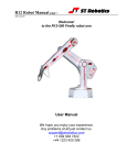
The R19, ATHENA is a robot arm of the cylindrical format i.e. its workspace is cylindrical.
It is highly suitable for bench top handling and is more accurate than other formats.
Athena has a nominal reach of 550mm. Athena is driven by stepping motors controlled by
intelligent micro-stepping MOS power drives with incremental encoder feedback. A choice
of grippers is available: pneumatic or electric. If fitted the pneumatic gripper is operated by
compressed air from 5 to 7 bar. This may be supplied by a compressor supplied with the
kit, or from another air supply.
The R19 robot system comprises 3 main units:- the robot, the controller, the computer or
terminal. The computer is used to program the controller. Once programmed the controller
will run the robot independently without the need for the terminal or computer but it is a
good idea to have a low cost terminal connected while the robot is in use.
OVERVIEW
All movement of the robot is controlled by the controller. As the controller may be both
reading sensors and signals from and controlling associated equipment it follows that all
decisions about robot activity are usually made by the controller which is capable of
running without any host computer. The function of the computer is to (a) program the
controller, (b) to copy (back up) the contents of controller RAM to disk and optionally (c) to
perform a supervisory role sending commands to the controller through the RS232
interface. The function of a terminal is to display information or questions and for the
operator to enter answers or commands (e.g. part type selection).
To program the controller with a computer you need to run the utility ROBWIN.EXE.
When ROBWIN is executed it immediately opens a communications window. Once
communication is established all your commands go to the controller not to the computer
you are typing on. Programming the controller involves programming the robot and the
interaction with other equipment. The robot and interfacing are programmed using
ROBOFORTH II and FORTH. There are two HTML manuals, ROBOFORTH covering
robot programming and the system manual, which describes the controller and interfacing.
You can use the dynamic links to see connected concepts. There is also a glossary on
disk, which gives a brief description of every command. Some commands are used only
by ROBWIN or are not very useful and these are in the glossary but not in the
ROBOFORTH manual. In particular you should start off with the “getting started” manual
which is a pdf.
All FORTH and ROBOFORTH commands are in UPPER CASE (press caps lock). You
can add commands written in lower case but these would be different
commands from those spelled in upper case.
R19 robot manual page 4
2. IMPORTANT DOS AND DON'TS
(1) DON'T ever disconnect or connect the robot while the controller is switched on. This
will result in damage to the electronics and the connectors themselves. Warranty claims
will not be accepted for damage resulting from this.
(2) DO be very careful not to "crash" i.e. drive any joint against a solid object so that it
stalls. Depending on the speed damage may result. At lower speeds the motors generate
higher torques so can do more damage. DON'T drive the waist against the stop.
(3) For the above reason DON’T use CALIBRATE unless you are sure the robot will not
crash into something in the workspace.
(4) DON'T use CALIBRATE unless you are sure the robot is in the valid position for
calibration including taking into account any complex end effector fitted.
(5) DO have your hand poised over the emergency stop button whenever testing a
program. Remember that because of its geometry the arm may describe wide arcs from
far apart points, and may collide with objects within its reach.
(6) DO make a back-up of the computer disk supplied as soon as possible.
(7) DO take appropriate measures to assess the risks and protect personnel from injury
(see next section)
R19 robot manual page 5
SAFETY IS YOUR RESPONSIBILITY
Risks
Because stepping motors raise more torque at low speeds a substantial low speed force
can be brought to bear especially on fingers, which may become trapped under or
between axes. Robot end effectors typically have sharp edges or fingers made of thin
metal, which can cause injury at the low speed high forces or at the higher speeds.
The biggest risk comes from the element of surprise. If the system is active and receives
a command from a supervising scheduler or a signal from an associated machine the
robot will appear to move unpredictably. A human being caught in the way can receive
injury.
However, because the robot is stepper motor driven, once stalled the system raises an
error and does not attempt further motion.
Safety measures
• Where possible a robot system should be guarded. Any gate in the guarding can
be fitted with a switch, which is connected to the controller stop circuit.
• If physical guards cannot be provided then light curtains are easily connected to the
robot controller
• Where guarding is not appropriate and bench-top robots work closely with human
workers interlocks should be provided. For example if the user has access to the
workspace then he/she should be required to press a switch or keyboard key after
clearing the area.
• A good rule is that the robot should not be allowed to move outside an area
designated by the edge of the bench on which it is mounted.
• As an additional precaution the working area should be marked out with painted
lines or black/yellow striped tape.
• Statistically the highest incidence of contention between human and robot is when
both are accessing the same object. End effectors often have sharp edges, which
can cause injury. This hazard can be minimized by fitting a collision sensor.
• At the end of this manual you will find a form with which to do your own risk
assessment of the robot in your application. There are two concepts to consider:
hazard, which is the robot or robot fingers or the product etc. and risk, which is the
probability of someone being harmed by the hazard. The form enables you to
identify the hazards, the risks and ways of minimizing the risks. After completing
the form and carrying out any safety measures that the form has helped you
identify, do the assessment all over again.
R19 robot manual page 6
3. SETTING UP
Assembly:
The robot is packed with the extend axis (with hand) separated from the lift axis (with
waist). They are connected with a permanent cable hose.
1. Set the robot up in the desired location.
2. Remove all from the case. Place the waist unit on a level surface with the lift axis
vertical.
3. You can see where the extend axis carriage plate mounts to the lift axis carriage plate
with 4 holes. Offer the extend axis up to the lift axis with the slot and the carriage plate
uppermost.
4. Line up the 4 holes and insert the 4 screws provided. Make sure the steel cones are
between the axes. Use nuts and washers according to this diagram.
5. Tighten the four screws. An Allen key (wrench) and 8mm spanner (wrench) are
provided.
6. Make sure the robot is bolted down so it can’t slip or fall over. Rotate the waist by hand
to feel out the limits of rotation and set the waist in it’s mid position
Assembly to track
7. Mount the robot on to the track carriage plate. Orient it so that the connector plate of
the robot should be nearest to the drive box of the track. Use the four large bolts provided
with flat washers under the heads. Tighten using the Allen key (wrench) provided.
8. Connect the two cables which emerge from the track on to the connectors at the read
of the robot arm.
R19 robot manual page 7
Setting up for use
Connect up all cables - their positions should be self-evident. Cables to the robot connect
to the rear of the controller.
There are 5 basic cables:
Motor power – the metalized cable from rear of controller to robot base, 26wMS to
26wMS.
When there is a track this cable goes to the connector plate of the track.
Sensor cable – from rear of controller to robot base (25wD male to 25wD female)
When there is a track this cable is doubled i.e. two cables end to end for extra length.
Connect it to the 25-w D connector on the end of the track.
Gripper cable (if supplied) - from rear of controller to gripper valve (9wD to DIN)
Serial cable – from front of controller to computer (usually 25wD male to 9wD fem)
Teach pad cable – from front of controller to teach pad (9wD to 9wD male to male).
There is also a Stop Jack for connecting an external stop circuit. Even if there is no
external stop circuit the jackplug must be plugged in at the rear of the controller. The plug
has a shorting link, which is removed when connecting an external circuit.
The serial (RS232 null modem) cable from a computer to the controller should plug into
the 25-way D connector on the front of the controller. The other end (usually 9wD)
connects to the rear COM1 serial connector of the computer. If COM1 is already in use
you can use any COM port or the USB serial adaptor (usually COM7). The serial speed is
19200 Baud, 8 bits, 1 stop bit.
DOS utilities only work with COM1.
Pneumatic connections
Connect the air line by pushing it into the push-fit connectors on the air valve and two from
the valve to the rear of the robot. If there is no compressor supplied then connect the shop
air supply to the air valve. The air supply must have a bowl filter and a pressure regulator.
Pneumatic gripper
If a pneumatic gripper is fitted the robot will have two airlines fitted through it, emerging on
the forearm on two push-fit connectors. Two external lines loop to the gripper. The
control valve is usually external. The valve is controlled from port PA bit 0.
The pneumatic gripper is optionally fitted with a sensor to detect if the gripper is holding
an object or has closed completely without an object. This sensor is usually
connected to input port PB bit 7.
Electric gripper
If the electric gripper is fitted this is wired through the robot and requires no installation by
the customer. The gripper is controlled from port PA bit 0. Therefore you can not use
this output line for any other purpose.
R19 robot manual page 8
Pneumatic Gripper connections
Programming the confirmation sensor.
The confirmation sensor is normally connected to PB 5. There is a RoboForth word
GRIPCHECK which checks to see that the gripper has closed on a part. This is best
used after the robot has withdrawn from the active area, for example insert this word
at a suitable place for the robot to check it has a valid pick e.g.
JIG GRIP WITHDRAW GRIPCHECK
Adjusting the optional grip sensor.
It has already been set at the factory but should it require further adjustment proceed as
follows. Disconnect the air supply so you can move the gripper jaws by hand.
1. Type PP to display the input port. You should see 11111111
2. As you close the jaws you should see the sensor go from 11111111 to 11011111 and
back to 11111111 again.
3. Put the object to be handled in the jaws and close the jaws by hand. The screen
should show 11011111
4. Adjust the sensor by slackening the small screw on the side and sliding it up and down
the slot as necessary until you see the 11011111. The objective is that you only see
the zero on the object but with no object (jaws fully closed) or with the jaws fully open
the screen should show 11111111
If you wish to move the grip sensor to another port, for example to PB 7 then you can
patch the definition of GRIPSENSE. Check the existing value with
‘ GRIPSENSE 2+ ? (answer should be 5)
Patch with
7 ‘ GRIPSENSE 2+ !
R19 robot manual page 9
Vacuum pick-up connections:
Programming the vacuum sensor.
The vacuum switch is connected to PB 5. You can quickly check this with
GRIPCHECK
Insert this word at a suitable place for the robot to check it has a valid pick e.g.
JIG GRIP WITHDRAW GRIPCHECK
If there is no vacuum (object not picked) you will get “Grip fail” error.
Adjusting the vacuum sensor.
It has already been set at the factory but should it require further adjustment proceed as
follows:
1. type GRIP (remember that this consumes a great deal of air and you may need to
UNGRIP then allow the compressor to recharge before trying again.
2. Type PP to display the input port. You should see 11111111
3. Adjust the sensor using the 1.5mm Allen key supplied until you see 11011111 then
back off again until you see 11111111.
4. Cover the vacuum cups and the display should change back to 11011111
R19 robot manual page 10
Quick-stop pneumatic connections:
Vacuum pick-up connections:
R19 robot manual page 11
4. COMPUTER
Note: Commands to computer or controller are in the form of a string of characters
followed by the enter key. In all my examples of dialog between man and machine I will
underline text typed in by the user. I won't keep mentioning the need for the enter key. A
machine response will be in upper case but not underlined. My comments will be in lower
case.
Before switching on the controller switch on the terminal or computer and proceed as
follows:-
WINDOWS
1. Create a directory (folder) ROBOT on C: drive
2. Copy all the files to your ROBOT directory
3. If you have a USB-serial converter first install its software. It should install itself.
4. Plug in the USB converter and use either the serial cable or the adaptor to connect
to the controller. Windows 7 will probably want to go online for the drivers, select
skip for both drivers, USB serial converter and USB serial port. Once installed it
should tell you what port number it has selected. If less than 10 then skip step 5.
5. Go to control panel, system, hardware, device manager, ports. You will see USB
serial port - note the port COM number.
6. RobWin will only work up to com9 so if your converter has been mapped to higher
than com9 then double-click that port, then go to settings, advanced. You will see
COM Port Number click the drop-down. You will see a lot of COM ports marked "in
use". It's a lie. Pick com6 anyway (or 7 or 8 or 9). It will say it's in use do you want
to continue, click Yes.
Whatever com number you choose, make a note. When you run RobWin7 click
comm at the top, then configure and make that the same number.
7. Find robwin7.exe and make a shortcut if you wish. You may also use earlier
versions robwin6x.exe on the CD
8. Simply run robwin7.exe (does not need installation)
9. RobWin defaults to COM1. If you need to change the port number (for USB port,
see step 5) click Comm, configure. Baud rate should be 19200
10. Click Settings, Open file then enter R19.cfg
In any event make sure that in settings, configuration, that bank memory is checked.
Also click settings, joint names and settings, Cartesian axes and make sure both are set
to 4. See RobWin7 manual for more information.
You are now ready to use RobWin
Note: RobWin6x has a help system – you can click help or drag the ? icon to any feature.
This is not compatible with Windows Vista or Windows 7. RobWin7 has no help system.
However there is a manual. Microsoft regard this format as legacy which is another way of
saying it will cost you more money for the latest version. However we have included on
the disk a program winhlp32.exe. Run this program and then enter robwinx.hlp for file
name. You can then run the help. However you can not run the help directly from
RobWin6x.
R19 robot manual page 12
5. POWERING UP THE CONTROLLER
To power up the controller, connect the power cord at the rear and operate the power
switch, which is integral with the power connector. You may have all other cables
disconnected if you wish. However be sure to turn off the power before you connect any
rear cable, especially the motor cable. When power is switched on the front TX light
should flash which means it has sent the opening message to the computer, which you
should see, in the communications window of ROBWIN. If the light flashes but nothing
appears on the screen then this indicates a problem with the computer. Try clicking
comms and select another COM port. If you have a USB-serial converter make sure the
COM port selected matches the port shown in the device manager. Also make sure the
baud rate is 19200.
The Mk5 controller utilizes the eZ80L92 microprocessor with Flash ROM and static RAM
on the same PCB. Cold/warm/start selection is a front panel key switch. There is no
memory protect switch as on previous models because the memory image is in flash
ROM which is loaded to RAM when you power up (or press reset). When powering up for
the first time select COLD start before you switch on. You will see a herald on screen that
should include the words COLD START.
Front panel designations:
Fail: indicates power supply problem e.g. low mains voltage. When power is turned on it
stays lit until power supply is secure. Also lights when reset is pressed.
OK: opposite of fail, indicates good power supply.
TX: lights when serial data is passing from controller to computer
RX: lights when serial data is passing from computer to controller
STOP: stops robot motion (provided CPU is in control – see software manual)
RESET: resets CPU, DSP and other logic.
TEACH: teach pad input
COLD/WARM/AUTO switch – selects start-up mode when power is turned on or reset is
pressed. (see section 7)
RS232 – connects to computer.
R19 robot manual page 13
If there is no message on screen press the reset button on the front panel and watch the
lights. The red led should light as you press the button. As you release the button the red
led goes out, the green light comes on and the yellow TX light should flash. If it flashes
the controller has sent characters up to the computer. Check the screen. If there is
nothing there check com port and baud rate.
Assuming you have the herald press the enter key and you should see
> OK
Press caps lock and you should now be able to type commands into the communications
window, for example START
Rear Fuses
Viewed from the rear of the controller from right to left:
Power connector has 2 fuses. These should be 6.5A anti-surge for 110v power and 3.5A
ant-surge for 220-240 power.
12v unregulated DC fuse. This should be 3 amp quick blow. The 5v logic (and lower) all
comes from the 12v regulated supply so if this fuse blows the whole controller is dead.
This supply emerges from the 9 way input and 15 way output connectors for users
sensors etc so if you are blowing 12v fuses the fault would be there.
24v unregulated DC fuse. 24v is an alternative for users external circuitry as most
industrial contactors etc are all 24v DC. Pneumatic valves can be 12v or 24v. The
robot LEDs are powered from 24v. To extinguish the LEDs remove this fuse.
Also on the rear panel is a jack plug. This is for the external stop circuit and has it’s
terminals linked inside the plug. If the jack plug is removed the robot will not run.
R19 robot manual page 14
6. PREPARING FOR USE
1. Now switch off the controller and wait 10 seconds. Connect up the sensor/encoder
cable to the robot – this is the cable with a 25w D each end. Do not connect the screened
(braided sheath) cable at this time. Switch on the controller.
2. Enter the following:
ROBOFORTH <enter>
This invokes the RoboForth dictionary. This is only necessary after a cold start and you
need to type it every time you switch on with the key set to ‘cold’.
START <enter>
ENCTEST <enter>
A row of numbers appears. As you move each joint by hand the numbers will change.
This shows the encoders are working. Press escape key to exit this mode.
3. Enter PP <enter>
A row of 1s and 0s appears. Initially this should be 11111111
These represent the calibration sensors on the robot. Set the robot up in an approximate
home position, which is with the arms bolt upright. From right to left the digits are: waist,
shoulder, elbow, left hand, wrist.
4. Now move the joints very slowly towards the sensors. You should find these with the lift
fully up, extend fully extended and waist a few degrees CCW/ACW.
For example if you move the waist counter-clockwise to its sensor you will see:
11111111 change to 11111110 then back to 11111111
Press escape to exit the PP command.
5. You are now ready to connect the motors. SWITCH OFF THE POWER FIRST and wait
10 seconds before connecting the motor cable from controller to robot.
R19 robot manual page 15
7. GETTING STARTED
WARNING
Before trying any of the following commands be sure to
KEEP OUT OF THE ROBOT ENVELOPE
Note: ALL FORTH and ROBOFORTH COMMANDS ARE IN UPPER CASE.
Assuming ROBWIN is loaded and running:
1. Press caps lock and you should now be able to type ROBOFORTH commands into the
communications window.
2. Type
ROBOFORTH <enter>
(if the key was set to ‘cold’)
3. Click Project, New/open then the full path name of your first project .RUN file, for
example click to your c:\robot sub-directory and enter e.g.
test1.run
Click ‘save’
You should now see three more windows appear. Re-select the communications window.
In the communications window type
START and press enter.
A herald will appear announcing ROBOFORTH and it’s version.
Even though you have not yet calibrated the arm you can check out the axes with the
teach pad.
To start moving the arm enter:TEACH
(or click the T button)
With this method pressing a key on the teach box moves the arm. Since you might let go
of the key at any time and expect the robot to stop it is not possible to accelerate to high
speed. Moreover a slow speed is more desirable to achieve precision, and the teach
speed is determined by the value of CREEP-FACTOR, which is requested after you enter
TEACH. At this stage just hit the return key.
After entering TEACH you are now in "TEACH mode". To move the arm first select the
joint to move, J1 for waist, J2 for lift, J3 for extend, J4 for hand or wrist pitch, J5 for track
or wrist roll. On selecting a joint the terminal/computer will beep. Then press either + or for motion in a positive or negative direction. To test the gripper press the key marked
'GRIP', then to close the gripper press the + key and to open the gripper press the - key.
Do not try other keys for the moment. Use TEACH mode to test all the joints and finally
drive the robot to an approximate home position. Exit TEACH mode by pressing the
escape (ESC) key on the terminal.
R19 robot manual page 16
7. continued
Next the robot should be calibrated. Before trying the CALIBRATE feature check as many
of the five proximity detectors as you can as follows:
First un-power the arm with
DE-ENERGISE or DE-ENERGIZE
Next display the sensors with:
PP
A row of 1s will appear on the screen thus:
11111111
This is a binary representation of the sensor input port. Hold a steel item against the waist
sensor (which is visible just under the skirt) and the least significant digit should change to
zero
11111110
The next digit is the lift sensor,
11111101
Next the extend sensor, next the hand sensor then wrist twist sensor. Only the waist
sensor is accessible on the R19 but the other sensors can be checked by moving the
joints by hand - move shoulder negative and move elbow positive. Press ESC to exit PP
function then type
START
Use TEACH mode again to set an approximate home position then press escape (ESC
key). If the proximity detectors checked out OK then enter:
CALIBRATE
which drives all the joints to the proximity detectors and corrects the motor and encoder
counts
It is possible that the lift axis will not calibrate in one go and you need to repeat the
command. It is worth typing
TELL LIFT 8000 MOVE
then
CALIBRATE
HOME
drives the whole arm to the calibrated HOME position.
Track
The track appears as a 5th axis. It should calibrate along with the other axes.
You can calibrate the track alone like this:
TELL TRACK REVERSE DATUM
then
LIMITS 8 + @ 4 GLOBALS ! ENCSET
If the calibrate count for the track is zero then just enter
TELL TRACK REVERSE DATUM
SETHOME
R19 robot manual page 17
8. CONTROLLER SETTINGS
Changing default values
All the robot parameters revert to their original values when the controller is powered up or
the reset is pressed. To make these values permanent you need to write them to flash
ROM with the command
PSAVE
Be very sure you have not made a mistake before you use this command because if the
flash ROM is corrupted it is very difficult to recover (see below).
FLASH ROM
Cold start mode
When power is switched on, or the reset button is pressed all RAM contents are refreshed
from flash ROM. All the user programming, whether entered in immediate mode or using
ROBWIN will be lost.
After you see the herald and the words ‘cold start’ enter
ROBOFORTH
Warm start mode
If power goes off/on or the reset button is pressed all RAM contents are refreshed from
flash ROM including the user program area. Therefore your user program will be overwritten with any older program previously saved. To ensure that the new program is
reloaded after a power-up or reset type the command
USAVE
Or click USAVE in ROBWIN.
If you forget to do this and accidentally lose power or press reset (or are forced to press
reset because of a bug) then in ROBWIN save the project and re-open it.
Reload ROBOFORTH
If you corrupt ROBOFORTH and have done a PSAVE (thereby saving the error to flash
ROM) you can reload ROBOFORTH as follows:
1. Select cold start and press reset.
2. Select file – download binary. Change parameters to start 4000, length 5E00 (bank
should be 0)
3. Choose the backup file supplied with your robot e.g. R17C123.RAM You will see a
blue progress bar.
4. When finished downloading enter ROBOFORTH
5. Enter PSAVE to reload the flash ROM.
R19 robot manual page 18
9. ROBOT PARAMETERS
WARNING – there should be no reason to alter these constants unless some
change has been made to the robot.
These parameters are particular to your robot, sometimes called a ‘signature’. They are
embedded into the ROBOFORTH, which is in protected memory.
RAM memory is loaded from flash ROM on each power-up or reset. If you change
something you will need to update the flash ROM so test thoroughly before you do this.
If you are supplied with a new version of ROBOFORTH you will need to transfer the
parameters to a disk file, load the new ROBOFORTH as described above then overlay the
parameters file.
To save the parameters (signature)
1. Click file – save binary. Change parameters to start 9C00, length 100 (bank should
be 0).
2. Save as e.g. R19D123.SIG – this is the serial number of the robot. The actual
filename will be R19D123.SIG.ram
3. Enter PSAVE to save to the flash ROM.
To reload (overlay) the parameters.
1. Click file – load binary. Change parameters to start 9C00, length 100 (bank should
be 0).
2. Choose file name you used to save above.
3. When loaded enter PSAVE to save the new ROBOFORTH and the overlaid
parameters to flash ROM.
R19 robot manual page 19
10 CALIBRATION
When the robot calibrates it seeks out proximity detectors on each axis and corrects the
counts to values seen in the array LIMITS which you can view with VIEW LIMITS
You can, if absolutely necessary, change these values by directly addressing the element
in the array, for example to change the value for the waist enter
(new value) LIMITS ! for the waist (that last character is the exclamation mark and it
means ‘store the value’)
(new value) LIMITS 2 + ! for the lift axis
(new value) LIMITS 4 + ! for the extend
(new value) LIMITS 6 + ! for the hand
Next time you power up or press reset these value will revert to the original.
The accuracy of these figures affects the home position, and is particularly important in
Cartesian transformations i.e. calculations of joint positions from Cartesian coordinates. If
you wish to change these figures, for example if you reset or replaced a proximity
detector, then the values in LIMITS can be changed as described above and under
'calibration' in the ROBOFORTH II manual.
GEAR RATIOS
The following constants are the numbers of motor half steps for 90 degrees of joint
movement:Joint:
WAIST
LIFT
EXTEND WRIST(yaw)
Constant:
B-RATIO L-RATIO
E-RATIO W-RATIO
To print the current value enter
B-RATIO . (that last character is a full stop or dot and it means print)
Or L-RATIO .
for the lift etc.
ENERGIZING CURRENT
Although the high power motors will accept 4.7 amps we energize at less for two reasons:(1) At low speeds the torque at the final drive can be very high so the reduced current
reduces this torque for safety. (2) At a certain low speeds the rotor of a stepping motor
can resonate resulting in vibration. This effect is eliminated by reducing the current. This
also reduces low speed torque, which can be damaging when mistakes are made.
IDEAL GECKO 203V MOTOR DRIVE CURRENT SETTINGS. RESISTOR VALS
AXIS
NO.
JOINT NAME
LOGIC
CHAN.
AMPS
RESISTOR
VALUE
MICROSTEP
SETTINGS
VALUE
OF
MICROS
1
2
3
4
5
WAIST
LIFT
EXTEND
HAND
TRACK
0
1
2
3
4
3.0
3.0
2.5
1.6
3.0
36k
36k
27k
15k
36k
10
10
10
10
10
4
4
4
4
4
R19 robot manual page 20
11. CONNECTIONS-R19
Connections to the rear panel are identical with the controller as follows:-
A
B
C
D
E
F
G
H
J
K
L
M
N
P
R
S
T
U
Robot Motor Drives (Bayonet)
motor 1 coil 1
motor 1 coil 1
motor 1 coil 2
motor 1 coil 2
motor 2 coil 1
motor 2 coil 1
motor 2 coil 2
motor 2 coil 2
motor 3 coil 1
motor 3 coil 1
motor 3 coil 2
motor 3 coil 2
motor 4 coil 1
motor 4 coil 1
motor 4 coil 2
motor 4 coil 2
motor 5 coil 1
motor 5 coil 1
1
2
3
4
5
6
7
8
9
10
11
12
13
14
15
17
18
V motor 5 coil 2
19
W
X
Y
Z
a
b
c
20
21
22
23
24
25
motor 5 coil 2
motor 6 coil 1
motor 6 coil 1
motor 6 coil 2
motor 6 coil 2
electric
gripper
Sensor (datum) inputs (25way D)
sensor 1 (PB 0)
sensor 2 (PB 1)
sensor 3 (PB 2)
sensor 4 (PB 3)
sensor 5 (PB 4) ( track)
encoder 1 up
encoder 1 down
encoder 2 up
encoder 2 down
encoder 3 up
encoder 3 down
encoder 4 up
encoder 4 down
encoder 5 up (track)
encoder 5 down (track)
digital 0volts (sensors)
15-20v for sensors
dig. 0v (encoders)
ground to robot
+5v for encoders
Grip feedback sensor (PB 5)
R19 robot manual page 21
RISK ASSESSMENT
This form must be completed by a competent Assessor for any procedure using the robot system
before an attempt is made at the procedure by any worker or visitor.
For further information on hazards and risks please refer to the section SAFETY IS YOUR
RESPONSIBILITY on page 5 of this manual.
Name and Status of the Assessor:
Date:
Activity being assessed:
Known or expected hazards associated with the activity:
The risk of injury and its severity likely to arise from these hazards:
Who is at risk?
Measure to be taken to reduce the level of risk:
Training prerequisites:
Level of risk remaining:
Emergency action:
References if any:
Signature of Assessor
Revision date