1
5. GFS TOOLS SOFTWARE
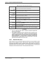
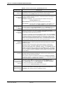
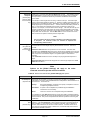
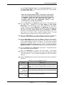
FEATURE
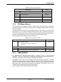
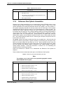
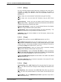
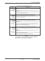
Calibration
Setting3
DESCRIPTION
See <Calibration Setting1>.
(optional
text/numeric entry)
Calibration
Setting4
See <Calibration Setting1>.
(optional
text/numeric entry)
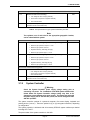
Record Last Edited
Date
The date of the last edit of the device. This field is used for display purposes only. GFS
Tools automatically updates this field when changes are saved.
(display only)
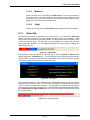
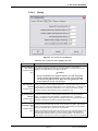
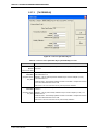
5.5.3.3
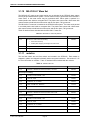
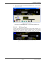
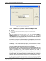
[Communications] Tab
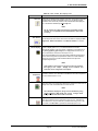
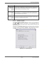
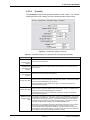
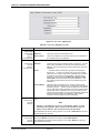
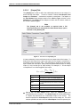
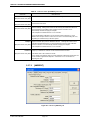
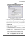
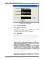
Select the desired data acquisition type and enter the settings appropriate for the
selection. By default, GFS Tools will perform all communications with the device
following the data acquisition type specified. Automated remote interfaces such
as IEEE-488 and RS232 require remote commands to be setup for each raw
output or raw set of the device.
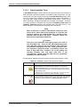
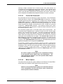
To use GFS Tools features correctly, the [Communications] tab settings should
always correspond to the actual output of the device, not of a support device that
may be required. For example, for a DUT that outputs a voltage the remote
interface of the DMM used to measure voltage should NOT be specified here.
Rather, select <Other Device> for <Data Acquisition Type> of the DUT and
setup the DMM separately using the Support Device Definition Editor. On the
[Communications Tab] of the DMM’s setup, specify the remote interface to the
DMM with a Final Output of Voltage. The DUT raw output source must be set to
<Voltage Measurement>. When GFS Tools tests this DUT, it will identify it as
having a voltage output and use the DMM to read the voltage.
This
implementation allows the DMM to be used at other times in GFS Tools to read
voltage or other signals without redefining the remote interface for each use. It
also simplifies changes related to the DMM since it only needs to be changed in
its Support Device Definition, not for each DUT that uses it.
There are occasions in which a support device is dedicated to a specific
measurement or control device. For example, a DUT may be “married to” a specific
signal conditioner. In this case, the signal conditioner can be considered part of the
DUT included in the DUT Definition. Therefore, the remote commands for the
conditioner should be specified with the DUT Definition.
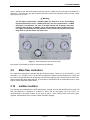
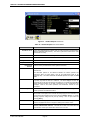
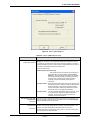
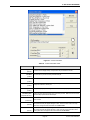
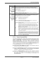
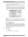
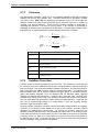
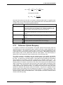
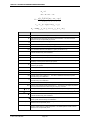
Figure 75. DUT Definition Editor [Communications] Tab
Page 121
© 2011 Fluke Calibration