1
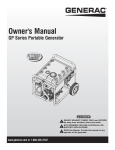
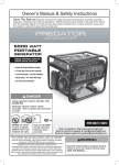
Owner's Manual Portable Generator DEADLY EXHAUST FUMES! ONLY use OUTSIDE far away from windows, doors and vents! NOT INTENDED FOR USE IN CRITICAL LIFE SUPPORT APPLICATIONS. SAVE this Manual. Provide this manual to any operator of the generator. 1-855-GEN-INFO or www.honeywellgenerators.com Table of Contents Introduction............................................................. 1 Maintenance ......................................................... 12 Read this Manual Thoroughly ................................. 1 3.1 Performing Scheduled Maintenance .............................12 3.2 Maintenance Schedule .................................................13 3.3 Product Specifications..................................................13 3.4 General Recommendations...........................................13 Safety Rules ........................................................... 1 Standards Index .............................................................3 3.5 Service Air Filter ...........................................................15 General Information ................................................ 4 3.6 Valve Clearance............................................................15 1.1 Unpacking ......................................................................4 3.7 General ........................................................................16 1.2 Assembly .......................................................................4 3.8 Long Term Storage .......................................................16 1.3 Emissions Information....................................................5 3.9 Other Storage Tips .......................................................16 Operation ................................................................ 6 2.1 Know the Generator .......................................................6 2.2 Connection Plugs ...........................................................7 2.3 How to Use the Generator ..............................................8 2.4 Don’t Overload the Generator..........................................9 2.5 Wattage Reference Guide ...............................................9 2.6 Before Starting the Generator .......................................10 2.7 Starting Pull Start Engines............................................11 2.8 Starting Electric Start Engines ......................................11 2.9 Stopping the Engine .....................................................12 Troubleshooting .................................................... 17 4.1 Troubleshooting Guide ..................................................17 Warranty ............................................................... 18 2.10 Low Oil Level Shutdown System ..................................12 2.11 Charging the Battery (Electric Start Units Only).............12 WARNING! 'EPMJSVRME4VSTSWMXMSR Engine exhaust and some of its constituents are known to the state of California to cause cancer, birth defects, and other reproductive harm. WARNING! 'EPMJSVRME4VSTSWMXMSR This product contains or emits chemicals known to the state of California to cause cancer, birth defects, and other reproductive harm. Introduction Thank you for purchasing this Honeywell model portable generator by Generac Power Systems, Inc. This model is a compact, high performance, air-cooled, engine driven generator designed to supply electrical power to operate electrical loads where no utility power is available or in place of utility due to a power outage. If any portion of this manual is not understood, contact the nearest Authorized Dealer for starting, operating and servicing procedures. The operator is responsible for proper and safe use of the equipment. We strongly recommend that the operator read this manual and thoroughly understand all instructions before using the equipment. We also strongly recommend instructing other users to properly start and operate the unit. This prepares them if they need to operate the equipment in an emergency. The generator can operate safely, efficiently and reliably only if it is properly located, operated and maintained. Before operating or servicing the generator: Become familiar with and strictly adhere to all local, state and national codes and regulations. Study all safety warnings in this manual and on the product carefully. Become familiar with this manual and the unit before use. The manufacturer cannot anticipate every possible circumstance that might involve a hazard. The warnings in this manual, and on tags and decals affixed to the unit are, therefore, not all inclusive. If using a procedure, work method or operating technique that the manufacturer does not specifically recommend, ensure that it is safe for others. Also make sure the procedure, work method or operating technique utilized does not render the generator unsafe. THE INFORMATION CONTAINED HEREIN WAS BASED ON MACHINES IN PRODUCTION AT THE TIME OF PUBLICATION. GENERAC RESERVES THE RIGHT TO MODIFY THIS MANUAL AT ANY TIME. Throughout this publication, and on tags and decals affixed to the generator, DANGER, WARNING, CAUTION and NOTE blocks are used to alert personnel to special instructions about a particular operation that may be hazardous if performed incorrectly or carelessly. Observe them carefully. Their definitions are as follows: INDICATES A HAZARDOUS SITUATION OR ACTION WHICH, IF NOT AVOIDED, WILL RESULT IN DEATH OR SERIOUS INJURY. Indicates a hazardous situation or action which, if not avoided, could result in death or serious injury. Indicates a hazardous situation or action which, if not avoided, could result in minor or moderate injury. NOTE: Notes contain additional information important to a procedure and will be found within the regular text body of this manual. These safety warnings cannot eliminate the hazards that they indicate. Common sense and strict compliance with the special instructions while performing the action or service are essential to preventing accidents. Four commonly used safety symbols accompany the DANGER, WARNING and CAUTION blocks. The type of information each indicates is as follows: This symbol points out important safety information that, if not followed, could endanger personal safety and/or property of others. This symbol points out potential explosion hazard. This symbol points out potential fire hazard. This symbol points out potential electrical shock hazard. GENERAL HAZARDS NEVER operate in an enclosed area, in a vehicle, or indoors EVEN IF doors and windows are open. For safety reasons, the manufacturer recommends that the maintenance of this equipment is carried out by an Authorized Dealer. Inspect the generator regularly, and contact the nearest Authorized Dealer for parts needing repair or replacement. Operate generator only on level surfaces and where it will not be exposed to excessive moisture, dirt, dust or corrosive vapors. Keep hands, feet, clothing, etc., away from drive belts, fans, and other moving parts. Never remove any fan guard or shield while the unit is operating. Certain parts of the generator get extremely hot during operation. Keep clear of the generator until it has cooled to avoid severe burns. Do NOT operate the generator in the rain. Do not alter the construction of the generator or change controls which might create an unsafe operating condition. Never start or stop the unit with electrical loads connected to receptacles AND with connected devices turned ON. Start the engine and let it stabilize before connecting electrical loads. Disconnect all electrical loads before shutting down the generator. Do not insert objects through the unit’s cooling slots. When working on this equipment, remain alert at all times. Never work on the equipment when physically or mentally fatigued. 1 Safety Rules Never use the generator or any of its parts as a step. Stepping on the unit can stress and break parts, and may result in dangerous operating conditions from leaking exhaust gases, fuel leakage, oil leakage, etc. On electric start models, disconnect the POSITIVE (+) battery cable from the engine starter OR the NEGATIVE (-) battery cable from the battery terminal, whichever is easier, before transporting the generator. NOTE: This generator may be equipped with a spark arrestor muffler. The spark arrestor must be maintained in effective working order by the owner/ operator. In the State of California, a spark arrestor is required by law (Section 4442 of the California Public Resources Code). Other states may have similar laws. Federal laws apply on federal lands. EXHAUST & LOCATION HAZARDS • Never operate in an enclosed area or indoors! NEVER use in the home, in a vehicle, or in partly enclosed areas such as garages, EVEN IF doors and windows are open! ONLY use outdoors and far from open windows, doors, vents, and in an area that will not accumulate deadly exhaust. ELECTRICAL HAZARDS The generator produces dangerously high voltage when in operation. Avoid contact with bare wires, terminals, connections, etc., while the unit is running, even on equipment connected to the generator. Ensure all appropriate covers, guards and barriers are in place before operating the generator. Never handle any kind of electrical cord or device while standing in water, while barefoot or while hands or feet are wet. DANGEROUS ELECTRICAL SHOCK MAY RESULT. The National Electric Code (NEC) requires the frame and external electrically conductive parts of the generator be properly connected to an approved earth ground. Local electrical codes may also require proper grounding of the generator. Consult with a local electrician for grounding requirements in the area. Use a ground fault circuit interrupter in any damp or highly conductive area (such as metal decking or steel work). Do not use worn, bare, frayed or otherwise damaged electrical cord sets with the generator. Before performing any maintenance on the generator, disconnect the engine starting battery (if equipped) to prevent accidental start up. Disconnect the cable from the battery post indicated by a NEGATIVE, NEG or (–) first. Reconnect that cable last. In case of accident caused by electric shock, immediately shut down the source of electrical power. If this is not possible, attempt to free the victim from the live conductor. AVOID DIRECT CONTACT WITH THE VICTIM. Use a non-conducting implement, such as a rope or board, to free the victim from the live conductor. If the victim is unconscious, apply first aid and get immediate medical help. FIRE HAZARDS The engine exhaust fumes contain carbon monoxide, which you cannot see or smell. This poisonous gas, if breathed in sufficient concentrations, can cause unconsciousness or even death. Adequate, unobstructed flow of cooling and ventilating air is critical to correct generator operation. Do not alter the installation or permit even partial blockage of ventilation provisions, as this can seriously affect safe operation of the generator. The generator MUST be operated outdoors. This exhaust system must be properly maintained. Do nothing that might render the exhaust system unsafe or in noncompliance with any local codes and/or standards. Always use a battery operated carbon monoxide alarm indoors, installed according to the manufacturers instructions. If you start to feel sick, dizzy, or weak after the generator has been running, move to fresh air IMMEDIATELY. See a doctor, as you could have carbon monoxide poisoning. 2 • Gasoline is highly FLAMMABLE and its vapors are EXPLOSIVE. Do not permit smoking, open flames, sparks or heat in the vicinity while handling gasoline. Never add fuel while unit is running or hot. Allow engine to cool completely before adding fuel. • Never fill fuel tank indoors. Comply with all laws regulating storage and handling of gasoline. • Do not overfill the fuel tank. Always allow room for fuel expansion. If tank is over-filled, fuel can overflow onto a hot engine and cause FIRE or an EXPLOSION. Never store generator with fuel in tank where gasoline vapors might reach an open flame, spark or pilot light (as on a furnace, water heater or clothes dryer). FIRE or EXPLOSION may result. Allow unit to cool entirely before storage. Wipe up any fuel or oil spills immediately. Ensure that no combustible materials are left on or near the generator. Keep the area surrounding the generator clean and free from debris and keep a clearance of five (5) feet on all side to allow for proper ventilation of the generator. Safety Rules Do not insert objects through the unit’s cooling slots. • Do not operate the generator if connected electrical devices overheat, if electrical output is lost, if engine or generator sparks or if flames or smoke are observed while unit is running. Keep a fire extinguisher near the generator at all times. MODEL NO: SERIAL NO: Unit ID Location 1. National Fire Protection Association (NFPA) 70: The NATIONAL ELECTRIC CODE (NEC) available from www.nfpa.org 2. National Fire Protection Association (NFPA) 5000: BUILDING CONSTRUCTION AND SAFETY CODE available from www. nfpa.org 3. International Building Code available from www.iccsafe.org 4. Agricultural Wiring Handbook available from www.rerc.org , Rural Electricity Resource Council P.O. Box 309 Wilmington, OH 45177-0309 5. ASAE EP-364.2 Installation and Maintenance of Farm Standby Electric Power available from www.asabe.org, American Society of Agricultural & Biological Engineers 2950 Niles Road, St. Joseph, MI 49085 This list is not all inclusive. Check with the Authority Having Local Jurisdiction (AHJ) for any local codes or standards which may be applicable to your jurisdiction. 3 General Information Remove all packaging material. Remove separate accessory box. Remove the generator from carton. Check all contents. If any parts are missing or damaged, locate an authorized dealer at 1-855-GEN-INFO. 1-Owner’s manual 1-Bottle of Oil SAE 30 3-Product Registration Cards (English, Spanish, French) 1-Oil Funnel 4-Carriage Bolts (A) 4-Acorn Nuts (B) 2-Small Washers (C) 2-Rubber Feet (D) 2-Foot Brackets (E) 2-M8-1.25 x 25.4 (F) 8-M8-1.25 x 16 (G) 10-M8 Nuts (H) 1-Axle (J) 1-Axle Bracket (K) 2-Wheels (L) 2-Large Washers (M) 2-Hair Pins (N) 1-Battery Charger (Electric start models) 6. Use four short bolts (G) and four nuts (H) to secure the axle (J) & bracket (K) to the frame. 7. Slide wheel (L) and washer (M) onto axle (J). Secure parts with pin (N). 8. Repeat steps 6 & 7 for the opposite wheel. Figure 1A Handle Assembly Figure 1B Foot Assembly The generator requires some assembly prior to using it. If problems arise when assembling the generator, please call the Generator Helpline at 1-855-GEN-INFO. The wheels are designed to greatly improve the portability of the generator. You will need the following tools to properly install the accessory kit: Ratchet, a 10mm socket and a 13mm socket 10mm box wrench Refer to the instructions below and figures 1A, 1B, and 1C to install the handles, feet, and wheels. Note: the handle components are already pre-assembled from the factory. 1. Install the handle assembly to the frame by using bolts (A) and nuts (B). 2. Repeat step one for opposite handle. 3. Place washer (C) inside rubber foot (D). Secure parts to bracket (E) with bolt (F) and nut (H). 4. Install foot assembly to the frame using the short bolts (G) and nuts (H). 5. Repeat steps 3 & 4 for other foot. 4 * + ) ( ' , General Information Figure 1C Wheel Assembly The Environmental Protection Agency (and California Air Resource Board for generators certified to CA standards) requires that this generator comply with exhaust and evaporative emission standards. Locate the emissions compliance decal on the engine to determine what standards the generator meets, and to determine which warranty applies. This generator is certified to operate on gasoline. The emission control system includes the following components (if equipped): Air Induction System – Intake Pipe / Manifold – Air Cleaner Fuel System – – – – – Carburetor Fuel Tank / Cap Fuel Lines Evaporative Vent Lines Carbon Canister Ignition System – Spark Plug – Ignition Module Exhaust System – – – – Exhaust Manifold Muffler Pulsed Air Valve Catalyst The unit has been deliberately shipped with the battery cables disconnected. You will need a 10mm wrench to secure the battery cables. To connect the battery (see Figure 14 for connection details): 1. Cut off cable ties securing battery cables. 2. First, connect the red cable to the positive (+) battery terminal with the supplied bolt. 3. Connect the black cable to the negative (-) battery terminal with the supplied bolt. 4. Make sure all connections are secure. Slide the rubber boots over the terminals and connection hardware. NOTE: If the battery is unable to start the engine, charge it with the 12V charger included in the accessory box (see the "Charging a Battery" section for details). 5 Operation Figure 2B - Control Panel (CARB Models) Read the Owner’s Manual and Safety Rules before operating this generator. Compare the generator to Figures 2 through 4 to become familiarized with the locations of various controls and adjustments. Save this manual for future reference. 1. 120 Volt AC, 20 Amp, Duplex Receptacle – Supplies electrical power for the operation of 120 Volt AC, 20 Amp, single-phase, 60 Hz electrical lighting, appliance, tool and motor loads (CARB models are equipped with GFCI outlets). 2. 120/240 Volt AC, 30 Amp Locking Receptacle – Supplies electrical power for the operation of 120 and/or 240 Volt AC, 30 Amp, single-phase, 60 Hz, electrical lighting, appliance, tool and motor loads. 3. Circuit Breakers (AC) – Each receptacle is provided with a circuit breaker to protect the generator against electrical overload. 4. Oil Drain – Use to drain engine oil. 5. Air Filter – Filters intake air as it is drawn into the engine. 6. Choke Knob – Used when starting a cold engine. 7. Fuel Tank – See generator Specifications for tank capacity. 8. Grounding Lug – Ground the generator to an approved earth ground here. See "Grounding the Generator" for details. 9. Run/Stop Switch – Controls the operation of the generator (pull start models). 9A. Start Switch – Used to start engine from the starter motor (electric start models only). 10. Muffler – Quiets the engine. 11. Handles – Pivot and retract for storage. Press the springloaded button to move handles. 12. Gas Cap – Fuel fill location. 13. Fuel Gauge – Shows fuel level in tank. 14. Oil Fill – Add oil here. 15. Recoil Starter – Use to start engine manually. 16. Fuel Shut Off – Valve between fuel tank and carburetor. Figure 2A - Control Panel (49 State CSA Models) 6 17. Battery Charger Input – This receptacle allows the capability to recharge the 12 volt DC storage battery provided with the 12 Volt Adaptor Plug Charger which is included in the Accessory Box. Located behind the battery charger input is a 1.50 Amp in-line fuse which is inside the control panel to protect the battery (electric start models only). 18. Battery – Powers the electric starter (electric start models only). Figure 3 - Generator Controls Operation Figure 4 - Generator Controls This is a 120 Volt outlet protected against overload by a 20 Amp push-to-reset circuit breaker (Figure 6). Use each socket to power 120 Volt AC, single phase, 60 Hz electrical loads requiring up to a combined 2400 watts (2.4 kW) or 20 Amps of current. Use only high quality, well-insulated, 3-wire grounded cord sets rated for 125 Volts at 20 Amps (or greater). Keep extension cords as short as possible to prevent voltage drop and possible overheating of wires. Figure 6 - 120 Volt AC, 20 Amp, GFCI Duplex Receptacle This is a 120 Volt outlet protected against overload by a 20 Amp push-to-reset circuit breaker (Figure 5). Use each socket to power 120 Volt AC, single phase, 60 Hz electrical loads requiring up to a combined 2400 watts (2.4 kW) or 20 Amps of current. Use only high quality, well-insulated, 3-wire grounded cord sets rated for 125 Volts at 20 Amps (or greater). Use a NEMA L14-30 plug with this receptacle (rotate to lock/ unlock). Connect a suitable 4-wire grounded cord set to the plug and to the desired load. The cord set should be rated for 250 Volts AC at 30 Amps (or greater) (Figure 7). Figure 7 - 120/240 VAC, 30 Amp Receptacle Keep extension cords as short as possible, preferably less than 15 feet long, to prevent voltage drop and possible overheating of wires. Figure 5 - 120 Volt AC, 20 Amp, Duplex Receptacle Use this receptacle to operate 120 Volt AC, 60 Hz, single phase loads requiring up to 3600 watts (3.6 kW) of power at 30 Amps or 240 Volt AC, 60 Hz, single phase loads requiring up to 7200 watts (7.2 kW) of power at 30 Amps. The outlet is protected by a 2-pole toggle switch circuit breaker. 7 Operation See the "To Start the Engine" section for how to safely start and stop the generator and how to connect and disconnect loads. If there are any problems operating the generator, please call the generator helpline at 1-888-436-3722. Never operate in an enclosed area or indoors! NEVER use in the home, in a vehicle, or in partly enclosed areas such as garages, EVEN IF doors and windows are open! ONLY use outdoors and far from open windows, doors, vents, and in an area that will not accumulate deadly exhaust. The engine exhaust fumes contain carbon monoxide, which you cannot see or smell. This poisonous gas, if breathed in sufficient concentrations, can cause unconsciousness or even death. Adequate, unobstructed flow of cooling and ventilating air is critical to correct generator operation. Do not alter the installation or permit even partial blockage of ventilation provisions, as this can seriously affect safe operation of the generator. The generator MUST be operated outdoors. This exhaust system must be properly maintained. Do nothing that might render the exhaust system unsafe or in noncompliance with any local codes and/or standards. This generator has an equipment ground that connects the generator frame components to the ground terminals on the AC output receptacles (see NEC 250.34 (A) for explanation). This allows the generator to be used as a portable without grounding the frame of the generator as specified in NEC 250.34. There may be Federal or State Occupational Safety and Health Administration (OSHA) regulations, local codes, or ordinances that apply to the intended use of the generator. Please consult a qualified electrician, electrical inspector, or the local agency having jurisdiction: In some areas, generators are required to be registered with local utility companies. If the generator is used at a construction site, there may be additional regulations which must be observed. When connecting directly to a building's electrical system, it is recommended that a manual transfer switch is used. Connections for a portable generator to a building's electrical system must be made by a qualified electrician and in strict compliance with all national and local electrical codes and laws. Figure 8 - Grounding the Generator Always use a battery operated carbon monoxide alarm indoors, installed according to the manufacturer's instructions. Grounding 8 Operation DO NOT connect 240 Volt loads to 120 Volt receptacles. DO NOT connect 3-phase loads to the generator. DO NOT connect 50 Hz loads to the generator. Let engine stabilize and warm up for a few minutes after starting. Plug in and turn on the desired 120 or 240 Volt AC, single phase, 60 Hz electrical loads. Add up the rated watts (or amps) of all loads to be connected at one time. This total should not be greater than (a) the rated wattage/amperage capacity of the generator or (b) circuit breaker rating of the receptacle supplying the power. See "Don't Overload the Generator". Overloading a generator in excess of its rated wattage capacity can result in damage to the generator and to connected electrical devices. Observe the following to prevent overloading the unit: Add up the total wattage of all electrical devices to be connected at one time. This total should NOT be greater than the generator's wattage capacity. The rated wattage of lights can be taken from light bulbs. The rated wattage of tools, appliances and motors can usually be found on a data label or decal affixed to the device. If the appliance, tool or motor does not give wattage, multiply volts times ampere rating to determine watts (volts x amps = watts). Some electric motors, such as induction types, require about three times more watts of power for starting than for running. This surge of power lasts only a few seconds when starting such motors. Make sure to allow for high starting wattage when selecting electrical devices to connect to the generator: 1. Figure the watts needed to start the largest motor. 2. Add to that figure the running watts of all other connected loads. The Wattage Reference Guide is provided to assist in determining how many items the generator can operate at one time. NOTE: All figures are approximate. See data label on appliance for wattage requirements. Device . . . . . . . . . . . . . . . . . . . . . . . . . . . . . . . . . . . Running Watts *Air Conditioner (12,000 Btu) . . . . . . . . . . . . . . . . . . . . . . . . . . 1700 *Air Conditioner (24,000 Btu) . . . . . . . . . . . . . . . . . . . . . . . . . . 3800 *Air Conditioner (40,000 Btu) . . . . . . . . . . . . . . . . . . . . . . . . . . 6000 Battery Charger (20 Amp). . . . . . . . . . . . . . . . . . . . . . . . . . . . . . 500 Belt Sander (3") . . . . . . . . . . . . . . . . . . . . . . . . . . . . . . . . . . . . 1000 Chain Saw . . . . . . . . . . . . . . . . . . . . . . . . . . . . . . . . . . . . . . . . 1200 Circular Saw (6-1/2") . . . . . . . . . . . . . . . . . . . . . . . . . . .800 to 1000 *Clothes Dryer (Electric) . . . . . . . . . . . . . . . . . . . . . . . . . . . . . 5750 *Clothes Dryer (Gas) . . . . . . . . . . . . . . . . . . . . . . . . . . . . . . . . . 700 *Clothes Washer . . . . . . . . . . . . . . . . . . . . . . . . . . . . . . . . . . . 1150 Coffee Maker . . . . . . . . . . . . . . . . . . . . . . . . . . . . . . . . . . . . . . 1750 *Compressor (1 HP). . . . . . . . . . . . . . . . . . . . . . . . . . . . . . . . . 2000 *Compressor (3/4 HP) . . . . . . . . . . . . . . . . . . . . . . . . . . . . . . . 1800 *Compressor (1/2 HP) . . . . . . . . . . . . . . . . . . . . . . . . . . . . . . . 1400 Curling Iron. . . . . . . . . . . . . . . . . . . . . . . . . . . . . . . . . . . . . . . . . 700 *Dehumidifier . . . . . . . . . . . . . . . . . . . . . . . . . . . . . . . . . . . . . . . 650 Disc Sander (9") . . . . . . . . . . . . . . . . . . . . . . . . . . . . . . . . . . . . 1200 Edge Trimmer . . . . . . . . . . . . . . . . . . . . . . . . . . . . . . . . . . . . . . . 500 Electric Blanket . . . . . . . . . . . . . . . . . . . . . . . . . . . . . . . . . . . . . . 400 Electric Nail Gun . . . . . . . . . . . . . . . . . . . . . . . . . . . . . . . . . . . . 1200 Electric Range (per element) . . . . . . . . . . . . . . . . . . . . . . . . . . . 1500 Electric Skillet . . . . . . . . . . . . . . . . . . . . . . . . . . . . . . . . . . . . . . 1250 *Freezer . . . . . . .. . . . . . . . . . . . . . . . . . . . . . . . . . . . . . . . . . . ..700 *Furnace Fan (3/5 HP) . . . . . . . . . . . . . . . . . . . . . . . . . . . . . . . . 875 *Garage Door Opener . . . . . . . . . . . . . . . . . . . . . . . . . . . .500 to 750 Hair Dryer. . . . . . . . . . . . . . . . . . . . . . . . . . . . . . . . . . . . . . . . . 1200 Hand Drill . . . . . . . . . . . . . . . . . . . . . . . . . . . . . . . . . . . .250 to 1100 Hedge Trimmer . . . . . . . . . . . . . . . . . . . . . . . . . . . . . . . . . . . . . . 450 Impact Wrench . . . . . . . . . . . . . . . . . . . . . . . . . . . . . . . . . . . . . . 500 Iron. . . . . . . . . . . . . . . . . . . . . . . . . . . . . . . . . . . . . . . . . . . . . . 1200 *Jet Pump . . . . . . . . . . . . . . . . . . . . . . . . . . . . . . . . . . . . . . . . . 800 Lawn Mower. . . . . . . . . . . . . . . . . . . . . . . . . . . . . . . . . . . . . . . 1200 Light Bulb . . . . . . . . . . . . . . . . . . . . . . . . . . . . . . . . . . . . . . . . . . 100 Microwave Oven . . . . . . . . . . . . . . . . . . . . . . . . . . . . . . .700 to 1000 *Milk Cooler . . . . . . . . . . . . . . . . . . . . . . . . . . . . . . . . . . . . . . . 1100 Oil Burner on Furnace . . . . . . . . . . . . . . . . . . . . . . . . . . . . . . . . . 300 Oil Fired Space Heater (140,000 Btu) . . . . . . . . . . . . . . . . . . . . . 400 Oil Fired Space Heater (85,000 Btu) . . . . . . . . . . . . . . . . . . . . . . 225 Oil Fired Space Heater (30,000 Btu) . . . . . . . . . . . . . . . . . . . . . . 150 *Paint Sprayer, Airless (1/3 HP) . . . . . . . . . . . . . . . . . . . . . . . . . 600 Paint Sprayer, Airless (handheld). . . . . . . . . . . . . . . . . . . . . . . . . 150 Radio . . . . . . . . . . . . . . . . . . . . . . . . . . . . . . . . . . . . . . . . .50 to 200 *Refrigerator. . . . . . . . . . . . . . . . . . . . . . . . . . . . . . . . . . . . . . . . 700 Slow Cooker . . . . . . . . . . . . . . . . . . . . . . . . . . . . . . . . . . . . . . . . 200 *Submersible Pump (1-1/2 HP) . . . . . . . . . . . . . . . . . . . . . . . . 2800 *Submersible Pump (1 HP) . . . . . . . . . . . . . . . . . . . . . . . . . . . 2000 *Submersible Pump (1/2 HP) . . . . . . . . . . . . . . . . . . . . . . . . . . 1500 *Sump Pump . . . . . . . . . . . . . . . . . . . . . . . . . . . . . . . . .800 to 1050 *Table Saw (10") . . . . . . . . . . . . . . . . . . . . . . . . . . . . .1750 to 2000 Television . . . . . . . . . . . . . . . . . . . . . . . . . . . . . . . . . . . . .200 to 500 Toaster . . . . . . . . . . . . . . . . . . . . . . . . . . . . . . . . . . . . .1000 to 1650 Weed Trimmer . . . . . . . . . . . . . . . . . . . . . . . . . . . . . . . . . . . . . . 500 * Allow 3 times the listed watts for starting these devices. 9 Operation Prior to operating the generator, engine oil and gasoline will need to be added, as follows: Never fill fuel tank indoors. Avoid spilling gasoline on hot engine. Allow engine to cool entirely before adding fuel. Never fill fuel tank when engine is running or hot. DO NOT light a cigarette or smoke when filling the fuel tank. Gasoline is highly flammable and its vapors are explosive. All oil should meet minimum American Petroleum Institute (API) Service Class SJ, SL or better. Use no special additives. Select the oil's viscosity grade according to the expected operating temperature (also see chart). Above 40° F, use SAE 30 Below 40° F and down to 10° F, use 10W-30 Below 10° F, use synthetic 5W-30 7% ) ; 7] RXLI XMG ; 1. 2. 3. 4. 5. Any attempt to crank or start the engine before it has been properly serviced with the recommended oil may result in an engine failure. Place generator on a level surface (not to exceed 15° in any direction). Clean area around oil fill and remove oil fill cap. Slowly fill engine with oil. Stop filling occasionally to check oil level. Oil level is full when level is up to the threads of the oil fill plug. Install oil fill plug and finger tighten securely. Check engine oil level before starting each time thereafter. 1. 2. 3. 4. Do not overfill the fuel tank. Always leave room for fuel expansion. If the fuel tank is overfilled, fuel can over flow onto a hot engine and cause fire or an explosion. Wipe up any spilled fuel immediately. Use regular UNLEADED gasoline with the generator engine. Do not use premium gasoline. Do not mix oil with gasoline. Clean area around fuel fill cap, remove cap. Slowly add unleaded regular gasoline to fuel tank. Fill to bottom of screen filter. Be careful not to overfill (Figure 9). Install fuel cap and wipe up any spilled gasoline. IMPORTANT: It is important to prevent gum deposits from forming in fuel system parts such as the carburetor, fuel hose or tank during storage. Alcohol-blended fuels (called gasohol, ethanol or methanol) can attract moisture, which leads to separation and formation of acids during storage. Acidic gas can damage the fuel system of an engine while in storage. To avoid engine problems, the fuel system should be emptied before storage of 30 days or longer. See the "Storage" section. Never use engine or carburetor cleaner products in the fuel tank as permanent damage may occur. Figure 9 - Fuel Tank *YIP8ERO *YIP 10 (3238*MPP%FSZI0MT Maintenance 1. 2. 3. 4. 5. 6. 7. Never start or stop engine with electrical devices plugged into the receptacles AND devices turned on. Unplug all electrical loads from the unit's receptacles before starting the engine. Make sure the unit is in a level position (not to exceed 15° in any direction). OPEN the Fuel Shut-off Valve (Figure 10). Turn engine RUN/STOP switch to ON position (Figure 2A). Slide engine choke to the LEFT to FULL CHOKE position (Figure 11). To start engine, firmly grasp the recoil handle and pull slowly until increased resistance is felt. Pull rapidly up and away. When engine starts, move choke knob to 1/2-CHOKE position until engine runs smoothly and then fully into RUN position. If engine falters, move choke back out to 1/2-CHOKE position until engine runs smoothly and then to RUN position. NOTE: If engine fires, but does not continue to run, move choke lever to FULL CHOKE and repeat starting instructions. Figure 10 - Fuel Shut-off Valve IMPORTANT: Do not overload the generator. Also, do not overload individual panel receptacles. These outlets are protected against overload with push-to-reset-type circuit breakers. If amperage rating of any circuit breaker is exceeded, that breaker opens and electrical output to that receptacle is lost. Read “Don’t Overload the Generator” carefully. 1. 2. 3. 4. 5. 6. Never start or stop engine with electrical devices plugged into the receptacles AND devices turned on. Unplug all electrical loads from the unit's receptacles before starting the engine. Make sure the unit is in a level position (not to exceed 15° in any direction). Open the fuel shut-off valve (Figures 10). Move engine CHOKE knob outward to FULL CHOKE position (Figure 11). To start engine, press and hold the Start/Run/Stop switch in the “Start” position. The engine will crank and attempt to start. When the engine starts, release the switch to the run position. When the engine starts, move choke knob to “1/2 Choke” position until the engine runs smoothly and then fully in to the “Run” position. If engine falters, move choke knob back out to “1/2 Choke” position until the engine runs smoothly and then to “Run” position. This generator is also equipped with a manual recoil starter which may be used if the battery is discharged. NOTE: The switch must be in the RUN position. Use one of the generator’s receptacle outlets along with the included battery charger to charge the battery while the generator is running. Figure 11 - Choke Position To start manually, firmly grasp the recoil handle and pull slowly until increased resistance is felt. Pull rapidly up and away to start engine. Then follow the same choke sequence. NOTE: CHOKE LEVER LEFT = CHOKE (START) RIGHT = RUN If engine fires, but does not continue to run, move choke lever to FULL CHOKE and repeat starting instructions. IMPORTANT: Do not overload the generator. Also, do not overload individual panel receptacles. These outlets are protected against overload with push-to-reset-type circuit breakers. If amperage rating of any circuit breaker is exceeded, that breaker opens and electrical output to that receptacle is lost. Read “Don’t Overload the Generator” carefully. 11 Maintenance NOTE: 1. Shut off all loads, then unplug the electrical loads from generator panel receptacles. Never start or stop the engine with electrical devices plugged in and turned on. 2. Let engine run at no-load for several minutes to stabilize the internal temperatures of engine and generator. 3. Move Run/Stop switch to OFF position. 4. Close fuel valve. The engine is equipped with a low oil level sensor that shuts down the engine automatically when the oil level drops below a specified level. If the engine shuts down by itself and the fuel tank has enough gasoline, check engine oil level. The battery shipped with the generator has been fully charged. A battery may lose some of its charge when not in use for prolonged periods of time. If the battery is unable to crank the engine, plug in the 12V charger included in the accessory box (see section "Charging the Battery"). RUNNING THE GENERATOR DOES NOT CHARGE THE BATTERY. Use battery charger plug to keep the battery charged and ready for use. Battery charging should be done in a dry location. 1. Plug charger into “Battery Charger Input” jack, located on the control panel. Plug wall receptacle end of the battery charger into a 120 Volt AC wall outlet (Figure 12). 2. Unplug battery charger from wall outlet and control panel jack when generator is going to be in use. NOTE: If the system senses a low oil level during operation, the engine shuts down. The engine will not run until the oil has been refilled to the proper level. Do not use the battery charger for more than 48 hours at one charge. Figure 12 - Battery Charger Jack &%88)6= Storage batteries give off explosive hydrogen gas while recharging. An explosive mixture will remain around the battery for a long time after it has been charged. The slightest spark can ignite the hydrogen and cause an explosion. Such an explosion can shatter the battery and cause blindness or other serious injury. Do not permit smoking, open flame, sparks or any other source of heat around a battery. Wear protective goggles, rubber apron and rubber gloves when working around a battery. Battery electrolyte fluid is an extremely corrosive sulfuric acid solution that can cause severe burns. If spill occurs flush area with clear water immediately. 12 ',%6+)6 -2498 It is important to perform service as specified in the Maintenance Schedule for proper generator operation, and to ensure that the generator complies with the applicable emission standards for the duration of its useful life. Service and repairs may be performed by any capable person or repair shop. Additionally, emissions critical maintenance must be performed as scheduled in order for the Emissions Warranty to be valid. Emissions critical maintenance consists of servicing the air filter and spark plugs in accordance with the Maintenance Schedule. Maintenance Follow the calendar intervals. More frequent service is required when operating in adverse conditions noted below. Check Oil Level Change Oil Check Valve Clearance Service Air Filter Replace Spark Plug At Each Use *Every 100 hours or Every Season ***Every Season ** Every 200 hours or Every Season Every Season Change oil after first 30 hours of operation then every season. * Change oil and oil filter every month when operating under heavy load or in high temperatures. ** Clean more often under dirty or dusty operating conditions. Replace air filter parts if they cannot be adequately cleaned. *** Check valve clearance and adjust if necessary after first 50 hours of operation and every 100 hours thereafter. 5.5 kW Rated Power ...........................................................................5.5 kW** Surge Power ...........................................................................6.8 kW** Rated AC Voltage ......................................................................120/240 Rated Max AC Load Current @ 240V ........................................................... 22.9 Amps** Current @120V ............................................................ 45.8 Amps** Rated Frequency ..................................................... 60 Hz @3600 RPM Phase ................................................................................ Single Phase 6.5 kW Rated Power ...........................................................................6.5 kW** Surge Power ...........................................................................8.1 kW** Rated AC Voltage ......................................................................120/240 Rated Max AC Load Current @ 240V ............................................................27.1 Amps** Current @120V ............................................................ 54.2 Amps** Rated Frequency ..................................................... 60 Hz @3600 RPM Phase ................................................................................ Single Phase 7.5 kW Rated Power ...........................................................................7.5 kW** Surge Power .......................................................................... 9.4 kW** Rated AC Voltage ......................................................................120/240 Rated Max AC Load Current @ 240V ............................................................31.3 Amps** Current @120V ............................................................ 62.5 Amps** Rated Frequency ..................................................... 60 Hz @3600 RPM Phase ................................................................................ Single Phase ** Maximum wattage and current are subject to, and limited by, such factors as fuel Btu content, ambient temperature, altitude, engine condition, etc.. Maximum power decreases about 3.5% for each 1,000 feet above sea level; and will also decrease about 1% for each 6° C (10° F) above 16° C (60° F) ambient temperature. 5.5 & 6.5 kW Displacement ............................................................................... 389cc Spark Plug Type ................................ NHSP LDF7TC or Champion N9YC Spark Plug Gap ............................. 0.028-0.031 inches (0.70-0.80 mm) Spark Plug Part Number..................................................... 0J00620106 Gasoline Capacity .........................................................5.8 U.S. Gallons Oil Type....................................See Chart in “Adding Engine Oil” Section Oil Capacity ....................................................................1 L (1.06 Qts.) Run Time (50% Load) ...................................................................9 hrs. 7.5 kW Displacement ............................................................................... 420cc Spark Plug Type ................................ NHSP LDF7TC or Champion N9YC Spark Plug Gap ....................................................0.030 inch (0.76 mm) Spark Plug Part Number..................................................... 0J00620106 Gasoline Capacity .........................................................5.8 U.S. Gallons Oil Type....................................See Chart in “Adding Engine Oil” Section Oil Capacity ....................................................................1 L (1.06 Qts.) Run Time (50% Load) ...................................................................8 hrs. The warranty of the generator does not cover items that have been subjected to operator abuse or negligence. To receive full value from the warranty, the operator must maintain the generator as instructed in this manual. Some adjustments will need to be made periodically to properly maintain the generator. All adjustments in the Maintenance section of this manual should be made at least once each season. Follow the requirements in the "Maintenance Schedule". NOTE: Once a year replace the spark plug and replace the air filter. A new spark plug and clean air filter assure proper fuel-air mixture and help the engine run better and last longer. Generator maintenance consists of keeping the unit clean and dry. Operate and store the unit in a clean dry environment where it will not be exposed to excessive dust, dirt, moisture or any corrosive vapors. Cooling air slots in the generator must not become clogged with snow, leaves, or any other foreign material. Check the cleanliness of the generator frequently and clean when dust, dirt, oil, moisture or other foreign substances are visible on its exterior surface. Never insert any object or tool through the air cooling slots, even if the engine is not running. 13 Maintenance NOTE: DO NOT use a garden hose to clean generator. Water can enter the engine fuel system and cause problems. In addition, if water enters the generator through cooling air slots, some water will be retained in voids and crevices of the rotor and stator winding insulation. Water and dirt buildup on the generator internal windings will eventually decrease the insulation resistance of these windings. Use a damp cloth to wipe exterior surfaces clean. A soft, bristle brush may be used to loosen caked on dirt, oil, etc. A vacuum cleaner may be used to pick up loose dirt and debris. Low pressure air (not to exceed 25 psi) may be used to blow away dirt. Inspect cooling air slots and openings on the generator. These openings must be kept clean and unobstructed. When working on the generator, always disconnect negative cable from battery. Also disconnect spark plug wire from spark plug and keep wire away from spark plug. See the “Before Starting the Generator” section for information on checking the oil level. The oil level should be checked before each use, or at least every eight hours of operation. Keep the oil level maintained. Change the oil after the first 30 hours of operation. Change the oil every 100 hours or every season thereafter. If running this unit under dirty or dusty conditions, or in extremely hot weather, change the oil more often. Hot oil may cause burns. Allow engine to cool before draining oil. Avoid prolonged or repeated skin exposure with used oil. Thoroughly wash exposed areas with soap. Use the following instructions to change the oil after the engine cools down: 1. Clean area around oil drain plug. 2. Remove oil drain plug from engine and oil fill plug to drain oil completely into a suitable container. 3. When oil has completely drained, install oil drain plug and tighten securely. 4. Fill engine with recommended oil. (See “Before Starting the Generator” for oil recommendations). 5. Wipe up any spilled oil. 6. Dispose of used oil at a proper collection center. 14 See Engine Specifications for recommended spark plug. Replace the plug once each year. This will help the engine start easier and run better. 1. Stop the engine and pull the spark plug wire off of the spark plug. 2. Clean the area around the spark plug and remove it from the cylinder head. 3. Set the spark plug's gap to 0.70-0.80 mm (0.028-0.031 in.). Install the correctly gapped spark plug into the cylinder head (Figure 13). Figure 13 - Spark Plug Gap NOTE: The battery shipped with the generator has been fully charged. A battery may lose some of its charge when not in use for prolonged periods of time. If the battery is unable to crank the engine, plug in the 12V charger included in the accessory box (see the Charging a Battery section). RUNNING THE GENERATOR DOES NOT CHARGE THE BATTERY. Refer to the Battery Cable Connection section. Figure 14 - Battery Connections Maintenance The engine will not run properly and may be damaged if using a dirty air filter. Clean or replace the air filter paper filter once a year. Clean or replace more often if operating under dusty conditions (Figure 15). To clean or replace paper air filter: 1. Remove air filter cover and remove paper filter. 2. Clean paper filter by tapping it gently on a solid surface. If the filter is too dirty, replace it with a new one. Dispose of the old filter properly. The air filter part number is 0G84420151. 3. Clean air filter cover, then insert new paper filter into the base of the air filter. Re-install air filter cover. NOTE: To order a new air filter, please contact the nearest authorized service center at 1-855-GEN-INFO. Clean and inspect the spark arrestor when the engine is at ambient temperature as follows: 1. Remove the spark arrestor screen from the muffler by loosening the clamp and removing the screw. 2. Inspect screen and replace if torn, perforated or otherwise damaged. DO NOT USE a defective screen. If screen is not damaged, clean it with commercial solvent. 3. Replace the spark arrestor and secure with the clamp and screw. NOTE: To order a new air filter or spark arrestor screen, please contact the nearest authorized service center at 1-800-333-1322. Figure 16 Spark Arrestor Screen Figure 15 - Air Filter KNOB TO OPEN AIR BOX The engine exhaust muffler has a spark arrestor screen. Inspect and clean the screen at least once each year (Figure 16). If unit is used regularly, inspect and clean more often. Intake — 0.15 ± 0.02mm (cold), (0.006" ± 0.0008" inches) Exhaust — 0.20 ± 0.02mm (cold) (0.008" ± 0.0008" inches) After the first 50 hours of operation, check the valve clearance in the engine and adjust if necessary. Important: If feeling uncomfortable about doing this procedure or the proper tools are not available, please take the generator to the nearest service center to have the valve clearance adjusted. This is a very important step to ensure longest life for the engine. If using the generator on any forest-covered, brush-covered or grass-covered unimproved land, it must be equipped with a spark arrestor. The spark arrestor must be maintained in good condition by the owner/operator. 15 15 Maintenance The generator should be started at least once every thirty days and be allowed to run at least 30 minutes. If this cannot be done and the unit must be stored for more than 30 days, use the following information as a guide to prepare it for storage. NEVER store engine with fuel in tank indoors or in enclosed, poorly ventilated areas where fumes may reach an open flame, spark or pilot light as on a furnace, water heater, clothes dryer or other gas appliance. Allow unit to cool entirely before storage. It is important to prevent gum deposits from forming in essential fuel system parts such as the carburetor, fuel hose or tank during storage. Also, experience indicates that alcohol-blended fuels (called gasohol, ethanol or methanol) can attract moisture, which leads to separation and formation of acids during storage. Acidic gas can damage the fuel system of an engine while in storage. To avoid engine problems, the fuel system should be emptied before storage of 30 days or longer, as follows: A quality fuel stabilizer should be added to the existing fuel per the manufacturers specifications. Drain fuel into approved container outdoors, away from open flame. Be sure engine is cool. Do not smoke. Start and run the engine for 10 - 15 minutes, after that time and while the unit is running, turn the fuel shut-off valve OFF and run until the engine stops from lack of fuel. Allow the engine to cool, then remove all gasoline from the fuel tank. Use a commercially available, non-conductive vacuum siphon. Drain oil from crankcase. Refill the crankcase with recommended grade oil. Remove spark plug and spray with a quality fogging agent, or pour about 1/2 ounce (15 ml) of engine oil into the cylinder. Cover spark plug hole with rag. Pull the recoil starter a couple times to lubricate the piston rings and cylinder bore. A fogging agent can also be used in the place of oil. 16 Avoid spray from spark plug hole when cranking engine. Install and tighten spark plug. Do not connect spark plug wire. Clean the generator's outer surfaces. Check that cooling air slots and openings on generator are open and unobstructed. Store the unit in a clean, dry place. Do not store gasoline from one season to another. Replace the gasoline can if it starts to rust. Rust and/or dirt in the gasoline will cause problems with the carburetor and fuel system. If possible, store the unit indoors and cover it to give protection from dust and dirt. BE SURE TO EMPTY THE FUEL TANK. If it is not practical to empty the fuel tank and the unit is to be stored for some time, use a commercially available fuel stabilizer added to the gasoline to increase the life of the gasoline. Start and run the engine for 10 - 15 minutes, after that time and while the unit is running, turn the fuel shut-off valve OFF and run until the engine stops from lack of fuel. Cover the unit with a suitable protective cover that does not retain moisture. NEVER cover the generator while engine and exhaust areas are warm. Troubleshooting PROBLEM CAUSE CORRECTION Engine is running, but no AC output is available. 1. 2. 3. 4. Circuit breaker is open. Poor connection or defective cord set. Connected device is bad. Fault in generator. 1. 2. 3. 4. Reset circuit breaker. Check and repair. Connect another device that is in good condition. Contact Authorized Service Facility. Engine runs well but bogs down when loads are connected. 1. 2. 3. 4. Short circuit in a connected load. Generator is overloaded. Engine speed is too slow. Shorted generator circuit. 1. 2. 3. 4. Disconnect shorted electrical load. See “Don’t Overload the Generator” . Contact Authorized Service Facility. Contact Authorized Service Facility. Engine will not start; or starts and runs rough. 1. Fuel Shut-off is OFF. 2. Dirty air filter. 3. Out of gasoline. 4. Stale gasoline. 5. Spark plug wire not connected to spark plug. 6. Bad spark plug. 7. Water in gasoline. 8. Over-choking. 9. Low oil level. 10. Excessive rich fuel mixture. 11. Intake valve stuck open or closed. 12. Engine has lost compression. 1. Turn Fuel Shut-off to ON. 2. Clean or replace air filter. 3. Fill fuel tank. 4. Drain fuel tank and fill with fresh fuel. 5. Connect wire to spark plug. 6. Replace spark plug. 7. Drain fuel tank; fill with fresh fuel. 8. Put choke knob to No Choke position. 9. Fill crankcase to proper level. 10. Contact Authorized Service Facility. 11. Contact Authorized Service Facility. 12. Contact Authorized Service Facility. Engine shuts down during operation. 1. Out of gasoline. 2. Low oil level. 3. Fault in engine. 1. Fill fuel tank. 2. Fill crankcase to proper level. 3. Contact Authorized Service Facility. Engine lacks power. 1. Load is too high. 2. Dirty air filter. 3. Engine needs to be serviced. 1. Reduce load (see “Don’t Overload the Generator”). 2. Clean or replace air filter. 3. Contact Authorized Service Facility. Engine “hunts” or falters. 1. Choke is opened too soon. 1. Move choke to halfway position until engine runs smoothly. 2. Contact Authorized Service Facility. 2. Carburetor is running too rich or too lean. 17 Warranty U.S. EPA EMISSION CONTROL WARRANTY STATEMENT YOUR WARRANTY RIGHTS AND OBLIGATIONS The United States Environmental Protection Agency (EPA) and Generac Power Systems, Inc. (Generac) are pleased to explain the Emission Control System Warranty (ECS Warranty) on your new 2011 and later equipment. New equipment that use small spark-ignited engines must be designed, built, and equipped to meet stringent anti-smog standards for the federal government. Generac will warrant the emission control system on your equipment for the period of time listed below provided there has been no abuse, neglect, unapproved modification or improper maintenance of your equipment. The emission control system on this equipment includes all components whose failure would increase the emissions of any regulated pollutant. These components are listed in the Emissions Information section of this manual. MANUFACTURER’S WARRANTY COVERAGE: This ECS Warranty is valid for two years, or for the same period as specified in the Generac Limited Warranty, whichever is longer. For equipment with hour meters, the warranty period is a number of hours equal to half the Useful Life to which the equipment is certified, or the warranty period specified above in years, whichever is less. The Useful Life can be found on the Emission Control Label on the engine. If, during such warranty period, any emission-related part on your equipment is found to be defective in materials or workmanship, repairs or replacement will be performed by a Generac Authorized Warranty Service Dealer. OWNER'S WARRANTY RESPONSIBILITIES: As the equipment owner, you are responsible for the completion of all required maintenance as listed in your factory supplied Owner's Manual. For warranty purposes, Generac recommends that you retain all receipts covering maintenance on your generator, but Generac cannot deny warranty solely due to the lack of receipts. You should be aware that Generac may deny any and/or all warranty coverage or responsibility if your equipment, or a part/component thereof, has failed due to abuse, neglect, improper maintenance, or unapproved modifications. You are responsible for contacting a Generac Authorized Warranty Dealer as soon as a problem occurs. The warranty repairs should be completed in a reasonable amount of time, not to exceed 30 days. Warranty service can be arranged by contacting either your selling dealer or a Generac Authorized Warranty Service Dealer. To locate the Generac Authorized Warranty Service Dealer nearest you, call our toll free number below, or email [email protected]. 1-800-333-1322 IMPORTANT NOTE: This warranty statement explains your rights and obligations under the Emission Control System Warranty, which is provided to you by Generac pursuant to federal law. See also the "Generac Limited Warranties for Generac Power Systems, Inc.," which is enclosed herewith on a separate sheet, also provided to you by Generac. Note that this warranty shall not apply to any incidental, consequential or indirect damages caused by defects in materials or workmanship or any delay in repair or replacement of the defective part(s). This warranty is in place of all other warranties, expressed or implied. Specifically, Generac makes no other warranties as to the merchantability or fitness for a particular purpose. Any implied warranties which are allowed by law, shall be limited in duration to the terms of the express warranty provided herein. Some states do not allow limitations on how long an implied warranty lasts, so the above limitation may not apply to you. The ECS Warranty applies only to the emission control system of your new equipment. Both the ECS Warranty and the Generac Warranty describe important rights and obligations with respect to your new engine. Warranty service can be performed only by a Generac Authorized Warranty Service Facility. When requesting warranty service, evidence must be presented showing the date of the sale to the original purchaser/owner. If you have any questions regarding your warranty rights and responsibilities, you should contact Generac at the following address: ATTENTION WARRANTY DEPARTMENT GENERAC POWER SYSTEMS, INC. P.O. BOX 297 • WHITEWATER, WI 53190 Part 1 of 2 Part No. 0J3335A Rev. B 08/12 18 Warranty EMISSION CONTROL SYSTEM WARRANTY Emission Control System Warranty (ECS Warranty) for equipment using small spark-ignited engines: (a) Applicability: This warranty shall apply to equipment that uses small off-road engines. The ECS Warranty period shall begin on the date the new equipment is purchased by/delivered to its original, end-use purchaser/owner and shall continue for the lesser of: (1) The period of time specified in the Generac Limited Warranty enclosed herewith, but not less than 24 months, or (2) For engines equipped with hour meters, a number of operating hours equal to half of the engine’s useful life. The useful life is specified on the Emissions Control Label on the engine. (b) General Emissions Warranty Coverage: Generac warrants to the original, end-use purchaser/owner of the new engine or equipment and to each subsequent purchaser/owner that the ECS when installed was: (1) Designed, built and equipped so as to conform with all applicable regulations; and (2) Free from defects in materials and workmanship which cause the failure of a warranted part at any time during the ECS Warranty Period. (c) The warranty on emissions-related parts will be interpreted as follows: (1) Any warranted part that is not scheduled for replacement as required maintenance in the Owner's Manual shall be warranted for the ECS Warranty Period. If any such part fails during the ECS Warranty Period, it shall be repaired or replaced by Generac according to Subsection (4) below. Any such part repaired or replaced under the ECS Warranty shall be warranted for the remainder of the ECS Warranty Period. (2) Any warranted part that is scheduled only for regular inspection as specified in the Owner's Manual shall be warranted for the ECS Warranty Period. A statement in the Owner’s Manual to the effect of "repair or replace as necessary" shall not reduce the ECS Warranty Period. Any such part repaired or replaced under the ECS Warranty shall be warranted for the remainder of the ECS Warranty Period. (3) Any warranted part that is scheduled for replacement as required maintenance in the Owner's Manual shall be warranted for the period of time prior to first scheduled replacement point for that part. If the part fails prior to the first scheduled replacement, the part shall be repaired or replaced by Generac according to Subsection (4) below. Any such emissions-related part repaired or replaced under the ECS warranty shall be warranted for the remainder of the period prior to the first scheduled replacement point for that part. (4) Repair or replacement of any warranted, emissions-related part under this ECS Warranty shall be performed at no charge to the owner at a Generac Authorized Warranty Service Facility. (5) Notwithstanding the provisions of subsection (4) above, warranty services or repairs must be provided at Generac Authorized Service Facilities. (6) When the engine is inspected by a Generac Authorized Warranty Service Facility, the purchaser/owner shall not be held responsible for diagnostic costs if the repair is deemed warrantable. (7) Throughout the ECS Warranty Period, Generac shall maintain a supply of warranted emission-related parts sufficient to meet the expected demand for such parts. (8) Any Generac authorized and approved emission-related replacement parts may be used in the performance of any ECS Warranty maintenance or repairs and will be provided without charge to the purchaser/owner. Such use shall not reduce Generac’s ECS Warranty obligations. (9) No modifications, other than those explicitly approved by Generac, may be made to the generator. Unapproved modifications void this ECS Warranty and shall be sufficient ground for disallowing an ECS Warranty claim. (10) Generac shall not be held liable hereunder for failures of any non-authorized replacement parts, or failures of any authorized parts caused by the use of non-authorized replacement parts. EMISSION RELATED PARTS MAY INCLUDE THE FOLLOWING (IF EQUIPPED): 1) FUEL METERING SYSTEM A. CARBURETOR AND INTERNAL PARTS B. FUEL TANK/CAP C. FUEL LINES D. EVAPORATIVE VENT LINES E. REGULATOR (GASEOUS FUELS) 2) AIR INDUCTION SYSTEM A. INTAKE MANIFOLD B. AIR FILTER 3) IGNITION SYSTEM A. SPARK PLUGS B. IGNITION COILS/MODULE 4) AIR INJECTION SYSTEM A. PULSE AIR VALVE 5) EXHAUST SYSTEM A. CATALYST B. EXHAUST MANIFOLD Part 2 of 2 Part No. 0J3335A Rev. B 08/12 19 Warranty CALIFORNIA AND U.S. EPA EMISSION CONTROL WARRANTY STATEMENT YOUR WARRANTY RIGHTS AND OBLIGATIONS The California Air Resource Board (CARB) and the United States Environmental Protection Agency (EPA), together with Generac Power Systems, Inc. (Generac) are pleased to explain the Emission Control System Warranty (ECS Warranty) on your new 2012 equipment. New equipment that use small sparkignited engines must be designed, built, and equipped to meet stringent anti-smog standards for the state of California and the federal government. Generac will warrant the emission control system on your equipment for the period of time listed below provided there has been no abuse, neglect, unapproved modification or improper maintenance of your equipment. The emission control system on this equipment includes all components whose failure would increase the emissions of any regulated pollutant. These components are listed in the Emissions Information section of this manual. MANUFACTURER’S WARRANTY COVERAGE: This ECS Warranty is valid for two years, or for the same period as specified in the Generac Limited Warranty, whichever is longer. For equipment with hour meters, the warranty period is a number of hours equal to half the Useful Life to which the equipment is certified, or the warranty period specified above in years, whichever is less. The Useful Life can be found on the Emission Control Label on the engine. If, during such warranty period, any emission-related part on your equipment is found to be defective in materials or workmanship, repairs or replacement will be performed by a Generac Authorized Warranty Service Dealer. OWNER'S WARRANTY RESPONSIBILITIES: As the equipment owner, you are responsible for the completion of all required maintenance as listed in your factory supplied Owner's Manual. For warranty purposes, Generac recommends that you retain all receipts covering maintenance on your generator, but Generac cannot deny warranty solely due to the lack of receipts. You should be aware that Generac may deny any and/or all warranty coverage or responsibility if your equipment, or a part/component thereof, has failed due to abuse, neglect, improper maintenance, or unapproved modifications. You are responsible for contacting a Generac Authorized Warranty Dealer as soon as a problem occurs. The warranty repairs should be completed in a reasonable amount of time, not to exceed 30 days. Warranty service can be arranged by contacting either your selling dealer or a Generac Authorized Warranty Service Dealer. To locate the Generac Authorized Warranty Service Dealer nearest you, call our toll free number below, or email [email protected]. 1-800-333-1322 IMPORTANT NOTE: This warranty statement explains your rights and obligations under the Emission Control System Warranty, which is provided to you by Generac pursuant to federal law. See also the "Generac Limited Warranties for Generac Power Systems, Inc.," which is enclosed herewith on a separate sheet, also provided to you by Generac. Note that this warranty shall not apply to any incidental, consequential or indirect damages caused by defects in materials or workmanship or any delay in repair or replacement of the defective part(s). This warranty is in place of all other warranties, expressed or implied. Specifically, Generac makes no other warranties as to the merchantability or fitness for a particular purpose. Any implied warranties allowed by law shall be limited in duration to the terms of the express warranty provided herein. Some states do not allow limitations on how long an implied warranty lasts, so the above limitation may not apply to you. The ECS Warranty applies only to the emission control system of your new equipment. Both the ECS Warranty and the Generac Warranty describe important rights and obligations with respect to your new engine. Warranty service can be performed only by a Generac Authorized Warranty Service Facility. When requesting warranty service, evidence must be presented showing the date of the sale to the original purchaser/owner. If you have any questions regarding your warranty rights and responsibilities, you should contact Generac at the following address: ATTENTION WARRANTY DEPARTMENT GENERAC POWER SYSTEMS, INC. P.O. BOX 297 • WHITEWATER, WI 53190 Part 1 of 2 Part No. 0J8147C Rev. B 08/12 20 Warranty EMISSION CONTROL SYSTEM WARRANTY Emission Control System Warranty (ECS Warranty) for equipment using small spark-ignited engines: (a) Applicability: This warranty shall apply to equipment that uses small off-road engines. The ECS Warranty period shall begin on the date the new equipment is purchased by/delivered to its original, end-use purchaser/owner and shall continue for the lesser of: (1) The period of time specified in the Generac Limited Warranty enclosed herewith, but not less than 24 months, or (2) For engines equipped with hour meters, a number of operating hours equal to half of the engine’s useful life. The useful life is specified on the Emissions Control Label on the engine. (b) General Emissions Warranty Coverage: Generac warrants to the original, end-use purchaser/owner of the new engine or equipment and to each subsequent purchaser/owner that the ECS when installed was: (1) Designed, built and equipped so as to conform with all applicable regulations; and (2) Free from defects in materials and workmanship which cause the failure of a warranted part at any time during the ECS Warranty Period. (c) The warranty on emissions-related parts will be interpreted as follows: (1) Any warranted part that is not scheduled for replacement as required maintenance in the Owner's Manual shall be warranted for the ECS Warranty Period. If any such part fails during the ECS Warranty Period, it shall be repaired or replaced by Generac according to Subsection (4) below. Any such part repaired or replaced under the ECS Warranty shall be warranted for the remainder of the ECS Warranty Period. (2) Any warranted part that is scheduled only for regular inspection as specified in the Owner's Manual shall be warranted for the ECS Warranty Period. A statement in the Owner’s Manual to the effect of "repair or replace as necessary" shall not reduce the ECS Warranty Period. Any such part repaired or replaced under the ECS Warranty shall be warranted for the remainder of the ECS Warranty Period. (3) Any warranted part that is scheduled for replacement as required maintenance in the Owner's Manual shall be warranted for the period of time prior to first scheduled replacement point for that part. If the part fails prior to the first scheduled replacement, the part shall be repaired or replaced by Generac according to Subsection (4) below. Any such emissions-related part repaired or replaced under the ECS warranty shall be warranted for the remainder of the period prior to the first scheduled replacement point for that part. (4) Repair or replacement of any warranted, emissions-related part under this ECS Warranty shall be performed at no charge to the owner at a Generac Authorized Warranty Service Facility. (5) Notwithstanding the provisions of subsection (4) above, warranty services or repairs must be provided at Generac Authorized Service Facilities. (6) When the engine is inspected by a Generac Authorized Warranty Service Facility, the purchaser/owner shall not be held responsible for diagnostic costs if the repair is deemed warrantable. (7) Throughout the ECS Warranty Period, Generac shall maintain a supply of warranted emission-related parts sufficient to meet the expected demand for such parts. (8) Any Generac authorized and approved emission-related replacement parts may be used in the performance of any ECS Warranty maintenance or repairs and will be provided without charge to the purchaser/owner. Such use shall not reduce Generac ECS Warranty obligations. (9) No modifications, other than those explicitly approved by Generac, may be made to the generator. Unapproved modifications void this ECS Warranty and shall be sufficient ground for disallowing an ECS Warranty claim. (10) Generac shall not be held liable hereunder for failures of any non-authorized replacement parts, or failures of any authorized parts caused by the use of non-authorized replacement parts. EMISSION RELATED PARTS MAY INCLUDE THE FOLLOWING (IF EQUIPPED): 1) FUEL METERING SYSTEM A. CARBURETOR AND INTERNAL PARTS B. FUEL TANK / CAP C. FUEL LINES D. EVAPORATIVE VENT LINES E. REGULATOR (GASEOUS FUELS) F. CARBON CANISTER 2) AIR INDUCTION SYSTEM A. INTAKE MANIFOLD B. AIR FILTER Part 2 of 2 3) IGNITION SYSTEM A. SPARK PLUGS B. IGNITION COILS / MODULE 4) AIR INJECTION SYSTEM A. PULSE AIR VALVE 5) EXHAUST SYSTEM A. CATALYST B. EXHAUST MANIFOLD Part No. 0J8147C Rev. B 08/12 21 Warranty STANDARD “THREE YEAR” LIMITED WARRANTY FOR HONEYWELL PORTABLE GENERATORS For a period of three (3) years from the date of original sale, Generac Power Systems, Inc. (Generac) warrants its Honeywell 3250-7500 watt portable generators will be free from defects in materials and workmanship for the items and period set forth below. Generac will, at its discretion, repair or replace any part that, upon examination, inspection and testing by Generac or an Authorized/Certified Honeywell Generator Dealer, is found to be defective. Any equipment that the purchaser/owner claims to be defective must be returned to and examined by the nearest Authorized/Certified Honeywell Generator Dealer. All transportation costs under the warranty, including return to the factory, are to be borne and prepaid by the purchaser/owner. This warranty applies only to Honeywell portable generators and is not transferable from original purchaser. Save your proof-of-purchase receipt. If you do not provide proof of the initial purchase date, the manufacturer’s shipping date of the product will be used to determine the warranty period. WARRANTY SCHEDULE Consumer applications are warranted for three (3) years. Commercial and Rental applications are warranted for one (1) year or 1000 hours maximum, whichever comes first. CONSUMER APPLICATION YEAR ONE – Limited comprehensive coverage on Labor and Part(s) listed (proof of purchase and maintenance is required): Engine- All Components Alternator- All Components YEARS TWO and THREE – Limited comprehensive coverage on Part(s) listed (proof of purchase and maintenance is required): Engine- All Components Alternator- All Components COMMERCIAL/RENTAL APPLICATION YEAR ONE – Limited comprehensive coverage on Labor and Part(s) listed (proof of purchase and maintenance is required): Engine- All Components Alternator- All Components NOTE: For the purpose of this warranty “consumer use” means personal residential household or recreational use by original purchaser. This warranty does not apply to units used for Prime Power in place of utility where utility power service is present or where utility power service does not normally exist. Once a generator has experienced commercial or rental use, it shall thereafter be considered a non-consumer use generator for the purpose of this warranty. GUIDELINES: 1. 2. 3. 4. 5. 6. 7. 8. All warranty repairs, must be performed and/or addressed by an Authorized/Certified Honeywell Generator Dealer, or branch thereof. Units that have been resold are not covered under the Generac Warranty, as this Warranty is not transferable. Damage to any covered components or consequential damages caused by the use of a non-OEM part will not be covered by the warranty. Generac may choose to Repair, Replace or Refund a piece of equipment. Warranty Labor Rates are based on normal working hours. Additional costs for overtime, holiday or emergency labor costs for repairs outside of normal business hours will be the responsibility of the customer. Warranty Parts shipment costs are reimbursed at ground shipment rates. Costs related to requests for expedited shipping will be the responsibility of the customer. Batteries are warranted by the battery manufacturer. Verification of required maintenance may be required for warranty coverage. THIS WARRANTY SHALL NOT APPLY TO THE FOLLOWING: Any unit built/manufactured prior to February 1, 2011. 1. Costs of normal maintenance and adjustments. 2. Failures caused by any contaminated fuels, oils or lack of proper oil levels. 3. Repairs or diagnostics performed by individuals other than an Authorized/Certified Honeywell Generator Dealer not authorized in writing by Generac. 4. Failures due, but not limited, to normal wear and tear, accident, misuse, abuse, negligence or improper use. 5. As with all mechanical devices, the Generac engines need periodic part(s) service and replacement to perform as designed. This warranty will not cover repair when normal use has exhausted the life of a part(s) or engine. 6. Failures caused by any external cause or act of God including, without limitation, collision, theft, vandalism, riot or wars, nuclear event, fire, lightning, earthquake, windstorm, hail, volcanic eruption, water or flood, tornado or hurricane. 7. Damage related to rodent and/or insect infestation. 8. Products that are modified or altered in a manner not authorized by Generac in writing. 9. Any incidental, consequential or indirect damages caused by defects in materials or workmanship, or any delay in repair or replacement of the defective part(s). 10. Failure due to misapplication. 11. Expenses related to “customer instruction” or troubleshooting where no manufacturing defect is found. 12. Rental equipment used while warranty repairs are being performed. 13. Starting batteries, fuses, light bulbs and engine fluids. THIS WARRANTY IS IN PLACE OF ALL OTHER WARRANTIES, EXPRESSED OR IMPLIED, SPECIFICALLY, GENERAC POWER SYSTEMS MAKES NO OTHER WARRANTIES AS TO THE MERCHANTABILITY OR FITNESS FOR A PARTICULAR PURPOSE. Any implied warranties which are allowed by law, shall be limited in duration to the terms of the express warranty provided herein. Some states do not allow limitations on how long an implied warranty lasts, so the above limitation may not apply to purchaser/owner. GENERAC POWER SYSTEMS ONLY LIABILITY SHALL BE THE REPAIR OR REPLACEMENT OF PART(S) AS STATED ABOVE. IN NO EVENT SHALL GENERAC POWER SYSTEMS BE LIABLE FOR ANY INCIDENTAL, OR CONSEQUENTIAL DAMAGES, EVEN IF SUCH DAMAGES ARE A DIRECT RESULT OF GENERAC POWER SYSTEMS, INC. NEGLIGENCE. Some states do not allow the exclusion or limitation of incidental or consequential damages, so the above limitations may not apply to purchaser/ owner. Purchaser/owner agrees to make no claims against Generac Power Systems, Inc. based on negligence. This warranty gives purchaser/owner specific legal rights. Purchaser/owner also may have other rights that vary from state to state. Honeywell International Inc. makes no representations or warranties with respect to this product. The Honeywell trademark is used under license from Honeywell International Inc. GENERAC POWER SYSTEMS, INC. P.O. BOX 8 Waukesha, WI 53187 Ph: 855-GEN-INFO To locate the nearest Authorized Dealer and to download schematics, exploded parts views and parts lists, visit our website: www.honeywellgenerators.com Part No. 0J3304 Manual Part No. 0J3808 Revision E (06/13) Rev. L (06/14/13)